CN101674890A - Optimized method of driving an electric spray gun - Google Patents
Optimized method of driving an electric spray gunDownload PDFInfo
- Publication number
- CN101674890A CN101674890ACN200880014616.7ACN200880014616ACN101674890ACN 101674890 ACN101674890 ACN 101674890ACN 200880014616 ACN200880014616 ACN 200880014616ACN 101674890 ACN101674890 ACN 101674890A
- Authority
- CN
- China
- Prior art keywords
- current
- solenoid
- gun
- spray gun
- voltage
- Prior art date
- Legal status (The legal status is an assumption and is not a legal conclusion. Google has not performed a legal analysis and makes no representation as to the accuracy of the status listed.)
- Pending
Links
Images


Classifications
- B—PERFORMING OPERATIONS; TRANSPORTING
- B05—SPRAYING OR ATOMISING IN GENERAL; APPLYING FLUENT MATERIALS TO SURFACES, IN GENERAL
- B05B—SPRAYING APPARATUS; ATOMISING APPARATUS; NOZZLES
- B05B1/00—Nozzles, spray heads or other outlets, with or without auxiliary devices such as valves, heating means
- B05B1/30—Nozzles, spray heads or other outlets, with or without auxiliary devices such as valves, heating means designed to control volume of flow, e.g. with adjustable passages
- B05B1/3033—Nozzles, spray heads or other outlets, with or without auxiliary devices such as valves, heating means designed to control volume of flow, e.g. with adjustable passages the control being effected by relative coaxial longitudinal movement of the controlling element and the spray head
- B05B1/304—Nozzles, spray heads or other outlets, with or without auxiliary devices such as valves, heating means designed to control volume of flow, e.g. with adjustable passages the control being effected by relative coaxial longitudinal movement of the controlling element and the spray head the controlling element being a lift valve
- B05B1/3046—Nozzles, spray heads or other outlets, with or without auxiliary devices such as valves, heating means designed to control volume of flow, e.g. with adjustable passages the control being effected by relative coaxial longitudinal movement of the controlling element and the spray head the controlling element being a lift valve the valve element, e.g. a needle, co-operating with a valve seat located downstream of the valve element and its actuating means, generally in the proximity of the outlet orifice
- B05B1/3053—Nozzles, spray heads or other outlets, with or without auxiliary devices such as valves, heating means designed to control volume of flow, e.g. with adjustable passages the control being effected by relative coaxial longitudinal movement of the controlling element and the spray head the controlling element being a lift valve the valve element, e.g. a needle, co-operating with a valve seat located downstream of the valve element and its actuating means, generally in the proximity of the outlet orifice the actuating means being a solenoid
- H—ELECTRICITY
- H01—ELECTRIC ELEMENTS
- H01F—MAGNETS; INDUCTANCES; TRANSFORMERS; SELECTION OF MATERIALS FOR THEIR MAGNETIC PROPERTIES
- H01F7/00—Magnets
- H01F7/06—Electromagnets; Actuators including electromagnets
- H01F7/08—Electromagnets; Actuators including electromagnets with armatures
- H01F7/18—Circuit arrangements for obtaining desired operating characteristics, e.g. for slow operation, for sequential energisation of windings, for high-speed energisation of windings
- H01F7/1844—Monitoring or fail-safe circuits
- H—ELECTRICITY
- H01—ELECTRIC ELEMENTS
- H01F—MAGNETS; INDUCTANCES; TRANSFORMERS; SELECTION OF MATERIALS FOR THEIR MAGNETIC PROPERTIES
- H01F7/00—Magnets
- H01F7/06—Electromagnets; Actuators including electromagnets
- H01F7/08—Electromagnets; Actuators including electromagnets with armatures
- H01F7/18—Circuit arrangements for obtaining desired operating characteristics, e.g. for slow operation, for sequential energisation of windings, for high-speed energisation of windings
- H01F2007/1888—Circuit arrangements for obtaining desired operating characteristics, e.g. for slow operation, for sequential energisation of windings, for high-speed energisation of windings using pulse width modulation
Landscapes
- Physics & Mathematics (AREA)
- Electromagnetism (AREA)
- Engineering & Computer Science (AREA)
- Power Engineering (AREA)
- Spray Control Apparatus (AREA)
- Testing And Monitoring For Control Systems (AREA)
- Application Of Or Painting With Fluid Materials (AREA)
- Electrostatic Spraying Apparatus (AREA)
Abstract
Description
Translated fromChinese发明背景Background of the invention
[0001]如今,喷枪和喷枪系统在工业环境中有广泛的应用。喷枪常常用来喷出液体材料,例如用喷涂的材料微粒覆盖某区域或物体。使用这种系统的一个主要领域是制备带包装的或其它食品。例如,谷物产品可在传送带上传送并经过一排喷枪,这些喷枪对谷物产品涂覆甜料、添加剂、补充物等。为了涂覆食品的各个单元,这种系统往往比使用诸如人工或自动刷涂等更加有目标性的系统更实用。[0001] Today, spray guns and spray gun systems are used in a wide variety of industrial settings. Spray guns are often used to spray liquid materials, for example to cover an area or object with sprayed particles of material. One major area of use of such systems is the preparation of packaged or other food products. For example, a cereal product may travel on a conveyor belt and pass through an array of spray guns that coat the cereal product with sweeteners, additives, supplements, etc. For coating individual units of food, such systems are often more practical than using more targeted systems such as manual or automatic brushing.
[0002]电喷枪在许多工业和商业应用中产生精细地雾化的喷雾。电喷枪将诸如液体或粉末涂料的涂覆材料施加在许多产品上。喷枪可安装在位于装配线上的工业机器人上。加工制品位于机器人站处,机器人精确地移动枪。枪程序在适当的时候启动和停止喷雾,以对物件进行涂覆。[0002] Electrospray guns produce finely atomized sprays in many industrial and commercial applications. Electrospray guns apply coating materials such as liquid or powder paint to many products. The spray gun can be mounted on an industrial robot located on an assembly line. The work piece is located at the robot station, and the robot moves the gun with precision. The gun program starts and stops the spray at the appropriate time to coat the item.
[0003]一种现有的电喷枪系统采用螺线管来控制动铁芯,该动铁芯允许枪打开,从而使得物件得到喷涂,且允许枪关闭,从而使得枪停止喷涂。为了提供电磁场来控制动铁芯,要对螺线管通电。当使螺线管失电时,动铁芯返回到关闭位置。[0003] One existing electric spray gun system uses a solenoid to control a moving iron core that allows the gun to open, allowing the object to be sprayed, and allows the gun to close, causing the gun to stop spraying. To provide an electromagnetic field to control the brake core, the solenoid is energized. When de-energizing the solenoid, the moving armature returns to the closed position.
[0004]目前,用于这种电喷枪的驱动信号是固定的、标准的工作电压。在“停止”位置上,螺线管驱动器将是保持悬浮的(开集输出型),或者是短路的(推挽输出型)。由于其内在的电感的原因,当驱动信号变成零时,螺线管线圈暂时地维持其保持电流。因此,枪的关闭不与驱动信号中的变化同时发生。驱动信号和枪的运行之间的这种感应性延迟导致枪的不精确的控制。这种不精确的控制又可能引起喷涂到加工制品上的材料厚度的不合需要的变化。另外,枪的不精确的控制可能引起不必要的过度喷涂,即枪在进行喷涂的同时,加工制品不再处于喷枪的范围内。[0004] At present, the driving signal for this electric spray gun is a fixed, standard operating voltage. In the "stop" position, the solenoid driver will be left floating (open collector output type), or shorted (push-pull output type). Due to its inherent inductance, the solenoid coil temporarily maintains its holding current when the drive signal goes to zero. Therefore, closing of the gun does not coincide with a change in the drive signal. This inductive delay between the drive signal and the operation of the gun results in imprecise control of the gun. This imprecise control, in turn, can cause undesirable variations in the thickness of the material sprayed onto the article of manufacture. In addition, imprecise control of the gun may cause unnecessary overspray, ie, the gun is spraying while the article of manufacture is no longer in range of the gun.
[0005]传统上,当枪在打开位置上时,驱动信号维持相对恒定的电压。然后驱动信号过渡到零值,以关闭枪,且在枪保持关闭期间保持为零值。当枪在打开位置期间,驱动信号电压保持高于使枪保持打开所需的电压。这导致过多的功率的消耗,这会在枪和驱动器电子设备两者中转换成热。[0005] Traditionally, the drive signal maintains a relatively constant voltage when the gun is in the open position. The drive signal then transitions to zero to close the gun and remains at zero for as long as the gun remains closed. While the gun is in the open position, the drive signal voltage remains above that required to keep the gun open. This results in excessive power consumption, which is converted to heat in both the gun and driver electronics.
[0006]为了实现喷涂控制,使用脉冲宽度调制(PWM)占空比控制值,使得喷枪驱动信号的频率对于各类型的枪通常是固定的。这导致PWM占空比控制范围狭窄。枪处于停止的时间的长度不能轻易地增加或减少,且可能导致喷涂过程不理想。[0006] To achieve spray control, a pulse width modulation (PWM) duty cycle control value is used so that the frequency of the spray gun drive signal is generally fixed for each type of gun. This results in a narrow PWM duty cycle control range. The length of time the gun is at rest cannot be easily increased or decreased and may result in a less than ideal spraying process.
[0007]技术员常常安装和配置喷枪系统。进行安装的技术员必须设定许多值,包括频率、驱动电压、最小占空比、最大占空比和负脉冲的持续时间。然而,技术员常常对喷枪系统了解很少,或者不了解。因此,常常将参数设定为安全值或让其保持为默认值。喷枪系统的次优配置会引起许多问题,包括产品带条纹和喷涂的材料的低效率的施加。[0007] Technicians often install and configure spray gun systems. The installing technician must set many values, including frequency, drive voltage, minimum duty cycle, maximum duty cycle, and duration of the negative pulse. However, technicians often have little or no knowledge of spray gun systems. Therefore, parameters are often set to safe values or left at default values. Suboptimal configuration of the spray gun system can cause a number of problems including product streaking and inefficient application of the sprayed material.
发明内容Contents of the invention
[0008]本发明提供一种控制和配置喷枪系统的有效方法。提供了基于已知参数和/或通过诊断获得的参数来驱动电喷枪的方法。另外,提供了诊断程序,以获得有效驱动喷枪系统所必需的值。在本发明的另一个方面,为了优化用于喷枪系统的驱动信号,提供了一种用于检测喷枪阀的打开位置和关闭位置的装置和方法。[0008] The present invention provides an efficient method of controlling and configuring a spray gun system. A method of driving an electrospray gun based on known parameters and/or parameters obtained through diagnostics is provided. In addition, a diagnostic routine is provided to obtain the values necessary to effectively drive the gun system. In another aspect of the present invention, an apparatus and method are provided for detecting open and closed positions of a spray gun valve in order to optimize a drive signal for a spray gun system.
[0009]提供了用于驱动电喷枪以实现迅速的枪打开时间和关闭时间的实例方法。用于驱动喷枪的方法可在诸如嵌入式处理器的控制电子设备中实现。一个优选实施例在运行于微控制器上的软件中实现该方法。一种方法使用已知的枪打开时间、关闭时间和枪保持电流来优化打开和关闭信号。在这种方法中,施加枪的标称工作电压,直到枪的动铁芯处于完全打开的状态为止。然后移除电压,且将电压保持为大约为零。测量通过螺线管的电流,直到达到枪的保持电流为止。一旦通过螺线管的电流等于保持电流,就将脉冲宽度调制功率信号供应到喷枪。以足以大约维持保持电流的比率对功率信号进行调制,直到正在循环的喷涂结束为止。在喷涂时间间隔的结尾,系统施加标称的负工作电压,直到螺线管电流约等于零,从而完成喷涂循环。[0009] Example methods for driving an electrospray gun to achieve rapid gun on and off times are provided. The method for driving the spray gun can be implemented in control electronics such as an embedded processor. A preferred embodiment implements the method in software running on a microcontroller. One method optimizes the open and close signals using the known gun open time, close time, and gun hold current. In this method, the gun's nominal operating voltage is applied until the gun's moving iron core is fully open. The voltage is then removed and kept at approximately zero. Measure the current through the solenoid until the gun's holding current is reached. Once the current through the solenoid equals the holding current, a pulse width modulated power signal is supplied to the spray gun. The power signal is modulated at a rate sufficient to approximately maintain the holding current until the end of the circulating spray. At the end of the spray interval, the system applies the nominal negative operating voltage until the solenoid current is approximately equal to zero, thus completing the spray cycle.
[0010]驱动电喷枪的一个备选方法使用枪的启动电流、保持电流和零交叉检测电路。在这种方法中,将高于标称工作电压的电压施加于螺线管,直到通过螺线管的电流等于枪的启动电流为止。然后,移除电压,直到通过螺线管的电流等于枪的保持电流为止。接下来,以足以大约维持保持电流的比率将脉冲宽度调制的功率信号供应给螺线管。在正在循环的喷涂的结尾,施加高于标称的工作负电压的电压。系统监测螺线管电流,直到螺线管电流等于零为止。当电流等于零时,电压保持为零,直到下一次喷涂进行循环为止。[0010] An alternative method of driving an electrospray gun uses the gun's starting current, holding current, and zero crossing detection circuitry. In this method, a voltage higher than the nominal operating voltage is applied to the solenoid until the current through the solenoid equals the starting current of the gun. Then, remove the voltage until the current through the solenoid equals the holding current of the gun. Next, a pulse width modulated power signal is supplied to the solenoid at a rate sufficient to approximately maintain the holding current. At the end of the spray cycle being cycled, a voltage higher than the nominal operating negative voltage is applied. The system monitors the solenoid current until the solenoid current equals zero. When the current is equal to zero, the voltage remains at zero until the next spray cycle.
[0011]驱动电喷枪的另一种方法也使用枪的启动和保持电流。然而,该方法使用一个备选过程来检测电压高于标称的工作负电压的时段的结尾。系统不是像以上实例中的那样施加高于标称的工作负电压的电压,直到在正在循环的喷涂的结尾时螺线管电流等于零为止,而是系统施加负电压,直到电流从负值过渡到正值为止。在这种情况下,在对电喷枪提供功率的电路的低侧或负侧上执行测量。[0011] Another method of driving an electrospray gun also uses the starting and holding currents of the gun. However, this method uses an alternative process to detect the end of the period of time when the voltage is higher than the nominal operating negative voltage. Instead of applying a voltage above the nominal operating negative voltage until the solenoid current equals zero at the end of the spray cycle being cycled as in the example above, the system applies a negative voltage until the current transitions from negative to until positive. In this case, the measurements are performed on the low or negative side of the circuit powering the electrospray gun.
[0012]在另一个示出的实施例中,基于枪的保持电流和喷嘴位置(即枪喷嘴是打开的或关闭的)提供了一种驱动电喷枪的方法。该方法将高于标称的工作电压的电压施加于枪的螺线管,直到枪打开为止。可使用压敏变送器来检测枪是否为打开的。下文更加详细地描述了用于检测枪是否为打开的方法和电路。在枪打开之后,移除电压,且监测通过螺线管的电流,直到电流等于枪的保持电流为止。接下来,以足以大约维持保持电流的比率将脉冲宽度调制功率信号供应到螺线管。在正在循环的喷涂的结尾,施加高于标称的工作负电压的电压,直到枪关闭为止。在枪关闭之后,电压保持为零,直到下一次喷涂进行循环为止。[0012] In another illustrated embodiment, a method of driving an electrospray gun is provided based on the holding current of the gun and nozzle position (ie, whether the gun nozzle is open or closed). This method applies a voltage higher than the nominal operating voltage to the solenoid of the gun until the gun opens. A pressure sensitive transmitter can be used to detect whether the gun is open. Methods and circuits for detecting whether a gun is open are described in more detail below. After the gun is turned on, the voltage is removed and the current through the solenoid is monitored until the current equals the holding current of the gun. Next, a pulse width modulated power signal is supplied to the solenoid at a rate sufficient to approximately maintain the holding current. At the end of the spray cycle being cycled, a voltage higher than the nominal operating negative voltage is applied until the gun is turned off. After the gun is turned off, the voltage remains at zero until the next spray cycle.
[0013]提供了一种示例性诊断程序。诊断程序可用于计算参数,例如枪的启动电流、停止电流和保持电流。基于这些值,可开发用于控制电喷枪的有效方法,例如以上所述的那些。[0013] An exemplary diagnostic procedure is provided. A diagnostic program can be used to calculate parameters such as the starting current, stopping current and holding current of the gun. Based on these values, efficient methods for controlling electrospray guns, such as those described above, can be developed.
[0014]根据本发明的各实施例的驱动电喷枪的优化的方法结合了其它特征和优点,根据结合附图的以下描述,将会更加全面地理解这些特征和优点。[0014] The optimized method of driving an electrospray gun according to various embodiments of the present invention incorporates other features and advantages which will be more fully understood from the following description in conjunction with the accompanying drawings.
附图说明Description of drawings
[0015]图1是电螺线管操作的喷枪安装在机器臂上的本发明的实施例的透视图;[0015] FIG. 1 is a perspective view of an embodiment of the invention with an electric solenoid operated spray gun mounted on a robotic arm;
[0016]图2是根据本发明的实施例构造的螺线管操作的喷枪的透视图;[0016] FIG. 2 is a perspective view of a solenoid-operated spray gun constructed in accordance with an embodiment of the present invention;
[0017]图3是沿线3-3的平面截取的图2的喷枪的纵向截面;[0017] FIG. 3 is a longitudinal section of the spray gun of FIG. 2 taken along the plane of line 3-3;
[0018]图4是显示了用于喷枪的控制和功率系统中的构件和逻辑连接的本发明的实施例的示意图;[0018] FIG. 4 is a schematic diagram of an embodiment of the invention showing components and logical connections for use in a spray gun's control and power system;
[0019]图5A是示出了从图4的枪驱动器到图4的电喷枪的功率信号的时序图;[0019] FIG. 5A is a timing diagram showing power signals from the gun driver of FIG. 4 to the electrospray gun of FIG. 4;
[0020]图5B是根据图5A的实例功率信号的、示出了通过图3的电喷枪的螺线管的电流的时序图;[0020] FIG. 5B is a timing diagram showing current flow through the solenoid of the electrospray gun of FIG. 3 according to the example power signal of FIG. 5A;
[0021]图5C是示出了如图3所示的电喷枪的动铁芯位置的时序图;Fig. 5 C is the timing diagram showing the moving iron core position of electric spray gun as shown in Fig. 3;
[0022]图5D是示出了在如图4所示的电枪驱动器的低侧上测得的电流的时序图;[0022] FIG. 5D is a timing diagram showing current measured on the low side of the gun driver as shown in FIG. 4;
[0023]图6是示出了基于根据本发明的实施例的枪和枪保持电流的打开和关闭时间来控制电喷枪的方法的流程图;6 is a flowchart illustrating a method of controlling an electrospray gun based on the on and off times of the gun and the gun holding current according to an embodiment of the present invention;
[0024]图7是示出了使用用于喷枪的启动电流和保持电流来控制电喷枪的方法的流程图;[0024] FIG. 7 is a flow chart illustrating a method of controlling an electric spray gun using a starting current and a holding current for the spray gun;
[0025]图8是示出了使用用于喷枪的启动电流和保持电流来控制电喷枪的方法的流程图,且该图显示了用于喷枪控制系统的校准技术;[0025] FIG. 8 is a flow chart illustrating a method of controlling an electric spray gun using start and hold currents for the spray gun, and this figure shows a calibration technique for the spray gun control system;
[0026]图9是示出了使用枪启动/停止检测和保持电流来控制电喷枪的方法的流程图;[0026] FIG. 9 is a flow chart illustrating a method of controlling an electrospray gun using gun start/stop detection and holding current;
[0027]图10是示出了在电喷枪上执行诊断以确定启动电流、停止电流和保持电流的方法的流程图;[0027] FIG. 10 is a flow chart illustrating a method of performing diagnostics on an electrospray gun to determine starting current, stopping current, and holding current;
[0028]图11是示出了用于检测电喷枪的启动/停止位置的一个实例电路的示意图;[0028] FIG. 11 is a schematic diagram showing an example circuit for detecting the start/stop position of an electrospray gun;
[0029]图12是示出了校准图11中提供的实例电路且如图10中的那样执行电喷枪诊断的方法的流程图。[0029] FIG. 12 is a flowchart illustrating a method of calibrating the example circuit provided in FIG. 11 and performing electrospray gun diagnostics as in FIG. 10.
具体实施方式Detailed ways
[0030]本发明大体涉及用于实现电喷枪控制器的逻辑操作的方法和系统。为了实现本文所述的改进的喷涂技术,本发明在一种构造中包括机器人喷枪系统,如图1所示。该喷枪系统提供安装在可动臂上的喷枪,以喷涂加工制品。应当注意,本发明将可以与任何螺线管操作的喷枪系统一起工作,且不限于图1所示的机器人系统。在这个实例中,螺线管操作的喷枪100用精细地雾化的喷雾104喷涂加工制品102。机器人106将喷枪100支撑在关节臂108上。臂108可构造成支撑单个喷枪100或多个喷枪。加工制品102可包括许多产品,例如食物、生活消费品或工业品。喷枪100的臂108可由机器人106选择性地移动,使得来自枪的精细地雾化的喷雾104覆盖加工制品102的选定区域。[0030] The present invention generally relates to methods and systems for implementing logical operation of an electrospray gun controller. To achieve the improved painting techniques described herein, the present invention includes in one configuration a robotic spray gun system, as shown in FIG. 1 . The spray gun system provides a spray gun mounted on a movable arm to spray the processed product. It should be noted that the present invention will work with any solenoid operated spray gun system and is not limited to the robotic system shown in FIG. 1 . In this example, a solenoid operated
[0031]为了提供本发明允许的改进的控制,喷枪头可为如图2所示。该图提供了可用于系统中的一个喷枪100的外壳和连接的详细说明。喷枪100由具有一对液体端口112、114的壳体110形成。端口112将液体供给到枪,端口114连接到回流线路上。端口116为喷枪100提供加压空气。最后,端口118为控制信号电缆120提供连接到喷枪100上的连接。所示的喷枪仅提供将在系统中工作的喷枪的一个实例。另外,所示的喷枪上的连接和端口不需要出现在所有喷枪上。[0031] To provide the improved control permitted by the present invention, the spray gun head may be as shown in FIG. 2 . This figure provides a detailed illustration of the housing and connections of one
[0032]图3提供了沿线3-3的平面截取的图2中的实例喷枪的纵向截面图。液体供给端口112和液体返回端口114由横孔122互连,横孔122与延伸到扩孔126中的中部液体流动通道124连接。空气入口端口116连接到供给通道128上,供给通道128使空气进入扩孔126中。螺线管线圈130容纳在纵向腔室132内。螺线管线圈130包括塑料线轴周围的传统的缠绕线圈134。线圈130通过控制信号端口118连接到控制信号120上。[0032] FIG. 3 provides a longitudinal cross-sectional view of the example spray gun of FIG. 2 taken along the plane of line 3-3. The
[0033]为了防止或允许喷涂的液体的通过,由金属或其它材料制成的往复阀动铁芯136设置在紧接在螺线管线圈130的下游的管138内。动铁芯136具有针部分140,当在关闭位置上时,针部分140承座于阀142中,使中部液体通道144关闭。弹簧146使动铁芯136偏置在关闭位置上,使针140承座于阀142中。当对螺线管130通电时,动铁芯136克服弹簧146的偏置力而移动到打开位置,且液体被引导通过液体通道144,通过阀142,然后离开喷嘴组件148。为了使动铁芯136和针140在打开位置和关闭位置之间移动,产生包围动铁芯136且以磁的方式作用于动铁芯136的磁通回路是必要的。螺线管130包括随后作用于动铁芯136的磁通回路。可通过使用用于喷枪100的导磁的外部结构,或者通过利用邻近螺线管线圈130的至少一个端部的金属、径向通量偏转元件,来建立磁通回路。[0033] In order to prevent or allow the passage of sprayed liquid, a
[0034]通过选择性地对螺线管线圈130通电,磁通回路克服偏置弹簧146的力使动铁芯136向后移动,以打开阀146,从而允许增压液体的流动。螺线管线圈130的失电允许动铁芯136在偏置弹簧146的力的作用下返回至其关闭位置。可与本系统一起使用的喷枪的一个实例在美国专利No.7,086,613中有所描述,该专利的公开以引用的方式完全结合在本文中,结合程度与在本文中以全文阐述该公开的程度相同。但是,其它喷枪也可工作于本系统中,且以上所述的喷枪仅作为一个实例来提供。[0034] By selectively energizing the
[0035]为了根据本发明适当地操作,喷枪必须被提供有螺线管驱动信号和适当的液体供应源。图4示出了用于本发明的一个实施例中的逻辑功率、控制和液体线路。在这个实施例中,功率源150为控制电子设备152和枪驱动器154提供电能。在一个优选实施例中,功率源150、控制电子设备152和枪驱动器154置于单个印刷电路板(PCB)上。然后PCB可置于壳体内。然而,在备选实施例中,功率源150、控制电子设备152和枪驱动器154可置于单独的壳体中,或者集成到喷枪100壳体中。[0035] In order to operate properly in accordance with the present invention, the spray gun must be provided with a solenoid drive signal and a suitable liquid supply. Figure 4 shows the logic power, control and fluid circuits used in one embodiment of the invention. In this embodiment,
[0036]为了测量所施加的电压,控制电子设备152不断地或者间歇地测量供应到枪驱动器154的电压。电压由电压测量电路156测量。电压测量电路156为控制电子设备152提供信号158,指示施加到枪驱动器154的输入电压。除了监测电压之外,控制电子设备152还监测功率源150和枪驱动器154之间的源电流和吸收电流。源电流由电流测量电路160测量,且供应到枪驱动器154的源电流的值由控制电子设备152通过使用信号线路162来监测。类似地,电流测量电路164测量枪驱动器吸收电流,且通过连接166为控制电子设备152提供信号。[0036] To measure the applied voltage, the
[0037]控制电子设备152可以以许多方式来实现,包括通过使用专用电路、嵌入式微处理器,或者通用计算机。在一个优选实施例中,在与枪驱动器154和功率源150相同的PCB上的嵌入式微控制器中实现控制电子设备。适当的微控制器的一个实例是由MicrochipTechnology公司制造的
[0038]为了将功率有效地供应到枪螺线管,枪驱动器154优选地为全桥功率驱动器。枪驱动器154通过功率线路170a和170b接收来自功率源150的功率。枪驱动器154还从控制电子设备152接收控制信号172。枪驱动器154为喷枪100提供功率信号174a和174b。功率信号174可对螺线管线圈130(图3)直接通电,以便移动动铁芯136,从而使得阀142打开,以及使得液体被排出。一个实例全桥驱动器建立在Intersil HIP4082周围。全桥驱动器可输出脉冲宽度调制的功率信号174,以便对螺线管130通电。然而,功率信号174也可保持为正、负或零。下文将对控制信号和功率信号进行更详细的描述。[0038] In order to efficiently supply power to the gun solenoid, the
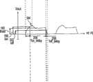
[0039]图5A示出了全桥电枪驱动器154和电喷枪100之间的功率信号的一个实施例。在一个实施例中,功率信号由全桥驱动器154基于来自控制电子设备152的控制信号172产生。在这个实例中,在功率信号电压180保持为零的期间,例如在时间间隔PWMoff181期间,电喷枪100是关闭的。在功率信号保持为正电压,或者被调制成使得通过螺线管130的电流保持高得足以使枪动铁芯136保持打开的期间,例如在PWMon183期间,枪100是打开的。时间间隔PWMon183对时间间隔PWMoff181的关系表示用于控制枪的喷涂启动时间的低频脉冲宽度调制信号。下文结合功率信号论述了喷枪的打开和关闭的更加详细的描述。[0039] FIG. 5A shows one embodiment of the power signal between the full
[0040]图5B示出了通过电喷枪100中的螺线管130的电流184。在时间间隔Tpos182期间,控制电子设备152使功率信号180保持为正电压Vpos186。在时间间隔Tpos182期间,通过螺线管130的电流184从大大约为零斜坡上升到大于Ion188的值。Ion188表示足以开始移动电喷枪的动铁芯136的、通过螺线管130的电流。在时间间隔Tpos182的结尾,电压180保持为大约为零,直到通过螺线管130的电流184大约等于Ihold190为止。Ihold190表示足以吸引动铁芯136从而使得枪保持打开的、通过螺线管130的电流。动铁芯136被吸引,从而使得枪在Thold192时段期间保持打开。为了在整个时间Thold192期间维持Ihold190,以CHOPon194对CHOPoff196的比率对功率信号180进行调制。CHOPon194对CHOPoff196的比率表示用于维持Ihold190的高频调制信号。在这个实施例中,CHOPon194大约等于Vpos186,CHOPoff196大约等于零。但是任何适当的值可用于CHOPon194和CHOPoff196,从而使得通过螺线管130的电流大约等于Ihold190或更大。[0040] FIG. 5B shows the current 184 through the
[0041]为了确保迅速地关闭阀,来自全桥驱动器154的功率信号180在时间间隔PWMoff181期间保持为大约为零。通过将功率信号180驱动到负电压Vneg198一段短的时段Tneg200,通过螺线管130的电流184比在功率信号电压186保持为大约为零的情况下更快达到Ioff202。Ioff202表示在该电流下螺线管130释放动铁芯136从而使枪关闭的、通过螺线管130的电流。在Tneg200时间间隔的结尾,通过螺线管130的电流184大约为零。在这个实例中,在Tneg200时段的结尾,枪驱动器154使功率信号电压180保持为大约为零以PWMoff181时段的剩余时间。[0041] To ensure rapid valve closing, the
[0042]图5C示出了电喷枪100的动铁芯位置204。动铁芯的位置由通过螺线管130的电流184确定。在一个实施例中,当通过螺线管130的电流184小于Ion188时,动铁芯136关闭。在通过螺线管130的电流184达到Ion188之后,动铁芯136朝打开位置移动。为了使动铁芯136维持在打开位置上,通过螺线管的电流必须保持大于或等于Ihold190。Ton_delay206表示从PWMon183和正功率信号电压180的开始直到通过螺线管的电流足以在Ion188下吸引动铁芯136为止的时间。一些额外的时间之后,动铁芯处于完全地打开的位置210,同时通过螺线管130的电流184增大。类似地,Toff_delay208表示从PWMoff181的开始直到动铁芯136开始关闭为止的时间。当通过螺线管130的电流180大约等于零时,动铁芯136完全关闭。为了尽可能精确地喷涂,希望最大程度地减小Ton_delay206和Toff_delay208。[0042] FIG. 5C shows the moving
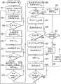
[0043]图6的流程图示出了驱动电喷枪100以实现改进的枪阀打开和关闭响应时间的一种方法。用于驱动喷枪100的方法可在控制电子设备152中实现。一个优选实施例在运行在微控制器上的软件中实现该方法。图6所示的方法使用已知的枪阀打开时间Tpos182和关闭时间Tneg200。另外,保持电流Ihold190是已知的。图6上的步骤212对应于PWMon183开始时的喷涂循环的开始。[0043] The flowchart of FIG. 6 illustrates one method of driving the
[0044]在步骤212,在时段Tpos182期间施加标称工作电压Vpos186,直到动铁芯136在位置210处处于完全打开状态为止。标称工作电压是足以使喷枪的动铁芯136保持打开且维持Ihold190(图5B)的电压。在步骤214移除该电压,且将其保持为大约为零。在步骤216期间,测量通过螺线管130的电流184。在决策步骤218,系统检测通过螺线管130的电流184是否等于Ihold190,这是电流184至少足以使动铁芯136保持打开的电流。只要电流184大于Ihold,系统就继续在步骤216监测螺线管电流。一旦电流184等于Ihold190,脉冲宽度调制功率信号180就在步骤220被供应到螺线管130。以CHOPon194对CHOPoff196的比率对功率信号180进行调制,其中该比率足以维持Ihold190。在决策步骤222,系统确定是否已经到达PWMon183的结尾。如果到达了PWMon183的结尾,系统就施加标称工作电压Vneg198以等于Tneg200的一段时间。在Tneg200之后,螺线管电流184大约等于零。步骤226使电流保持为零。在决策步骤228,系统确定是否已经到达PWMoff181的结尾。当到达了PWMoff181的结尾时,就开始下一个循环,且方法返回步骤212。[0044] At
[0045]图7的流程图示出了驱动电喷枪100以实现快速的枪打开和关闭时间的一种备选方法。图7所示的方法使用喷枪100的启动电流Ion188和保持电流Ihold190。步骤230对应于在PWMon183开始时的喷涂循环的开始。高于标称工作电压的电压Vpos186施加于螺线管130。在步骤232,监测通过螺线管130的电流184。在决策步骤234,系统确定电流184是否等于Ion188,这是开始吸引动铁芯136所必需的电流。如果电流184不等于Ion188,继续监测螺线管电流(步骤232),否则在步骤236维持Vpos186以安全时间间隔。安全时间间隔确保枪完全打开。在本发明的一些实施例中可排除此时间间隔。基于特定的枪、喷涂控制系统和所施加的液体或空气压力来确定安全时间间隔。在安全时间间隔之后,在步骤238移除Vpos186。接下来,监测螺线管130电流184(步骤240)。[0045] The flowchart of FIG. 7 shows an alternative method of driving the
[0046]在决策步骤242,系统确定电流184是否等于Ihold190,即使动铁芯136保持在打开状态所必须的电流。如果电流184大于Ihold190,则系统继续监测电流184(步骤240)。如果电流184等于Ihold190,则脉冲宽度调制功率信号180在步骤244供应到螺线管130。以CHOPon194对CHOPoff196的比率对功率信号180进行调制,其中该比率足以维持Ihold190。CHOPon194对CHOPoff196的比率产生高频调制功率信号180。在决策步骤246,系统确定是否已经到达正在循环的喷涂(即PWMon183)的结尾。如果还没有到达PWMon183的结尾,则系统继续施加斩波功率信号180。当到达了PWMon183的结尾时,则在步骤248施加高于标称工作电压的电压Vneg198。[0046] At
[0047]系统监测螺线管电流184(步骤250)。在决策步骤252,系统确定螺线管电流184是否等于零。如果电流184不等于零,则系统继续监测电流184(步骤250)。当电流184等于零时,则移除Vneg198(步骤254),且使电压180保持为零(步骤256)。在决策步骤258,系统确定是否已经到达PWMoff181时段的结尾。如果还没有到达PWMoff181的结尾,则系统继续使电压180保持为零。如果已经到达了PWMoff的结尾,则系统通过返回步骤230来开始下一个喷涂循环。[0047] The system monitors the solenoid current 184 (step 250). At
[0048]图7所示的方法在步骤230处施加高于标称工作电压的电压Vpos186,且在步骤248处施加高于标称电压的电压Vneg198。高于标称的电压Vpos186允许通过螺线管130的电流184以更高的比率增大。因此,动铁芯136以更快的比率移动,使得枪更加快速地打开。相反,高于标称的电压Vneg198允许通过螺线管130的电流184以更高的比率减小。因此,动铁芯136以更快的比率移动,使得枪更加快速地关闭。通过在步骤232和250处监测通过螺线管130的电流184,系统可确定移除高于标称电压的电压的适当时间。在图7所示的方法中,螺线管电流184与螺线管130串联而被直接测量。虽然图7的方法优选地采用高于标称电压的电压,但是也可使用标称的电压Vpos186和Vneg198。[0048] The method shown in FIG. 7 applies a
[0049]图8的流程图示出了用于驱动电喷枪100以实现更快速的打开和关闭时间的本发明的实施例。图8所示的方法使用喷枪100的启动电流Ion188和保持电流Ihold190。另外,该方法允许通过桥驱动器154的低侧170a(图4)来估计螺线管电流184。图5D中描绘了在桥驱动器的低侧170a处测得的电流185。或者,在另一个实施例中,通过监测桥驱动器的高侧上的源电流170b来测量螺线管电流,源电流170b基本等于螺线管电流。当参考大地时,则表示如图5D中所描绘的电流185。所示的方法显示了在给定时间间隔之后,例如喷涂系统的每100次循环之后,执行可选校准。可按需改变校准过程的频率。另外,如果不需要校准,例如如果喷涂系统维持一致的参数,则可从方法中排除校准过程。以下对校准过程进行了更详细的描述。[0049] The flowchart of FIG. 8 illustrates an embodiment of the present invention for driving an
[0050]图8所示的实例确定喷涂系统是否已经循环了100次。在这个实例中,计数器“PWM循环”用于跟踪循环的次数。在初始化所示的方法时,计数器设定为零(步骤260)。在将计数器设定为零之后,在步骤262,高于标称工作电压的电压Vpos186施加于螺线管130。在步骤264,监测通过螺线管130的电流184。在桥驱动器154吸收侧170a(图4)处监测电流184。吸收电流测量值164等于螺线管电流184。在决策步骤266,系统确定电流184是否等于Ion188,即开始吸引动铁芯136所必需的电流。如果电流184不等于Ion188,则系统继续监测电流184(步骤264)。当电流184等于Ion188时,在步骤268处,系统可选地维持Vpos186以安全时间间隔。安全时间间隔确保枪完全打开。[0050] The example shown in FIG. 8 determines whether the spray system has cycled 100 times. In this example, the counter "PWM Cycles" is used to keep track of the number of cycles. Upon initializing the method shown, a counter is set to zero (step 260). After setting the counter to zero, at step 262 a
[0051]基于特定的枪、喷涂控制系统和所施加的液体或空气压力来确定安全时间间隔。在安全时间间隔之后,在步骤270移除Vpos186。接下来,在步骤272处,通过吸收电流测量装置164监测螺线管130电流184。在决策步骤274,系统确定电流184是否等于Ihold190,这是使动铁芯136保持在打开状态所必需的电流。如果电流184大于Ihold190,则系统继续监测电流184(步骤240)。如果电流184等于Ihold190,则脉冲宽度调制功率信号180在步骤276被供应到螺线管130。以CHOPon194对CHOPoff196的比率对功率信号180进行调制,其中该比率足以维持Ihold190。在决策步骤278,系统确定是否已经到达正在循环的喷涂(PWMon183)的结尾。如果还没有到达PWMon183的结尾,系统继续施加斩波功率信号180。当到达了PWMon183的结尾时,在步骤280处施加高于标称工作电压的电压Vneg198。[0051] The safety time interval is determined based on the particular gun, spray control system and applied fluid or air pressure. After a safe time interval,
[0052]当施加Vneg198时,系统在步骤282检查计数器“PWM循环”,以确定计数器是否等于零。如果计数器等于零,则系统处于校准循环中。在步骤284,系统开始计算施加Vneg198的时间(Tneg)。在决策步骤288,系统监测全桥驱动器的低侧170a处的电流185。电流185由于反电磁力(EMF)而在PWMon183变成零时转变极性。当螺线管放电时,电流185返回零。当电流185从负值过渡到正值时,系统在步骤290停止计算时间,且在步骤292增加计数器。移除Vneg198(步骤294),且使电压180保持为零(步骤296)。在决策步骤298,系统确定是否已经到达PWMoff181时段的结尾。如果还没有到达PWMoff181时段的结尾,则系统继续使电压180保持为零(步骤296)。如果已经到达PWMoff的结尾,则系统通过返回至步骤262来开始下一个喷涂循环。[0052] WhenVneg 198 is applied, the system checks the counter "PWM Cycles" at
[0053]返回至步骤282,如果计数器不等于零,则系统不处于校准循环中。在步骤300,施加Vneg198以预定的时间Tneg_red,其中Tneg_red小于Tneg。因此,Tneg_red在螺线管电流184放电之后补偿低侧桥174a电流185中的尖峰。在这个实例中,在校准过程期间计算Tneg_red,且使Tneg_red等于Tneg。然而,在不需要校准循环的情况下,也可预先确定维持Vneg198的时间长度。另外,可仅在系统启动时或者在手动地或自动地选择的任何时间间隔处运行校准循环。在施加Vneg198之后,在决策步骤302,系统确定计数器“PWM循环”是否小于预定的校准时间间隔。在这个实例中,校准时间间隔设定为100。如果计数器小于校准时间间隔,则计数器增加(步骤304)。如果计数器不小于校准时间间隔,则将计数器设定为零。[0053] Returning to step 282, if the counter is not equal to zero, the system is not in a calibration loop. At
[0054]在这个实例中,系统下一次到达决策步骤282处时,将基于等于零的计数器执行校准。在步骤304或步骤306中设定了计数器之后,系统在步骤296保持零电压,如以上所述的校准循环。在决策步骤298,系统确定是否已经到达PWMoff181时段的结尾。如果还没有到达PWMoff181的结尾,则系统继续使电压180保持为零(步骤296)。如果已经到达PWMoff的结尾,则系统通过返回至步骤262来开始下一个喷涂循环。[0054] In this example, the next time the system reaches
[0055]图9的流程图示出了使用枪启动/停止检测和根据本发明的一个实施例的枪的保持电流来控制电喷枪的一种方法。该方法在步骤308开始,将高于标称工作电压的电压Vpos186施加到螺线管130直到枪打开为止。可使用许多方法和装置(包括压敏变送器)来检测枪是否为打开的。下文更加详细地论述了使用压敏变送器来检测枪是否为打开的方法和电路。[0055] FIG. 9 is a flowchart showing one method of controlling an electrospray gun using gun start/stop detection and gun hold current according to one embodiment of the invention. The method begins at step 308 by applying a
[0056]在枪打开之后,在步骤310移除Vpos186。在步骤312,监测通过螺线管的电流184。在决策步骤314,系统确定电流184是否等于枪的保持电流Ihold190。如果电流184不等于Ihold190,则步骤312继续监测电流。如果Ihold190等于电流184,则施加斩波Vpos186,从而使得以CHOPon194对CHOPoff196的比率对信号进行调制,其中该比率足以维持Ihold190。在决策步骤318,系统确定是否已经到达正在循环的喷涂PWMon183的结尾。如果还没有到达PWMon183的结尾,系统继续施加斩波功率信号180。当到达了PWMon183的结尾时,在步骤320施加高于标称工作电压的电压Vneg198,直到枪关闭为止。在决策步骤322,系统确定是否已经到达PWMoff181时段的结尾。如果还没有到达PWMoff181的结尾,系统继续使电压180保持为零(步骤322)。如果已经到达PWMoff的结尾,系统通过返回至步骤262来开始下一个喷涂循环。[0056] After the gun is turned on, the
[0057]虽然前述实例实现了本发明内的用于控制电喷枪的适当的方法,但是将理解,仅出于说明性目的而提供这些实例。因此,还构思了本发明内的用于控制电喷枪的其它方法。另外,还构思了以上示例性方法的各方面将按特定的应用需要进行组合。[0057] While the foregoing examples implement suitable methods for controlling an electrospray gun within the present invention, it will be understood that these examples are provided for illustrative purposes only. Accordingly, other methods for controlling an electrospray gun within the present invention are also contemplated. In addition, it is also contemplated that aspects of the above exemplary methods will be combined as needed for a particular application.
[0058]为了有效地控制电喷枪,可能需要多个参数。用于控制喷枪的参数的实例为Ion188、Ioff202和Ihold190。Ion188表示足以吸引电喷枪的动铁芯136从而使得枪开始打开的、通过螺线管130的电流。Ioff202表示在枪100中的动铁芯136释放且枪开始关闭时的、通过螺线管130的电流。Ihold190表示足以保持动铁芯136从而使得枪保持在打开位置上的、通过螺线管130的电流。然而,控制喷枪的特定方法可使用所有的参数,不使用任何参数,或者使用参数的某个组合。[0058] To effectively control an electrospray gun, a number of parameters may be required. Examples of parameters for controlling the spray gun are Ion 188 , Ioff 202 and Ihold 190 . Ion 188 represents the current through the
[0059]图10提供了用于确定Ion188、Ioff202和Ihold190的诊断程序。可按需要运行诊断程序来确定用于特定喷枪100的参数。如果喷枪厂商为特定系统提供了值,则可能不需要诊断程序。程序在步骤326开始,将标称工作电压Vpos186施加于螺线管130直到枪打开为止。一旦枪打开,就在步骤328测量通过螺线管130的电流184,以确定Ion188。不从螺线管130中移除电压。在步骤330,监测螺线管电流184。在决策步骤332,系统确定电流184是否在增大。如果电流继续增大,则步骤330继续监测螺线管电流184。当电流停止增大时,在步骤334测量标称螺线管电流。[0059] FIG. 10 provides a diagnostic procedure for determiningIon 188,Ioff 202, andIhold 190. Diagnostics may be run to determine parameters for a
[0060]在步骤336,施加斩波Vpos186,从而使得以CHOPon194对CHOPoff196的比率对信号进行调制。斩波信号的占空比逐渐减小,直到枪关闭为止。当枪关闭时,测量通过螺线管130的电流184,以确定Ioff202。Ioff202表示在枪100中的动铁芯136释放使枪关闭时的、通过螺线管130的电流。在确定Ioff202之后,可根据关系Ihold=Ioff+(Ion-Ioff)/2来计算Ihold190。但是,可通过对Ioff202添加区间量且确定枪是否保持打开来获得另外的Ihold190值。例如,对Ioff202的值添加10%可足以保持枪打开。如果对Ioff202的值添加10%不能使枪保持打开,则系统可以重复地增大添加到Ioff202的区间量,例如20%,并且确定枪是否保持打开。[0060] At
[0061]在确定Ihold190之后,在步骤342计算工作值。例如,特定系统可能需要百分之五的安全区间量。在这种情况下,用于Ioff的工作值将为计算出的Ioff-5%。用于Ion的工作值将为计算出的Ion+5%。取决于应用和喷涂系统,安全区间量可从0(即无区间量)调节到任何适当的区间量。如图10所示,在步骤342计算工作值,但是可在示例性程序期间的任何时间计算工作值。例如,还可在步骤338中在测量Ioff202的时候计算Ioff202的工作值。[0061] After determiningIhold 190, at
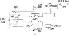
[0062]为了检测根据本发明的实施例的电喷枪的启动/停止位置,提供了例如图11的示意图中所示的电路。通过提供启动/停止检测电路,图10示出的方法可有效地计算Ion、Ioff和Ihold。但是,启动/停止检测电路和诊断程序在本发明的所有实施例中不一定都是必要的。例如,枪厂商可为终端用户提供这些值。可通过其它手段来确定这些值。图11示出的电路包含为压力变送器桥366提供稳定的电源电压的电压电源V_REF364和电阻器368。压力变送器桥置于枪100喷嘴组件148的前面,在桥366和喷嘴148之间有小的空气间隙。可以饱和的方式使用高增益测量放大器372。电池370为放大器372提供启动电压。第二电池374为放大器372提供停止电压。应当注意,虽然此实例使用了电池370、374,但是可使用任何适当的功率源。可变的偏移电压376使放大器372偏置。偏移电压设定成使得放大器372的输出在大气压下电平固定于电池374。由启动位置上的枪100引起的空气压力使放大器372基本在枪100打开的时候电平固定于正电池370。场效应晶体管(FET)380连接到放大器372上,且提供来自电路的数字量输出378。在这个实例中,FET 380在大气压下是打开的,这是当枪100于关闭位置时。当枪100打开时,FET转换成接地。因此,通过监测数字量输出378,可确定枪100是否在打开(启动)或关闭(停止)位置上。[0062] In order to detect the start/stop position of the electrospray gun according to an embodiment of the present invention, a circuit such as that shown in the schematic diagram of FIG. 11 is provided. By providing a start/stop detection circuit, the method shown in FIG. 10 can efficiently calculate Ion , Ioff and Ihold . However, start/stop detection circuitry and diagnostic routines are not necessarily necessary in all embodiments of the invention. For example, gun manufacturers may provide these values to end users. These values may be determined by other means. The circuit shown in FIG. 11 includes a
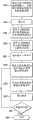
[0063]图12的流程图示出了使用用于检测图11中所示的电喷枪的启动/停止位置的实例电路来计算枪参数的一个示例性方法。在步骤344,液体供给端口112连接到诸如空气压缩机的提供空气压力的装置上。图11中所示的电路连接到枪100上,且数字量输出378为图10中所示的实例枪诊断程序提供数据。在步骤346,不将空气压力施加于系统。在步骤348,偏移电压376调节成使得FET开关380的输出378在大气压下为启动。在步骤350,基准电压376调节成使得输出378在大气压下正好转为停止。[0063] The flowchart of FIG. 12 illustrates one exemplary method of calculating gun parameters using the example circuit for detecting the start/stop position of the electrospray gun shown in FIG. 11. At step 344, the
[0064]在步骤352将最大工作压力施加于枪,且压力变送器在步骤354置于枪喷嘴148的前面。施加最大工作压力,因为螺线管的磁力必须克服来自弹簧146和摩擦的机械力以及来自喷涂的液体的力两者。在步骤356执行诊断程序。图10提供了与图12中所示的方法一起使用的诊断程序的一个实例。在步骤358,根据步骤356的诊断程序进行测量。在步骤360,确定是否要测量另一个枪。如果要测量另一个枪,则方法返回至步骤354并使用新枪。如果不要测量另外的枪,则方法在步骤362结束。[0064] A maximum operating pressure is applied to the gun at
[0065]图12中提供的方法提供了使用启动/停止检测电路来产生枪参数的一种方式。启动/停止检测电路还可集成到电喷枪中,从而使得枪的启动/停止状态直接用于枪的控制程序中。例如,图9提供直接利用枪的启动/停止状态来控制喷枪的一个示例性方法。[0065] The method provided in FIG. 12 provides one way to use the start/stop detection circuit to generate gun parameters. The start/stop detection circuit can also be integrated into the electric spray gun, so that the start/stop status of the gun can be directly used in the gun control program. For example, FIG. 9 provides one exemplary method of controlling a spray gun directly using the start/stop state of the gun.
[0066]本文所述的电喷枪和喷枪系统提供了许多益处和改进。本发明的一些实施例提供容易且有效地安装的喷枪系统。本发明的另外的实施例提供功率高效的喷枪系统。通过使用本发明可实现更迅速的枪打开和枪关闭时间。例如,图8的流程图示出了驱动电喷枪以实现快速的打开和快速的关闭时间的示例性方法。可组合示例性系统和方法的方面,以对喷枪系统实现功率高效性、系统配置的容易性以及快速打开和关闭时间。[0066] The electrospray guns and spray gun systems described herein provide a number of benefits and improvements. Some embodiments of the present invention provide an easily and efficiently installed spray gun system. Additional embodiments of the present invention provide power efficient spray gun systems. Faster gun open and gun close times can be achieved through use of the present invention. For example, the flowchart of FIG. 8 illustrates an exemplary method of driving an electrospray gun to achieve fast opening and fast closing times. Aspects of the exemplary systems and methods may be combined to achieve power efficiency, ease of system configuration, and fast turn-on and turn-off times for spray gun systems.
[0067]本文所引用的所有参考文献,包括出版物、专利申请和专利,通过引用而结合,结合程度与在各个参考文献单独地和特别地表明通过引用而结合且阐明其整体的结合程度相同。[0067] All references cited herein, including publications, patent applications, and patents, are incorporated by reference to the same extent as if each reference were individually and specifically indicated to be incorporated by reference and set forth in its entirety .
[0068]在描述本发明的上下文中(特别是在权利要求书的上下文中)使用的用语“一”和“一个”和“该”以及类似的所指对象应理解为覆盖单数和复数两者,除非本文另有说明,或者由上下文清楚地提出相反的说法。用语“包括”、“具有”、“包含”应理解为无限制用语(即,意思是“包括,但不限于”),除非另有说明。值的范围的叙述在本文中仅意图用作单独地引用落在该范围内的各个单独的值的简化方法,除非在本文中另有说明,各个单独的值如本文个别地叙述那样结合在说明书中。可以以任何适当的顺序执行本文所述的所有方法,除非在本文中另有说明,或者由上下文清楚地提出相反的说法。本文提供的任何和所有实例、或示例性语言(例如“诸如”)仅意图更好地阐明本发明,且不对本发明的范围施加限制,除非另有说明。说明书中的语言不应理解为表明未要求保护的任何元件对实践本发明是必要的。[0068] The terms "a" and "an" and "the" and similar referents used in the context of describing the present invention (especially in the context of the claims) should be understood to cover both the singular and the plural , unless otherwise indicated herein or otherwise clearly stated to the contrary by the context. The terms "including", "having", and "comprising" are to be read without limitation (ie, meaning "including, but not limited to") unless otherwise stated. Recitation of ranges of values herein are merely intended to serve as a shorthand method of referring individually to each separate value falling within the range, unless otherwise indicated herein, and each separate value is incorporated into the specification as if it were individually recited herein. middle. All methods described herein can be performed in any suitable order unless otherwise indicated herein or otherwise clearly contradicted by context. Any and all examples, or exemplary language (eg, "such as") provided herein, are intended merely to better illuminate the invention and do not pose a limitation on the scope of the invention unless otherwise claimed. No language in the specification should be construed as indicating any non-claimed element as essential to the practice of the invention.
[0069]本文对本发明的优选实施例进行了描述,包括用于实现本发明的发明人已知的最佳模式。阅读前述描述后,那些优选实施例的变型对本领域技术人员可变得显而易见。发明人可预见到技术人员适当地采用这种变型,且发明人意图以其它的方式而不是如本文特别描述的那样实践本发明。因此,本发明包括可适用的法律所允许的权利要求书中叙述的本主题的所有修改和等效物。此外,本发明包括任何可能的变形的方式的上述元素的任何组合,除非在本文中另有说明,或者由上下文清楚地提出相反的说法。[0069] Preferred embodiments of this invention are described herein, including the best mode known to the inventors for carrying out the invention. Variations of those preferred embodiments may become apparent to those of ordinary skill in the art upon reading the foregoing description. The inventors foresee skilled artisans employing such variations as appropriate, and the inventors intend for the invention to be practiced otherwise than as specifically described herein. Accordingly, this invention includes all modifications and equivalents of the subject matter recited in the claims as permitted by applicable law. Furthermore, any combination of the above-described elements in any possible variant is encompassed by the invention unless otherwise indicated herein or otherwise clearly indicated to the contrary by the context.
Claims (32)
Translated fromChineseApplications Claiming Priority (3)
| Application Number | Priority Date | Filing Date | Title |
|---|---|---|---|
| US11/682,651 | 2007-03-06 | ||
| US11/682,651US20080217437A1 (en) | 2007-03-06 | 2007-03-06 | Optimized Method to Drive Electric Spray Guns |
| PCT/US2008/056080WO2008109765A2 (en) | 2007-03-06 | 2008-03-06 | Optimized method to drive electric spray guns |
Publications (1)
| Publication Number | Publication Date |
|---|---|
| CN101674890Atrue CN101674890A (en) | 2010-03-17 |
Family
ID=39739116
Family Applications (1)
| Application Number | Title | Priority Date | Filing Date |
|---|---|---|---|
| CN200880014616.7APendingCN101674890A (en) | 2007-03-06 | 2008-03-06 | Optimized method of driving an electric spray gun |
Country Status (9)
| Country | Link |
|---|---|
| US (1) | US20080217437A1 (en) |
| EP (1) | EP2131963A4 (en) |
| JP (1) | JP2010520057A (en) |
| CN (1) | CN101674890A (en) |
| AU (1) | AU2008222783A1 (en) |
| BR (1) | BRPI0808645A2 (en) |
| CA (1) | CA2679946A1 (en) |
| RU (1) | RU2009136735A (en) |
| WO (1) | WO2008109765A2 (en) |
Cited By (3)
| Publication number | Priority date | Publication date | Assignee | Title |
|---|---|---|---|---|
| CN105163863A (en)* | 2013-04-09 | 2015-12-16 | 萨姆斯技术公司 | Apparatus for electrostatically spraying a coating product and method for controlling generator for supplying power to a high voltage unit in such an apparatus |
| CN117073743A (en)* | 2022-10-18 | 2023-11-17 | 深圳市质远科技有限公司 | Plug access falling detection circuit and device of low-temperature plasma rotary spray gun |
| US12237108B2 (en) | 2022-06-29 | 2025-02-25 | Smart Wires Inc. | Power dumping driver for magnetic actuator |
Families Citing this family (13)
| Publication number | Priority date | Publication date | Assignee | Title |
|---|---|---|---|---|
| WO2011002736A1 (en)* | 2009-06-29 | 2011-01-06 | Spraying Systems Co. | Low fluid volume antimicrobial mold reduction system and method |
| CA2738522C (en) | 2010-05-03 | 2018-01-02 | Chapin Manufacturing, Inc. | Spray gun |
| US8794547B2 (en)* | 2012-05-15 | 2014-08-05 | Stolle Machinery Company, Llc | Smart solenoid compound gun driver and automatic calibration method |
| EP3081314A1 (en)* | 2015-04-16 | 2016-10-19 | Eftec Europe Holding AG | Device for applying fluids |
| KR101866472B1 (en)* | 2016-08-22 | 2018-06-11 | (주)메가이엔씨 | A Nozzle Assembly Having a Structure of Pulse Width Modulation for Controlling a Spray |
| KR101874624B1 (en)* | 2016-09-22 | 2018-07-04 | 박정현 | Automatic sprayer using pulse width modulation |
| US10300609B2 (en)* | 2016-12-15 | 2019-05-28 | Boston Dynamics, Inc. | Motor and controller integration for a legged robot |
| WO2018132790A1 (en)* | 2017-01-15 | 2018-07-19 | Graco Minnesota Inc. | Paint sprayer with dynamic pulse width modulation driven motor |
| DE102017122492A1 (en)* | 2017-09-27 | 2019-03-28 | Dürr Systems Ag | Applicator with an integrated control circuit |
| CN209164045U (en)* | 2018-11-19 | 2019-07-26 | 浙江锐韦机电科技有限公司 | Integrated pump valve mechanism |
| EP3999243A1 (en)* | 2019-07-15 | 2022-05-25 | Spraying Systems Co. | Low drift, high efficiency spraying system |
| US10787372B1 (en)* | 2019-12-20 | 2020-09-29 | E3 Solutions, Llc | Solar-powered buoyant evaporation system |
| KR20240158974A (en) | 2022-03-09 | 2024-11-05 | 그라코 미네소타 인크. | Fluid sprayer |
Family Cites Families (27)
| Publication number | Priority date | Publication date | Assignee | Title |
|---|---|---|---|---|
| US3344992A (en)* | 1964-01-27 | 1967-10-03 | Edward O Norris | Spray gun |
| US3583632A (en)* | 1969-05-23 | 1971-06-08 | Binks Mfg Co | Electrostatic spray coating apparatus |
| US3940061A (en)* | 1974-09-16 | 1976-02-24 | Champion Spark Plug Company | Electrostatic spray gun for powder coating material |
| DE3003384C2 (en)* | 1980-01-31 | 1984-09-13 | Hugo Brennenstuhl GmbH & Co KG, 7400 Tübingen | Method and circuit for operating a spray gun with oscillating armature drive |
| US4454456A (en)* | 1981-05-07 | 1984-06-12 | Hugo Brennenstuhl Gmbh & Co. Kg | Method and circuit for operating a spray gun having a vibrating armature drive |
| US4844342A (en)* | 1987-09-28 | 1989-07-04 | The Devilbiss Company | Spray gun control circuit |
| US5409163A (en)* | 1990-01-25 | 1995-04-25 | Ultrasonic Systems, Inc. | Ultrasonic spray coating system with enhanced spray control |
| GB9101812D0 (en)* | 1991-01-28 | 1991-03-13 | Morgan Crucible Co | Dispensing of fluids |
| US5520735A (en)* | 1992-06-30 | 1996-05-28 | Nordson Corporation | Nozzle assembly and system for applying powder to a workpiece |
| US5381297A (en)* | 1993-06-18 | 1995-01-10 | Siemens Automotive L.P. | System and method for operating high speed solenoid actuated devices |
| US5400975A (en)* | 1993-11-04 | 1995-03-28 | S. C. Johnson & Son, Inc. | Actuators for electrostatically charged aerosol spray systems |
| US5725151A (en)* | 1996-10-03 | 1998-03-10 | Ford Global Technologies, Inc. | Electrospray fuel injection |
| GB2327895B (en)* | 1997-08-08 | 2001-08-08 | Electrosols Ltd | A dispensing device |
| US5972417A (en)* | 1997-11-14 | 1999-10-26 | Nordson Corporation | Spray gun power supply monitor |
| WO1999036182A1 (en)* | 1998-01-13 | 1999-07-22 | Abb K.K. | Rotary atomizing head type coating device |
| US6089413A (en)* | 1998-09-15 | 2000-07-18 | Nordson Corporation | Liquid dispensing and recirculating module |
| US6749128B1 (en)* | 1999-06-04 | 2004-06-15 | C-Dax Systems Limited | Spray control device |
| US6758423B1 (en)* | 1999-09-17 | 2004-07-06 | Nordson Corporation | Spray gun with data device and method of control |
| JP4786014B2 (en)* | 2000-06-29 | 2011-10-05 | アネスト岩田株式会社 | Electrostatic coating equipment |
| US7740225B1 (en)* | 2000-10-31 | 2010-06-22 | Nordson Corporation | Self adjusting solenoid driver and method |
| JP2005516771A (en)* | 2002-02-12 | 2005-06-09 | ノードソン コーポレーション | Control unit for internal power supply of electrostatic spray gun |
| US6827299B2 (en)* | 2003-01-24 | 2004-12-07 | Spraying Systems Co. | Gang mountable spray gun |
| US6817553B2 (en)* | 2003-02-04 | 2004-11-16 | Efc Systems, Inc. | Powder paint spray coating apparatus having selectable, modular spray applicators |
| DE602004020352D1 (en)* | 2003-07-24 | 2009-05-14 | Ransburg Ind Finishing Kk | ELECTROSTATIC PAINTING DEVICE |
| ITTO20030778A1 (en)* | 2003-10-03 | 2005-04-04 | Fiat Ricerche | CONTROL CIRCUIT FOR THE PILOT OF A |
| US20050279780A1 (en)* | 2004-04-30 | 2005-12-22 | Howard Evans | Switch mode gun driver and method |
| CN100522384C (en)* | 2004-08-04 | 2009-08-05 | 阿耐斯特岩田株式会社 | Spray gun with gas pressure detector |
- 2007
- 2007-03-06USUS11/682,651patent/US20080217437A1/ennot_activeAbandoned
- 2008
- 2008-03-06CACA002679946Apatent/CA2679946A1/ennot_activeAbandoned
- 2008-03-06RURU2009136735/05Apatent/RU2009136735A/enunknown
- 2008-03-06WOPCT/US2008/056080patent/WO2008109765A2/enactiveApplication Filing
- 2008-03-06AUAU2008222783Apatent/AU2008222783A1/ennot_activeAbandoned
- 2008-03-06EPEP08731568.5Apatent/EP2131963A4/ennot_activeWithdrawn
- 2008-03-06CNCN200880014616.7Apatent/CN101674890A/enactivePending
- 2008-03-06BRBRPI0808645-1Apatent/BRPI0808645A2/ennot_activeIP Right Cessation
- 2008-03-06JPJP2009552894Apatent/JP2010520057A/ennot_activeWithdrawn
Cited By (4)
| Publication number | Priority date | Publication date | Assignee | Title |
|---|---|---|---|---|
| CN105163863A (en)* | 2013-04-09 | 2015-12-16 | 萨姆斯技术公司 | Apparatus for electrostatically spraying a coating product and method for controlling generator for supplying power to a high voltage unit in such an apparatus |
| CN105163863B (en)* | 2013-04-09 | 2017-06-06 | 萨姆斯技术公司 | The method of the generator that the device for electrostatic spraying applicator and the high voltage unit for being controlled in the device are powered |
| US12237108B2 (en) | 2022-06-29 | 2025-02-25 | Smart Wires Inc. | Power dumping driver for magnetic actuator |
| CN117073743A (en)* | 2022-10-18 | 2023-11-17 | 深圳市质远科技有限公司 | Plug access falling detection circuit and device of low-temperature plasma rotary spray gun |
Also Published As
| Publication number | Publication date |
|---|---|
| EP2131963A2 (en) | 2009-12-16 |
| EP2131963A4 (en) | 2013-12-18 |
| US20080217437A1 (en) | 2008-09-11 |
| CA2679946A1 (en) | 2008-09-12 |
| AU2008222783A1 (en) | 2008-09-12 |
| JP2010520057A (en) | 2010-06-10 |
| RU2009136735A (en) | 2011-04-20 |
| BRPI0808645A2 (en) | 2014-08-12 |
| WO2008109765A3 (en) | 2008-12-04 |
| WO2008109765A2 (en) | 2008-09-12 |
Similar Documents
| Publication | Publication Date | Title |
|---|---|---|
| CN101674890A (en) | Optimized method of driving an electric spray gun | |
| US6895997B2 (en) | System for determining positions of a control element of an electrically driven actuator | |
| US6520382B2 (en) | Electrically operated viscous fluid dispensing apparatus | |
| US8465263B2 (en) | Dynamic control of an electric drive | |
| US6017017A (en) | Process and apparatus for the recognition of the state of a solenoid valve | |
| CN110998761A (en) | Diagnostic device and method for solenoid valve | |
| US11470997B2 (en) | Control assembly of a solenoid valve, solenoid valve assembly and associated methods | |
| US7740225B1 (en) | Self adjusting solenoid driver and method | |
| KR20110100124A (en) | Solenoid valve drive circuit, solenoid valve, and driving method of solenoid valve | |
| CN116696875A (en) | Method and fluid system for determining armature position of electromagnet | |
| JP4289883B2 (en) | Device for controlling the brake valve | |
| JP4443280B2 (en) | Solenoid plunger position detection device, solenoid valve, and direction switching valve | |
| JP2005317612A (en) | Solenoid plunger position detecting device and solenoid plunger position detecting method | |
| US6262620B1 (en) | Driver circuitry for latching type valve and the like | |
| US10804817B2 (en) | PWM control for electromagnetic valves | |
| US12313182B2 (en) | Solenoid valve system and method of operating a solenoid valve system | |
| JP3777265B2 (en) | solenoid valve | |
| EP3924992B1 (en) | Power supply and control circuit of a solenoid and piloting or switching device provided with said circuit | |
| JP2004021826A (en) | Method for driving solenoid valve | |
| JP7663026B2 (en) | Actuator drive device, solenoid valve device, electromagnetic contactor, and electromagnetic brake device | |
| JP7617841B2 (en) | Low power solenoid with dropout detection and automatic reenergization | |
| KR20040068769A (en) | Apparatus for temperature gauge of the solenoid coil in a vehicle | |
| CN115243946A (en) | Method and device for controlling a fluid solenoid valve | |
| JPH07122424A (en) | Drive circuit of electromagnet device |
Legal Events
| Date | Code | Title | Description |
|---|---|---|---|
| C06 | Publication | ||
| PB01 | Publication | ||
| C10 | Entry into substantive examination | ||
| SE01 | Entry into force of request for substantive examination | ||
| C02 | Deemed withdrawal of patent application after publication (patent law 2001) | ||
| WD01 | Invention patent application deemed withdrawn after publication | Application publication date:20100317 |