CN101673616B - Electric connector system - Google Patents
Electric connector systemDownload PDFInfo
- Publication number
- CN101673616B CN101673616BCN2008103044434ACN200810304443ACN101673616BCN 101673616 BCN101673616 BCN 101673616BCN 2008103044434 ACN2008103044434 ACN 2008103044434ACN 200810304443 ACN200810304443 ACN 200810304443ACN 101673616 BCN101673616 BCN 101673616B
- Authority
- CN
- China
- Prior art keywords
- coil
- circuit board
- electric connector
- external circuit
- transformer
- Prior art date
- Legal status (The legal status is an assumption and is not a legal conclusion. Google has not performed a legal analysis and makes no representation as to the accuracy of the status listed.)
- Active
Links
Images


Landscapes
- Details Of Connecting Devices For Male And Female Coupling (AREA)
- Coils Or Transformers For Communication (AREA)
Abstract
Description
Translated fromChinese【技术领域】【Technical field】
本发明涉及一种设有变压器与共模抑制模组的电连接器系统,尤其涉及其变压器及共模抑制模组的连接结构。The invention relates to an electrical connector system provided with a transformer and a common-mode suppression module, in particular to the connection structure of the transformer and the common-mode suppression module.
【背景技术】【Background technique】
传统具有变压器与共模抑制模组的电连接器产品中,通常做法是将变压器与共模抑制线圈连体设置,然后装设在电连接器的内置电路板上,最后再转接至外部电路板上。所述之传统设计中,变压器与共模抑制线圈组成模组的线圈需手工绕制,而手工绕制的方式效率低,线圈品质较差,且不利于生产流程中的自动化,从而导致了连接器的成本较大。In traditional electrical connector products with transformers and common mode suppression modules, the usual practice is to connect the transformer and common mode suppression coils together, then install them on the built-in circuit board of the electrical connector, and finally transfer them to the external circuit board . In the above-mentioned traditional design, the coils of the transformer and the common mode suppression coil form a module need to be wound manually, and the manual winding method is inefficient, the quality of the coil is poor, and it is not conducive to the automation of the production process, which leads to connectors The cost is higher.
因此,有必要对现有的技术进行改进以克服上述缺陷。Therefore, it is necessary to improve the existing technology to overcome the above-mentioned defects.
【发明内容】【Content of invention】
本发明所要解决的技术问题是:提供一种具有变压器与共模抑制模组的电连接器系统,其变压器与共模抑制模组之连接便于自动化生产,提高了效率,减小了成本。The technical problem to be solved by the present invention is to provide an electrical connector system with a transformer and a common-mode suppression module. The connection between the transformer and the common-mode suppression module facilitates automatic production, improves efficiency and reduces cost.
为解决上述技术问题,本发明提供一种电连接器系统,用以形成网络通路,其包括外部电路板、安装于外部电路板上的电连接器及装置于外部电路板与电连接器的共模抑制模组与变压器,该网络通路具有互为输入端与输出端的第一侧与第二侧,变压器包括第一线圈与第二线圈,共模抑制模组包括第三线圈与第四线圈,第一线圈的两端连接于上述第一侧,第二线圈的两端分别电性连接于第三与第四线圈的一端,第三与第四线圈的另一端连接至网络通路的第二侧,所述变压器还包括双连环形的磁芯,所述双连环形的磁芯设有由一中间壁隔开的两个并列通孔,所述第一、第二线圈贯穿两通孔共同缠绕于所述中间壁上,所述共模抑制模组为积层滤波器,第三、第四线圈由印刷导电层形成,且所述共模抑制模组在其外表面设有与第三、第四线圈电性连接的若干导接片,第三、第四线圈的另一端通过所述导接片最终与第二线圈的两端电性连接。In order to solve the above-mentioned technical problems, the present invention provides an electrical connector system for forming a network path, which includes an external circuit board, an electrical connector mounted on the external circuit board, and a common connector installed on the external circuit board and the electrical connector. A mode suppression module and a transformer, the network path has a first side and a second side which are input ends and output ends of each other, the transformer includes a first coil and a second coil, the common mode suppression module includes a third coil and a fourth coil, Two ends of the first coil are connected to the first side, two ends of the second coil are respectively electrically connected to one end of the third and fourth coils, and the other ends of the third and fourth coils are connected to the second side of the network path , the transformer also includes a double-connected annular magnetic core, the double-connected annular magnetic core is provided with two parallel through holes separated by an intermediate wall, and the first and second coils are wound through the two through holes On the middle wall, the common mode suppression module is a multilayer filter, the third and fourth coils are formed by printed conductive layers, and the common mode suppression module is provided with the third and fourth coils on its outer surface. The fourth coil is electrically connected to several conductive strips, and the other ends of the third and fourth coils are finally electrically connected to the two ends of the second coil through the conductive strips.
相较于现有技术,本发明之电连接器系统将变压器与共模抑制线圈分开独立设置并采用自动化的方式绕制,不仅提高了变压器及共模抑制模组的生产效率,而且提高了线圈的品质,且易于实现电连接器系统中变压器及共模抑制模组的自动化焊接生产。Compared with the prior art, the electrical connector system of the present invention separates the transformer and the common-mode suppression coil and independently sets them up and winds them in an automated manner, which not only improves the production efficiency of the transformer and common-mode suppression module, but also improves the efficiency of the coil. Quality, and easy to realize the automatic welding production of transformers and common mode suppression modules in the electrical connector system.
【附图说明】【Description of drawings】
图1是本申请人先前设计之第一种电连接器系统的组装立体视图。FIG. 1 is an assembled perspective view of the first electrical connector system previously designed by the applicant.
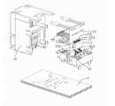
图2是图1所示电连接器系统的部分分解视图。FIG. 2 is a partially exploded view of the electrical connector system shown in FIG. 1 .
图3是图2所示内置电路板与变压器模组及共模抑制模组的配合示意图。FIG. 3 is a schematic diagram of cooperation of the built-in circuit board shown in FIG. 2 with the transformer module and the common mode suppression module.
图4是本申请人先前设计之第二种电连接器系统的组装立体视图。FIG. 4 is an assembled perspective view of a second electrical connector system previously designed by the applicant.
图5是图4所示电连接器系统的部分分解视图。FIG. 5 is a partially exploded view of the electrical connector system shown in FIG. 4 .
图6是图5所示外部电路板与变压器模组及共模抑制模组的配合示意图。FIG. 6 is a schematic diagram of cooperation between the external circuit board shown in FIG. 5 and the transformer module and the common mode suppression module.
图7是本申请人先前设计之第三种电连接器系统的组装立体视图。FIG. 7 is an assembled perspective view of a third electrical connector system previously designed by the applicant.
图8是图7所示电连接器系统的部分分解视图。FIG. 8 is a partially exploded view of the electrical connector system shown in FIG. 7 .
图9是图8所示内置电路板与变压器模组的配合示意图。FIG. 9 is a schematic diagram of cooperation between the built-in circuit board and the transformer module shown in FIG. 8 .
图10是本公司先前设计之第四种电连接器系统的组装立体视图。Fig. 10 is an assembled perspective view of the fourth electrical connector system previously designed by our company.
图11是图10所示电连接器系统的部分分解视图。FIG. 11 is a partially exploded view of the electrical connector system shown in FIG. 10 .
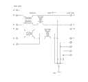
图12a是符合本申请人先前设计与本发明的一种10/100网络电连接器系统的电路图。Figure 12a is a circuit diagram of a 10/100 network electrical connector system consistent with the applicant's previous design and the present invention.
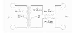
图12b是图12a中一个网络通路的电路示意图。Fig. 12b is a schematic circuit diagram of a network path in Fig. 12a.
图12c是图12a共模抑制模组省略接地用的第五线圈的电路示意图。12c is a schematic circuit diagram of the common mode suppression module in FIG. 12a omitting the fifth coil for grounding.
图12d是符合本申请人先前设计与本发明的一种10/1000网络电连接器系统的电路示意图。Fig. 12d is a schematic circuit diagram of a 10/1000 network electrical connector system according to the applicant's previous design and the present invention.
图13是符合本发明第一实施方式电连接器系统的部分分解视图。13 is a partially exploded view of an electrical connector system according to a first embodiment of the present invention.
图14是符合本发明第二实施方式电连接器系统的部分分解视图。14 is a partially exploded view of an electrical connector system according to a second embodiment of the present invention.
图15是符合本发明第三实施方式电连接器系统的部分分解视图。15 is a partially exploded view of an electrical connector system according to a third embodiment of the present invention.
图16是符合本发明第四实施方式电连接器系统的部分分解视图。16 is a partially exploded view of an electrical connector system according to a fourth embodiment of the present invention.
【具体实施方式】【Detailed ways】
图1至图3及图12a、图12b、图12c所示为本申请人的第一种先前设计,其揭示一种电连接器系统100,其包括一外部电路板1、安装于外部电路板1上的电连接器3、装置于电连接器3内的变压器5及共模抑制模组7。该电连接器系统100形成有两个用以传递差分信号的网络通路,各网络通路具有互为输入端与输出端的第一侧P与第二侧O。Figures 1 to 3 and Figures 12a, 12b, and 12c show the applicant's first previous design, which discloses an
所述电连接器3包括设有对接空间(未标号)的绝缘本体31、安装于绝缘本体31的内置电路板33、设置于内置电路板33一侧并延伸进入上述对接空间(未标号)的若干对接端子35、设置于内置电路板33另一侧并将内置电路板33连接至外部电路板1的若干转接端子37,所述对接端子35作为网络通路的第二侧O,转接端子37作为网络通路的第一侧P。所述内置电路板33设有若干导电路径331及连接于导电路径331的若干导电片333。The
所述变压器5包括第一线圈51与第二线圈53(结合参阅图12a所示),第一、第二线圈51、53均设有中心抽头55、57,所述变压器5的第一、第二线圈51、53的两端及中心抽头55、57均焊接于内置电路板33上的部分导电片333。共模抑制模组7包括绝缘的壳体71、收容于该壳体71内并缠绕于同一磁芯(未图示)的第三、第四、第五线圈73、75、79(结合参阅图12a所示)及设置于壳体71的若干导接脚77,所述第三、第四、第五线圈73、75、79的两端分别连接于所述各导接脚77,各导接脚77表面焊接于其余部分导电片333。第一线圈51的两端通过内置电路板33的部分导电路径331电性连接于转接端子37,第一线圈51的中心抽头55连接于内置电路板33的接地线路(未图示)。所述变压器5的第二线圈53的两端与中心抽头57通过部分导电路径331及导接脚77电性连接于共模抑制模组7的第三、第四、第五线圈73、75、79的一端。第三、第四线圈73、75的另一端通过导接脚77、内置电路板33的部分导电线路331电性连接于前述对接端子35,第五线圈79的另一端连接于内置电路板33的接地线路(未图示)。The
在此先前设计中,所述变压器5与共模抑制模组7的位置可以互换,即将变压器5的第一线圈51通过内置电路板33的导电路径331与对接端子35连接,而将共模抑制模组7的第三、第四线圈73、75的前述另一端通过内置电路板33的部分导电路径331与转接端子37连接。这样使对接端子35作为网络通路的第一侧P,转接端子37作为网络通路的第二侧O。In this previous design, the positions of the
图4至图6及图12a、图12b、图12c所示为本申请人的第二种先前设计,其揭示一种电连接器系统100,其包括一外部电路板1’、安装于外部电路板1’上的电连接器3’、装置于外部电路板1’上的变压器5’及共模抑制模组7’,该电连接器系统100形成有两个用以传递差分信号的网络通路,各网络通路具有互为输入端与输出端的第一侧P’与第二侧O’。Figures 4 to 6 and Figures 12a, 12b, and 12c show the applicant's second previous design, which discloses an
所述电连接器3’包括设有对接空间(未标号)的绝缘本体31’、安装于绝缘本体31’的内置电路板33’、设置于内置电路板33’一侧并延伸进入上述对接空间(未标号)的若干对接端子35’、设置于内置电路板33’另一侧并将内置电路板33’连接至外部电路板1’的若干转接端子37’,所述对接端子35’作为网络通路的第二侧O’。所述内置电路板33’设有若干导电路径331’。外部电路板1’设置有若干导电路径11’及连接于导电路径11’的导电片13’。The electrical connector 3' includes an insulating body 31' provided with a docking space (not numbered), a built-in circuit board 33' mounted on the insulating body 31', disposed on one side of the built-in circuit board 33' and extending into the above-mentioned docking space (unlabeled) a number of docking terminals 35', arranged on the other side of the built-in circuit board 33' and connecting the built-in circuit board 33' to a number of transfer terminals 37' of the external circuit board 1', the docking terminals 35' serve as The second side O' of the network path. The built-in circuit board 33' is provided with several conductive paths 331'. The external circuit board 1' is provided with a plurality of conductive paths 11' and conductive sheets 13' connected to the conductive paths 11'.
所述变压器5’包括第一线圈51’与第二线圈53’(结合参阅图12b所示),第一、第二线圈51’、53’均设有中心抽头55’、57’,所述变压器5’的第一、第二线圈51’、53’的两端及中心抽头55’、57’均焊接于外部电路板1’上的部分导电片13’。共模抑制模组7’包括绝缘的壳体71’、收容于该壳体71’内并缠绕于同一磁芯(未图示)的第三、第四、第五线圈73’、75’、79’(结合参阅图12b所示)及设置于壳体71’的若干导接脚77’,所述第三、第四、第五线圈73’、75’、79’的两端分别连接于所述各导接脚77’,各导接脚77’表面焊接于其余部分导电片13’。第三、第四线圈73’、75’的一端依次通过导接脚77’、外部电路板1’的部分导电路径11’、转接端子37’及内部电路板33’的导电路径331’电性连接于对接端子35’,另一端分别依次通过导接脚77’、外部电路板1’的部分导电路径11’电性连接于第二线圈53’的两端,第五线圈79’的一端连接于外部电路板1’的接地线路,另一端连接于变压器5’的第二线圈53’的中心抽头57’。第一线圈51’的中心抽头55’连接于外部电路板1’的接地线路(未图示),第一线圈51’的两端作为所述网络通路的第一侧P’。The transformer 5' includes a first coil 51' and a second coil 53' (shown in conjunction with FIG. Both ends of the first and second coils 51', 53' of the transformer 5' and the center taps 55', 57' are soldered to a part of the conductive sheet 13' on the external circuit board 1'. The common mode suppression module 7' includes an insulating housing 71', third, fourth and fifth coils 73', 75' housed in the housing 71' and wound on the same magnetic core (not shown), 79' (shown in conjunction with Fig. 12b) and a number of lead pins 77' arranged on the housing 71', the two ends of the third, fourth and fifth coils 73', 75', 79' are respectively connected to Each lead pin 77' is welded to the rest of the conductive sheet 13' on the surface of each lead pin 77'. One end of the third and fourth coils 73', 75' passes through the conductive pin 77', part of the conductive path 11' of the external circuit board 1', the transfer terminal 37' and the conductive path 331' of the internal circuit board 33'. The other end is electrically connected to the two ends of the second coil 53' and one end of the fifth coil 79' through the conductive pin 77' and the part of the conductive path 11' of the external circuit board 1' respectively. It is connected to the ground line of the external circuit board 1', and the other end is connected to the center tap 57' of the second coil 53' of the transformer 5'. The center tap 55' of the first coil 51' is connected to the ground line (not shown) of the external circuit board 1', and the two ends of the first coil 51' serve as the first side P' of the network path.
在此先前设计中,所述变压器5’与共模抑制模组7’的位置亦可以互换,即将变压器5’的第一线圈51’通过外部电路板1’的导电路径11’、转接端子37’及内置电路板33’的导电路径331’与对接端子35’连接,所述对接端子35’作为所述网络通路的第一侧P’,而共模抑制模组7’的第三、第四线圈73’、75’的前述一端作为网络通路的第二侧O’。In this previous design, the positions of the transformer 5' and the common mode suppression module 7' can also be interchanged, that is, the first coil 51' of the transformer 5' passes through the conductive path 11' of the external circuit board 1', the transfer terminal 37' and the conductive path 331' of the built-in circuit board 33' are connected to the docking terminal 35', the docking terminal 35' is used as the first side P' of the network path, and the third and third sides of the common mode suppression module 7' The aforementioned one end of the fourth coil 73', 75' serves as the second side O' of the network path.
图7至图9及图12a、图12b、图12c所示为本申请人的第三种先前设计,其揭示一种电连接器系统100,其包括外部电路板2、安装于外部电路板2上的电连接器4、及装置于外部电路板2与电连接器4的共模抑制模组8与变压器6,以形成若干网络通路,该等网络通路具有互为输入端与输出端的第一侧P与第二侧O。变压器6包括第一线圈61与第二线圈63,共模抑制模组8包括第三线圈83与第四线圈85,所述第三、第四线圈83、85共同缠绕于同一磁芯上,且所述共模抑制模组8还设有一壳体81与设置于壳体81的若干导接脚87,所述第三、第四线圈83、85收容于所述壳体81并连接于导接脚87。第一线圈61的两端与上述第一侧P相连接,第二线圈63的两端分别电性连接于第三与第四线圈83、85的一端,第三与第四线圈83、85的另一端连接至网络通路的第二侧O。所述电连接器4设有处于电连接器4内部的内置电路板43及连接内置电路板43与外部电路板2的若干转接端子47,所述变压器6设置于内置电路板43上,共模抑制模组8安装于外部电路板2,所述外部电路板2及内置电路板43分别设有若干导电路径21、431,所述第二线圈63的两端依次通过内置电路板43上的导电路径431、转接端子47、外部电路板2上的导电路径21以及导接脚87实现与第三、第四线圈83、85的电性连接。所述内置电路板43及外部电路板2还分别设有若干连接各导电路径431、21的导电片433、23,所述第一、第二线圈61、63分别焊接于内置电路板43的导电片433,所述导接脚87表面焊接于外部电路板2的导电片23。Figures 7 to 9 and Figures 12a, 12b, and 12c show a third prior design of the applicant, which discloses an
所述第一与第二线圈61、63均设有中心抽头65、67,第一线圈61的中心抽头65接地,共模抑制模组8还包括缠绕于所述同一磁芯上的第五线圈89,第二线圈63的中心抽头67电性连接于第五线圈89,并通过第五线圈89接地。The first and second coils 61, 63 are provided with center taps 65, 67, the
图10、图11及图12a、图12b、图12c所示为本申请人的第四种先前设计,其揭示一种电连接器系统100,其包括外部电路板2’、安装于外部电路板2’上的电连接器4’、及装置于外部电路板2’与电连接器4’的变压器6’与共模抑制模组8’,以形成多个网络通路,该等网络通路具有互为输入端与输出端的第一侧P’与第二侧O’,变压器6’包括第一线圈61’与第二线圈63’,共模抑制模组8’包括第三线圈83’与第四线圈85’,所述第三、第四线圈83’、85’共同缠绕于同一磁芯上,且所述共模抑制模组8’还设有一壳体81’与设置于壳体81’的若干导接脚87’,所述第三、第四线圈83’、85’收容于所述壳体81’并连接于所述导接脚87’。第一线圈61’的两端与上述第一侧P’相连接,第二线圈63’的两端分别电性连接于第三与第四线圈83’、85’的一端,第三与第四线圈83’、85’的另一端连接至网络通路的第二侧O’。所述电连接器4’设有处于电连接器4’内部的内置电路板43’及连接内置电路板43’与外部电路板2’的若干转接端子47’,所述共模抑制模组8’设置于内置电路板43’上,变压器6’安装于外部电路板2’,所述外部电路板2’及内置电路板43’分别设有若干导电路径21’、431’,第三、第四线圈83’、85’的两端依次通过导接脚87’、内置电路板43’上的导电路径431’、转接端子47’与外部电路板2’上的导电路径21’实现与第二线圈63’的两端电性连接。所述内置电路板43’及外部电路板2’还分别设有若干连接各导电路径431’、21’的导电片433’、23’,所述第一、第二线圈61’、63’焊接于外部电路板2’的导电片23’,所述导接脚87’表面焊接于内置电路板43’的导电片433’。所述电连接器4’还包括装设于内置电路板43’的若干对接端子45’,且对接端子45’作为所述网络通路的第二侧O’。Fig. 10, Fig. 11 and Fig. 12a, Fig. 12b, Fig. 12c show the applicant's fourth prior design, which discloses an
所述第一与第二线圈61’、63’均设有中心抽头65’、67’,第一线圈61’的中心抽头65’接地,共模抑制模组8’还包括缠绕于所述同一磁芯上的第五线圈89’,第二线圈63’的中心抽头67’电性连接于第五线圈89’,并通过第五线圈89’接地。The first and second coils 61', 63' are provided with center taps 65', 67', the center tap 65' of the first coil 61' is grounded, and the common mode suppression module 8' also includes On the fifth coil 89' on the magnetic core, the center tap 67' of the second coil 63' is electrically connected to the fifth coil 89' and grounded through the fifth coil 89'.
传统连接器产品中,所述变压器与共模抑制线圈连体设置,该种设置方式,变压器线圈与共模抑制线圈的组成模组需手工绕制,效率低且品质较差,连接器成本较大。而在上述各先前设计中,我们将变压器与共模抑制模组的线圈分开独立设置并采用自动化的方式绕制,不仅提高了变压器及共模抑制模组的生产效率,而且提高了线圈的品质,且易于实现电连接器中变压器及共模抑制模组的自动化焊接生产。显然,该等先前设计中变压器线圈与共模抑制线圈还可以通过除前述设计方式之外的其他导体连接,只要该导体方便各线圈的连接即可。In traditional connector products, the transformer and the common-mode suppression coil are conjoined. In this arrangement, the module composed of the transformer coil and the common-mode suppression coil needs to be wound manually, which is inefficient and poor in quality, and the cost of the connector is high. In the above-mentioned previous designs, we set the coils of the transformer and the common mode suppression module independently and wound them in an automated manner, which not only improved the production efficiency of the transformer and the common mode suppression module, but also improved the quality of the coils. And it is easy to realize the automatic welding production of the transformer and the common mode suppression module in the electrical connector. Apparently, the transformer coils and the common mode suppression coils in the previous designs can also be connected through other conductors than the aforementioned design methods, as long as the conductors are convenient for the connection of the coils.
另外,为节省成本,并方便装配,所述共模抑制模组还可以是标准的贴片线圈,该种贴片线圈可方便地表面焊接于内置电路板上。所述共模抑制模组的磁芯可以是单环形,也可以是双连环形,所述多个网络通路的共模抑制模组的线圈均缠绕于该磁芯。在各先前设计中,变压器线圈均为单环形磁芯,第一、第二线圈共同缠绕于该磁芯;共模抑制模组均可以不设置第五线圈,而第二线圈的中心抽头直接接地(参阅图12C),从而节省成本。In addition, in order to save cost and facilitate assembly, the common mode suppression module can also be a standard chip coil, which can be easily surface-welded on the built-in circuit board. The magnetic core of the common-mode suppression module can be a single ring or a double-connected ring, and the coils of the common-mode suppression modules of the multiple network paths are all wound on the magnetic core. In each previous design, the transformer coil is a single toroidal magnetic core, and the first and second coils are wound on the magnetic core; the common mode suppression module does not need to set the fifth coil, and the center tap of the second coil is directly grounded (See Figure 12C), thereby saving costs.
前述四种先前设计的电连接器系统均符合10/100的网络传输标准,其提供两个网络通道,显然,符合各电连接器系统可以设置不同数目的网络通道,以满足不同的传输速度的需求,如图12D所示即提供了符合10/1000的网络传输速度标准的电路图。The aforementioned four previously designed electrical connector systems all comply with the 10/100 network transmission standard, which provides two network channels. Obviously, different numbers of network channels can be set to meet the requirements of different transmission speeds for each electrical connector system. Requirements, as shown in FIG. 12D , provide a circuit diagram that meets the 10/1000 network transmission speed standard.
请参阅图13至图16,其所揭示为符合本发明的四种实施方式的部分立体分解图,其电路图参阅图12a至12c。为进一步改进,本发明将先前设计之变压器(未图示)设计为一种双环形磁芯,该双环形磁芯600设有由一中间壁(未标号)隔开的两个并列通孔601,第一、第二线圈贯穿两通孔601共同缠绕于所述中间壁上。所述共模抑制模组800为积层滤波器,第三、第四、第五线圈(未图示)由印刷导电层形成,并在该共模抑制模组800表面形成与第三、第四、第五线圈电性连接的若干导接片801,第三、第四、第五线圈的一端通过该等导接片801最终与第二线圈的两端及中心抽头电性连接。本发明各实施方式的其余结构与连接关系均分别与前述四种先前设计相同。Please refer to FIG. 13 to FIG. 16 , which disclose partial perspective exploded views of four embodiments of the present invention, and refer to FIGS. 12 a to 12 c for their circuit diagrams. For further improvement, the present invention designs the previously designed transformer (not shown) as a double toroidal magnetic core, and the double toroidal
本发明将变压器的磁芯设置为双环形,从而可以改善变压器线圈的磁感应系数;所述共模抑制模组800为积层滤波器,第三、第四线圈由印刷导电层形成,此种结构可大大缩小共模抑制模组的体积,并改善其电气性能,方便自动化贴装。In the present invention, the magnetic core of the transformer is set as a double ring, thereby improving the magnetic inductance of the transformer coil; the common
Claims (8)
Priority Applications (2)
| Application Number | Priority Date | Filing Date | Title |
|---|---|---|---|
| CN2008103044434ACN101673616B (en) | 2008-09-10 | 2008-09-10 | Electric connector system |
| US12/584,667US7841902B2 (en) | 2008-09-09 | 2009-09-09 | Electrical connector system with magnetic module |
Applications Claiming Priority (1)
| Application Number | Priority Date | Filing Date | Title |
|---|---|---|---|
| CN2008103044434ACN101673616B (en) | 2008-09-10 | 2008-09-10 | Electric connector system |
Publications (2)
| Publication Number | Publication Date |
|---|---|
| CN101673616A CN101673616A (en) | 2010-03-17 |
| CN101673616Btrue CN101673616B (en) | 2011-08-10 |
Family
ID=42020781
Family Applications (1)
| Application Number | Title | Priority Date | Filing Date |
|---|---|---|---|
| CN2008103044434AActiveCN101673616B (en) | 2008-09-09 | 2008-09-10 | Electric connector system |
Country Status (1)
| Country | Link |
|---|---|
| CN (1) | CN101673616B (en) |
Citations (6)
| Publication number | Priority date | Publication date | Assignee | Title |
|---|---|---|---|---|
| CN1224958A (en)* | 1997-12-10 | 1999-08-04 | Adc电信股份公司 | RF circuit module and backplane frame containing amplifier |
| CN2599825Y (en)* | 2002-09-26 | 2004-01-14 | 富士康(昆山)电脑接插件有限公司 | Modular connector |
| US6811442B1 (en)* | 2003-12-11 | 2004-11-02 | Superworld Electronics Co., Ltd. | Positioning seat with nests for coils for a connector |
| US6835098B1 (en)* | 2003-09-17 | 2004-12-28 | Speed Thch Corp. | Connector with electrical module |
| US7241181B2 (en)* | 2004-06-29 | 2007-07-10 | Pulse Engineering, Inc. | Universal connector assembly and method of manufacturing |
| CN200959605Y (en)* | 2006-05-31 | 2007-10-10 | 富士康(昆山)电脑接插件有限公司 | Electrical connector interface circuit |
- 2008
- 2008-09-10CNCN2008103044434Apatent/CN101673616B/enactiveActive
Patent Citations (6)
| Publication number | Priority date | Publication date | Assignee | Title |
|---|---|---|---|---|
| CN1224958A (en)* | 1997-12-10 | 1999-08-04 | Adc电信股份公司 | RF circuit module and backplane frame containing amplifier |
| CN2599825Y (en)* | 2002-09-26 | 2004-01-14 | 富士康(昆山)电脑接插件有限公司 | Modular connector |
| US6835098B1 (en)* | 2003-09-17 | 2004-12-28 | Speed Thch Corp. | Connector with electrical module |
| US6811442B1 (en)* | 2003-12-11 | 2004-11-02 | Superworld Electronics Co., Ltd. | Positioning seat with nests for coils for a connector |
| US7241181B2 (en)* | 2004-06-29 | 2007-07-10 | Pulse Engineering, Inc. | Universal connector assembly and method of manufacturing |
| CN200959605Y (en)* | 2006-05-31 | 2007-10-10 | 富士康(昆山)电脑接插件有限公司 | Electrical connector interface circuit |
Also Published As
| Publication number | Publication date |
|---|---|
| CN101673616A (en) | 2010-03-17 |
Similar Documents
| Publication | Publication Date | Title |
|---|---|---|
| CN201160176Y (en) | Electrical connector with coil module | |
| CN201207652Y (en) | Network interface circuit and electric connector having the circuit | |
| CN201204329Y (en) | electrical connector | |
| CN201204330Y (en) | electrical connector | |
| TW201042836A (en) | Electrical connector | |
| CN101673617B (en) | Electric connector system | |
| CN101673612B (en) | Electric connector system | |
| CN101673904B (en) | Electric connector system | |
| CN201323337Y (en) | Electric connector system | |
| CN201285953Y (en) | Electric connector system | |
| CN201302911Y (en) | Electrical connector system | |
| CN101662108B (en) | Electric connector | |
| CN101673905B (en) | Electric connector system | |
| CN101673616B (en) | Electric connector system | |
| CN201285980Y (en) | Electric connector system | |
| CN201302914Y (en) | Electrical connector system | |
| CN101673614B (en) | Electric connector system | |
| CN201302913Y (en) | Electric connector system | |
| CN201302912Y (en) | Electric connector system | |
| CN103166060B (en) | Electric connector | |
| CN102446616B (en) | Filter circuit and electrical connector with the filter circuit | |
| CN101673613B (en) | Electric connector system | |
| CN102237617B (en) | Electrical Connector System | |
| TWI400836B (en) | Electrical connector system | |
| CN201303159Y (en) | Electrical connector system |
Legal Events
| Date | Code | Title | Description |
|---|---|---|---|
| C06 | Publication | ||
| PB01 | Publication | ||
| C10 | Entry into substantive examination | ||
| SE01 | Entry into force of request for substantive examination | ||
| C14 | Grant of patent or utility model | ||
| GR01 | Patent grant |