CN101673088A - Electronic equipment with redundancy control capability of fan - Google Patents
Electronic equipment with redundancy control capability of fanDownload PDFInfo
- Publication number
- CN101673088A CN101673088ACN200810304494ACN200810304494ACN101673088ACN 101673088 ACN101673088 ACN 101673088ACN 200810304494 ACN200810304494 ACN 200810304494ACN 200810304494 ACN200810304494 ACN 200810304494ACN 101673088 ACN101673088 ACN 101673088A
- Authority
- CN
- China
- Prior art keywords
- power supply
- control
- module
- fan
- electronic equipment
- Prior art date
- Legal status (The legal status is an assumption and is not a legal conclusion. Google has not performed a legal analysis and makes no representation as to the accuracy of the status listed.)
- Granted
Links
Images
Classifications
- G—PHYSICS
- G05—CONTROLLING; REGULATING
- G05D—SYSTEMS FOR CONTROLLING OR REGULATING NON-ELECTRIC VARIABLES
- G05D23/00—Control of temperature
- G05D23/19—Control of temperature characterised by the use of electric means
- H—ELECTRICITY
- H05—ELECTRIC TECHNIQUES NOT OTHERWISE PROVIDED FOR
- H05K—PRINTED CIRCUITS; CASINGS OR CONSTRUCTIONAL DETAILS OF ELECTRIC APPARATUS; MANUFACTURE OF ASSEMBLAGES OF ELECTRICAL COMPONENTS
- H05K7/00—Constructional details common to different types of electric apparatus
- H05K7/20—Modifications to facilitate cooling, ventilating, or heating
- H05K7/20009—Modifications to facilitate cooling, ventilating, or heating using a gaseous coolant in electronic enclosures
- H05K7/20136—Forced ventilation, e.g. by fans
- H05K7/2019—Fan safe systems, e.g. mechanical devices for non stop cooling
- H—ELECTRICITY
- H05—ELECTRIC TECHNIQUES NOT OTHERWISE PROVIDED FOR
- H05K—PRINTED CIRCUITS; CASINGS OR CONSTRUCTIONAL DETAILS OF ELECTRIC APPARATUS; MANUFACTURE OF ASSEMBLAGES OF ELECTRICAL COMPONENTS
- H05K7/00—Constructional details common to different types of electric apparatus
- H05K7/20—Modifications to facilitate cooling, ventilating, or heating
- H05K7/20709—Modifications to facilitate cooling, ventilating, or heating for server racks or cabinets; for data centers, e.g. 19-inch computer racks
- H05K7/20836—Thermal management, e.g. server temperature control
Landscapes
- Engineering & Computer Science (AREA)
- Physics & Mathematics (AREA)
- Microelectronics & Electronic Packaging (AREA)
- Thermal Sciences (AREA)
- General Physics & Mathematics (AREA)
- Automation & Control Theory (AREA)
- Computer Hardware Design (AREA)
- General Engineering & Computer Science (AREA)
- Cooling Or The Like Of Electrical Apparatus (AREA)
- Control Of Positive-Displacement Air Blowers (AREA)
Abstract
Translated fromChinese
Description
Translated fromChinese技术领域technical field
本发明涉及一种电子设备,特别涉及一种具有风扇的电子设备。The invention relates to an electronic device, in particular to an electronic device with a fan.
背景技术Background technique
基于存储桥接坞(Storage Bridge Bay,SBB)规范的存储系统一般都设置有两个电源装置,每个电源装置内部均设有两个风扇用以给整个系统散热。当系统中一个电源装置的电源不工作时,另一个电源装置的电源将承载所述不工作电源所承担的外部负载,但设于所述不工作电源的电源装置内部的风扇会因无电源供应而停止工作,从而导致部分电子元件的热量无法及时排出,以致使整个存储系统工作异常甚至无法工作。A storage system based on the Storage Bridge Bay (SBB) specification is generally provided with two power supply units, and each power supply unit is provided with two fans inside to dissipate heat for the entire system. When the power supply of one power supply unit in the system does not work, the power supply of the other power supply unit will bear the external load borne by the inoperative power supply, but the fan inside the power supply unit of the inoperative power supply will be damaged due to no power supply. And stop working, resulting in the heat of some electronic components not being discharged in time, so that the entire storage system works abnormally or even fails to work.
发明内容Contents of the invention
鉴于以上内容,有必要提供一种具有风扇冗余控制功能的电子设备,以确保当电子设备中的一个电源不工作时,其内部风扇仍能正常工作。In view of the above, it is necessary to provide an electronic device with a fan redundancy control function, so as to ensure that when a power supply in the electronic device fails, its internal fan can still work normally.
一种具有风扇冗余控制功能的电子设备,包括一第一电源装置、一第二电源装置、一第一开关单元及一第二开关单元,所述第一电源装置包括一第一风扇模块、一第一控制模块及一第一电源,所述第二电源装置包括一第二风扇模块、一第二控制模块及一第二电源,所述第一控制模块与所述第一风扇模块相连并通过所述第二开关单元与所述第二风扇模块相连,所述第二控制模块与所述第二风扇模块相连并通过所述第一开关单元与所述第一风扇模块相连,当所述第一电源处于工作状态而所述第二电源不工作时,所述第一电源为所述第一及第二风扇模块供电,所述第一电源输出一控制信号使所述第一开关单元关闭,所述第二电源输出另一控制信号使所述第二开关单元开启,所述第一控制模块输出一第一组控制信息驱使所述第一风扇模块工作,并使所述第一组控制信息通过所述第二开关单元驱使所述第二风扇模块工作。An electronic device with fan redundancy control function, comprising a first power supply device, a second power supply device, a first switch unit and a second switch unit, the first power supply device includes a first fan module, A first control module and a first power supply, the second power supply device includes a second fan module, a second control module and a second power supply, the first control module is connected to the first fan module and Connected to the second fan module through the second switch unit, connected to the second fan module through the second control module and connected to the first fan module through the first switch unit, when the When the first power supply is working and the second power supply is not working, the first power supply supplies power to the first and second fan modules, and the first power supply outputs a control signal to turn off the first switch unit , the second power supply outputs another control signal to turn on the second switch unit, the first control module outputs a first set of control information to drive the first fan module to work, and the first set of control information The information drives the second fan module to work through the second switch unit.
上述具有风扇冗余控制功能的电子设备,通过将所述第一及第二风扇模块均与所述第一及第二电源相连,并利用所述第一开关单元及第二开关单元根据所述第一及第二电源的工作状态来分别将控制信息传输给所述第一及第二风扇模块,从而确保了当所述电子设备中的一个电源不工作时,所述第一及第二风扇模块仍能正常工作,其内部的热量仍能及时被排出。The above-mentioned electronic equipment with fan redundancy control function connects both the first and second fan modules to the first and second power supplies, and utilizes the first switch unit and the second switch unit according to the described The operating status of the first and second power supplies is used to transmit control information to the first and second fan modules, thereby ensuring that when one power supply in the electronic equipment is not working, the first and second fans The module can still work normally, and the heat inside it can still be discharged in time.
附图说明Description of drawings
下面结合附图及较佳实施方式对本发明作进一步详细描述:Below in conjunction with accompanying drawing and preferred embodiment the present invention is described in further detail:
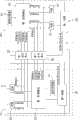
图1是本发明具有风扇冗余控制功能的电子设备的较佳实施方式的原理框图。FIG. 1 is a functional block diagram of a preferred embodiment of an electronic device with fan redundancy control function according to the present invention.
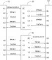
图2是图1的线路连接图。Fig. 2 is a circuit connection diagram of Fig. 1 .
具体实施方式Detailed ways
请参考图1及图2,本发明具有风扇冗余控制功能的电子设备的较佳实施包括一第一电源装置10、一第二电源装置20、一第一开关单元32及一第二开关单元36。所述第一电源装置10及第二电源装置20分别通过一第一电源连接器50及一第二电源连接器60与所述第一开关单元32及第二开关单元36相连。所述第一电源连接器50及第二电源连接器60设置在一背板上,用于给所述电子设备提供电能。所述第一开关单元32及第二开关单元36均是型号为SN74CBT3124DR的总线开关芯片,且均直接设置在所述背板上。所述背板为一电路板,其对设置在其上的元件起到电气连接及支撑固定的作用。在本实施方式中,所述电子设备为一存储系统。Please refer to FIG. 1 and FIG. 2, the preferred implementation of the electronic equipment with fan redundant control function of the present invention includes a first
所述第一电源装置10包括两风扇11和12(第一风扇模块)、一第一控制模块15、一温度传感器16及一第一电源18。所述第一控制模块15与所述风扇11和12及所述第二开关单元36相连,并通过一I2C总线与所述温度传感器16相连。所述温度传感器16用于感测所述电子设备的温度,并将感测到的温度值通过所述I2C总线传输给所述第一控制模块15。所述第一控制模块15根据接收到的温度值来发出第一组控制信息,所述第一组控制信息包括两控制信号PWM1和PWM2及两侦测信号TACH1和TACH2,所述控制信号PWM1和PWM2分别用于控制所述风扇11和12的转速,所述侦测信号TACH1和TACH2分别用于侦测所述风扇11和12的实际转速。所述第一组控制信息被分成两路分别传输给所述风扇11和12及所述第二开关单元36。The first
所述第二电源装置20包括两风扇21和22(第二风扇模块)、一第二控制模块25、一温度传感器26及一第二电源28。所述第二控制模块25与所述风扇21和22及所述第一开关单元32相连,并通过一I2C总线与所述温度传感器26相连。所述温度传感器26用于感测所述电子设备的温度,并将感测到的温度值通过所述I2C总线传输给所述第二控制模块25。所述第二控制模块25根据接收到的温度值来发出第二组控制信息,所述第二组控制信息包括两控制信号PWM3和PWM4及两侦测信号TACH3和TACH4,所述控制信号PWM3和PWM4分别用于控制所述风扇21和22的转速,所述侦测信号TACH3和TACH4分别用于侦测所述风扇21和22的实际转速。所述第二组控制信息被分成两路分别传输给所述风扇21和22及所述第一开关单元32。The second
所述第一电源18与所述风扇11、12、21、22及所述第一控制模块15相连,用于为所述风扇11、12、21、22及所述第一控制模块15提供电源,并发出一控制信号SUM-FAULT-A给所述第一开关单元32,以控制所述第一开关单元32的开启和关闭。所述第二电源28与所述风扇11、12、21、22及所述第二控制模块25相连,用于为所述风扇11、12、21、22及所述第二控制模块25提供电源,并发出一控制信号SUM-FAULT-B给所述第二开关单元36,以控制所述第二开关单元36的开启和关闭。所述风扇11、12、21及22用于给所述电子设备散热。The
所述第一开关单元32包括一使能引脚OE、四个输入引脚C1-C4及分别与所述四个输入引脚C1-C4相对应的四个输出引脚D1-D4,所述第二开关单元36包括一使能引脚OE、四个输入引脚X1-X4及分别与所述四个输入引脚X1-X4相对应的四个输出引脚Y1-Y4,所述第一电源连接器50包括九个引脚A1-A9,所述第二电源连接器60包括九个引脚B1-B9。所述第一开关单元32的使能引脚OE与所述第一电源连接器50的引脚A1相连,用于接收所述引脚A1发出控制信号SUM-FAULT-A;输入引脚C1-C4分别与所述第二电源连接器60的引脚B1-B4相连;用于接收所述引脚B1-B4发出的控制信息PWM3、TACH3、PWM4及TACH4;输出引脚D1-D4分别与所述第一电源连接器50的引脚A2-A5相连,用于将接收到的控制信息PWM3、TACH3、PWM4及TACH4传输给所述引脚A2-A5。所述第二开关单元36的使能引脚OE与所述第二电源连接器60的引脚B5相连,用于接收所述引脚B5发出控制信号SUM-FAULT-B;输入引脚X1-X4分别与所述第一电源连接器50的引脚A6-A9相连,用于接收所述引脚A6-A9发出的控制信息PWM1、TACH1、PWM2及TACH2;输出引脚Y1-Y4分别与所述第二电源连接器60的引脚B6-B9相连,用于将接收到的控制信息PWM1、TACH1、PWM2及TACH2传输给所述引脚B6-B9。其中,所述第一开关单元32只有在其使能引脚OE接收到低电平信号时才处于开启状态,并在开启状态时将从输入引脚C1-C4输入的信号从输出引脚D1-D4对应输出,若其使能引脚OE接收到高电平信号,则所述第一开关单元32处于关闭状态。所述第二开关单元36的工作原理与所述第一开关单元32的工作原理相同,这里不再赘述。The
当所述第一电源18及第二电源28正常工作时,所述风扇11、12、21及22均能正常工作。此时,所述第一电源18及第二电源28发出的控制信号SUM-FAULT-A及SUM-FAULT-B均为高电平信号,所述第一开关单元32的使能引脚OE及所述第二开关单元36的使能引脚OE接收到高电平信号后,所述第一开关单元32及第二开关单元36均处于关闭状态。When the
当所述第一电源18不工作时,所述第一控制模块15因无电源供应而停止工作。此时,所述风扇11和12的电源将仅由所述第二电源28提供。因为所述第一电源18发出的控制信号SUM-FAULT-A由高电平变为低电平,所述第一开关单元32由关闭状态变为开启状态,所述第二控制模块25发出的控制信息PWM3、TACH3及PWM4、TACH4分别经所述第一开关单元32传输给所述风扇11和12,故所述风扇11和12仍能正常工作。When the
当所述第二电源28不工作时,所述第二控制模块25因无电源供应而停止工作。此时,所述风扇21和22的电源将仅由所述第一电源18提供,因为所述第二电源28发出的控制信号SUM-FAULT-B由高电平变为低电平,所述第二开关单元36由关闭状态变为开启状态,所述第一控制模块15发出的控制信息PWM1、TACH1及PWM2、TACH2分别经所述第二开关单元36传输到所述风扇21和22,故所述风扇21和22仍能正常工作。When the
上述具有风扇冗余控制功能的电子设备,通过将所述第一电源18及第二电源28均与所述风扇11、12、21及22相连,并利用所述第一开关单元32及第二开关单元36根据所述第一电源18及第二电源28的工作状态来将控制信息传输给所述风扇11、12及21、22,确保了当电子设备中一个电源装置的电源不工作时,所述电源装置内部的风扇仍能正常工作,所述电子设备内的热量仍能及时被排出。The above-mentioned electronic equipment with fan redundancy control function connects the
Claims (6)
Priority Applications (2)
| Application Number | Priority Date | Filing Date | Title |
|---|---|---|---|
| CN200810304494ACN101673088B (en) | 2008-09-12 | 2008-09-12 | Electronic equipment with redundancy control capability of fan |
| US12/331,398US7800246B2 (en) | 2008-09-12 | 2008-12-09 | Electronic device with redundant fan control function |
Applications Claiming Priority (1)
| Application Number | Priority Date | Filing Date | Title |
|---|---|---|---|
| CN200810304494ACN101673088B (en) | 2008-09-12 | 2008-09-12 | Electronic equipment with redundancy control capability of fan |
Publications (2)
| Publication Number | Publication Date |
|---|---|
| CN101673088Atrue CN101673088A (en) | 2010-03-17 |
| CN101673088B CN101673088B (en) | 2012-10-10 |
Family
ID=42006566
Family Applications (1)
| Application Number | Title | Priority Date | Filing Date |
|---|---|---|---|
| CN200810304494AExpired - Fee RelatedCN101673088B (en) | 2008-09-12 | 2008-09-12 | Electronic equipment with redundancy control capability of fan |
Country Status (2)
| Country | Link |
|---|---|
| US (1) | US7800246B2 (en) |
| CN (1) | CN101673088B (en) |
Cited By (6)
| Publication number | Priority date | Publication date | Assignee | Title |
|---|---|---|---|---|
| CN103064769A (en)* | 2012-12-30 | 2013-04-24 | 长沙湘计海盾科技有限公司 | Dual hot standby server system |
| CN103123535A (en)* | 2011-11-17 | 2013-05-29 | 英业达股份有限公司 | Modular power supply control device |
| CN104747481A (en)* | 2013-12-31 | 2015-07-01 | 鸿富锦精密电子(天津)有限公司 | Fan control system |
| CN104963882A (en)* | 2015-07-07 | 2015-10-07 | 浙江宇视科技有限公司 | Fan module control method and system in dual-control storage system |
| CN104281246B (en)* | 2013-07-11 | 2016-11-30 | 鸿富锦精密电子(天津)有限公司 | Fan power supply circuits |
| CN106871326A (en)* | 2015-12-14 | 2017-06-20 | 阿里巴巴集团控股有限公司 | Computer room, the cooling control system of data center |
Families Citing this family (13)
| Publication number | Priority date | Publication date | Assignee | Title |
|---|---|---|---|---|
| US8120300B2 (en)* | 2008-12-30 | 2012-02-21 | International Business Machines Corporation | Fault tolerant cooling in a redundant power system |
| EP2364807B1 (en)* | 2010-03-10 | 2013-05-08 | Daihen Corporation | Power supply apparatus including fan for air cooling |
| CN102213987B (en)* | 2010-04-06 | 2015-06-10 | 英业达股份有限公司 | Server system and fan detection method thereof |
| FR2965140B1 (en)* | 2010-09-20 | 2013-07-05 | Ece | DEVICE FOR PROTECTING AN ELECTRONIC SYSTEM MOUNTED IN A RACK |
| US9823711B2 (en)* | 2010-09-30 | 2017-11-21 | Seagate Technology Llc | Storage system and a storage bridge bay canister |
| WO2013046248A1 (en)* | 2011-09-26 | 2013-04-04 | Hitachi, Ltd. | Storage system and its control method |
| TW201319791A (en)* | 2011-11-11 | 2013-05-16 | Inventec Corp | Modular power control apparatus |
| WO2013114630A1 (en)* | 2012-02-03 | 2013-08-08 | 富士通株式会社 | Electronic device and control method |
| US9223326B2 (en) | 2012-07-22 | 2015-12-29 | International Business Machines Corporation | Distributed thermal management system for servers |
| KR101394815B1 (en)* | 2012-12-24 | 2014-05-13 | 주식회사 유라코퍼레이션 | Circuit device for power supply rescue of integrated controller |
| CN103899563A (en)* | 2012-12-29 | 2014-07-02 | 鸿富锦精密工业(深圳)有限公司 | Draught fan control system and method |
| CN104750212A (en)* | 2013-12-31 | 2015-07-01 | 鸿富锦精密电子(天津)有限公司 | Fan control system |
| US9901006B2 (en)* | 2015-07-21 | 2018-02-20 | Hong Fu Jin Precision Industry (Shenzhen) Co., Ltd. | Control circuit for fan |
Family Cites Families (5)
| Publication number | Priority date | Publication date | Assignee | Title |
|---|---|---|---|---|
| GB2344939B (en)* | 1998-12-15 | 2000-11-15 | Shin Jiuh Corp | Power supply |
| CN100436831C (en)* | 2001-10-30 | 2008-11-26 | 英业达股份有限公司 | Switching device of heat dissipation system |
| CN2634527Y (en)* | 2003-07-08 | 2004-08-18 | 浪潮电子信息产业股份有限公司 | Computer redundant double power source |
| CN2718645Y (en)* | 2004-07-20 | 2005-08-17 | 保锐科技股份有限公司 | Cooling power supply with computer environment |
| CN100590570C (en)* | 2005-07-15 | 2010-02-17 | 联想(北京)有限公司 | Fan redundant system |
- 2008
- 2008-09-12CNCN200810304494Apatent/CN101673088B/ennot_activeExpired - Fee Related
- 2008-12-09USUS12/331,398patent/US7800246B2/ennot_activeExpired - Fee Related
Cited By (8)
| Publication number | Priority date | Publication date | Assignee | Title |
|---|---|---|---|---|
| CN103123535A (en)* | 2011-11-17 | 2013-05-29 | 英业达股份有限公司 | Modular power supply control device |
| CN103064769A (en)* | 2012-12-30 | 2013-04-24 | 长沙湘计海盾科技有限公司 | Dual hot standby server system |
| CN104281246B (en)* | 2013-07-11 | 2016-11-30 | 鸿富锦精密电子(天津)有限公司 | Fan power supply circuits |
| CN104747481A (en)* | 2013-12-31 | 2015-07-01 | 鸿富锦精密电子(天津)有限公司 | Fan control system |
| CN104963882A (en)* | 2015-07-07 | 2015-10-07 | 浙江宇视科技有限公司 | Fan module control method and system in dual-control storage system |
| CN104963882B (en)* | 2015-07-07 | 2017-08-15 | 浙江宇视科技有限公司 | Blower module control method and system in a kind of dual control storage system |
| CN106871326A (en)* | 2015-12-14 | 2017-06-20 | 阿里巴巴集团控股有限公司 | Computer room, the cooling control system of data center |
| CN106871326B (en)* | 2015-12-14 | 2019-11-26 | 阿里巴巴集团控股有限公司 | Computer room, data center cooling control system |
Also Published As
| Publication number | Publication date |
|---|---|
| CN101673088B (en) | 2012-10-10 |
| US7800246B2 (en) | 2010-09-21 |
| US20100066172A1 (en) | 2010-03-18 |
Similar Documents
| Publication | Publication Date | Title |
|---|---|---|
| CN101673088B (en) | Electronic equipment with redundancy control capability of fan | |
| US7199542B1 (en) | Fan operation adaptive control system | |
| CN202549300U (en) | Hard disk temperature control system | |
| US20110307746A1 (en) | Systems and Methods for Intelligent and Flexible Management and Monitoring of Computer Systems | |
| CN103835972A (en) | Fan rotating speed control system and method for control rotating speed of fan | |
| US20150105910A1 (en) | Server System with Fan controllers | |
| KR102071404B1 (en) | Apparatus and Method for implementing fail safe in Battery Management System | |
| TW201118596A (en) | Server management system | |
| US7615946B2 (en) | Fan speed control device | |
| CN104571273A (en) | Fan controller and server system with the fan controller | |
| CN110469529A (en) | Server fan control system | |
| CN103807199B (en) | Fan control circuitry | |
| US20130138852A1 (en) | Electronic device with baseboard management controller | |
| CN118622748A (en) | A fan control system | |
| CN101472446A (en) | Radiating system and data storage system applying the same | |
| TWI518249B (en) | Fan controller and server system with the fan controller | |
| TWI530776B (en) | Fan controller and server system having the same | |
| CN104750627B (en) | Fan identifying system and server | |
| TWI425328B (en) | Electronic device with redundant control function for fan | |
| CN113126716B (en) | Hard disk backboard and electronic equipment | |
| US20150032284A1 (en) | Detection module, device and system for detecting fan's connection and disconnection states | |
| TWI582604B (en) | External device, electronic device and electronic system | |
| TWI473086B (en) | Computer system | |
| CN101572482A (en) | Power controller with adaptation power supply | |
| CN108089959B (en) | Mainboard detection circuit and electronic device using the mainboard detection circuit |
Legal Events
| Date | Code | Title | Description |
|---|---|---|---|
| C06 | Publication | ||
| PB01 | Publication | ||
| C10 | Entry into substantive examination | ||
| SE01 | Entry into force of request for substantive examination | ||
| C14 | Grant of patent or utility model | ||
| GR01 | Patent grant | ||
| CF01 | Termination of patent right due to non-payment of annual fee | Granted publication date:20121010 Termination date:20140912 | |
| EXPY | Termination of patent right or utility model |