CN101673018B - Solar photoelectric electrochromic device - Google Patents
Solar photoelectric electrochromic deviceDownload PDFInfo
- Publication number
- CN101673018B CN101673018BCN2008102129539ACN200810212953ACN101673018BCN 101673018 BCN101673018 BCN 101673018BCN 2008102129539 ACN2008102129539 ACN 2008102129539ACN 200810212953 ACN200810212953 ACN 200810212953ACN 101673018 BCN101673018 BCN 101673018B
- Authority
- CN
- China
- Prior art keywords
- thin film
- film solar
- electrochromic
- electrochromic device
- photoelectric
- Prior art date
- Legal status (The legal status is an assumption and is not a legal conclusion. Google has not performed a legal analysis and makes no representation as to the accuracy of the status listed.)
- Expired - Fee Related
Links
Images


Classifications
- Y—GENERAL TAGGING OF NEW TECHNOLOGICAL DEVELOPMENTS; GENERAL TAGGING OF CROSS-SECTIONAL TECHNOLOGIES SPANNING OVER SEVERAL SECTIONS OF THE IPC; TECHNICAL SUBJECTS COVERED BY FORMER USPC CROSS-REFERENCE ART COLLECTIONS [XRACs] AND DIGESTS
- Y02—TECHNOLOGIES OR APPLICATIONS FOR MITIGATION OR ADAPTATION AGAINST CLIMATE CHANGE
- Y02E—REDUCTION OF GREENHOUSE GAS [GHG] EMISSIONS, RELATED TO ENERGY GENERATION, TRANSMISSION OR DISTRIBUTION
- Y02E10/00—Energy generation through renewable energy sources
- Y02E10/50—Photovoltaic [PV] energy
Landscapes
- Photovoltaic Devices (AREA)
- Electrochromic Elements, Electrophoresis, Or Variable Reflection Or Absorption Elements (AREA)
Abstract
Description
Translated fromChinese【技术领域】【Technical field】
本发明涉及一种电致变色器件(electrochromic device,ECD),特别是涉及一种太阳光电电致变色器件(solar photovoltaic electrochromic device)。The present invention relates to an electrochromic device (electrochromic device, ECD), particularly relates to a kind of solar photoelectric electrochromic device (solar photovoltaic electrochromic device).
【背景技术】【Background technique】
所谓的电致变色器件是由导电物质组成的、可通过施加电场或电流引起可逆的氧化/还原(redox)反应而产生颜色变化的器件,电致变色器件的制作需满足下列几种特性,包括:不同电位下所呈现的颜色必须能够很容易分辨,颜色的变化快速且均一,器件颜色的可逆变化需能够重复上万次以上,以及稳定性高。常见的电致变色器件包括表面限制薄膜型(surfaceconfined thin film)电致变色器件以及溶液型电致变色器件。The so-called electrochromic device is a device composed of conductive substances that can cause a reversible oxidation/reduction (redox) reaction by applying an electric field or current to produce a color change. The fabrication of an electrochromic device needs to meet the following characteristics, including : The colors presented at different potentials must be easily distinguishable, the color changes quickly and uniformly, the reversible change of the device color must be able to repeat tens of thousands of times, and have high stability. Common electrochromic devices include surface confined thin film electrochromic devices and solution electrochromic devices.
表面限制薄膜型电致变色器件的结构是由上、下两层透明基材加上位于其间的电致变色多层膜所组成。其中电致变色多层膜类似于电池的结构,至少含有五层不同功能的涂/镀层。上述五层涂/镀层依次为透明导电层、电致变色层、电解质层、离子储存层以及透明导电层。溶液型电致变色器件的结构则比较简单,由上、下两个透明导电基材组成,通过环氧树脂胶以电极层相向的方式贴合两面基材,其间配置电致变色有机溶液,溶液的成分包含氧化或还原型电致变色有机小分子材料、高分子电解质以及溶剂。The structure of the surface-limited thin-film electrochromic device is composed of upper and lower layers of transparent substrates and an electrochromic multilayer film in between. Among them, the electrochromic multilayer film is similar to the structure of a battery, and contains at least five layers of coating/plating layers with different functions. The above five layers of coating/plating are sequentially a transparent conductive layer, an electrochromic layer, an electrolyte layer, an ion storage layer and a transparent conductive layer. The structure of the solution-type electrochromic device is relatively simple. It consists of two transparent conductive substrates, the upper and the lower. The two substrates are bonded by epoxy resin glue in the way that the electrode layers face each other, and the electrochromic organic solution is placed in between. The components include oxidized or reduced electrochromic organic small molecule materials, polymer electrolytes and solvents.
虽然电致变色技术历经多年的研究,但至今只有电致变色后视镜被商业化,其它大面积电致变色器件100仍然无法有效地克服变色不均匀的虹膜效应(iris effect),如图1所示。这样的现象可以图2作说明,在图2中显示一般电致变色器件200,其由两面透明导电基材210与夹在两透明导电基材210之间的电致变色溶液220组成。通电时电源分别从两面透明导电基材210的电极230四周供应,但由于电致变色器件200平面中心与边缘的电场路径长短不同,造成边缘区域和中心区域之间的阻抗有明显的差异。而阻抗的差异则导致如图1所示,变色浓度由边缘起至中心区域呈现同心椭圆形梯度变化,影响变色效果的均匀度。Although electrochromic technology has been researched for many years, only electrochromic rearview mirrors have been commercialized so far, and other large-area
为拓展电致变色技术的应用范围,已有多项结合光电技术与太阳能电池的相关研究提供了更多样化的方向。例如整合在建筑物内的太阳能电池(building integrated photovoltaic,BIPV)可以配合电致变色技术,在不用额外提供电源的情况下,根据室内外光照强度的变化,自动调整电致变色窗颜色的深浅,减少室内热能。由于节能意识的抬头,此应用方法已成为一种新的趋势。In order to expand the application range of electrochromic technology, a number of related researches combining photoelectric technology and solar cells have provided more diversified directions. For example, solar cells (building integrated photovoltaic, BIPV) integrated in buildings can cooperate with electrochromic technology to automatically adjust the color depth of electrochromic windows according to changes in indoor and outdoor light intensity without additional power supply. Reduce indoor heat energy. Due to the rising awareness of energy saving, this application method has become a new trend.
例如美国专利US 5,377,037揭示了一种整合了硅薄膜太阳能电池与变色物质的电致变色器件。其结构为在两面透明导电玻璃基材之间,依次设置堆栈型(tandem)结构的硅薄膜太阳能电池、电致变色器件以及电解质层。最后并以分压器电阻串联位于堆栈结构两面最外层的透明导电玻璃基材,以控制调整硅薄膜太阳能电池作用时驱动电致变色器件的电压,故无须外部电源即可控制变色。然而,此两面电极结构虽可整合电致变色器件与太阳能电池,但由于无机材质变色所需的电荷密度(charge density)相当大,需要比较大的电压来驱动变色,无可避免需应用较厚的本质层(intrinsiclayer),来提高光电转换效率,甚至应用多层堆栈(tandem)以提高硅薄膜太阳能电池的开路电压(Voc)。如此硅薄膜太阳能电池的透射比便因而降低。另外,由于电源由电极边缘供应,仍然会有虹膜效应发生。For example, U.S. Patent No. 5,377,037 discloses an electrochromic device integrating a silicon thin-film solar cell and a color-changing substance. Its structure is that a silicon thin-film solar cell, an electrochromic device and an electrolyte layer of a stacked (tandem) structure are sequentially arranged between two transparent conductive glass substrates. Finally, a voltage divider resistor is connected in series with the transparent conductive glass substrates located on the outermost layers of both sides of the stack structure to control and adjust the voltage driving the electrochromic device when the silicon thin film solar cell works, so the discoloration can be controlled without an external power supply. However, although this two-sided electrode structure can integrate electrochromic devices and solar cells, because the charge density required for color change of inorganic materials is quite large, a relatively large voltage is required to drive the color change, and it is unavoidable to use a thicker electrode. The intrinsic layer (intrinsiclayer) to improve photoelectric conversion efficiency, and even the application of multi-layer stack (tandem) to improve the open circuit voltage (Voc) of silicon thin film solar cells. Thus, the transmittance of the silicon thin film solar cell is thus reduced. Also, since power is supplied from the edge of the electrode, there will still be an iris effect.
【发明内容】【Content of invention】
本发明提供一种太阳光电电致变色器件,具有均匀地改变颜色的效果,并具有较高的透射比(transmittance)。The invention provides a solar photoelectric electrochromic device, which has the effect of uniformly changing colors and has high transmittance.
本发明提供一种太阳光电电致变色器件,该器件包括半透明薄膜太阳能电池基材、电致变色溶液以及透明非导电基材,其中,电致变色溶液位于透明非导电基材与半透明薄膜太阳能电池基材之间。半透明薄膜太阳能电池基材包括透明基材和多个薄膜太阳能电池,这些薄膜太阳能电池的正极和负极同时作为太阳光电电致变色器件的正极及负极。The invention provides a solar photoelectric electrochromic device, which comprises a translucent film solar cell substrate, an electrochromic solution and a transparent non-conductive substrate, wherein the electrochromic solution is located between the transparent non-conductive substrate and the translucent film between solar cell substrates. The semi-transparent thin-film solar cell substrate includes a transparent substrate and a plurality of thin-film solar cells, and the positive and negative electrodes of these thin-film solar cells simultaneously serve as the positive and negative electrodes of the solar photoelectric electrochromic device.
在本发明的一种实施方案中,上述太阳光电电致变色器件还包括与各薄膜太阳能电池相连接的输出开关配置,以控制由薄膜太阳能电池提供的电流输出。In one embodiment of the present invention, the solar photoelectric electrochromic device further includes an output switch configuration connected to each thin film solar cell to control the current output provided by the thin film solar cell.
在本发明的一种实施方案中,上述薄膜太阳能电池可以并联或串联至该输出开关配置。In one embodiment of the present invention, the thin film solar cells described above may be connected in parallel or in series to the output switch configuration.
在本发明的另一实施方案实施例中,上述输出开关配置还可连接至直流/交流转换装置,由此将薄膜太阳能电池提供的电流转换为市电(交流电)。此外,上述输出开关配置还可连接至直流电荷储存装置,以储存薄膜太阳能电池提供的直流电流。In another implementation example of the present invention, the above-mentioned output switch configuration can also be connected to a DC/AC conversion device, thereby converting the current provided by the thin-film solar cell into commercial power (AC power). In addition, the above-mentioned output switch configuration can also be connected to a DC charge storage device to store the DC current provided by the thin film solar cell.
在本发明的一种实施方案中,上述的薄膜太阳能电池例如是呈矩阵排列或条状排列的。In one embodiment of the present invention, the above-mentioned thin-film solar cells are, for example, arranged in a matrix or strips.
在本发明的一种实施方案中,上述的电致变色溶液的成分包括氧化/还原型有机小分子电致变色材料以及溶剂。其中,前述氧化/还原型有机小分子电致变色材料选自负极变色材料以及正极变色材料中的一种或及其组合。其中,负极变色材料例如甲基紫精(methyl viologen)、乙基紫精(ethylviologen)、苯基紫精(benzyl viologen)或丙基紫精(propyl viologen)等;正极变色材料例如二甲基吩嗪(dimethylphenazine)或苯二胺(phenylenediamine)等。In one embodiment of the present invention, the components of the electrochromic solution include an oxidation/reduction organic small molecule electrochromic material and a solvent. Wherein, the aforementioned oxidation/reduction organic small molecule electrochromic material is selected from one or a combination of negative electrode color-changing materials and positive electrode color-changing materials. Among them, negative electrode color-changing materials such as methyl viologen (methyl viologen), ethyl viologen (ethylviologen), phenyl viologen (benzyl viologen) or propyl viologen (propyl viologen) etc.; positive electrode color-changing materials such as dimethyl phen Dimethylphenazine or phenylenediamine, etc.
在本发明的一种实施方案中,上述电致变色溶液中的溶剂例如碳酸异丙烯酯(propylene carbonate)、碳酸亚乙酯(ethylene carbonate)、γ-丁内酯(γ-butyrolactone)、乙腈(acetonitrile)、四氢呋喃(tetrahydrofuran,THF)或甲基吡咯烷酮(N-methyl-2-pyrrolidone,NMP)等。In one embodiment of the present invention, the solvent in the above-mentioned electrochromic solution is for example propylene carbonate (propylene carbonate), ethylene carbonate (ethylene carbonate), γ-butyrolactone (γ-butyrolactone), acetonitrile ( acetonitrole), tetrahydrofuran (tetrahydrofuran, THF) or methyl pyrrolidone (N-methyl-2-pyrrolidone, NMP), etc.
在本发明的另一实施方案中,上述电致变色溶液的成分还可包括碱金属盐(alkali metal salt),例如三氟甲磺酸锂(lithium triflate)、高氯酸锂(lithiumperchlorate),或四烷基铵盐(tetra alkyl ammonium salt)等。In another embodiment of the present invention, the composition of the above-mentioned electrochromic solution may also include alkali metal salt (alkali metal salt), such as lithium triflate (lithium triflate), lithium perchlorate (lithium perchlorate), or Tetra alkyl ammonium salt, etc.
在本发明的另一实施方案中,上述电致变色溶液的成分还可包括高分子电解质,例如聚环氧乙烷(polyethylene oxide)、聚环氧丙烷(polypropyleneoxide)或聚甲基丙烯酸甲酯(polymethylmetha acrylate)。In another embodiment of the present invention, the composition of the above-mentioned electrochromic solution may also include a polymer electrolyte, such as polyethylene oxide (polyethylene oxide), polypropylene oxide (polypropylene oxide) or polymethyl methacrylate ( polymethylmetha acrylate).
在本发明的另一实施方案中,上述电致变色材料的氧化/还原电位例如小于3V。In another embodiment of the present invention, the oxidation/reduction potential of the above-mentioned electrochromic material is, for example, less than 3V.
在本发明的一种实施方案中,上述半透明薄膜太阳能电池基材包括覆板(superstrate)或底板(substrate)结构的薄膜太阳能电池基材。In one embodiment of the present invention, the above-mentioned translucent thin film solar cell substrate includes a thin film solar cell substrate with superstrate or substrate structure.
在本发明的一种实施方案中,上述薄膜太阳能电池包括硅薄膜太阳能电池、铜铟镓硒(CIGS)薄膜太阳能电池或镉碲(CdTe)薄膜太阳能电池。In one embodiment of the present invention, the above-mentioned thin film solar cell includes a silicon thin film solar cell, a copper indium gallium selenide (CIGS) thin film solar cell or a cadmium tellurium (CdTe) thin film solar cell.
在本发明的一种实施方案中,上述太阳光电电致变色器件还包括多个薄膜晶体管(thin film transistor,TFT),用以主动控制薄膜太阳能电池。In one embodiment of the present invention, the solar photoelectric electrochromic device further includes a plurality of thin film transistors (thin film transistor, TFT), which are used to actively control the thin film solar cells.
本发明因采用在同一面基板上以例如矩阵排列或条状排列的方式分散配置薄膜太阳能电池,可使器件变色均匀。此外,本发明因电致变色溶液所需的氧化/还原电位较低,因此薄膜太阳能电池发电量需求降低,故可减少太阳能电池的构成材料或厚度,而增加整体器件的透射比。In the present invention, the thin-film solar cells are scattered and arranged on the same substrate in a matrix arrangement or a strip arrangement, so that the color of the device can be changed uniformly. In addition, because the oxidation/reduction potential required by the electrochromic solution is lower in the present invention, the power generation requirement of the thin-film solar cell is reduced, so the constituent materials or thickness of the solar cell can be reduced, and the transmittance of the overall device can be increased.
为让本发明上述特征和优点能更明显易懂,下文特举优选实施方案,并配合所附图式,作详细说明如下。In order to make the above-mentioned features and advantages of the present invention more comprehensible, the preferred embodiments are specifically cited below, together with the accompanying drawings, and described in detail as follows.
【附图说明】【Description of drawings】
图1是已知的虹膜效应的平面示意图。Fig. 1 is a schematic plan view of the known iris effect.
图2是已知的电致变色器件结构的立体示意图。Fig. 2 is a three-dimensional schematic view of the structure of a known electrochromic device.
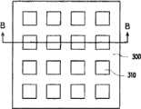
图3A是依照本发明的一个优选实施方案的一种太阳光电电致变色器件的俯视示意图。Fig. 3A is a schematic top view of a solar photoelectric electrochromic device according to a preferred embodiment of the present invention.
图3B是图3A中B-B切面的剖面示意图。Fig. 3B is a schematic cross-sectional view of the B-B section in Fig. 3A.
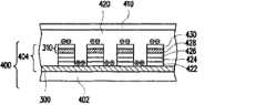
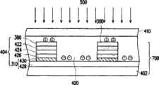
图4是图3B太阳光电电致变色器件的立体示意图。Fig. 4 is a perspective view of the solar photoelectric electrochromic device in Fig. 3B.
图5是电致变色溶液的电致变色循环伏安(cyclic voltagram)曲线图。Fig. 5 is a graph of electrochromic cyclic voltammetry (cyclic voltagram) of the electrochromic solution.
图6是实验例所用的半透明薄膜太阳能电池基材的剖面示意图。Fig. 6 is a schematic cross-sectional view of a translucent thin-film solar cell substrate used in an experimental example.
图7是依照本发明第二实施方案的一种太阳光电电致变色器件的俯视示意图。Fig. 7 is a schematic top view of a solar photoelectric electrochromic device according to the second embodiment of the present invention.
图8为依照本发明第三实施方案所示的一种太阳光电电致变色器件的俯视示意图。Fig. 8 is a schematic top view of a solar photoelectric electrochromic device according to the third embodiment of the present invention.
图9是依照本发明第四实施方案所示的一种太阳光电电致变色器件的另一种变形的俯视示意图。Fig. 9 is a schematic top view of another modification of a solar photoelectric electrochromic device according to the fourth embodiment of the present invention.
图10是图9的太阳光电电致变色器件的另一种变形的俯视示意图。FIG. 10 is a schematic top view of another modification of the solar photoelectric electrochromic device in FIG. 9 .
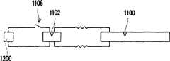
图11是图9的太阳光电电致变色器件与一种输出开关配置之间的电路示意图。FIG. 11 is a schematic circuit diagram between the solar photoelectric electrochromic device of FIG. 9 and an output switch configuration.
图12是图9的太阳光电电致变色器件与另一种输出开关配置之间的电路示意图。FIG. 12 is a schematic circuit diagram between the solar photoelectric electrochromic device of FIG. 9 and another output switch configuration.
图13是图9的太阳光电电致变色器件与薄膜晶体管的电路示意图。FIG. 13 is a schematic circuit diagram of the solar photoelectric electrochromic device and the thin film transistor in FIG. 9 .
【主要器件标号说明】【Description of the main components label】
100、200、1100:电致变色器件100, 200, 1100: Electrochromic devices
210:透明导电基材210: transparent conductive substrate
220、420:电致变色溶液220, 420: Electrochromic solution
230:电极230: electrode
300、300a、300b、300c、300d:正极300, 300a, 300b, 300c, 300d: positive electrode
310、310a、310b、310c、310d:负极310, 310a, 310b, 310c, 310d: Negative electrode
400、700、800:半透明薄膜太阳能电池基材400, 700, 800: Translucent thin-film solar cell substrates
402:透明基材402: transparent substrate
404:硅薄膜太阳能电池404: Silicon thin film solar cells
410:透明非导电基材410: transparent non-conductive substrate
422:P型层422: P-type layer
424:本质层424: Essence layer
426:N型层426: N-type layer
428:透明导电氧化物层428: transparent conductive oxide layer
430:金属层430: metal layer
500:太阳光500: sunlight
600:玻璃基材600: glass substrate
602、610:ZnO:Al层602, 610: ZnO: Al layer
604:p型层604: p-type layer
606:a-SiH层606: a-SiH layer
608:n型层608: n-type layer
612:Ag层612: Ag layer
802:铜铟镓硒(CIGS)薄膜太阳能电池802: Copper Indium Gallium Selenide (CIGS) Thin Film Solar Cell
804:CIGS吸收层804: CIGS absorbing layer
806:缓冲层806: buffer layer
900:输出开关配置900: output switch configuration
1102:薄膜太阳能电池1102: Thin Film Solar Cell
1104:直流/交流转换装置1104: DC/AC conversion device
1106:开关1106: switch
1108:市电1108: mains electricity
1200:直流电荷储存装置1200: DC charge storage device
1300:薄膜晶体管1300: thin film transistor
【具体实施方式】【Detailed ways】
图3A为依照本发明第一实施方案所绘制的太阳光电电致变色器件的俯视示意图,图3B为图3A中B-B切面的剖面示意图。Fig. 3A is a schematic top view of a solar photoelectric electrochromic device drawn according to the first embodiment of the present invention, and Fig. 3B is a schematic cross-sectional view of a section B-B in Fig. 3A.
请同时参照图3A与图3B,本实施方案的太阳光电电致变色器件是由半透明薄膜太阳能电池基材400、透明非导电基材410以及电致变色溶液420所组成。电致变色溶液420位于半透明薄膜太阳能电池基材400与透明非导电基材410之间,而组成一种单面导电基材的太阳光电电致变色器件。如图4所示,半透明薄膜太阳能电池基材400为一种覆板(superstrate)结构的薄膜太阳能电池基材,包括透明基材402与多个硅薄膜太阳能电池404,其中透明基材402的材料为例如玻璃、塑料或其它适合的透明可挠性基材。透明非导电基材410的材料则例如是玻璃、塑料或可挠性基材。至于硅薄膜太阳能电池404是由例如正极300、P型层422、本质层424、N型层426以及负极310组成。其中正极300的材料例如透明导电氧化物(transparentconductive oxide,TCO)。负极310则可包括一层透明导电氧化物层428及一层金属层430,且负极310的透明导电氧化物层428直接接触N型层426。Please refer to FIG. 3A and FIG. 3B at the same time. The solar photoelectric electrochromic device of this embodiment is composed of a translucent thin film
在本实施方案中,电致变色溶液420的成分例如有氧化/还原型有机小分子电致变色材料以及溶剂,而形成一种溶液。其中氧化/还原型有机小分子电致变色材料例如是选自负极变色材料以及正极变色材料中的一种或及其组合。前述负极变色材料例如甲基紫精、乙基紫精、苯基紫精或丙基紫精等;正极变色材料例如二甲基吩嗪或苯二胺等,且其氧化/还原电位皆小于3V。此外,电致变色溶液420的成分还可包括碱金属盐,例如三氟甲基磺酸锂、高氯酸锂或四烷基铵盐等。另外,在电致变色溶液420中还包括适当添加量的高分子电解质,以提高电致变色溶液420的黏度;例如聚环氧乙烷、聚环氧丙烷或聚甲基丙烯酸甲酯等。而电致变色溶液420中的溶剂则例如碳酸异丙烯酯、碳酸亚乙酯、γ-丁内酯、乙腈、四氢呋喃或甲基吡咯烷酮。In this embodiment, the components of the
上述正极300与负极310不但是硅薄膜太阳能电池404的正极与负极,也同时作为本实施例的太阳光电电致变色器件的正极与负极。如图4所示,其为图3B的太阳光电电致变色器件的立体示意图,当太阳光500由半透明薄膜太阳能电池基材400表面进入太阳光电电致变色器件时,薄膜太阳能电池(请见图4的404)立刻产生电子-空穴对。在发电状态下薄膜太阳能电池所产生的电流,经由正极300与负极310被输送到电致变色溶液420里,使原本处于透明无色状态的电致变色溶液420发生氧化/还原反应,此时的正极300、负极310以及电致变色溶液420即组成电致变色器件。在负极310处获得薄膜太阳能电池所释放的电子后,负极变色材料发生还原反应并变色。而正极变色材料在正极300处获得薄膜太阳能电池所释放的空穴而发生氧化反应并变色。The
当太阳光强度减弱,薄膜太阳能电池所产生的电子、空穴渐渐变少,太阳光电电致变色器件的驱动电压逐渐消失,在负极310表面的负极变色材料即从有色还原态逐步褪色,而变回透明呈无色氧化态。在正极300表面的正极变色材料从有色氧化态逐步褪色,而变成透明无色还原态。而由于薄膜太阳能电池产生的电流在电致变色溶液420中被转换成离子流,因此通电后,虽然正极300、负极310同时接触电致变色溶液420,但并不会有短路问题发生。为了达到电致变色时正负极的氧化/还原反应电荷平衡,正极300与负极310的面积比率要接近。When the sunlight intensity weakens, the electrons and holes generated by the thin-film solar cell gradually decrease, the driving voltage of the solar photoelectric electrochromic device gradually disappears, and the negative electrode color-changing material on the surface of the
在本实施方案中,电致变色溶液420仅需低电压低电流即可驱动变色。举例来说,可先将0.05克的甲基紫精二氯化物溶于5毫升纯水内,并充分搅拌以配成均匀无色的电致变色溶液。上述甲基紫精二氯化物是指1,1’-二甲基-4,4’-联吡啶鎓二氯化物(1,1’-dimethyl-4,4’-bipyridinium dichloride),其结构式如下所示:In this embodiment, the

接着,将此电致变色溶液涂布在面积2cm×2cm铟锡氧化物(indium tinoxide,ITO)导电玻璃基材上,再覆盖上另一面铟锡氧化物导电玻璃基材,组成电致变色器件。将此电致变色器件的正、负极接到电化学分析仪,由-1V到3V进行循环伏安(cyclic voltammogram,CV)扫描。其扫瞄结果如图5循环伏安曲线图所示,在+0.16V处就开始产生还原反应。一般有机小分子的氧化/还原电位都相当低,以紫精类负极变色材料为例,电荷密度达2mC/cm2已足于产生明显的彩色对比。Next, apply the electrochromic solution on an indium tin oxide (ITO) conductive glass substrate with an area of 2cm×2cm, and then cover the other side of the indium tin oxide conductive glass substrate to form an electrochromic device. . Connect the positive and negative electrodes of the electrochromic device to an electrochemical analyzer, and perform cyclic voltammetry (cyclic voltammogram, CV) scanning from -1V to 3V. The scanning result is shown in the cyclic voltammetry curve in Figure 5, and the reduction reaction begins at +0.16V. Generally, the oxidation/reduction potential of small organic molecules is quite low. Taking viologen negative electrode color-changing materials as an example, a charge density of 2mC/cm2 is enough to produce obvious color contrast.
请再度参照图3B,由于电致变色溶液420的氧化/还原电位不高,以及变色所需的电荷密度不高,因此当薄膜太阳能电池404的效能足以发生电致变色时,可单独由透明导电氧化物层428构成负极310,而且本质层424的厚度可以降低,使整体太阳光电电致变色器件的透射比增加。Please refer to FIG. 3B again. Since the oxidation/reduction potential of the
以下通过实验例来证实本实施方案的太阳光电电致变色器件的可行性。The feasibility of the solar photoelectric electrochromic device of this embodiment will be verified through the following experimental examples.
实验例1Experimental example 1
先准备透明玻璃基材。另外将0.05克高氯酸锂以及0.05克甲基紫精(1,1’-dimethyl-4,4’-bipyridinium dichloride,1,1’-二甲基-4,4’-联吡啶鎓二氯化物)溶于5毫升纯水内,并搅拌配成均匀透明无色的电致变色溶液。将该电致变色溶液涂布于上述透明玻璃基材上,再将面积为15cm×15cm的半透明薄膜太阳能电池基材以环氧树脂胶贴合于透明玻璃基材。其中所使用的是硅薄膜太阳能电池,且硅薄膜太阳能电池呈矩阵排列,单一矩阵面积约为0.25cm2。而上述环氧树脂胶的厚度约为0.5厘米,并混合有玻璃球作为间隙物,使两个基材产生一定的间距。Prepare the transparent glass substrate first. In addition, 0.05 grams of lithium perchlorate and 0.05 grams of methyl viologen (1,1'-dimethyl-4,4'-bipyridinium dichloride, 1,1'-dimethyl-4,4'-bipyridinium dichloride compound) was dissolved in 5 milliliters of pure water and stirred to form a uniform, transparent and colorless electrochromic solution. The electrochromic solution was coated on the above-mentioned transparent glass substrate, and then the translucent thin-film solar cell substrate with an area of 15 cm×15 cm was attached to the transparent glass substrate with epoxy glue. The silicon thin-film solar cells are used, and the silicon thin-film solar cells are arranged in a matrix, and the area of a single matrix is about 0.25 cm2 . The thickness of the above-mentioned epoxy resin glue is about 0.5 cm, and glass balls are mixed therein as spacers to make a certain distance between the two base materials.
其中,所用的半透明薄膜太阳能电池基材可以采用溅射方法形成:在15cm×15cm的玻璃基材上生长一层透明导电层,再以电浆辅助化学气相沉积法再透明导电玻璃层上进行硅薄膜的连续镀膜,最后在硅薄膜层上沉积透明导电层以及金属镀膜。再以532nm脉冲激光将上述部分硅薄膜镀层剥除,得到矩阵状的硅薄膜太阳能电池,其中负极方块为面积等于0.5cm×0.5cm的硅薄膜镀层,方块以外的区域皆为正极,且负极方块与负极方块之间的间隔为0.2cm,总负极方块数目为196个。其结构如图6所示,包括:面积为15×15cm2的玻璃基材600;作为正极的ZnO:Al层602,其厚度为10nm;p型层604,其厚度为30nm;作为本质层的a-SiH层606,其厚度为450nm;n型层608,其厚度为30nm;80nm厚的ZnO:Al层610和300nm厚的Ag层612,两者构成负极。Among them, the semi-transparent thin-film solar cell substrate used can be formed by sputtering: a layer of transparent conductive layer is grown on a glass substrate of 15cm×15cm, and then plasma-assisted chemical vapor deposition is carried out on the transparent conductive glass layer. Continuous coating of silicon thin film, finally depositing a transparent conductive layer and metal coating on the silicon thin film layer. Then use a 532nm pulsed laser to peel off the above part of the silicon thin film coating to obtain a matrix silicon thin film solar cell. The distance between the negative square and the negative square is 0.2cm, and the total number of negative squares is 196. Its structure is shown in Figure 6, including: a glass substrate 600 with an area of 15×15cm2 ; a ZnO:Al layer 602 as the positive electrode, with a thickness of 10nm; a p-type layer 604, with a thickness of 30nm; The a-SiH layer 606 has a thickness of 450nm; the n-type layer 608 has a thickness of 30nm; an 80nm thick ZnO:Al layer 610 and a 300nm thick Ag layer 612 constitute the negative electrode.
半透明薄膜太阳能电池的开路电压Voc为0.6V,电流密度Jsc为5mA/cm2以及Pmax为0.5mW。因此,当太阳光照射太阳光电电致变色器件时,在30秒钟时间内,电致变色溶液在负极的正下方开始产生变色,由透明无色逐渐变成浅蓝色,再变成深蓝色。当太阳光停止照射,太阳光电电致变色器件在15秒内又恢复变成透明色。The open circuit voltage Voc of the semitransparent thin film solar cell is 0.6V, the current density Jsc is 5mA/cm2 and the Pmax is 0.5mW. Therefore, when sunlight irradiates the solar photoelectric electrochromic device, within 30 seconds, the electrochromic solution begins to change color directly under the negative electrode, from transparent and colorless to light blue and then dark blue. . When the sunlight stops shining, the solar photoelectric electrochromic device returns to transparent color within 15 seconds.
实验例2Experimental example 2
先准备透明玻璃基材。另外将0.05克5,10-二氢-5,10-二甲基吩嗪(5,10-dihydro-5,10-dimethyl phenazine)溶于5毫升碳酸异丙烯酯(propylenecarbonate)溶剂内,并搅拌配成均匀透明无色的电致变色溶液。将该电致变色溶液涂布于上述透明玻璃基材上,再将面积为15cm×15cm的半透明薄膜太阳能电池基材以环氧树脂胶贴合于透明玻璃基材。其中所使用的是呈矩阵排列的硅薄膜太阳能电池,单一矩阵面积约为0.25cm2,其结构与实施例1相同。而上述环氧树脂胶的厚度约为0.5厘米,并混合有玻璃球作为间隙物,使两个基材产生一定的间距。Prepare the transparent glass substrate first. In addition, 0.05 g of 5,10-dihydro-5,10-dimethylphenazine (5,10-dihydro-5,10-dimethylphenazine) was dissolved in 5 ml of propylene carbonate (propylenecarbonate) solvent, and stirred Dubbed into a uniform, transparent and colorless electrochromic solution. The electrochromic solution was coated on the above-mentioned transparent glass substrate, and then the translucent thin-film solar cell substrate with an area of 15 cm×15 cm was attached to the transparent glass substrate with epoxy glue. The silicon thin-film solar cells arranged in a matrix are used, the area of a single matrix is about 0.25 cm2 , and its structure is the same as that of the first embodiment. The thickness of the above-mentioned epoxy resin glue is about 0.5 cm, and glass balls are mixed therein as spacers to make a certain distance between the two base materials.
半透明薄膜太阳能电池的开路电压Voc为0.62V,电流密度Jsc为5.2mA/cm2以及Pmax为0.55mW。因此,当太阳光照射太阳光电电致变色器件时,在40秒钟时间内,电致变色溶液在正极的正下方开始产生变色,由透明浅黄色逐渐变成黄色,再变成绿色。当太阳光停止照射,太阳光电电致变色器件在20秒内又恢复变成透明浅黄色。The open circuit voltage Voc of the semitransparent thin film solar cell is 0.62V, the current density Jsc is 5.2mA/cm2 and the Pmax is 0.55mW. Therefore, when sunlight irradiates the solar photoelectric electrochromic device, within 40 seconds, the electrochromic solution starts to change color directly under the positive electrode, gradually changing from transparent light yellow to yellow and then to green. When the sunlight stops shining, the solar photoelectric electrochromic device returns to transparent light yellow within 20 seconds.
图7为依照本发明第二实施实施方案所示的一种太阳光电电致变色器件的俯视示意图,其中使用与第一实施方案相同的标号来代表相同的部件。请参照图7,第二实施方案的太阳光电电致变色器件是由半透明薄膜太阳能电池基材700、电致变色溶液420、透明非导电基材410所组成。上述半透明薄膜太阳能电池基材700为一种底板(substrate)结构的薄膜太阳能电池基材(太阳光500从透明非导电基材410入射),包括硅薄膜太阳能电池404和透明基材402。至于硅薄膜太阳能电池404是由负极310、N型层426、本质层424、P型层422以及正极300组成。其中正极300的材料为例如透明导电氧化物(TCO),负极310则可包括一层透明导电氧化物层428及位于N型层426与透明导电氧化物层428之间的金属层430。由于半透明薄膜太阳能电池基材700属于底板结构的薄膜太阳能电池基材,所以电致变色溶液420的变色情况有可能影响硅薄膜太阳能电池404产生电的条件,因此第二实施方案的太阳光电电致变色器件可应用于需要循环式变色的器件。Fig. 7 is a schematic top view of a solar photoelectric electrochromic device according to the second embodiment of the present invention, wherein the same symbols as those in the first embodiment are used to denote the same components. Please refer to FIG. 7 , the solar photoelectric electrochromic device of the second embodiment is composed of a translucent thin-film
图8为依照本发明第三实施方案所示的一种太阳光电电致变色器件的俯视示意图,其中使用与第二实施方案相同的标号来代表相同的部件。请参照图8,第三实施方案的太阳光电电致变色器件与第二实施方案最大的差异在于,半透明薄膜太阳能电池基材800包括透明基材402与多个铜铟镓硒(CIGS)薄膜太阳能电池802,其中CIGS薄膜太阳能电池802是由例如正极300、CIGS吸收层(absorber layer)804、缓冲层(buffer layer)806以及负极310组成。其中正极300与负极310的材料为例如透明导电氧化物(TCO)。此外,镉碲(CdTe)薄膜太阳能电池同样适用于第三实施方案的薄膜太阳能电池。Fig. 8 is a schematic top view of a solar photoelectric electrochromic device according to the third embodiment of the present invention, wherein the same symbols as those in the second embodiment are used to denote the same components. Please refer to FIG. 8, the biggest difference between the solar photoelectric electrochromic device of the third embodiment and the second embodiment is that the semi-transparent thin-film
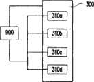
图9为依照本发明第四实施方案所示的一种太阳光电电致变色器件的俯视示意图。请参照图9,本实施方案的太阳光电电致变色器件除了上述各实施方案中的半透明薄膜太阳能电池基材(如图4的400、图7的700、图8的800)、电致变色溶液(如图4的420)以及透明非导电基材(如图4的410)之外,还包括与薄膜太阳能电池(如图4的404、图8的802等)相连接的输出开关配置900,藉由连接其正极300与负极310来控制薄膜太阳能电池404的电流输出。有关本实施方案的太阳光电电致变色器件中的构件,可参照上面实施方案所描述,故不再赘述。Fig. 9 is a schematic top view of a solar photoelectric electrochromic device according to the fourth embodiment of the present invention. Please refer to Fig. 9, the solar photoelectric electrochromic device of the present embodiment except the translucent thin-film solar cell substrate (400 of Fig. 4, 700 of Fig. 7, 800 of Fig. 8) in the above-mentioned each embodiment, electrochromic In addition to the solution (such as 420 in Figure 4) and the transparent non-conductive substrate (such as 410 in Figure 4), it also includes an
而图9所示的是以并联方式连接的形式,其中薄膜太阳能电池的正极300是连接输出开关配置900的连续膜,且正极300与呈条状排列的负极310a、310b、310c以及310d分别连接到输出开关配置900。However, what is shown in FIG. 9 is connected in parallel, wherein the
有关输出开关配置900的连接方式除图9的并联方式外,还可采取如图10所示的串联方式,将不连续的正极300b、300c以及300d与另一薄膜太阳能电池的负极310a、310b、310c连接,再将正极300a与负极310d连接至输出开关配置900。In addition to the parallel connection method shown in FIG. 9, the connection method of the
上述的输出开关配置900可采用各种现有技术。举例来说,图11与图12分别显示图9的太阳光电电致变色器件与不同的输出开关配置之间的电路示意图。The
请参照图11,1100代表图9(或图10)的太阳光电电致变色器件中的电致变色器件,其与薄膜太阳能电池1102被连接至直流/交流转换装置(DC/AC inverter)1104,当开关1106连接时,由薄膜太阳能电池1102提供的电流会转换为市电1108(即交流电),供应一般交流电器使用。Please refer to FIG. 11, 1100 represents the electrochromic device in the solar photoelectric electrochromic device of FIG. 9 (or FIG. 10), which is connected to a DC/AC converter (DC/AC inverter) 1104 with a thin film
此外,请参照图12,电致变色器件1100与薄膜太阳能电池1102也可选择被连接至直流电荷储存装置1200(蓄电装置),藉以储存薄膜太阳能电池1102提供的直流电,供应一般直流电器使用。当开关1106连接时,电致变色器件1100就会变暗。In addition, referring to FIG. 12 , the
此外,图9(或图10)的太阳光电电致变色器件更可以配合运用薄膜晶体管(thin film transistor,TFT)技术,在半透明薄膜太阳能电池基材上配置薄膜晶体管1300,其电路图如图13所示,以主动控制薄膜太阳能电池1102,藉以控制电致变色器件1100变色与否。In addition, the solar photoelectric electrochromic device shown in Figure 9 (or Figure 10 ) can also use thin film transistor (thin film transistor, TFT) technology to configure a
综上所述,本发明至少包括以下特点:In summary, the present invention at least includes the following features:
1.本发明的太阳光电电致变色器件所产生的电流在电致变色溶液中会被转换成离子流,因此通电后,虽然正、负极同时接触,并不会有短路问题。1. The current generated by the solar photoelectric electrochromic device of the present invention will be converted into ion flow in the electrochromic solution, so after electrification, although the positive and negative electrodes are in contact at the same time, there will be no short circuit problem.
2.由于本发明的太阳光电电致变色器件中的电极并非如传统电致变色器件那样,电源由电极边缘供应,而可依所需平均散布于整面的半透明薄膜太阳能电池基材中,因此可形成均匀的电场,让电致变色溶液在不同区域有相同的变色程度,避免虹膜效应的发生。2. Because the electrodes in the solar photoelectric electrochromic device of the present invention are not like traditional electrochromic devices, the power supply is supplied by the edge of the electrode, but can be evenly distributed in the translucent thin film solar cell substrate of the entire surface as required, Therefore, a uniform electric field can be formed, so that the electrochromic solution has the same degree of discoloration in different regions, and the iris effect can be avoided.
3.本发明的太阳光电电致变色器件由于选用的氧化/还原型有机小分子电致变色材料其氧化/还原电位小于1.5V,具低电压低电流即可驱动的特性。因此薄膜太阳能电池的本质层厚度可减少,而单独由透明导电氧化物层作为负极,以增加器件的光线透射比,扩大此器件的应用范围,更可以降低器件的制造成本。3. The solar photoelectric electrochromic device of the present invention has the characteristic of being driven by low voltage and low current because the oxidation/reduction organic small molecule electrochromic material selected has an oxidation/reduction potential less than 1.5V. Therefore, the thickness of the essential layer of the thin-film solar cell can be reduced, and the transparent conductive oxide layer alone is used as the negative electrode to increase the light transmittance of the device, expand the application range of the device, and reduce the manufacturing cost of the device.
4.本发明的太阳光电电致变色器件也可以包含输出开关配置,并通过它连接包括直流/交流转换装置以及直流电荷储存装置,以利用器件产生的电流供应交流电器以及直流电器,为现今能源的短缺情况增加一种电力的来源。4. The solar photoelectric electrochromic device of the present invention can also include an output switch configuration, and through it, it is connected to include a DC/AC conversion device and a DC charge storage device, so that the current generated by the device can be used to supply AC appliances and DC appliances, which is the current energy source. In the event of a shortage, add a source of electricity.
虽然本发明已以优选实施方案揭露如上,然其并非用以限定本发明,任何所属技术领域的普通技术人员,在不脱离本发明之精神和范围内,可以做某些变化与改进,因此本发明的保护范围应当以所附权利要求所限定的范围为准。Although the present invention has been disclosed above with preferred embodiments, it is not intended to limit the present invention. Any person skilled in the art can make some changes and improvements without departing from the spirit and scope of the present invention. Therefore, this The scope of protection of the invention should be defined by the appended claims.
Claims (19)
Translated fromChinesePriority Applications (1)
| Application Number | Priority Date | Filing Date | Title |
|---|---|---|---|
| CN2008102129539ACN101673018B (en) | 2008-09-10 | 2008-09-10 | Solar photoelectric electrochromic device |
Applications Claiming Priority (1)
| Application Number | Priority Date | Filing Date | Title |
|---|---|---|---|
| CN2008102129539ACN101673018B (en) | 2008-09-10 | 2008-09-10 | Solar photoelectric electrochromic device |
Publications (2)
| Publication Number | Publication Date |
|---|---|
| CN101673018A CN101673018A (en) | 2010-03-17 |
| CN101673018Btrue CN101673018B (en) | 2011-08-31 |
Family
ID=42020304
Family Applications (1)
| Application Number | Title | Priority Date | Filing Date |
|---|---|---|---|
| CN2008102129539AExpired - Fee RelatedCN101673018B (en) | 2008-09-10 | 2008-09-10 | Solar photoelectric electrochromic device |
Country Status (1)
| Country | Link |
|---|---|
| CN (1) | CN101673018B (en) |
Cited By (1)
| Publication number | Priority date | Publication date | Assignee | Title |
|---|---|---|---|---|
| DE212013000019U1 (en) | 2012-10-17 | 2014-05-21 | Hunan Xingye Solar Energy Science and Technology Co., Ltd. | Photo electrochromic device |
Families Citing this family (16)
| Publication number | Priority date | Publication date | Assignee | Title |
|---|---|---|---|---|
| CN102279496B (en)* | 2010-06-13 | 2013-06-26 | 财团法人工业技术研究院 | Adjustable Solar Photoelectric Electrochromic Components and Modules |
| US9030725B2 (en) | 2012-04-17 | 2015-05-12 | View, Inc. | Driving thin film switchable optical devices |
| US9412290B2 (en) | 2013-06-28 | 2016-08-09 | View, Inc. | Controlling transitions in optically switchable devices |
| US9778532B2 (en) | 2011-03-16 | 2017-10-03 | View, Inc. | Controlling transitions in optically switchable devices |
| US11630367B2 (en) | 2011-03-16 | 2023-04-18 | View, Inc. | Driving thin film switchable optical devices |
| US10935865B2 (en) | 2011-03-16 | 2021-03-02 | View, Inc. | Driving thin film switchable optical devices |
| US9454055B2 (en) | 2011-03-16 | 2016-09-27 | View, Inc. | Multipurpose controller for multistate windows |
| US10503039B2 (en) | 2013-06-28 | 2019-12-10 | View, Inc. | Controlling transitions in optically switchable devices |
| US12061404B2 (en) | 2013-06-28 | 2024-08-13 | View, Inc. | Controlling transitions in optically switchable devices |
| US12353111B2 (en) | 2013-06-28 | 2025-07-08 | View Operating Corporation | Controlling transitions in optically switchable devices |
| US9885935B2 (en) | 2013-06-28 | 2018-02-06 | View, Inc. | Controlling transitions in optically switchable devices |
| CN104698714B (en)* | 2015-03-18 | 2017-10-24 | 哈尔滨工业大学 | A kind of whole chromatogram electrochromic display device (ECD) |
| EP4130865A1 (en) | 2016-04-29 | 2023-02-08 | View, Inc. | Calibration of eletrical parameters in optically switchable windows |
| US10193494B2 (en)* | 2017-05-26 | 2019-01-29 | Ford Global Technologies, Llc | Vehicle glass roof systems |
| CN113741111B (en)* | 2021-08-06 | 2023-11-10 | 浙江工业大学 | An integrated electrochromic device and its preparation method |
| US20240345447A1 (en)* | 2022-06-30 | 2024-10-17 | Beijing Boe Technology Development Co., Ltd. | Dimming structure and dimming device |
Citations (6)
| Publication number | Priority date | Publication date | Assignee | Title |
|---|---|---|---|---|
| JPS62119529A (en) | 1985-11-20 | 1987-05-30 | Sanyo Electric Co Ltd | Display device |
| US5377037A (en)* | 1992-11-06 | 1994-12-27 | Midwest Research Institute | Electrochromic-photovoltaic film for light-sensitive control of optical transmittance |
| US5457564A (en)* | 1990-02-26 | 1995-10-10 | Molecular Displays, Inc. | Complementary surface confined polymer electrochromic materials, systems, and methods of fabrication therefor |
| US5805330A (en)* | 1996-03-15 | 1998-09-08 | Gentex Corporation | Electro-optic window incorporating a discrete photovoltaic device |
| JP2001069688A (en)* | 1999-08-31 | 2001-03-16 | Nippon Telegr & Teleph Corp <Ntt> | Independent photovoltaic power generation system and power generation method |
| DE20309281U1 (en)* | 2003-06-12 | 2003-10-16 | DaimlerChrysler AG, 70567 Stuttgart | Chassis part for vehicles has solar cell arranged between support and covering layer |
- 2008
- 2008-09-10CNCN2008102129539Apatent/CN101673018B/ennot_activeExpired - Fee Related
Patent Citations (6)
| Publication number | Priority date | Publication date | Assignee | Title |
|---|---|---|---|---|
| JPS62119529A (en) | 1985-11-20 | 1987-05-30 | Sanyo Electric Co Ltd | Display device |
| US5457564A (en)* | 1990-02-26 | 1995-10-10 | Molecular Displays, Inc. | Complementary surface confined polymer electrochromic materials, systems, and methods of fabrication therefor |
| US5377037A (en)* | 1992-11-06 | 1994-12-27 | Midwest Research Institute | Electrochromic-photovoltaic film for light-sensitive control of optical transmittance |
| US5805330A (en)* | 1996-03-15 | 1998-09-08 | Gentex Corporation | Electro-optic window incorporating a discrete photovoltaic device |
| JP2001069688A (en)* | 1999-08-31 | 2001-03-16 | Nippon Telegr & Teleph Corp <Ntt> | Independent photovoltaic power generation system and power generation method |
| DE20309281U1 (en)* | 2003-06-12 | 2003-10-16 | DaimlerChrysler AG, 70567 Stuttgart | Chassis part for vehicles has solar cell arranged between support and covering layer |
Cited By (1)
| Publication number | Priority date | Publication date | Assignee | Title |
|---|---|---|---|---|
| DE212013000019U1 (en) | 2012-10-17 | 2014-05-21 | Hunan Xingye Solar Energy Science and Technology Co., Ltd. | Photo electrochromic device |
Also Published As
| Publication number | Publication date |
|---|---|
| CN101673018A (en) | 2010-03-17 |
Similar Documents
| Publication | Publication Date | Title |
|---|---|---|
| CN101673018B (en) | Solar photoelectric electrochromic device | |
| JP5196271B2 (en) | Photoelectric conversion electrochromic device | |
| CN102033380B (en) | Multi-color Solar Photoelectric Electrochromic Device | |
| TWI385814B (en) | Photochromic element and manufacturing method thereof | |
| TWI395809B (en) | Multi-color solar photoelectric electrochromic device | |
| US11796883B2 (en) | Integrated photovoltaic and electrochromic windows | |
| Huang et al. | Photovoltaic electrochromic device for solar cell module and self-powered smart glass applications | |
| TWI344219B (en) | Photosensitive electrochromic device | |
| US8605350B2 (en) | Tunable photovoltaic electrochromic device and module | |
| Pugliese et al. | Highly efficient all-solid-state WO3-perovskite photovoltachromic cells for single-glass smart windows | |
| US8508834B2 (en) | Printable photovoltaic electrochromic device and module | |
| WO2014059802A1 (en) | Photoelectrochromic device | |
| Bogati et al. | Development of photochromic device with magnetron sputtered titanium dioxide and tungsten trioxide films | |
| CN108646498A (en) | A kind of electrochromic device, preparation method and electrochomeric glass | |
| CN102183863A (en) | Photoelectrochromic device and preparation method thereof | |
| Huang et al. | Tunable photovoltaic electrochromic device and module | |
| US11189433B2 (en) | Multifunctional solid-state devices for solar control, photovoltaic conversion and artificial lighting | |
| CN102279496A (en) | Adjustable solar photoelectric color-changing assembly and module | |
| CN101833213B (en) | photosensitive electrochromic device | |
| JPH0677513A (en) | Photoelectricity source capable of displaying output | |
| CN117631394A (en) | Adaptive light control device, adaptive light control system and adaptive light control method | |
| WO2020147154A1 (en) | Photoelectrochromic device and manufacturing method thereof |
Legal Events
| Date | Code | Title | Description |
|---|---|---|---|
| C06 | Publication | ||
| PB01 | Publication | ||
| C10 | Entry into substantive examination | ||
| SE01 | Entry into force of request for substantive examination | ||
| C14 | Grant of patent or utility model | ||
| GR01 | Patent grant | ||
| CF01 | Termination of patent right due to non-payment of annual fee | ||
| CF01 | Termination of patent right due to non-payment of annual fee | Granted publication date:20110831 |