CN101672185B - Multi-point back synchronous injection method of double circular shield tunnel - Google Patents
Multi-point back synchronous injection method of double circular shield tunnelDownload PDFInfo
- Publication number
- CN101672185B CN101672185BCN 200910308622CN200910308622ACN101672185BCN 101672185 BCN101672185 BCN 101672185BCN 200910308622CN200910308622CN 200910308622CN 200910308622 ACN200910308622 ACN 200910308622ACN 101672185 BCN101672185 BCN 101672185B
- Authority
- CN
- China
- Prior art keywords
- grouting
- double
- segment structure
- synchronous
- shield tunnel
- Prior art date
- Legal status (The legal status is an assumption and is not a legal conclusion. Google has not performed a legal analysis and makes no representation as to the accuracy of the status listed.)
- Active
Links
- 230000001360synchronised effectEffects0.000titleclaimsabstractdescription35
- 238000000034methodMethods0.000titleclaimsabstractdescription27
- 238000002347injectionMethods0.000titleclaimsdescription6
- 239000007924injectionSubstances0.000titleclaimsdescription6
- 239000002002slurrySubstances0.000claimsdescription13
- 238000009434installationMethods0.000claims1
- 238000010276constructionMethods0.000abstractdescription17
- 230000005641tunnelingEffects0.000abstractdescription3
- 230000009286beneficial effectEffects0.000abstractdescription2
- 238000009430construction managementMethods0.000abstractdescription2
- 239000011440groutSubstances0.000description17
- 239000007788liquidSubstances0.000description5
- 230000015572biosynthetic processEffects0.000description4
- 238000012937correctionMethods0.000description3
- 238000010586diagramMethods0.000description3
- 239000000463materialSubstances0.000description3
- 238000012544monitoring processMethods0.000description3
- 239000000243solutionSubstances0.000description3
- 238000009412basement excavationMethods0.000description2
- 229910000278bentoniteInorganic materials0.000description2
- 239000000440bentoniteSubstances0.000description2
- SVPXDRXYRYOSEX-UHFFFAOYSA-NbentoquatamChemical compoundO.O=[Si]=O.O=[Al]O[Al]=OSVPXDRXYRYOSEX-UHFFFAOYSA-N0.000description2
- 239000004568cementSubstances0.000description2
- 230000000694effectsEffects0.000description2
- 238000005516engineering processMethods0.000description2
- 235000019353potassium silicateNutrition0.000description2
- 238000005086pumpingMethods0.000description2
- NTHWMYGWWRZVTN-UHFFFAOYSA-Nsodium silicateChemical compound[Na+].[Na+].[O-][Si]([O-])=ONTHWMYGWWRZVTN-UHFFFAOYSA-N0.000description2
- 239000002689soilSubstances0.000description2
- XLYOFNOQVPJJNP-UHFFFAOYSA-NwaterSubstancesOXLYOFNOQVPJJNP-UHFFFAOYSA-N0.000description2
- 230000002159abnormal effectEffects0.000description1
- 238000013528artificial neural networkMethods0.000description1
- 230000000740bleeding effectEffects0.000description1
- 238000006243chemical reactionMethods0.000description1
- 239000002131composite materialSubstances0.000description1
- 230000007812deficiencyEffects0.000description1
- 238000013461designMethods0.000description1
- 239000012530fluidSubstances0.000description1
- 239000010881fly ashSubstances0.000description1
- 230000005484gravityEffects0.000description1
- 239000003673groundwaterSubstances0.000description1
- 230000003137locomotive effectEffects0.000description1
- 238000005259measurementMethods0.000description1
- 230000000704physical effectEffects0.000description1
- 238000012360testing methodMethods0.000description1
- 239000011800void materialSubstances0.000description1
Images

Landscapes
- Lining And Supports For Tunnels (AREA)
Abstract
Translated fromChinese
Description
Translated fromChinese技术领域technical field
本发明涉及盾构施工的安全保护技术领域,具体涉及一种双圆盾构隧道多点壁后同步注浆方法。The invention relates to the technical field of safety protection for shield construction, in particular to a synchronous grouting method behind multi-point walls of a double-circle shield tunnel.
背景技术Background technique
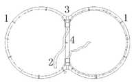
双圆盾构的同步注浆工艺(如图1所示)与传统的单圆盾构存在很大不同,同步注浆的不同主要表现在注浆管布置形式和浆液配比及相应物理特性的变化上。双圆盾构机普遍采用的是上、下海鸥块处的两点注浆形式,使用的是双液浆;而普通单圆盾构采用的是四点注浆形式,使用的是惰性浆。这一形式的变化导致了以下问题:注入的浆液不能够很好地填充盾构机周围的建筑空隙,尤其是在使用了缓凝或速凝的双浆液时;很难合理的分配上下两根注浆管的浆液量以确保地表沉陷的控制;也很难分开控制上下两管的注入压力和注入流量,以确保注入效果。双圆盾构在国内外使用的成功案例较少,其注浆系统还存在较多问题。The synchronous grouting process of the double-circle shield (as shown in Figure 1) is very different from the traditional single-circle shield. The difference in synchronous grouting is mainly reflected in the arrangement of the grouting pipes, the grout ratio and the corresponding physical properties. change. The double-circle shield machine generally adopts the two-point grouting form at the upper and lower seagull blocks, using double liquid slurry; while the ordinary single-circle shield adopts the four-point grouting form, using inert slurry. This change in form leads to the following problems: the injected grout cannot fill the construction voids around the shield machine well, especially when slow-setting or fast-setting double grout is used; it is difficult to reasonably distribute the upper and lower two grouts The amount of grout in the grouting pipe is to ensure the control of surface subsidence; it is also difficult to separately control the injection pressure and injection flow rate of the upper and lower pipes to ensure the injection effect. There are few successful cases of double-circle shield used at home and abroad, and there are still many problems in its grouting system.
发明内容Contents of the invention
本发明的目的是根据上述现有技术的不足之处,提供一种双圆盾构隧道多点管片壁后同步注浆方法,该方法针对不同的地层损失和盾构隧道的偏转程度,并根据现场的监控量测数据灵活选取管片的注浆孔对盾尾进行同步注浆,及时控制地层损失及盾构推进中产生的方向偏转,使地层损失及盾构隧道偏转始终与设计保持一致的一种盾构施工配套技术。The purpose of the present invention is to provide a method of synchronous grouting behind the multi-point segment wall of a double-circle shield tunnel according to the deficiencies of the above-mentioned prior art. The method is aimed at different formation losses and deflection degrees of the shield tunnel, and According to the on-site monitoring and measurement data, the grouting hole of the segment is flexibly selected to perform synchronous grouting on the tail of the shield, so as to timely control the formation loss and the direction deflection during the shield tunneling, so that the formation loss and the deflection of the shield tunnel are always consistent with the design A shield construction supporting technology.
本发明目的实现由以下技术方案完成:The object of the present invention is realized by the following technical solutions:
一种双圆盾构隧道多点壁后同步注浆方法,该方法涉及一种构成双圆盾构隧道的管片结构,所述管片结构的壁上开设有注浆孔,其内安装有全站仪,其特征在于该方法通过至少二个注浆孔进行同步注浆。A method for synchronous grouting behind the multi-point wall of a double-circle shield tunnel, the method relates to a segment structure constituting a double-circle shield tunnel, the wall of the segment structure is provided with a grouting hole, and a The total station is characterized in that the method performs synchronous grouting through at least two grouting holes.
在同步注浆前,通过全站仪测定管片结构的偏转值。Before synchronous grouting, the deflection value of the segment structure is measured by a total station.
同步注浆的具体方式是:在管片结构无偏转时,选择管片结构双肩处的二个注浆孔进行同步注浆,二个注浆孔的注浆量相同,注浆量为每孔2.5-4m3。The specific method of synchronous grouting is: when the segment structure has no deflection, select two grouting holes at both shoulders of the segment structure for synchronous grouting. 2.5-4m3.
同步注浆的具体方式是:在管片结构出现偏转时,选择高侧隧道顶部的注浆孔及低侧隧道底部的注浆孔进行同步注浆,管片结构高侧的注浆量大于管片结构低侧的注浆量,注浆量为每环6-8m3。The specific method of synchronous grouting is: when the segment structure deflects, select the grouting hole at the top of the high-side tunnel and the grouting hole at the bottom of the low-side tunnel for synchronous grouting. The amount of grouting on the lower side of the sheet structure, the amount of grouting is 6-8m3 per ring.
所述同步注浆完成后,选择盾尾后7-8环处管片结构低侧一底部注浆孔进行补偿注浆,所述底部吊装孔分为3-4次注入1.5-2m3浆液。After the synchronous grouting is completed, select a bottom grouting hole on the lower side of the segment structure at the 7-8th ring behind the shield tail for compensation grouting, and inject1.5-2m3 grout into the bottom hoisting hole in 3-4 times.
对于以上技术方案,具体解释如下:For the above technical solutions, the specific explanation is as follows:
上述出现的管片结构,在本技术方案中统指一环拼装管片。故上述中“在盾尾后4-5环处的管片结构中”,在此处应理解为选择盾尾后4-5环的一环管片结构。在本发明中其余位置出现的管片结构也均为此含义。The above-mentioned segment structures collectively refer to one-ring assembled segments in this technical solution. Therefore, "in the segment structure at the 4-5 rings behind the tail of the shield" mentioned above should be understood here as the selection of a segment structure of the 4-5 rings behind the tail of the shield. The segment structures appearing in other positions in the present invention also have this meaning.
上述出现的双肩处的二个注浆孔,具体指的是双圆隧道最高处的二个注浆孔。The two grouting holes at the shoulders mentioned above specifically refer to the two grouting holes at the highest point of the double-circular tunnel.
上述中对于出现偏转的管片结构,其中有“管片结构低侧底部和顶部的二注浆孔进行同步注浆”的描述,该技术方案是因为单从管片结构低侧底部注浆孔注浆,可能会因为注浆量大导致浆液流窜;及顶部注浆能有效控制地面沉降。故此在同步注浆进行监控,如需要时则在管片结构低侧顶部的注浆孔进行注浆。For the deflected segment structure mentioned above, there is a description of "synchronous grouting for the two grouting holes at the bottom and top of the segment structure". Grouting may cause the grout to flow due to the large amount of grouting; and top grouting can effectively control land subsidence. Therefore, monitoring is carried out during synchronous grouting, and if necessary, grouting is carried out at the grouting holes at the top of the lower side of the segment structure.
本发明的优点是:避免了地面沉降大及隧道偏转控制难的缺点,提高了双圆盾构隧道的施工质量,降低了双圆盾构机盾构操作人员的操作难度和施工风险,有利于现场施工管理。The invention has the advantages of avoiding the shortcomings of large ground subsidence and difficult tunnel deflection control, improving the construction quality of the double-circle shield tunnel, reducing the operation difficulty and construction risk of the shield operator of the double-circle shield machine, and being beneficial On-site construction management.
附图说明Description of drawings
附图1是现有双圆盾构同步注浆示意图;Accompanying
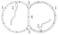
附图2是本发明实施例双圆盾构无偏转下同步注浆示意图;Accompanying
附图3是本发明实施例双圆盾构隧道注浆纠偏示意图。Accompanying
具体实施方式Detailed ways
以下结合附图通过实施例对本发明特征及其它相关特征作进一步详细说明,以便于同行业技术人员的理解:The features of the present invention and other related features will be further described in detail below in conjunction with the accompanying drawings through embodiments, so as to facilitate the understanding of those skilled in the art:
如图3所示,标号1-4分别表示:管片结构1、双液浆泵2、注浆孔3、中心立柱4。As shown in FIG. 3 , the numbers 1-4 respectively represent:
如图3所示,本发明施工流程如下:As shown in Figure 3, the construction process of the present invention is as follows:
1)建立盾构施工变形的人工神经网络预测与模糊逻辑控制模型及算法与要填充的盾尾建筑空隙体积,由已知当前时刻地表(地层)变形量及变化量反求下一时刻的施工可控参数的变化量(控制量),用以确定同步注浆量。同时在隧道内安装在具有遥控全自动功能的全站仪,以自动测定拼装完的管片结构1姿态。1) Establish the artificial neural network prediction and fuzzy logic control model and algorithm for shield construction deformation and the volume of the shield tail building void to be filled, and calculate the construction at the next moment from the known deformation and change of the ground surface (stratum) at the current moment The change amount (control amount) of the controllable parameter is used to determine the synchronous grouting amount. At the same time, a total station with remote control and automatic function is installed in the tunnel to automatically measure the posture of the assembled
2)根据上述所得的数据,由原有的管片结构1中上、下海鸥块处的两点注浆形式,改变为通过管片结构1中左、右隧道顶部注浆孔及其它注浆孔位置的注浆形式,调整后浆液易于均匀流动分配填充盾尾间隙,其具体施工方式如下:2) According to the data obtained above, the original two-point grouting at the upper and lower seagull blocks in the
对盾尾管片结构1的姿态进行实时监测,如果管片结构1未发生旋转,通过管片结构1双肩处的二个注浆孔进行同步注浆。The attitude of the shield
如管片结构1发生偏转,则在同步注浆时进行反压浆进行纠正,选择管片结构1高侧隧道顶部的注浆孔注浆,同时管片结构1低侧隧道底部的注浆孔进行同步注浆。具体的说既是:如盾构向右旋转,就需将注浆孔设在左上和右下,反之则应是右上和左下,见下图3。但是低侧隧道通过底部注浆,有可能出现双液浆流窜的情况,导致低侧隧道的上部出现空隙。在通过监测发现此类情况时,应及时浆液质量,确保浆液初凝时间。If the
对于上述双圆隧道旋转的纠正,还可采取低侧隧道底部补浆等措施,根据偏转情况,在盾尾后7~8环加注1.5-2m3浆,分3-4次注入。For the correction of the rotation of the above-mentioned double-circular tunnel, measures such as grout replenishment at the bottom of the low-side tunnel can also be taken. According to the deflection situation, 1.5-2m3 slurry is injected in the 7th to 8th rings behind the tail of the shield, and the injection is divided into 3-4 times.
结合上述施工流程,以下对于施工要求和材料选取进行详细说明。Combined with the above construction process, the construction requirements and material selection are described in detail below.
根据工程地质,采用自动的双液注浆工艺,主要根据设定土压力和推进速度进行控制。压送浆液采用变频调速双螺杆泵,A、B液分别输送。注浆浆液为凝胶时间可调的快凝复合注浆材料(主要由水泥、膨润土、水玻璃组成)。注浆配比(1m3)∶水泥∶350kg,膨润土∶50kg,粉煤灰100kg,水玻璃80l,水785l。According to the engineering geology, an automatic two-liquid grouting process is adopted, which is mainly controlled according to the set earth pressure and advancing speed. The pressure-feeding slurry adopts frequency conversion and speed-regulating twin-screw pump, and the A and B liquids are transported separately. The grouting slurry is a fast-setting composite grouting material (mainly composed of cement, bentonite, and water glass) with adjustable gel time. Grouting ratio (1m3 ): cement: 350kg, bentonite: 50kg, fly ash 100kg, water glass 80l, water 785l.
注浆设备由2台双液浆泵(1台备用)、搅拌机3台(1台备用)、2台水泵、2台泥浆泵、1台空压机和双液注浆管路系统等组成。注浆量根据环形间隙的理论容积,并取30-50%的损耗系数计算。注浆泵站设在盾构机的后续台车上,注浆材料由人工或隧道内电机车搬运到泵站。施工时应有专人密切注意返浆和压力突升等异常情况,尽量避免浆液流失。The grouting equipment consists of 2 double-fluid slurry pumps (1 spare), 3 mixers (1 spare), 2 water pumps, 2 mud pumps, 1 air compressor and a double-liquid grouting pipeline system. The amount of grouting is calculated based on the theoretical volume of the annular gap and a loss coefficient of 30-50%. The grouting pumping station is set on the subsequent trolley of the shield machine, and the grouting material is transported to the pumping station manually or by an electric locomotive in the tunnel. Special personnel should pay close attention to abnormal conditions such as slurry return and sudden pressure rise during construction, and try to avoid slurry loss.
注浆压力取决于地层的地质情况和地下水压力,注浆压力和注浆量的控制以确保填满全部建筑空隙。注浆作业操作的熟练取决于丰富的经验,过高的压力将导致浆液从盾尾窜入,影响盾构机的正常掘进。注浆顺序应先下部后上部。The grouting pressure depends on the geological conditions of the formation and the groundwater pressure. The control of the grouting pressure and the amount of grouting is to ensure that all the building voids are filled. The proficiency of grouting operations depends on rich experience. Excessive pressure will cause grout to rush in from the tail of the shield, affecting the normal excavation of the shield machine. The order of grouting should be lower first and then upper.
在施工前,将制作浆液试块,并对浆液的性能指标进行测试,性能指标包括稠度、初凝值、泌水率、抗压强度、比重。Before construction, the grout test block will be made, and the performance indexes of the grout will be tested, including consistency, initial setting value, bleeding rate, compressive strength, and specific gravity.
在施工过程中,对浆液取样测试,并根据实际注浆效果,对浆液配比进行调整优化,确保浆液质量。注浆压力≤0.3MPa,注浆量每孔2.5~4m3,每环6-8m3左右。During the construction process, the grout was sampled and tested, and the grout ratio was adjusted and optimized according to the actual grouting effect to ensure the quality of the grout. The grouting pressure is ≤0.3MPa, the grouting volume is 2.5~4m3 per hole, and about 6-8m3 per ring.
在纠偏转过程中,为了防止浆液流窜,初凝时间控制在8s以内,隧道较高一侧的注浆量略大于低的一侧;高的一侧利用浆液和注浆压力将隧道往下压,低的一侧托住隧道。In the deflection correction process, in order to prevent the grout from flowing, the initial setting time is controlled within 8s, and the grouting volume on the higher side of the tunnel is slightly larger than that on the lower side; the higher side uses the grout and grouting pressure to push the tunnel down , the lower side holds the tunnel.
通过对隧道管片背后外周多点同步适量地注浆,可以及时地充填地层与衬砌背后的环形建筑空隙,使隧道管片和周围土层形成一个整体结构,把盾构掘进造成的地层土量损失和扰动所引起的地表沉降尽可能地减小。根据上海地铁工程的施工技术和经验,能有效地把地表、地下管线及地面建构筑物的沉降量控制在规范以内。By synchronously injecting appropriate amount of grouting at multiple points around the back of the tunnel segment, the annular building gap behind the stratum and the lining can be filled in time, so that the tunnel segment and the surrounding soil form an integral structure, and the amount of stratum soil caused by shield excavation can be reduced. Surface subsidence caused by losses and disturbances shall be minimized as much as possible. According to the construction technology and experience of the Shanghai subway project, the settlement of the surface, underground pipelines and ground structures can be effectively controlled within the specification.
Claims (5)
Translated fromChinesePriority Applications (1)
| Application Number | Priority Date | Filing Date | Title |
|---|---|---|---|
| CN 200910308622CN101672185B (en) | 2009-10-22 | 2009-10-22 | Multi-point back synchronous injection method of double circular shield tunnel |
Applications Claiming Priority (1)
| Application Number | Priority Date | Filing Date | Title |
|---|---|---|---|
| CN 200910308622CN101672185B (en) | 2009-10-22 | 2009-10-22 | Multi-point back synchronous injection method of double circular shield tunnel |
Publications (2)
| Publication Number | Publication Date |
|---|---|
| CN101672185A CN101672185A (en) | 2010-03-17 |
| CN101672185Btrue CN101672185B (en) | 2011-11-02 |
Family
ID=42019565
Family Applications (1)
| Application Number | Title | Priority Date | Filing Date |
|---|---|---|---|
| CN 200910308622ActiveCN101672185B (en) | 2009-10-22 | 2009-10-22 | Multi-point back synchronous injection method of double circular shield tunnel |
Country Status (1)
| Country | Link |
|---|---|
| CN (1) | CN101672185B (en) |
Families Citing this family (13)
| Publication number | Priority date | Publication date | Assignee | Title |
|---|---|---|---|---|
| CN102434172A (en)* | 2011-12-14 | 2012-05-02 | 中国矿业大学 | Roadway surrounding rock stability control method for backfill grouting |
| CN103123252B (en)* | 2012-02-10 | 2015-08-05 | 南京大学 | Duct pieces of shield tunnel back synchronous injection many reference amounts real-time monitoring system |
| CN103742162B (en)* | 2014-01-20 | 2016-06-29 | 中铁工程装备集团有限公司 | Shield tail top is provided with shield machine and the synchronous grouting device of synchronous grouting device |
| CN105525928B (en)* | 2014-09-30 | 2019-12-10 | 中国铁建大桥工程局集团有限公司 | Construction method of shield inclined shaft segment wall rear plugging ring |
| CN104612724A (en)* | 2015-01-09 | 2015-05-13 | 同济大学 | Splicing structure for pipe pieces of ellipse-like shield tunnel with stand column |
| CN105257303A (en)* | 2015-10-28 | 2016-01-20 | 广州广隧机电设备有限公司 | Construction method capable of achieving synchronous double-grout grouting during shield tunneling |
| CN106089213B (en)* | 2016-05-06 | 2018-05-08 | 同济大学 | Shield tunnel simultaneous grouting slurry measured performance parameter system and method |
| CN106321117B (en)* | 2016-10-13 | 2018-09-21 | 北京航空航天大学 | A kind of cement mortar intelligent multipoint perfusion system |
| CN109340454B (en)* | 2018-09-27 | 2020-09-04 | 上海公路桥梁(集团)有限公司 | Correction method of reinforced concrete pipe jacking |
| CN110566233B (en)* | 2019-09-20 | 2021-04-09 | 成龙建设集团有限公司 | Method for duct piece wall post-grouting in shield tunnel construction of full-section hard rock stratum |
| CN112145189A (en)* | 2020-10-24 | 2020-12-29 | 中铁一局集团有限公司 | Novel duct piece grouting reinforcement method for soft soil area |
| CN112855182A (en)* | 2021-01-19 | 2021-05-28 | 吉力此且 | Duct piece back gap filling system device for shield and method thereof |
| CN113217037B (en)* | 2021-06-25 | 2022-08-30 | 中铁二局集团有限公司 | Backfill system and backfill method for single shield TBM or behind shield segment wall |
Citations (5)
| Publication number | Priority date | Publication date | Assignee | Title |
|---|---|---|---|---|
| JPH10252396A (en) | 1997-03-12 | 1998-09-22 | Taisei Corp | Structure of shield tunnel |
| JP2001329798A (en)* | 2000-05-19 | 2001-11-30 | Nippon Steel Corp | Segment assembly method |
| JP2004019351A (en)* | 2002-06-19 | 2004-01-22 | Taisei Corp | Double tunnel method, joint segment and assembly equipment |
| CN1821546A (en)* | 2006-03-31 | 2006-08-23 | 上海隧道工程股份有限公司 | Pipe blade assembling machine for rectangular shield |
| CN101457649A (en)* | 2009-01-04 | 2009-06-17 | 上海大学 | Double upright post lining structure of double-circle shield-tunneling-method tunnel |
- 2009
- 2009-10-22CNCN 200910308622patent/CN101672185B/enactiveActive
Patent Citations (5)
| Publication number | Priority date | Publication date | Assignee | Title |
|---|---|---|---|---|
| JPH10252396A (en) | 1997-03-12 | 1998-09-22 | Taisei Corp | Structure of shield tunnel |
| JP2001329798A (en)* | 2000-05-19 | 2001-11-30 | Nippon Steel Corp | Segment assembly method |
| JP2004019351A (en)* | 2002-06-19 | 2004-01-22 | Taisei Corp | Double tunnel method, joint segment and assembly equipment |
| CN1821546A (en)* | 2006-03-31 | 2006-08-23 | 上海隧道工程股份有限公司 | Pipe blade assembling machine for rectangular shield |
| CN101457649A (en)* | 2009-01-04 | 2009-06-17 | 上海大学 | Double upright post lining structure of double-circle shield-tunneling-method tunnel |
Also Published As
| Publication number | Publication date |
|---|---|
| CN101672185A (en) | 2010-03-17 |
Similar Documents
| Publication | Publication Date | Title |
|---|---|---|
| CN101672185B (en) | Multi-point back synchronous injection method of double circular shield tunnel | |
| CN104594911B (en) | Shield launching stage or reception stage wear down the construction method of operating line | |
| CN100580221C (en) | Construction method of shield tunnel passing through shallow soil-covered river bed | |
| WO2021189813A1 (en) | Construction method for crossing over existing line and crossing under sewage jacking pipe by means of water-rich sand layer shield tunneling machine at short distance | |
| CN108625866B (en) | Shield machine based on steel bushing device crosses ventilating shaft method | |
| CN110924962A (en) | Construction method for filling and grouting behind segment wall of EPB-TBM dual-mode shield | |
| CN114183152B (en) | A control method for shield attitude in small-radius multi-curve subway shield construction | |
| CN107842374B (en) | The novel inert slurry of shield and combination grouting process for upper soft lower hard water rich strata | |
| CN110924967B (en) | Fine control construction method for shield proximity sensitive building in water-rich sandy gravel stratum | |
| CN103603670A (en) | Construction method of ultra-deep-earthed shield crossing complex formations | |
| CN110735653A (en) | A deep hole retreat grouting water plugging construction method for igneous rock water-rich faults | |
| CN1215276C (en) | Earth pressure balancing technology for laying rectangular top pipe | |
| CN108049878A (en) | A kind of powder land floor shield cuts the construction method that stake is crossed the river | |
| CN104265307A (en) | Non-uniform-hardness stratum earth pressure balance shield tunnel underpassing railway existing line construction method | |
| CN208965598U (en) | The Anti-seeping technology structure of grout curtain and underground chamber intersection area | |
| CN104343455A (en) | Long-distance curved jacking pipe and pipe roof construction technique | |
| CN112482415B (en) | Consolidation grouting method for underground cavern under high external water pressure and flowing water condition | |
| CN111706337B (en) | Construction method for shield to penetrate high-speed rail | |
| CN109681236A (en) | Big cross section water-rich sand layer shield driving synchronous grouting method | |
| CN103510964A (en) | Method for performing backfill grouting on pea gravel by adoption of shield type TBM in construction process | |
| CN102400694A (en) | Method for reinforcing joint of shield tunnel and mine tunnel | |
| CN106122589A (en) | A kind of earth pressure balance method | |
| CN101793154A (en) | Method for grouting for stopping up water by using geological parameters of tunnel surrounding rocks and setting relief holes | |
| CN104790419A (en) | Dewatering construction method applicable to tunnel in water-rich quicksand stratum | |
| CN104533432A (en) | Construction method for shield to penetrate through buildings in old town of downtown in complex stratums |
Legal Events
| Date | Code | Title | Description |
|---|---|---|---|
| C06 | Publication | ||
| PB01 | Publication | ||
| C10 | Entry into substantive examination | ||
| SE01 | Entry into force of request for substantive examination | ||
| C14 | Grant of patent or utility model | ||
| GR01 | Patent grant | ||
| C56 | Change in the name or address of the patentee | Owner name:SHANGHAI URBAN CONSTRUCTION MUNICIPAL ENGINEERING Free format text:FORMER NAME: SHANGHAI NO.2 MUNICIPAL ENGINEERING CO., LTD. | |
| CP01 | Change in the name or title of a patent holder | Address after:200232 Xuhui District, Liuzhou Wu Road, Lane No. 13, No. 3, No. Patentee after:Shanghai urban construction Municipal Engineering (Group) Co., Ltd. Address before:200232 Xuhui District, Liuzhou Wu Road, Lane No. 13, No. 3, No. Patentee before:Shanghai No.2 Municipal Engineering Co., Ltd. |