CN101666745B - Laser-induced spectrum measurement device with self-adjusting calibration function and control method - Google Patents
Laser-induced spectrum measurement device with self-adjusting calibration function and control methodDownload PDFInfo
- Publication number
- CN101666745B CN101666745BCN2009100755763ACN200910075576ACN101666745BCN 101666745 BCN101666745 BCN 101666745BCN 2009100755763 ACN2009100755763 ACN 2009100755763ACN 200910075576 ACN200910075576 ACN 200910075576ACN 101666745 BCN101666745 BCN 101666745B
- Authority
- CN
- China
- Prior art keywords
- light source
- frequency band
- lens
- optical fiber
- computer
- Prior art date
- Legal status (The legal status is an assumption and is not a legal conclusion. Google has not performed a legal analysis and makes no representation as to the accuracy of the status listed.)
- Expired - Fee Related
Links
Images


Landscapes
- Investigating, Analyzing Materials By Fluorescence Or Luminescence (AREA)
Abstract
Translated fromChinese
Description
Translated fromChinese技术领域technical field
本发明涉及激光感生光谱测量技术,具体是一种具有自调整校准功能的激光感生光谱测量装置及控制方法。The invention relates to laser-induced spectrum measurement technology, in particular to a laser-induced spectrum measurement device and a control method with self-adjusting and calibrating functions.
背景技术Background technique
激光感生光谱(Laser Induced Breakdown Spectroscopy,LIBS)是一种新型光谱分析技术,利用聚焦的强脉冲激光激发物质产生等离子体,通过分析等离子体中的原子或离子发光光谱获得物质元素成分含量信息,实现对样品的元素分析。LIBS技术具有样品制备简单、多元素同步分析、分析速度快等优点,因此该技术被广泛应用于各种物质的定性或定量分析,有着巨大的实用价值。目前,LIBS技术已经应用于环境污染监测、工业产品检测和考古分析等领域。Laser Induced Breakdown Spectroscopy (LIBS) is a new type of spectral analysis technology that uses focused intense pulsed lasers to excite matter to generate plasma, and obtains information on the content of material elements by analyzing the atomic or ion luminescence spectrum in the plasma. Realize the elemental analysis of the sample. LIBS technology has the advantages of simple sample preparation, multi-element simultaneous analysis, and fast analysis speed. Therefore, this technology is widely used in the qualitative or quantitative analysis of various substances and has great practical value. At present, LIBS technology has been applied in the fields of environmental pollution monitoring, industrial product detection and archaeological analysis.
在采用激光感生光谱技术进行物质元素成分分析时,需要将激光聚焦在被分析物质表面下某一负离焦量处,即激光聚焦点的位置要控制在被分析物质表面下、满足测量要求的距离范围内,此外,入射激光的离焦量变化对等离子体的形成影响较大,决定了等离子体产生的效率和效果,而且准确控制激光的聚焦点位置可以提高激发的功率密度,在相同功率密度的情况下则可降低脉冲激光源的功率;另外,需要将光纤探头对准激光激发出来的等离子体,才能高效、有效采集脉冲激光激发产生的等离子体发出的特征光谱,减少杂散光和背景光的影响,最大限度的提高所采集特征光谱的强度,才能提高分析的精度。When using laser-induced spectroscopy to analyze the composition of material elements, it is necessary to focus the laser on a certain negative defocus under the surface of the analyzed material, that is, the position of the laser focus point must be controlled under the surface of the analyzed material to meet the measurement requirements. In addition, the change of the defocus amount of the incident laser has a great influence on the formation of plasma, which determines the efficiency and effect of plasma generation, and accurately controlling the laser focus position can increase the excitation power density. In the case of low power density, the power of the pulsed laser source can be reduced; in addition, the optical fiber probe needs to be aligned with the plasma excited by the laser in order to efficiently and effectively collect the characteristic spectrum emitted by the plasma generated by the pulsed laser excitation, reducing stray light and In order to improve the accuracy of the analysis, the influence of background light should be maximized to increase the intensity of the collected characteristic spectrum.
因此,激光聚焦点位置的控制与光纤探头的对准控制是激光感生光谱技术的两大重点。而现有激光感生光谱测量装置中都难以保证激光聚焦点位置的精确控制和光纤探头的准确对准,本领域的技术人员总要在设备和试验装置的调试中做很多工作,经过反复调整才能获得一个较为理想的设备状态,但是该状态却不能保证其最优性和多次调整的重复性。这是因为在现有激光感生光谱测量装置的调整方法中,激光聚焦点位置的调整是依靠量具测量和人眼观察等离子体发光点来确定的,由于不同人的视差存在差异,必然导致调整的不一致性,而且当样品表面不平整和不规则时,调整的难度和不确定性还会进一步增大。Therefore, the control of the laser focal point position and the alignment control of the fiber optic probe are the two key points of the laser-induced spectroscopy technology. However, in the existing laser-induced spectroscopy measurement devices, it is difficult to ensure the precise control of the laser focus point position and the accurate alignment of the optical fiber probe. Only in this way can an ideal equipment state be obtained, but this state cannot guarantee its optimality and repeatability of multiple adjustments. This is because in the existing adjustment method of the laser-induced spectrum measurement device, the adjustment of the laser focal point position is determined by measuring the measuring tool and observing the plasma luminous point by the human eye. Due to the difference in the parallax of different people, it will inevitably lead to adjustment Inconsistency, and when the sample surface is uneven and irregular, the difficulty and uncertainty of adjustment will further increase.
光纤探头的对准调整除依靠人眼观察外,主要通过观察激光激发物质产生的等离子体在光谱仪中的谱线强弱来实现。但是由于如下原因使得光纤探头对准难度过大,不易实现光纤探头准确对准:1、脉冲激光器激发能量不稳定(通常脉冲激光器激发能量的稳定度在±3%),两次激发后,光谱仪采集的数据存在较大波动;2、脉冲激光对物质激发后产生的光谱谱线较多,选择适合的波长谱线及稳定光强作为参照量存在难度;3、脉冲激光的不连续性。The alignment adjustment of the fiber optic probe is mainly realized by observing the spectral line intensity of the plasma generated by the laser-excited material in the spectrometer, in addition to relying on the observation of the human eye. However, due to the following reasons, it is too difficult to align the optical fiber probe, and it is difficult to achieve accurate alignment of the optical fiber probe: 1. The excitation energy of the pulsed laser is unstable (usually the stability of the excitation energy of the pulsed laser is ± 3%). After two excitations, the spectrometer There are large fluctuations in the collected data; 2. There are many spectral lines generated after the pulsed laser excites the substance, and it is difficult to select a suitable wavelength spectral line and stable light intensity as a reference quantity; 3. The discontinuity of the pulsed laser.
另外,考虑到激光感生光谱测量装置在实际应用中的具体情况。虽然激光感生光谱测量装置的各仪器大都有防震动措施和装置,但是难免因工作环境或其他意外因素使设备偏离最佳工作状态,在这种情况下如果没有有效的自调整和校准手段,将难以保证激光感生光谱测量装置正常稳定的工作。In addition, the specific situation of the laser-induced spectroscopy measurement device in practical applications is considered. Although most of the instruments of the laser-induced spectroscopy measurement device have anti-vibration measures and devices, it is inevitable that the equipment will deviate from the optimal working state due to the working environment or other accidental factors. In this case, if there is no effective self-adjustment and calibration means, It will be difficult to guarantee the normal and stable operation of the laser-induced spectroscopy measurement device.
发明内容Contents of the invention
本发明为了解决现有激光感生光谱测量装置实现激光聚焦点调整和光纤探头对准的调整方法存在难度大、无法保证调整效果的问题,提供了一种具有自调整校准功能的激光感生光谱测量装置及控制方法。In order to solve the problem that the existing laser-induced spectrum measurement device realizes the adjustment method of laser focus point adjustment and optical fiber probe alignment, which is difficult and cannot guarantee the adjustment effect, a laser-induced spectrum with self-adjusting and calibrating function is provided. Measuring device and control method.
本发明是采用如下技术方案实现的:具有自调整校准功能的激光感生光谱测量装置,包括待测物品放置平台、光谱采集分析组件;所述光谱采集分析组件包含光谱仪、受光谱仪控制的脉冲激光器、至少一个经传导光纤与光谱仪相应通道相连的光纤探头,待测物品放置平台置于脉冲激光器的正下方,脉冲激光器的光学窗口与待测物品放置平台正对设置,且脉冲激光器的光学窗口前设置有聚焦透镜;所述测量装置还包括计算机、辅助光源组件、以及计算机经由电控单元控制的对焦调整组件和光纤探头角度调整组件,光谱采集分析组件中的光谱仪与计算机相连;The present invention is realized by adopting the following technical solutions: a laser-induced spectral measuring device with self-adjusting and calibrating functions, including a platform for placing objects to be measured, and a spectrum acquisition and analysis component; the spectrum acquisition and analysis component includes a spectrometer and a pulsed laser controlled by the spectrometer , At least one optical fiber probe connected to the corresponding channel of the spectrometer through a conductive fiber, the platform for the object to be tested is placed directly below the pulse laser, the optical window of the pulse laser is set directly opposite to the platform for the object to be tested, and the optical window of the pulse laser is in front of A focusing lens is provided; the measuring device also includes a computer, an auxiliary light source assembly, a focus adjustment assembly and an optical fiber probe angle adjustment assembly controlled by the computer via an electronic control unit, and the spectrometer in the spectrum collection and analysis assembly is connected to the computer;
所述对焦调整组件包括光学放大透镜组、经光学放大透镜组与待测物品放置平台上与聚焦透镜正对区域正对的CCD图像传感器、以及设置于待测物品放置平台下的电动升降机构,CCD图像传感器经接口电路与计算机相连,电动升降机构与电控单元相连;The focus adjustment assembly includes an optical magnification lens group, a CCD image sensor that is directly opposite to the area where the focusing lens is placed on the object-to-be-tested placement platform through the optical magnification lens group, and an electric lifting mechanism arranged under the article-to-be-tested placement platform, The CCD image sensor is connected to the computer through the interface circuit, and the electric lifting mechanism is connected to the electronic control unit;
所述光纤探头角度调整组件由各光纤探头分别配设的电控旋转装置构成,各电控旋转装置与电控单元相连;The optical fiber probe angle adjustment assembly is composed of electronically controlled rotating devices respectively equipped with each optical fiber probe, and each electrically controlled rotating device is connected with an electronic control unit;
所述辅助光源组件包含与计算机相连的电控恒流源、以45°角倾斜设置于脉冲激光器与聚焦透镜之间的选择透反透镜、与光纤探头一一对应的频段校准光源,频段校准光源发出的光的波长在对应光纤探头的光谱测量范围内,各频段校准光源与选择透反透镜之间设置有使频段校准光源发出的光由选择透反透镜反射后平行入射聚焦透镜的光学镜片组件,或者频段校准光源发出的光直接经由选择透反透镜反射后平行入射聚焦透镜,各频段校准光源与电控恒流源相连。其中,脉冲激光器的光学窗口与聚焦透镜间的选择透反透镜是经过镀膜处理的镜片,用于透射脉冲激光器发出的脉冲激光,反射频段校准光源发出的校准辅助光。The auxiliary light source assembly includes an electronically controlled constant current source connected to the computer, a selective transflective lens arranged between the pulse laser and the focusing lens at an angle of 45°, a frequency band calibration light source corresponding to the fiber optic probe one by one, and the frequency band calibration light source The wavelength of the emitted light is within the spectral measurement range of the corresponding fiber optic probe. An optical lens assembly is arranged between the calibration light source of each frequency band and the selective transflective lens so that the light emitted by the frequency band calibration light source is reflected by the selective transflective lens and then parallel to the incident focusing lens. , or the light emitted by the frequency band calibration light source is directly reflected by the selective transflective lens and then parallel to the focusing lens, and each frequency band calibration light source is connected with an electronically controlled constant current source. Among them, the selective transflective lens between the optical window of the pulse laser and the focusing lens is a coated lens, which is used to transmit the pulse laser emitted by the pulse laser and reflect the calibration auxiliary light emitted by the calibration light source in the frequency band.
具有自调整校准功能的激光感生光谱测量装置的控制方法,包括对焦调整步骤和光纤探头角度调整步骤;A control method of a laser-induced spectrum measurement device with a self-adjusting calibration function, including a focus adjustment step and an optical fiber probe angle adjustment step;
所述对焦调整步骤包含如下步骤:The focus adjustment step includes the following steps:
a、将被分析物质放于待测物品放置平台上;a. Put the analyte on the platform where the item to be tested is placed;
b、由计算机控制电控恒流源打开任一频段校准光源,被打开频段校准光源发出恒定亮度的平行光,直接经由选择透反透镜反射后平行入射聚焦透镜,或者经由光学镜片组件入射选择透反透镜,经选择透反透镜反射后平行入射聚焦透镜,经聚焦透镜聚焦,在被分析物质表面形成光斑;b. The computer controls the electronically controlled constant current source to turn on any frequency band calibration light source, and the turned on frequency band calibration light source emits parallel light with constant brightness, which is directly reflected by the selective transflective lens and then parallel incident on the focusing lens, or incident on the selective transmissive lens through the optical lens assembly. The anti-lens, reflected by the selected transflective lens, is parallel to the incident focusing lens, and is focused by the focusing lens to form a light spot on the surface of the analyzed substance;
c、由计算机经接口电路控制CCD图像传感器实时采集光斑图像,并对光斑图像处理后,计算光斑核的有效面积;其中,CCD图像传感器前的光学放大透镜组实现光斑放大,便于光斑在CCD图像传感器上成像;c. The CCD image sensor is controlled by the computer through the interface circuit to collect the spot image in real time, and after the spot image is processed, the effective area of the spot nucleus is calculated; wherein, the optical magnification lens group in front of the CCD image sensor realizes the spot enlargement, which is convenient for the spot on the CCD image Imaging on the sensor;
d、计算机根据计算得到的光斑核有效面积数据,经电控单元控制待测物品放置平台下的电动升降机构动作,使电动升降机构带动待测物品放置平台向着光斑核有效面积减少的方向升降,直到光斑核有效面积减少到计算机内保存的预定阈值以下,则控制电动升降机构停动,完成测量装置对焦;d. According to the calculated effective area data of the spot nucleus, the computer controls the action of the electric lifting mechanism under the platform for the item to be tested through the electronic control unit, so that the electric lifting mechanism drives the platform for the article to be tested to move up and down in the direction of reducing the effective area of the spot nucleus. Until the effective area of the spot nucleus decreases below the predetermined threshold stored in the computer, the electric lifting mechanism is controlled to stop, and the focusing of the measuring device is completed;
所述光纤探头角度调整步骤包含如下步骤:The step of adjusting the angle of the optical fiber probe includes the following steps:
e、由计算机控制电控恒流源打开其中一频段校准光源,被打开频段校准光源发出恒定亮度的平行光,直接经由选择透反透镜反射后平行入射聚焦透镜,或者经由光学镜片组件入射选择透反透镜,经选择透反透镜反射后平行入射聚焦透镜,经聚焦透镜聚焦,在被分析物质表面形成光斑;e. The computer controls the electronically controlled constant current source to turn on one of the frequency band calibration light sources, and the turned on frequency band calibration light source emits parallel light with constant brightness, which is directly reflected by the selective transflective lens and then parallel incident on the focusing lens, or incident on the selective transmissive lens through the optical lens assembly. The anti-lens, reflected by the selected transflective lens, is parallel to the incident focusing lens, and is focused by the focusing lens to form a light spot on the surface of the analyzed substance;
f、由计算机确定光纤探头扫描范围、及扫描起始点,要保证光斑位于光纤探头扫描范围内,并启动光谱仪;f. The computer determines the scanning range of the fiber optic probe and the starting point of the scan. Ensure that the spot is within the scanning range of the fiber optic probe and start the spectrometer;
g、计算机经电控单元控制与被打开频段校准光源对应的光纤探头配置的电控旋转装置动作,使该电控旋转装置带动光纤探头由扫描起始点开始,在步骤f中确定的光纤探头扫描范围内逐行或逐列进行扫描,寻找光斑;同时,计算机经由光谱仪实时读取与被打开频段校准光源对应的光纤探头的实时扫描数据D(λi),计算与实时扫描数据D(λi)对应的平均值D,比较实时扫描数据D(λi)中与被打开频段校准光源发出光的波长对应的数据值与平均值D大小;g. The computer controls the action of the electronically controlled rotating device configured with the optical fiber probe corresponding to the opened frequency band calibration light source through the electronic control unit, so that the electronically controlled rotating device drives the optical fiber probe to start from the scanning starting point, and the optical fiber probe determined in step f scans Scan row by row or column by row within the range to find the spot; at the same time, the computer reads the real-time scanning data D(λi ) of the optical fiber probe corresponding to the opened frequency band calibration light source through the spectrometer in real time, and calculates and real-time scanning data D(λi ) corresponding to the average value D, compare the real-time scanning data D(λi ) with the data value corresponding to the wavelength of the light emitted by the opened frequency band calibration light source and the average value D;
h、当实时扫描数据D(λi)中与被打开频段校准光源发出光的波长对应的数据值明显大于实时扫描数据D(λi)的平均值D时,计算机采用爬山法控制与被打开频段校准光源对应的光纤探头配置的电控旋转装置动作,使该电控旋转装置带动光纤探头进行微步距扫描,直至在实时扫描数据D(λi)中获得与被打开频段校准光源发出光的波长对应的最大数据值,则控制与被打开频段校准光源对应的光纤探头配置的电控旋转装置停动,完成测量装置中与被打开频段校准光源对应的光纤探头对准调整;所述爬山法是数据搜索领域中的常用方法。h. When the real-time scan data D(λi ) corresponding to the wavelength of light emitted by the opened frequency band calibration light source is significantly greater than the average value D of the real-time scan data D(λi ), the computer adopts the hill-climbing method to control and be opened The electronically controlled rotating device of the optical fiber probe corresponding to the frequency band calibration light source moves, so that the electronically controlled rotating device drives the optical fiber probe to perform micro-step scanning until the real-time scanning data D(λi ) is obtained and the frequency band calibration light source is turned on. The maximum data value corresponding to the wavelength, then control the electronically controlled rotating device configured with the optical fiber probe corresponding to the opened frequency band calibration light source to stop, and complete the alignment adjustment of the optical fiber probe corresponding to the opened frequency band calibration light source in the measurement device; It is a common method in the field of data search.
其中,如实时扫描数据D(λi)中与被打开频段校准光源发出光的波长对应的数据值为光谱仪输出量程的最大值时,则说明光斑亮度太强导致光谱仪输入饱和,则由计算机控制电控恒流源降低被打开频段校准光源的发光强度,重复进行步骤g、h,直至完成测量装置中与被打开频段校准光源对应的光纤探头对准调整;Among them, if the data value corresponding to the wavelength of the light emitted by the opened frequency band calibration light source in the real-time scanning data D(λi ) is the maximum value of the output range of the spectrometer, it means that the brightness of the spot is too strong to cause the input saturation of the spectrometer, and then it is controlled by the computer The electronically controlled constant current source reduces the luminous intensity of the opened frequency band calibration light source, and repeats steps g and h until the alignment adjustment of the optical fiber probe corresponding to the opened frequency band calibration light source in the measuring device is completed;
i、重复进行步骤e至h,直至完成测量装置中所有光纤探头的对准调整。i. Repeat steps e to h until the alignment adjustment of all fiber optic probes in the measuring device is completed.
本发明所述测量装置在经过上述控制方法调整后,即可对放于待测物品放置平台上的被分析物质实施分析:光谱仪在计算机控制下,控制脉冲激光器发出脉冲激光,脉冲激光经选择透反透镜透射后,平行入射聚焦透镜,经聚焦透镜聚焦到被分析物质上,激发被分析物质产生等离子体,等离子体中原子或离子的发光光谱经由光纤探头采集,经传导光纤传输至光谱仪,由光谱仪进行分析。After being adjusted by the above control method, the measuring device of the present invention can analyze the analyte placed on the platform of the object to be measured: the spectrometer is controlled by the computer to control the pulse laser to emit pulse laser, and the pulse laser is selected through the After the anti-lens is transmitted, the parallel incident focusing lens is focused on the analyzed substance through the focusing lens, and the analyzed substance is excited to generate plasma. The luminescent spectrum of the atoms or ions in the plasma is collected by the optical fiber probe and transmitted to the spectrometer through the conducting optical fiber. spectrometer for analysis.
与现有技术相比,本发明增设辅助光源组件、对焦调整组件和光纤探头角度调整组件,直接对被分析物质进行激光聚焦点位置调整和光纤探头对准,由辅助光源组件为对焦调整组件和光纤探头角度调整组件提供连续光源,使得激光感生光谱测量装置中激光聚焦点位置的控制与光纤探头的对准控制有了切实可靠的依据,摆脱了人为观察调整带来的不确定性;对焦调整组件以CCD图像传感器采集由辅助光源组件在待测物品放置平台上被分析物质表面形成的光斑图像,将光斑图像提供给计算机分析,由计算机控制电动升降机构,改变待测物品放置平台高度,高精度完成本发明所述测量装置的对焦调整,提高激光激发等离子体时的功率密度,提高等离子体产生的效率和效果;光纤探头角度调整组件以电控旋转装置控制光纤探头对被分析物质表面进行扫描,捕捉由辅助光源组件在待测物品放置平台上被分析物质表面形成的光斑图像核心,使光纤探头高精度对准激光聚焦点位置,从而使得光谱仪通过光纤探头能高效、有效采集脉冲激光激发产生的等离子体发出的特征光谱,提高光谱仪对被分析物质的分析精度。且本发明所述测量装置的控制方法以全自动化方式实现,自动化程度高,使得本发明所述测量装置可以在无需人为干预的情况下连续进行测量,提高了测量装置的适用性和测量效率。Compared with the prior art, the present invention adds an auxiliary light source assembly, a focus adjustment assembly and an optical fiber probe angle adjustment assembly to directly adjust the position of the laser focus point and align the optical fiber probe to the analyte. The auxiliary light source assembly is the focus adjustment assembly and the optical fiber probe. The optical fiber probe angle adjustment component provides a continuous light source, which makes the control of the laser focus point position and the alignment control of the optical fiber probe in the laser-induced spectroscopy measurement device a reliable basis, and gets rid of the uncertainty caused by manual observation and adjustment; The adjustment component uses the CCD image sensor to collect the light spot image formed by the auxiliary light source component on the surface of the analyzed substance on the object-to-be-tested platform, and provides the light spot image to the computer for analysis. The computer controls the electric lifting mechanism to change the height of the object-to-be-tested platform. The focus adjustment of the measuring device described in the present invention is completed with high precision, the power density when the laser excites the plasma is improved, and the efficiency and effect of plasma generation are improved; Scanning to capture the core of the spot image formed by the auxiliary light source component on the surface of the analyzed substance on the platform to be tested, so that the fiber optic probe can be aligned with the laser focus point with high precision, so that the spectrometer can efficiently and effectively collect pulsed laser light through the fiber optic probe The characteristic spectrum emitted by the excited plasma improves the analysis accuracy of the spectrometer for the analyzed substance. Moreover, the control method of the measuring device of the present invention is realized in a fully automated manner with a high degree of automation, so that the measuring device of the present invention can continuously perform measurements without human intervention, improving the applicability and measuring efficiency of the measuring device.
本发明所述测量装置结构简单,使用效果好,控制方法简单、合理,高精度实现激光聚焦点调整和光纤探头对准。The measuring device of the invention has the advantages of simple structure, good use effect, simple and reasonable control method, and high-precision adjustment of the laser focus point and alignment of the optical fiber probe.
附图说明Description of drawings
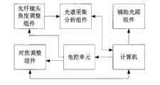
图1为本发明所述测量装置的结构方框图;Fig. 1 is the structural block diagram of measuring device of the present invention;
图2为本发明所述测量装置的一种结构示意图;Fig. 2 is a kind of structural representation of measuring device of the present invention;
图3为本发明所述测量装置的另一种结构示意图;Fig. 3 is another kind of structural representation of measuring device of the present invention;
图4为本发明所述测量装置的第三种结构示意图;Fig. 4 is the 3rd kind of structural representation of measuring device of the present invention;
图5为光纤探头扫描范围及扫描起始点的示意图;Fig. 5 is a schematic diagram of the scanning range of the fiber optic probe and the scanning starting point;
图6为CCD图像传感器采集到的光斑图像;Fig. 6 is the light spot image collected by CCD image sensor;
图7为图6中光斑图像经处理后的光斑核图像;Fig. 7 is the speckle kernel image after the spot image in Fig. 6 is processed;
图中:1-待测物品放置平台;2-光谱仪;3-脉冲激光器;4、5、6-传导光纤;7、8、9-光纤探头;10-聚焦透镜;11-计算机;12-光学放大透镜组;13-CCD图像传感器;14-电动升降机构;15-接口电路;16、17、18-电控旋转装置;19-电控恒流源;20-选择透反透镜;21、22、23-频段校准光源;24-光学镜片组件;25-反射镜;26、27-选择透反透镜;28-反射镜;29-被分析物质;30-光斑;31-光纤探头扫描范围;32-扫描起始点;33-电控单元。In the figure: 1-the platform for the object to be tested; 2-spectrometer; 3-pulse laser; 4, 5, 6-conducting optical fiber; 7, 8, 9-fiber probe; 10-focusing lens; 11-computer; 12-optics Magnifying lens group; 13-CCD image sensor; 14-electric lifting mechanism; 15-interface circuit; 16, 17, 18-electrically controlled rotating device; 19-electrically controlled constant current source; 20-select transflective lens; 21, 22 , 23-frequency band calibration light source; 24-optical lens assembly; 25-mirror; 26, 27-selective transflective lens; 28-mirror; - scanning starting point; 33 - electronic control unit.
具体实施方式Detailed ways
具有自调整校准功能的激光感生光谱测量装置,包括待测物品放置平台1、光谱采集分析组件;所述光谱采集分析组件包含光谱仪2、受光谱仪2控制的脉冲激光器3、至少一个经传导光纤4与光谱仪2相应通道相连的光纤探头7,待测物品放置平台1置于脉冲激光器3的正下方,脉冲激光器3的光学窗口与待测物品放置平台1正对设置,且脉冲激光器3的光学窗口前设置有聚焦透镜10;所述测量装置还包括计算机11、辅助光源组件、以及计算机11经由电控单元33控制的对焦调整组件和光纤探头角度调整组件,光谱采集分析组件中的光谱仪2与计算机11相连,如图1所示;A laser-induced spectral measuring device with a self-adjusting and calibrating function, comprising a
所述对焦调整组件包括光学放大透镜组12、经光学放大透镜组12与待测物品放置平台1上与聚焦透镜10正对区域正对的CCD图像传感器13、以及设置于待测物品放置平台1下的电动升降机构14,CCD图像传感器13经接口电路15与计算机11相连,电动升降机构14与电控单元33相连;The focus adjustment assembly includes an optical
所述光纤探头角度调整组件由各光纤探头7分别配设的电控旋转装置16构成,各电控旋转装置16与电控单元33相连;The optical fiber probe angle adjustment assembly is composed of an electronically controlled rotating
所述辅助光源组件包含与计算机11相连的电控恒流源19、以45°角倾斜设置于脉冲激光器3与聚焦透镜10之间的选择透反透镜20、与光纤探头7一一对应的频段校准光源21,频段校准光源21发出的光的波长在对应光纤探头7的光谱测量范围内,各频段校准光源21与选择透反透镜20之间设置有使频段校准光源21发出的光由选择透反透镜20反射后平行入射聚焦透镜10的光学镜片组件24,或者频段校准光源21发出的光直接经由选择透反透镜20反射后平行入射聚焦透镜10,各频段校准光源21与电控恒流源19相连。The auxiliary light source assembly includes an electronically controlled constant
具体实施时,如图4所示,频段校准光源21发出的光直接经由选择透反透镜20反射后平行入射聚焦透镜10,由于脉冲激光器3的光学窗口与聚焦透镜10间的距离有限,不便过多设置选择透反透镜20,因此,图4所示结构适用于仅设置单一光纤探头7的、应用单通道光谱仪实现单一频段范围光谱测量分析的测量装置;如图2、3所示,设置于各频段校准光源7与选择透反透镜20之间使频段校准光源7发出的光由选择透反透镜20反射后平行入射聚焦透镜10的光学镜片组件24至少可以按图2、3中公开的结构实现,光传导过程列举如下:如图2所示,其中一频段校准光源21发出的光经由反射镜25反射后,依次透射选择透反透镜26、27,再经由反射镜28反射后,入射选择透反透镜20,由选择透反透镜20反射后平行入射聚焦透镜10;如图3所示,其中一频段校准光源22发出的光经由选择透反透镜26反射后,透射选择透反透镜27,入射选择透反透镜20,由选择透反透镜20反射后平行入射聚焦透镜10。且光学镜片组件24亦应用了选择透反透镜26、27,用于反射与选择透反透镜对应的频段校准光源发出的光,透射其它频段校准光源发出的光。During specific implementation, as shown in Figure 4, the light emitted by the frequency band calibration light source 21 is directly reflected by the selective transflective lens 20 and then parallel incident on the focusing lens 10, because the distance between the optical window of the pulse laser 3 and the focusing lens 10 is limited, it is inconvenient Multiple settings select the transflective lens 20, therefore, the structure shown in Figure 4 is applicable to a measuring device that only has a single optical fiber probe 7, and uses a single-channel spectrometer to achieve spectral measurement and analysis of a single frequency range; as shown in Figures 2 and 3, it is set in Between each frequency band calibration light source 7 and the selective transflective lens 20, the light emitted by the frequency band calibration light source 7 is reflected by the selective transflective lens 20, and the optical lens assembly 24 of the parallel incident focusing lens 10 can be at least according to the structure disclosed in FIGS. 2 and 3 Realization, the light transmission process is listed as follows: As shown in Figure 2, the light emitted by one of the frequency band calibration light sources 21 is reflected by the reflector 25, and then transmitted through the selected transflective lenses 26 and 27 in turn, and then reflected by the reflector 28, the incident selected The transflective lens 20 is reflected by the selected transflective lens 20 and is parallel to the incident focusing lens 10; It is incident on the selective transflective lens 20 , is reflected by the selective transflective lens 20 , and then enters the focusing lens 10 in parallel. Moreover, the
具有自调整校准功能的激光感生光谱测量装置的控制方法,包括对焦调整步骤和光纤探头角度调整步骤;A control method of a laser-induced spectrum measurement device with a self-adjusting calibration function, including a focus adjustment step and an optical fiber probe angle adjustment step;
所述对焦调整步骤包含如下步骤:The focus adjustment step includes the following steps:
a、将被分析物质29放于待测物品放置平台1上;a. Put the
b、由计算机11控制电控恒流源19打开任一频段校准光源21,被打开频段校准光源21发出恒定亮度的平行光,直接经由选择透反透镜20反射后平行入射聚焦透镜10,或者经由光学镜片组件24入射选择透反透镜20,经选择透反透镜20反射后平行入射聚焦透镜10,经聚焦透镜10聚焦,在被分析物质29表面形成光斑30;b. The
c、由计算机11经接口电路15控制CCD图像传感器13实时采集光斑图像(如图6所示),并对光斑图像处理后(如图7所示),计算光斑核的有效面积;其中,CCD图像传感器13前的光学放大透镜组12实现光斑30放大,便于光斑30在CCD图像传感器13上成像;C, control
d、计算机11根据计算得到的光斑核有效面积数据,经电控单元33控制待测物品放置平台1下的电动升降机构14动作,使电动升降机构14带动待测物品放置平台1向着光斑核有效面积减少的方向升降,直到光斑核有效面积减少到计算机11内保存的预定阈值以下,则控制电动升降机构14停动,完成测量装置对焦;d. The
所述光纤探头角度调整步骤包含如下步骤:The step of adjusting the angle of the optical fiber probe includes the following steps:
e、由计算机11控制电控恒流源19打开其中一频段校准光源21,被打开频段校准光源21发出恒定亮度的平行光,直接经由选择透反透镜20反射后平行入射聚焦透镜10,或者经由光学镜片组件24入射选择透反透镜20,经选择透反透镜20反射后平行入射聚焦透镜10,经聚焦透镜10聚焦,在被分析物质29表面形成光斑30;e. The
f、如图5所示,由计算机11确定光纤探头扫描范围31、及扫描起始点32,要保证光斑30位于光纤探头扫描范围31内,并启动光谱仪2;f, as shown in Figure 5, the
g、计算机11经电控单元33控制与被打开频段校准光源21对应的光纤探头7配置的电控旋转装置16动作,使该电控旋转装置16带动光纤探头7由扫描起始点32开始,在步骤f中确定的光纤探头扫描范围31内逐行或逐列进行扫描,寻找光斑30;同时,计算机11经由光谱仪2实时读取与被打开频段校准光源16对应的光纤探头7的实时扫描数据D(λi),计算与实时扫描数据D(λi)对应的平均值D,比较实时扫描数据D(λi)中与被打开频段校准光源21发出光的波长对应的数据值与平均值D大小;g. The
h、当实时扫描数据D(λi)中与被打开频段校准光源21发出光的波长对应的数据值明显大于实时扫描数据D(λi)的平均值D时,计算机11采用爬山法控制与被打开频段校准光源21对应的光纤探头7配置的电控旋转装置16动作,使该电控旋转装置16带动光纤探头7进行微步距扫描,直至在实时扫描数据D(λi)中获得与被打开频段校准光源21发出光的波长对应的最大数据值,则控制与被打开频段校准光源21对应的光纤探头7配置的电控旋转装置16停动,完成测量装置中与被打开频段校准光源21对应的光纤探头7对准调整;h. When the data value corresponding to the wavelength of the light emitted by the opened frequency band
其中,如实时扫描数据D(λi)中与被打开频段校准光源21发出光的波长对应的数据值为光谱仪2输出量程的最大值时,则说明光斑30亮度太强导致光谱仪2输入饱和,则由计算机11控制电控恒流源19降低被打开频段校准光源21的发光强度,重复进行步骤g、h,直至完成测量装置中与被打开频段校准光源21对应的光纤探头7对准调整;Wherein, when the data value corresponding to the wavelength of the light emitted by the opened frequency band
i、重复进行步骤e至h,直至完成测量装置中所有光纤探头7的对准调整。i. Steps e to h are repeated until the alignment adjustment of all the fiber optic probes 7 in the measuring device is completed.
Claims (2)
Translated fromChinesePriority Applications (1)
| Application Number | Priority Date | Filing Date | Title |
|---|---|---|---|
| CN2009100755763ACN101666745B (en) | 2009-09-30 | 2009-09-30 | Laser-induced spectrum measurement device with self-adjusting calibration function and control method |
Applications Claiming Priority (1)
| Application Number | Priority Date | Filing Date | Title |
|---|---|---|---|
| CN2009100755763ACN101666745B (en) | 2009-09-30 | 2009-09-30 | Laser-induced spectrum measurement device with self-adjusting calibration function and control method |
Publications (2)
| Publication Number | Publication Date |
|---|---|
| CN101666745A CN101666745A (en) | 2010-03-10 |
| CN101666745Btrue CN101666745B (en) | 2010-10-27 |
Family
ID=41803458
Family Applications (1)
| Application Number | Title | Priority Date | Filing Date |
|---|---|---|---|
| CN2009100755763AExpired - Fee RelatedCN101666745B (en) | 2009-09-30 | 2009-09-30 | Laser-induced spectrum measurement device with self-adjusting calibration function and control method |
Country Status (1)
| Country | Link |
|---|---|
| CN (1) | CN101666745B (en) |
Families Citing this family (25)
| Publication number | Priority date | Publication date | Assignee | Title |
|---|---|---|---|---|
| CN102364329A (en)* | 2011-09-19 | 2012-02-29 | 华东师范大学 | Laser Induced Breakdown Spectroscopy Automatic Acquisition System |
| CN102507509A (en)* | 2011-10-24 | 2012-06-20 | 中南民族大学 | Real-time online detection analyzer for toxic particle in flue gas |
| CN102590566B (en)* | 2012-03-16 | 2014-06-04 | 苏州工业园区世纪福科技有限公司 | Automatic alignment method for electronic product testing clamp |
| CN102735657B (en)* | 2012-07-10 | 2014-07-23 | 广东电网公司电力科学研究院 | Laser induced breakdown spectrometer and spectral signal collection method of same |
| CN103674839B (en)* | 2013-11-12 | 2016-01-06 | 清华大学 | A kind of visual Sample location operating system based on spot detection and method |
| CN203908947U (en)* | 2014-05-16 | 2014-10-29 | 四川大学 | Spatial discrimination laser-induced breakdown spectroscopy analysis system |
| CN103983604B (en)* | 2014-05-28 | 2018-01-12 | 中国石油大学(北京) | A kind of detecting system based on terahertz time-domain spectroscopic technology |
| CN104007075B (en)* | 2014-05-28 | 2017-01-11 | 中国石油大学(北京) | Method and system for detecting crystal growth environment by using terahertz time-domain spectroscopy technology |
| CN104007115B (en)* | 2014-05-28 | 2017-01-18 | 中国石油大学(北京) | Method and system for detecting jewelry structure by using terahertz time domain spectroscopic technique |
| CN105527273B (en)* | 2016-01-05 | 2018-07-17 | 佛山市方垣机仪设备有限公司 | The detection device and method of metal types in a kind of quick detection oil plant |
| CN105527272B (en)* | 2016-01-05 | 2019-03-05 | 佛山市方垣机仪设备有限公司 | The detection device and method of bias light are eliminated in a kind of detection oil plant |
| WO2019024059A1 (en)* | 2017-08-03 | 2019-02-07 | 深圳前海达闼云端智能科技有限公司 | Raman detection method and apparatus, and storage medium |
| CN108076655B (en)* | 2017-09-27 | 2020-10-02 | 深圳前海达闼云端智能科技有限公司 | Focus detection method, apparatus, storage medium, and device for substance detection |
| CN108051378A (en)* | 2018-02-09 | 2018-05-18 | 广东中科奥辉科技有限公司 | Full-automatic fluorescence correlation spectroscopy instrument light path calibration mechanism |
| CN109884032A (en)* | 2019-02-19 | 2019-06-14 | 中国科学院合肥物质科学研究院 | Laser-induced breakdown spectroscopy detection system and method for precise location of ablation points |
| CN110243316B (en)* | 2019-07-05 | 2024-08-02 | 新代科技(苏州)有限公司 | Processing device |
| CN111413191A (en)* | 2020-03-02 | 2020-07-14 | 中国计量科学研究院 | Sample release system for alkali metal gas cell and control method thereof |
| CN113514478B (en)* | 2020-04-10 | 2025-05-06 | 深圳中科飞测科技股份有限公司 | A detection device and its alignment method and detection method |
| CN111458988B (en)* | 2020-04-27 | 2024-11-26 | 河南百合特种光学研究院有限公司 | A high-power multi-band exposure light source |
| CN112719499B (en)* | 2021-01-05 | 2022-09-27 | 柳州柳新汽车冲压件有限公司 | Alignment detection device and laser wire calibration equipment |
| CN112858176A (en)* | 2021-03-29 | 2021-05-28 | 津海威视技术(天津)有限公司 | Spectrum detection device and ore spectrum detection equipment |
| CN113740317A (en)* | 2021-08-09 | 2021-12-03 | 合肥金星机电科技发展有限公司 | Laser focusing point position automatic positioning method and system based on spot area |
| CN114089347B (en)* | 2021-11-05 | 2024-05-24 | 山西大学 | Frequency multiplication differential laser triangular distance measuring device and method |
| CN114324302A (en)* | 2022-03-08 | 2022-04-12 | 合肥金星智控科技股份有限公司 | Automatic positioning method and system for laser focusing position |
| CN115201989B (en)* | 2022-07-01 | 2023-10-20 | 华中科技大学 | Light path regulation and control device for micro-laser auxiliary processing |
Citations (2)
| Publication number | Priority date | Publication date | Assignee | Title |
|---|---|---|---|---|
| US6466309B1 (en)* | 1999-02-26 | 2002-10-15 | California Institute Of Technology | Method and apparatus for chemical and topographical microanalysis |
| CN101520415A (en)* | 2008-02-29 | 2009-09-02 | 中国科学院大连化学物理研究所 | Micro-fluidic laser-induced fluorescence detector with functions of automatic positioning and focusing |
- 2009
- 2009-09-30CNCN2009100755763Apatent/CN101666745B/ennot_activeExpired - Fee Related
Patent Citations (2)
| Publication number | Priority date | Publication date | Assignee | Title |
|---|---|---|---|---|
| US6466309B1 (en)* | 1999-02-26 | 2002-10-15 | California Institute Of Technology | Method and apparatus for chemical and topographical microanalysis |
| CN101520415A (en)* | 2008-02-29 | 2009-09-02 | 中国科学院大连化学物理研究所 | Micro-fluidic laser-induced fluorescence detector with functions of automatic positioning and focusing |
Non-Patent Citations (3)
| Title |
|---|
| JP特开平6-262377A 1994.09.20 |
| 冯晓霞 等.激光诱导击穿光谱测量土壤重金属污染研究.《测试技术学报》.2009,第23卷(第3期),275-278. |
| 冯晓霞等.激光诱导击穿光谱测量土壤重金属污染研究.《测试技术学报》.2009,第23卷(第3期),275-278.* |
Also Published As
| Publication number | Publication date |
|---|---|
| CN101666745A (en) | 2010-03-10 |
Similar Documents
| Publication | Publication Date | Title |
|---|---|---|
| CN101666745B (en) | Laser-induced spectrum measurement device with self-adjusting calibration function and control method | |
| US12105017B2 (en) | Laser opto-ultrasonic dual detection method and device for detecting elements, defects and residual stress simultaneously | |
| CN103743718B (en) | Laser spectrum analyzer combining confocal micro-Raman and laser-induced breakdown spectroscopy | |
| KR101545419B1 (en) | Device for detecting foreign matter and method for detecting foreign matter | |
| CN103175808B (en) | Laser-induced breakdown spectroscopy analysis system and method | |
| CN203606288U (en) | Laser spectrum analyzer combining confocal micro-Raman and laser-induced breakdown spectroscopy | |
| CN113008849B (en) | Ultraviolet-near infrared broadband micro-region photoluminescence spectrum testing device | |
| KR101648696B1 (en) | Evaluation device for oxide semiconductor thin film | |
| CN105067568A (en) | Automatic focusing laser-induced breakdown spectroscopy detection system and detection method thereof | |
| CN102004113A (en) | X-ray analysis apparatus and x-ray analysis method | |
| CN102590157B (en) | Element spectrum analysis method and laser element exploration equipment adopting same | |
| CN102628736B (en) | Laser linewidth measuring device | |
| CN104374753A (en) | Double-pulse laser induced breakdown spectroscopy-based method applied to detection of heavy metals and microelements in crops | |
| CN105115944B (en) | A kind of auto focusing method and system for LIBS material composition detections | |
| CN113484293B (en) | Microscopic circular polarization fluorescence spectrum detection system and method based on single photon counting method | |
| CN104515754B (en) | Laser plasma spectrometry device | |
| CN107702816B (en) | Method for in-situ online real-time non-contact measurement of surface temperature of wall materials | |
| CN216483549U (en) | an autocorrelator | |
| Huang et al. | Confocal controlled LIBS microscopy with high spatial resolution and stability | |
| CN1773257A (en) | Laser Induced Fluorescence Telemetry Method for Water Pollution | |
| CN201449373U (en) | Photoelectric Double Pulse Laser Induced Breakdown Spectrometer | |
| CN203465202U (en) | Portable laser probe component analysis device | |
| CN104374760B (en) | Rapid detection method of heavy metals and trace elements in crops by atomic fluorescence spectroscopy based on laser ablation plume | |
| Chen et al. | Quality control in workshop production of NdFeB magnetic materials using an LIBS rare earth magnet instrument | |
| CN102889928B (en) | 100000000 grades of bandwidth photoelectric detection instrument scaling methods |
Legal Events
| Date | Code | Title | Description |
|---|---|---|---|
| C06 | Publication | ||
| PB01 | Publication | ||
| C10 | Entry into substantive examination | ||
| SE01 | Entry into force of request for substantive examination | ||
| C14 | Grant of patent or utility model | ||
| GR01 | Patent grant | ||
| CF01 | Termination of patent right due to non-payment of annual fee | Granted publication date:20101027 Termination date:20150930 | |
| EXPY | Termination of patent right or utility model |