CN101663456B - Daylight deflection system with integrated artificial light source - Google Patents
Daylight deflection system with integrated artificial light sourceDownload PDFInfo
- Publication number
- CN101663456B CN101663456BCN200880012765XACN200880012765ACN101663456BCN 101663456 BCN101663456 BCN 101663456BCN 200880012765X ACN200880012765X ACN 200880012765XACN 200880012765 ACN200880012765 ACN 200880012765ACN 101663456 BCN101663456 BCN 101663456B
- Authority
- CN
- China
- Prior art keywords
- oled
- daylight
- deflection system
- photoconduction
- louver board
- Prior art date
- Legal status (The legal status is an assumption and is not a legal conclusion. Google has not performed a legal analysis and makes no representation as to the accuracy of the status listed.)
- Expired - Fee Related
Links
- 230000003287optical effectEffects0.000claimsabstractdescription11
- 230000000007visual effectEffects0.000claimsabstractdescription5
- 230000011218segmentationEffects0.000claimsdescription9
- 238000004891communicationMethods0.000claimsdescription4
- 238000000149argon plasma sinteringMethods0.000claimsdescription3
- 230000005540biological transmissionEffects0.000abstractdescription3
- 238000007789sealingMethods0.000abstract1
- 239000000463materialSubstances0.000description10
- 239000000758substrateSubstances0.000description7
- 230000000694effectsEffects0.000description6
- 238000005286illuminationMethods0.000description5
- 239000011521glassSubstances0.000description4
- 239000010410layerSubstances0.000description4
- 229920003023plasticPolymers0.000description4
- 230000008878couplingEffects0.000description3
- 238000010168coupling processMethods0.000description3
- 238000005859coupling reactionMethods0.000description3
- 239000011248coating agentSubstances0.000description2
- 238000000576coating methodMethods0.000description2
- 239000004020conductorSubstances0.000description2
- 230000001419dependent effectEffects0.000description2
- 238000005516engineering processMethods0.000description2
- 238000000034methodMethods0.000description2
- 239000012780transparent materialSubstances0.000description2
- 238000004026adhesive bondingMethods0.000description1
- XAGFODPZIPBFFR-UHFFFAOYSA-NaluminiumChemical compound[Al]XAGFODPZIPBFFR-UHFFFAOYSA-N0.000description1
- 229910052782aluminiumInorganic materials0.000description1
- 239000004411aluminiumSubstances0.000description1
- 230000015572biosynthetic processEffects0.000description1
- 239000011247coating layerSubstances0.000description1
- 238000010276constructionMethods0.000description1
- 230000006866deteriorationEffects0.000description1
- 238000004134energy conservationMethods0.000description1
- 238000005530etchingMethods0.000description1
- 230000002349favourable effectEffects0.000description1
- 239000011229interlayerSubstances0.000description1
- 230000001795light effectEffects0.000description1
- 229910001092metal group alloyInorganic materials0.000description1
- 239000011859microparticleSubstances0.000description1
- 230000004048modificationEffects0.000description1
- 238000012986modificationMethods0.000description1
- 239000011368organic materialSubstances0.000description1
- 239000002245particleSubstances0.000description1
- 238000001259photo etchingMethods0.000description1
- 238000007639printingMethods0.000description1
- 230000011514reflexEffects0.000description1
Images


Classifications
- E—FIXED CONSTRUCTIONS
- E06—DOORS, WINDOWS, SHUTTERS, OR ROLLER BLINDS IN GENERAL; LADDERS
- E06B—FIXED OR MOVABLE CLOSURES FOR OPENINGS IN BUILDINGS, VEHICLES, FENCES OR LIKE ENCLOSURES IN GENERAL, e.g. DOORS, WINDOWS, BLINDS, GATES
- E06B9/00—Screening or protective devices for wall or similar openings, with or without operating or securing mechanisms; Closures of similar construction
- E06B9/24—Screens or other constructions affording protection against light, especially against sunshine; Similar screens for privacy or appearance; Slat blinds
- E06B9/26—Lamellar or like blinds, e.g. venetian blinds
- E06B9/38—Other details
- E06B9/386—Details of lamellae
- F—MECHANICAL ENGINEERING; LIGHTING; HEATING; WEAPONS; BLASTING
- F21—LIGHTING
- F21S—NON-PORTABLE LIGHTING DEVICES; SYSTEMS THEREOF; VEHICLE LIGHTING DEVICES SPECIALLY ADAPTED FOR VEHICLE EXTERIORS
- F21S11/00—Non-electric lighting devices or systems using daylight
- F—MECHANICAL ENGINEERING; LIGHTING; HEATING; WEAPONS; BLASTING
- F21—LIGHTING
- F21S—NON-PORTABLE LIGHTING DEVICES; SYSTEMS THEREOF; VEHICLE LIGHTING DEVICES SPECIALLY ADAPTED FOR VEHICLE EXTERIORS
- F21S19/00—Lighting devices or systems employing combinations of electric and non-electric light sources; Replacing or exchanging electric light sources with non-electric light sources or vice versa
- F21S19/005—Combining sunlight and electric light sources for indoor illumination
- E—FIXED CONSTRUCTIONS
- E06—DOORS, WINDOWS, SHUTTERS, OR ROLLER BLINDS IN GENERAL; LADDERS
- E06B—FIXED OR MOVABLE CLOSURES FOR OPENINGS IN BUILDINGS, VEHICLES, FENCES OR LIKE ENCLOSURES IN GENERAL, e.g. DOORS, WINDOWS, BLINDS, GATES
- E06B9/00—Screening or protective devices for wall or similar openings, with or without operating or securing mechanisms; Closures of similar construction
- E06B9/24—Screens or other constructions affording protection against light, especially against sunshine; Similar screens for privacy or appearance; Slat blinds
- E06B2009/2417—Light path control; means to control reflection
- E—FIXED CONSTRUCTIONS
- E06—DOORS, WINDOWS, SHUTTERS, OR ROLLER BLINDS IN GENERAL; LADDERS
- E06B—FIXED OR MOVABLE CLOSURES FOR OPENINGS IN BUILDINGS, VEHICLES, FENCES OR LIKE ENCLOSURES IN GENERAL, e.g. DOORS, WINDOWS, BLINDS, GATES
- E06B9/00—Screening or protective devices for wall or similar openings, with or without operating or securing mechanisms; Closures of similar construction
- E06B9/24—Screens or other constructions affording protection against light, especially against sunshine; Similar screens for privacy or appearance; Slat blinds
- E06B2009/247—Electrically powered illumination
- F—MECHANICAL ENGINEERING; LIGHTING; HEATING; WEAPONS; BLASTING
- F21—LIGHTING
- F21Y—INDEXING SCHEME ASSOCIATED WITH SUBCLASSES F21K, F21L, F21S and F21V, RELATING TO THE FORM OR THE KIND OF THE LIGHT SOURCES OR OF THE COLOUR OF THE LIGHT EMITTED
- F21Y2105/00—Planar light sources
- F—MECHANICAL ENGINEERING; LIGHTING; HEATING; WEAPONS; BLASTING
- F21—LIGHTING
- F21Y—INDEXING SCHEME ASSOCIATED WITH SUBCLASSES F21K, F21L, F21S and F21V, RELATING TO THE FORM OR THE KIND OF THE LIGHT SOURCES OR OF THE COLOUR OF THE LIGHT EMITTED
- F21Y2115/00—Light-generating elements of semiconductor light sources
- F21Y2115/10—Light-emitting diodes [LED]
- F21Y2115/15—Organic light-emitting diodes [OLED]
Landscapes
- Engineering & Computer Science (AREA)
- Structural Engineering (AREA)
- General Engineering & Computer Science (AREA)
- Architecture (AREA)
- Civil Engineering (AREA)
- Life Sciences & Earth Sciences (AREA)
- Sustainable Development (AREA)
- Electroluminescent Light Sources (AREA)
- Non-Portable Lighting Devices Or Systems Thereof (AREA)
- Illuminated Signs And Luminous Advertising (AREA)
- Planar Illumination Modules (AREA)
Abstract
Description
Technical field
The present invention relates to a kind of daylight deflection system that comprises that louver board is arranged; Said louver board is arranged and forms and stops from the outside with respect to the daylight of horizontal direction with higher angle of incidence incident; Thereby will make it towards indoor ceiling from the outside with respect to the daylight deflection of horizontal direction, and allow visual communication at least in the horizontal direction with low angle of incidence incident.
Background technology
The daylight deflection system that room lighting is used receives much more more and more concerns in the past few years, and this is because they can be energy-conservation and can depend on position of sun hardly favourable room lighting condition is provided on the one hand.Different with usually known blind, the light deflection system provides to respect to the dazzle shielding of horizontal direction with the sunshine of higher angle of incidence incident, that is, when the sun is near its extreme higher position, sunshine is stopped or reflects back into the outside.This room of also having avoided being caused by the sun is overheated.In the low angle of incidence with respect to horizontal direction, the louver board deflection sunshine of light deflection system makes it towards indoor ceiling, also avoids thus because any dazzle of sunshine.Simultaneously, the visual communication of along continuous straight runs is maintained at least.
The example of this known daylight deflection system is disclosed in DE 10016587A1.The daylight deflection system of this document also comprises the artificial light sources of the deflection system of throwing light on internally, thereby under the insufficient situation of daylight, improves room lighting.For the artificial light with the light source of apart arrangement reflexes to inside, the louver board of this light deflection system comprises the special arrangement that is used for artificial light and the reflecting surface of formation.
Summary of the invention
The purpose of this invention is to provide a kind of permission and make up the daylight deflection system of using daylight and artificial light with compacter mode.
This purpose realizes through daylight deflection system as claimed in claim 1.The advantageous embodiment of this daylight illumination system is the theme of dependent claims, perhaps in the further part of manual, describes.
The daylight deflection system that is proposed comprises the layout of louver board or baffle; Said louver board or baffle are arranged and form and stop from the outside with respect to the daylight of horizontal direction with higher angle of incidence incident; Will be from the outside make it towards indoor ceiling, and allow along continuous straight runs at least arrive the visual communication of outside internally with respect to the daylight deflection of horizontal direction with low angle of incidence incident.Organic Light Emitting Diode (OLED) or optical light guides are attached to louver board or are integrated in the louver board.Optical light guides is coupled to light emitting diode (LED) and preferably includes light scattering structure.OLED or photoconduction in their surface by micro-structural, thereby will make it towards indoor ceiling from the outside with the daylight deflection of said low angle of incidence incident.Higher angle of incidence be preferably with respect to horizontal direction >=45 ° angle.Low angle of incidence be preferably with respect to horizontal direction<45 ° angle.
According to the daylight deflection system that is proposed, outside sunshine stopped or toward back reflective in the strong sunlight period, and is deflected with the sunshine of low angle incident and makes it towards indoor ceiling.Utilize this integrated or attached OLED or LED coupling optical photoconduction, when sunshine is not enough to be used for room lighting, produce the artificial light that is used for the indoor room illumination.Main aspect of the present invention is the micro-structural on the surface of photoconduction or OLED.Because micro-structural, for the daylight deflection system of this integrated photoconduction of known nothing or OLED, sunshine is able to assurance and not by deterioration to the deflection of indoor ceiling.This microstructure even can improve with the efficient of said sunshine than low angle incident towards ceiling deflection.Because the attribute of OLED and photoconduction, this micro-structural is feasible.Photoconduction is processed by optically transparent material, and this material can be for example glass material or transparent plastic material.Under any circumstance, use known technology,, can easily make this material by micro-structural such as electrochemical process, photoetching and etching, embedding microparticle or printing.This is equally applicable to attached or integrated OLED.OLED is generally formed by the active luminescent material that is interposed between two electrode structures.This interlayer is arranged on the transparency carrier, and this transparency carrier also can be glass or transparent plastic material.Use the emission side of this transparency carrier as OLED, this substrate can be by the mode identical with above-mentioned photoconduction by micro-structural.
OLED and photoconduction can be made into to defer at least realizes the required louvered any macroscopical form of expectation daylight deflection effect.Louvered detailed construction is not a part of the present invention.Attached or integrated OLED or photoconduction can use with any type louver board in daylight deflection system.
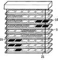
In advantageous embodiment, OLED by segmentation to provide side by side some OLED sections on each louver board.Can be luminous independently of each other thereby these OLED sections are electrically contacted separately.This separating controlling allows to utilize these OLED sections to produce interested illumination effect with suitable control device.The OLED section also can and be arranged such that whole daylight deflection system can be used for sign board by the adjustment size, for example as the indoor or outdoors display, such as being used for create atmosphere, being used for advertisement, perhaps as information or amusement medium.
In another embodiment of the present invention; Louver board is designed to have at least two parts; Its first is arranged and forms and stops with higher angle of incidence (promptly; High profile angle (profile angle) with the sun) daylight of incident, its second portion are arranged and form the sunshine deflection with low angle of incidence (that is, with low profile angle) incident is made it towards indoor ceiling.First provides the first surface zone of directed outwards.Second portion connects towards inside, has suitable surface to be used for the deflection sunshine.OLED or photoconduction with microstructured surface are disposed in this second surface zone.
In another embodiment, additional OLED is integrated or is attached in the perhaps part of the directed outwards in first surface zone of first surface zone.These additional OLED are preferably by micro-structural, but by segmentation and be controlled separately, operate to allow this deflection system to can be used for nameplate, for example as display.Use the segmentation fully of directed outwards or the OLED of pixelation, this light deflection system can be used as display that is used for advertisement or information or the amusement medium that uses as the outside people of confession.This needs control device to come dynamically to control each OLED section so that the display effect of expectation to be provided.
Be coupled among the embodiment of photoconduction of LED in use, LED preferably is arranged in louvered one or two short side, couples light in the photoconduction with what will launch.Photoconduction preferably includes inside or the exterior light diffusing structure passes Free Surface to the outside emission of photoconduction to improve transmission light.These structures can spread all over photoconduction and distribute equably so that uniform light emission to be provided.Also can this structure only be provided partly according to even or inhomogeneous pattern, be used for with the local emission of the similar structure of desired pattern.This structure can be single particle or the groups of grains that is embedded in the photoconduction.This structure also can be formed by coating that is applied to light guide surface or scattering layer.The light emission of passing the surface also can receive the influence of the microstructure on the light guide surface.
Daylight deflection system according to the present invention is that the artificial light sources of OLED or LED coupling photoconduction is integrated in the parts of deflection system and has utilized the particular community of OLED and photoconduction with form, has especially utilized the micro-structural possibility of substrate.Through OLED or photoconduction are integrated in the louver board of deflection system, the designing requirement of deflection profile is significantly loosened.Other obsolete surfaces can be utilized to improve room illumination and to allow the create atmosphere effect.In addition, OLED can be arranged in the surface of directed outwards and be divided into away minor segment or sheet (tile).Through with display this pixelation deflection system of dynamic driving similarly, this deflection system can be used for for example advertisement or such as other incidents of light effect.
Of the present invention these will manifest and are able to set forth with reference to these embodiment with other aspects according to the described embodiment of hereinafter.
Description of drawings
To combine accompanying drawing to describe the daylight deflection system that is proposed below, and not limit the protection domain that is defined by the claims through example.Accompanying drawing illustrates:
Fig. 1 is according to the schematic side elevation of daylight deflection system of the present invention;
Fig. 2 is according to another sketch map of daylight deflection system of the present invention;
The sketch map of the OLED that uses in Fig. 3 daylight deflection system of the present invention; And
Fig. 4 is according to the sketch map of the LED coupling photoconduction that uses in the daylight deflection system of the present invention.
The specific embodiment
The daylight deflection system that is proposed is schematically described in Fig. 1, and Fig. 1 illustrates a possible example of this deflection system.This figure illustrates exemplary deflection system 1 with lateral view.Deflection system 1 is arranged inwindow 2 back, and this window is separated the outside 3 of building with inner 4.Deflection system is made up of somelouver boards 5 of opaque material, and these louver boards are arranged to the horizontal-extending at the window place in parallel to each other according to known way.In Fig. 1, theselouver boards 5 extend perpendicular to paper ground with its longest ennation.
From figure, can find out thatlouver board 5 comprises two parts with difference in functionality.Outboard Sections with groove shape structure is designed to reflecting back into the outside with respect tohorizontal direction 19 with the sunshine of steep angle incident.This sunshine 6 that is stopped is denoted as a single sun light beam in the drawings.The inboard second portion oflouver board 5 is arranged and forms making it the ceiling towards building or house interior with respect tohorizontal direction 19 with the sunshine deflection than low angle incident.Thesunshine 7 of this deflection also is denoted as a single sun light beam in the drawings.
In current example, OLED 8 is attached to sunshine deflection is made it the surface towards thelouver board 5 of the indoor ceiling in room.In order to ensure this deflection, OLED 8 in their surface by micro-structural to allow or even to improve this deflection.This microstructure is not described in Fig. 1.On the other hand, if sunshine shortage for example, particularly when night, OLED 8 can be actuated to launch light and be used for inner fill light.In this case, like another single light beam institute signs among the figure, by a part of direct irradiation ceiling of theartificial light 20 of OLED 8 emissions, and another part up the at of proximate louver reflected by downward.OLED 8 is electrically contacted through being integrated in the thin conductor in thelouver board 5.
In the exemplary embodiment of Fig. 1, be used to stop or the first of thelouver board 5 of back reflection sunshine provides the surface portion of directed outwards 3, under this situation downward direction.The other OLED 9 of micro-structural is not attached to these surface portions in its surface, so that outside illumination effects to be provided at night.Thereby can and being electrically contacted by segmentation, these other OLED 9 driven individually.In this case, the OLED section can such dynamically driving of similar display think that the outside provides expectation information, effect or advertisement.
TheOLED 8 of micro-structural can be by similar manner by segmentation and drive, thereby this demonstration is provided for inside.
Fig. 2 is the sketch map that the possible segmentation of OLED is shown.OLED section 10 is arranged on thelouver board 5 abreast and can by control thereby the display light system be provided individually.Be used to stop with the needed geometric format of the louver board of deflection daylight not shown at this.
Fig. 3 illustrates the example of theOLED 8 that can in the deflection system according to Fig. 1, use with schematic sectional drawing.OLED 8 by be folded in two electrodes 11, active luminous organic material 13 between 12 is formed.As known in the art, this sandwich is installed on the optical transparent substrate 14.Negative electrode 12 is preferably processed by optical reflection metallic alloy, for example aluminium.Anode 11 can by optically transparent material, for example ITO process or the structure that can form similar grid to allow the light that transmission was produced.This OLED is also referred to as end emission OLED, because emission is directed passing the transparency carrier of being processed by glass or optical clear plastic material 14.Can see from Fig. 3, the surface of transparency carrier 14 by micro-structural to form microprism 15.Thereby thesemicroprisms 15 are made by the adjustment size and are deflected the interior ceiling towards the room of having arranged deflection system with the lip-deep daylight that is incident on this substrate than low angle.The physical mechanism of this deflection is daylight at the interface total reflection between air andmicroprism 15.
In the deflection system that is proposed, this OLED 8 can be for example through thegluing louver board 5 that is attached to.Also can directly form OLED louver board 5.In this case, substrate 14 must be enough firmly to allow it to be used as louver board and bottom electrode 12 must be opaque fully with block light.In such embodiment, also the supplementary protection layer can be provided on negative electrode 12.
Fig. 4 illustrates the example thatphotoconduction 16 is attached to louver board 5.The top of Fig. 4 is divided into the exemplary sectional drawing of thesimplification louver board 5 with attached photoconduction 16.This tangent plane is the longitudinal axis along louver board 5.At two short sides oflouver board 5,LED 17 is arranged to artificial light is coupled in the photoconduction 16.Photoconduction 16 is processed by the glass or the optical clear plastic material of the application layer with reflective coating 18.This layer guarantees that the light through photoconduction is also passed the upper surface ofphotoconduction 16 by emission.
The lower part of Fig. 4 illustrates the vertical view of this structure.From then on the vertical view ofphotoconduction 16 can be seen in the example, is arranged in someLED 17 of louvered shorter lateral sides of such.Can use thisphotoconduction 16 to come the OLED 8 of alternate figures 1 together with theLED 17 that is used for generating light.In the example of Fig. 4, the surface texture ofphotoconduction 16 is not shown.This structure is identical with the surface texture of the substrate 14 of Fig. 3.
As an example, the required electric power of driving OLED and/or led light source can be supplied through thestay cord 21 that is connected to power supply.Stay cord can be processed perhaps by conductive material can comprise lead.In another embodiment, power supply can be integrated in the louver board 5.Those skilled in the art also can consider driving voltage is fed to the alternative scheme of light source.
Although in accompanying drawing and above stated specification, at length illustrated and described the present invention, it is illustrative or exemplary and nonrestrictive that these explanations and description should be regarded as, and the invention is not restricted to the disclosed embodiments.In the preceding text and the different embodiment that describe in the claim also can make up.Through research accompanying drawing, open and accompanying claims, those skilled in the art are appreciated that and realize other modification to the disclosed embodiments when putting into practice the present invention for required protection.For example, photoconduction can not only be attached to louver board, can also form this louver board.Generally speaking, louver board can be fix or movably, particularly can be around the rotation of its longitudinal axis.Rotatable louver board allows further to adjust the angle of incident sunshine.Although in the example shown, the louver board surface is a flat surfaces, but these surfaces also can be crooked.
In claim, indefinite article " " or " one " (" a " or " an ") do not get rid of a plurality of.In mutually different dependent claims, enumerate some measure this minimum fact and do not represented advantageously to use the combination of these measures.Any Reference numeral in the claim should not be interpreted as the scope that limits these claims.
Reference numerals list
1 daylight deflection system
2 windows
3 outsides
4 inside
5 louver boards
The sunshine that 6 quilts are stopped
7 sunshines that are deflected
8 have the OLED of microstructured surface
9 are used for the OLED of exterior lighting
The 10OLED section
11 anodes
12 smooth reflective cathode
13 luminescent materials
14 optical transparent substrates
15 microprisms
16 photoconductions
17LED
18 smooth reflective coating layers
19 horizontal directions
20 artificial lights
21 stay cords
Claims (9)
1. daylight deflection system,
The layout that comprises louver board (5), said louver board is arranged and forms:
-stop from the outside (3) with respect to the daylight of horizontal direction (19) with higher angle of incidence incident,
-will (3) make it towards indoor ceiling from the outside with respect to the daylight deflection of this horizontal direction (19) with low angle of incidence incident, and
-allow the visual communication of along continuous straight runs (19) at least,
Wherein OLED (8) or the optical light guides (16) that is coupled to LED (17) are attached to said louver board (5) or are integrated in the said louver board (5), said OLED (8) or optical light guides (16) in the surface by micro-structural so that this daylight deflection is made it towards this indoor ceiling.
2. daylight deflection system as claimed in claim 1,
Wherein said OLED (8) is located to provide some OLED sections (10) side by side by segmentation at each louver board (5), and said OLED section (10) is controlled luminous with independently of each other.
3. according to claim 1 or claim 2 daylight deflection system,
Wherein each louver board (5) comprises at least two parts; The said louvered first of (3) forms and has the first surface zone that stops with the daylight of high angle incident in the outside, and the said louvered second portion in inboard (4) forms and has the second surface zone that is used for making it with the daylight deflection than low angle incident towards this indoor ceiling.
4. daylight deflection system as claimed in claim 3,
Wherein said OLED (8) or photoconduction (16) are disposed in this second surface zone.
5. daylight deflection system as claimed in claim 4,
Wherein other OLED (9) is arranged in the part of the directed outside in this first surface zone or this first surface zone; Said other OLED (9) is by segmentation and be separately controlled, thereby allows the said other OLED (9) of this deflection system to operate as display.
6. daylight deflection system as claimed in claim 1,
Wherein said OLED (8) is provided plurality of single controlled OLED section (10) by segmentation, operates as display with the OLED (8) that allows this deflection system.
7. daylight deflection system as claimed in claim 1,
Wherein said OLED (8) or photoconduction (16) by micro-structural to form microprism (15) in the surface.
8. daylight deflection system as claimed in claim 1,
Wherein said photoconduction (16) comprises light scattering structure (18).
9. daylight deflection system as claimed in claim 1,
Wherein light scattering structure (18) is applied to the surface of said photoconduction (16).
Applications Claiming Priority (3)
| Application Number | Priority Date | Filing Date | Title |
|---|---|---|---|
| EP07106632.8 | 2007-04-20 | ||
| EP07106632 | 2007-04-20 | ||
| PCT/IB2008/051455WO2008129467A1 (en) | 2007-04-20 | 2008-04-16 | Daylight deflection system with integrated artificial light source |
Publications (2)
| Publication Number | Publication Date |
|---|---|
| CN101663456A CN101663456A (en) | 2010-03-03 |
| CN101663456Btrue CN101663456B (en) | 2012-08-15 |
Family
ID=39588565
Family Applications (1)
| Application Number | Title | Priority Date | Filing Date |
|---|---|---|---|
| CN200880012765XAExpired - Fee RelatedCN101663456B (en) | 2007-04-20 | 2008-04-16 | Daylight deflection system with integrated artificial light source |
Country Status (6)
| Country | Link |
|---|---|
| US (1) | US8104921B2 (en) |
| EP (1) | EP2148971B1 (en) |
| JP (1) | JP5328764B2 (en) |
| CN (1) | CN101663456B (en) |
| TW (1) | TW200912117A (en) |
| WO (1) | WO2008129467A1 (en) |
Families Citing this family (19)
| Publication number | Priority date | Publication date | Assignee | Title |
|---|---|---|---|---|
| DE102008002219B4 (en)* | 2008-06-04 | 2014-11-20 | Mediabiose Gmbh | Venetian blind device and arrangement with a majority of Venetian blind devices |
| CN101832093B (en)* | 2010-03-18 | 2011-09-21 | 杭州欧卡索拉科技有限公司 | Three-blade combined louver blade |
| BE1019367A3 (en)* | 2010-06-08 | 2012-06-05 | Saint Light Technology Corp | ADJUSTABLE DISPLAY DEVICE. |
| CN101899942B (en)* | 2010-07-19 | 2012-05-23 | 杭州欧卡索拉科技有限公司 | Dual-functional louver blade |
| US8305678B2 (en)* | 2010-12-29 | 2012-11-06 | Delphi Technologies, Inc. | Dual view display system |
| EP2474967A1 (en)* | 2011-01-06 | 2012-07-11 | Koninklijke Philips Electronics N.V. | Luminescent-OLED light collector signage panel |
| US8926119B2 (en) | 2011-08-04 | 2015-01-06 | Universal Display Corporation | Extendable light source with variable light emitting area |
| US8760068B1 (en)* | 2011-09-07 | 2014-06-24 | Iml International | Driving LEDs in LCD backlight |
| US8611011B2 (en)* | 2012-04-20 | 2013-12-17 | Suncentral, Inc. | Dual-stage sunlight redirection system |
| US9080763B2 (en) | 2012-05-17 | 2015-07-14 | GE Lighting Solutions, LLC | Edge lit luminaires for windows |
| US9897289B2 (en) | 2014-06-04 | 2018-02-20 | Abl Ip Holdings Llc | Light fixture with photosensor-activated adjustable louver assembly and color temperature control |
| US9797141B2 (en) | 2014-06-04 | 2017-10-24 | Abl Ip Holding Llc | Light fixture with photosensor-activated adjustable louver assembly |
| US10874006B1 (en) | 2019-03-08 | 2020-12-22 | Abl Ip Holding Llc | Lighting fixture controller for controlling color temperature and intensity |
| US11873682B2 (en) | 2019-03-27 | 2024-01-16 | James F. Brown | Light absorbing and light emitting devices, light admitting assemblies, and methods of absorbing and emitting light |
| US12007111B2 (en) | 2019-10-18 | 2024-06-11 | Hunter Douglas Inc. | Lighted architectural-structure covering |
| CN110847794A (en)* | 2019-11-18 | 2020-02-28 | 博讯光电科技(合肥)有限公司 | Louvered mural display curtain |
| CN116981825A (en) | 2021-03-23 | 2023-10-31 | 亨特道格拉斯公司 | Lighting building structure covering |
| KR102730807B1 (en)* | 2021-10-27 | 2024-11-15 | 주식회사 바이솔라 | Variable Type Light Shelf Illumination |
| WO2024134249A1 (en)* | 2022-12-19 | 2024-06-27 | Morgan Solar Inc. | Solar window blind systems |
Citations (5)
| Publication number | Priority date | Publication date | Assignee | Title |
|---|---|---|---|---|
| CN88201883U (en)* | 1988-03-17 | 1988-12-21 | 华南理工大学 | Reflecting louvered curtain |
| DE10016587A1 (en)* | 2000-04-04 | 2001-10-18 | Helmut Koester | Light deflection system for illuminating room with artificial and natural light has surfaces deflecting artificial light to ceiling and floor |
| DE10344213A1 (en)* | 2003-09-22 | 2005-07-21 | Angela Karning | Shading and lightening device e.g. for lightening living space, offices, green houses, has one side coated with semiconductor layer and coating applied using silicon technology and AlGaInP and coating applied with OLED |
| DE102004041224A1 (en)* | 2004-08-26 | 2006-03-09 | Müller, Simon | Sun blind for e.g. interior lighting, has plane light emitting material arranged on lamellas, and electro-luminance foils found in convex top side of lamellas of sun-blind, where one of lamellas is coupled with control electronic circuit |
| WO2006123283A2 (en)* | 2005-05-17 | 2006-11-23 | Koninklijke Philips Electronics N.V. | Daylight shielding device |
Family Cites Families (18)
| Publication number | Priority date | Publication date | Assignee | Title |
|---|---|---|---|---|
| US2689026A (en)* | 1949-10-18 | 1954-09-14 | Neo Ray Products Inc | Louvered ceiling construction with interengaging louver units and side rails |
| US2859334A (en)* | 1954-09-09 | 1958-11-04 | Edwin F Guth Company | Louvers |
| JPS573985A (en)* | 1980-06-11 | 1982-01-09 | Toshiba Electric Equip | Lighting apparatus utilizing daylight |
| CA2045410A1 (en) | 1989-02-28 | 1990-08-29 | Helmut Koster | Light guidance system for the illumination of an interior area |
| JP2001022298A (en)* | 1999-07-05 | 2001-01-26 | Seiko Instruments Inc | Display panel and display device |
| JP2001082058A (en)* | 1999-09-09 | 2001-03-27 | Sony Corp | Blind device |
| JP2001176315A (en)* | 1999-12-15 | 2001-06-29 | Mitsubishi Rayon Co Ltd | Planar lighting device and tabletop lighting device using the same |
| DE20018808U1 (en) | 2000-11-03 | 2001-02-15 | Rogal Peter | Illumination by LED (Light Emitting Diodes) or other incandescent bodies in doors, gates, windows, baseboards and ceiling moldings as well as their frames and profiles |
| DE10231502A1 (en) | 2002-07-12 | 2004-01-22 | Thomas Emde | window element |
| US7182480B2 (en)* | 2003-03-05 | 2007-02-27 | Tir Systems Ltd. | System and method for manipulating illumination created by an array of light emitting devices |
| DE20313873U1 (en) | 2003-09-06 | 2004-01-15 | Ruotolo, Bruno | Artistically decorated glass door or window, has lighting devices, such as LCD, LED or light-emitting foil introduced in to glass and provided with power supply |
| US7057821B2 (en) | 2003-10-28 | 2006-06-06 | Robert Zincone | Integrated artificial and natural lighting system |
| DE102004026730A1 (en) | 2004-05-28 | 2005-12-15 | Manfred Kluth | Surface with electrical consumers, in particular bulbs |
| DE202004013324U1 (en) | 2004-08-26 | 2004-11-11 | Müller, Simon | Light source for interior room lighting, has flat light emitting material preferably electroluminescent foils arranged in the strips of a venetian blind |
| JP3977837B2 (en)* | 2004-12-27 | 2007-09-19 | 株式会社韓国サイン | Blind type display device using LED |
| US7182547B1 (en)* | 2005-08-25 | 2007-02-27 | Acuity Brands, Inc. | Bollard lamp |
| DE202005018159U1 (en) | 2005-11-22 | 2006-03-09 | Moser, Helmut, Dipl.-Volksw. | Connecting disc, has transparent plates connected with one another with its sides by transparent, thermoplastic laminated film under pressure and temperature, where light condenser is formed by insulating characteristic of film |
| US7934851B1 (en)* | 2008-08-19 | 2011-05-03 | Koninklijke Philips Electronics N.V. | Vertical luminaire |
- 2008
- 2008-04-16CNCN200880012765XApatent/CN101663456B/ennot_activeExpired - Fee Related
- 2008-04-16USUS12/595,656patent/US8104921B2/ennot_activeExpired - Fee Related
- 2008-04-16WOPCT/IB2008/051455patent/WO2008129467A1/enactiveApplication Filing
- 2008-04-16EPEP08737877.4Apatent/EP2148971B1/ennot_activeNot-in-force
- 2008-04-16JPJP2010503649Apatent/JP5328764B2/ennot_activeExpired - Fee Related
- 2008-04-18TWTW097114330Apatent/TW200912117A/enunknown
Patent Citations (5)
| Publication number | Priority date | Publication date | Assignee | Title |
|---|---|---|---|---|
| CN88201883U (en)* | 1988-03-17 | 1988-12-21 | 华南理工大学 | Reflecting louvered curtain |
| DE10016587A1 (en)* | 2000-04-04 | 2001-10-18 | Helmut Koester | Light deflection system for illuminating room with artificial and natural light has surfaces deflecting artificial light to ceiling and floor |
| DE10344213A1 (en)* | 2003-09-22 | 2005-07-21 | Angela Karning | Shading and lightening device e.g. for lightening living space, offices, green houses, has one side coated with semiconductor layer and coating applied using silicon technology and AlGaInP and coating applied with OLED |
| DE102004041224A1 (en)* | 2004-08-26 | 2006-03-09 | Müller, Simon | Sun blind for e.g. interior lighting, has plane light emitting material arranged on lamellas, and electro-luminance foils found in convex top side of lamellas of sun-blind, where one of lamellas is coupled with control electronic circuit |
| WO2006123283A2 (en)* | 2005-05-17 | 2006-11-23 | Koninklijke Philips Electronics N.V. | Daylight shielding device |
Also Published As
| Publication number | Publication date |
|---|---|
| EP2148971A1 (en) | 2010-02-03 |
| TW200912117A (en) | 2009-03-16 |
| WO2008129467A1 (en) | 2008-10-30 |
| EP2148971B1 (en) | 2014-12-31 |
| US20100067228A1 (en) | 2010-03-18 |
| WO2008129467A8 (en) | 2009-11-19 |
| JP5328764B2 (en) | 2013-10-30 |
| JP2010525519A (en) | 2010-07-22 |
| CN101663456A (en) | 2010-03-03 |
| US8104921B2 (en) | 2012-01-31 |
Similar Documents
| Publication | Publication Date | Title |
|---|---|---|
| CN101663456B (en) | Daylight deflection system with integrated artificial light source | |
| CN105546364A (en) | Led-array system | |
| CN102024387B (en) | High transparent LED (light emitting diode) display module | |
| CN102667553A (en) | Transparent emissive window element | |
| CN102549332A (en) | Light output sticker | |
| US20160003445A1 (en) | Artistic lighting module and method for manufacturing the same | |
| KR102065937B1 (en) | LED Advertising Device | |
| JP2004527676A (en) | Public buildings with illuminated glass plates | |
| NZ227091A (en) | Transparent panel with embedded discharge lamp | |
| JP2012014834A (en) | Waterproof plane light-emitting plate emitting light with led edge light | |
| KR101285608B1 (en) | Signboard for using dye-sensitized solar cell | |
| KR102243854B1 (en) | LED billboard with solar power generation | |
| CN111200032A (en) | A solar cell module and BIPV curtain wall | |
| US9371978B2 (en) | Solar panel assembly with a lighting pattern and including conductors sandwiching a dielectric substance | |
| KR100998702B1 (en) | LED fluorescent lamp with variable reflector | |
| CN105303981A (en) | Display unit of LED display screen | |
| CN1584957A (en) | LED subdued planar panel displaying (illumination) devices | |
| CN203856097U (en) | Glass luminous brick wall | |
| JP2015115199A (en) | Building material unit | |
| KR101238717B1 (en) | Display device | |
| KR101257751B1 (en) | Guide board using led | |
| CN213366611U (en) | Photovoltaic module | |
| KR20180003057U (en) | Smart Illumination System using Dye-Sensitized Solar Cell | |
| CN1728203A (en) | Individualized IED illuminatino indicator light (plate) in underground parking area | |
| RU86616U1 (en) | DECORATIVE LIGHTING STRUCTURE FOR REGISTRATION OF ELEMENTS OF RESIDENTIAL OR OFFICE ARCHITECTURE |
Legal Events
| Date | Code | Title | Description |
|---|---|---|---|
| C06 | Publication | ||
| PB01 | Publication | ||
| C10 | Entry into substantive examination | ||
| SE01 | Entry into force of request for substantive examination | ||
| C14 | Grant of patent or utility model | ||
| GR01 | Patent grant | ||
| CP01 | Change in the name or title of a patent holder | Address after:Holland Ian Deho Finn Patentee after:KONINKLIJKE PHILIPS N.V. Address before:Holland Ian Deho Finn Patentee before:Koninklijke Philips Electronics N.V. | |
| CP01 | Change in the name or title of a patent holder | ||
| TR01 | Transfer of patent right | Effective date of registration:20170306 Address after:Eindhoven Patentee after:KONINKLIJKE PHILIPS N.V. Address before:Holland Ian Deho Finn Patentee before:KONINKLIJKE PHILIPS N.V. | |
| TR01 | Transfer of patent right | ||
| CF01 | Termination of patent right due to non-payment of annual fee | Granted publication date:20120815 Termination date:20180416 | |
| CF01 | Termination of patent right due to non-payment of annual fee |