CN101663060B - Injection device for delivering a medication - Google Patents
Injection device for delivering a medicationDownload PDFInfo
- Publication number
- CN101663060B CN101663060BCN200880012589XACN200880012589ACN101663060BCN 101663060 BCN101663060 BCN 101663060BCN 200880012589X ACN200880012589X ACN 200880012589XACN 200880012589 ACN200880012589 ACN 200880012589ACN 101663060 BCN101663060 BCN 101663060B
- Authority
- CN
- China
- Prior art keywords
- injection device
- insertion sleeve
- surface portion
- sleeve
- housing part
- Prior art date
- Legal status (The legal status is an assumption and is not a legal conclusion. Google has not performed a legal analysis and makes no representation as to the accuracy of the status listed.)
- Active
Links
Images


Classifications
- A—HUMAN NECESSITIES
- A61—MEDICAL OR VETERINARY SCIENCE; HYGIENE
- A61M—DEVICES FOR INTRODUCING MEDIA INTO, OR ONTO, THE BODY; DEVICES FOR TRANSDUCING BODY MEDIA OR FOR TAKING MEDIA FROM THE BODY; DEVICES FOR PRODUCING OR ENDING SLEEP OR STUPOR
- A61M5/00—Devices for bringing media into the body in a subcutaneous, intra-vascular or intramuscular way; Accessories therefor, e.g. filling or cleaning devices, arm-rests
- A61M5/178—Syringes
- A61M5/31—Details
- A61M5/315—Pistons; Piston-rods; Guiding, blocking or restricting the movement of the rod or piston; Appliances on the rod for facilitating dosing ; Dosing mechanisms
- A61M5/31533—Dosing mechanisms, i.e. setting a dose
- A61M5/31545—Setting modes for dosing
- A61M5/31548—Mechanically operated dose setting member
- A61M5/3155—Mechanically operated dose setting member by rotational movement of dose setting member, e.g. during setting or filling of a syringe
- A61M5/31551—Mechanically operated dose setting member by rotational movement of dose setting member, e.g. during setting or filling of a syringe including axial movement of dose setting member
- A—HUMAN NECESSITIES
- A61—MEDICAL OR VETERINARY SCIENCE; HYGIENE
- A61M—DEVICES FOR INTRODUCING MEDIA INTO, OR ONTO, THE BODY; DEVICES FOR TRANSDUCING BODY MEDIA OR FOR TAKING MEDIA FROM THE BODY; DEVICES FOR PRODUCING OR ENDING SLEEP OR STUPOR
- A61M5/00—Devices for bringing media into the body in a subcutaneous, intra-vascular or intramuscular way; Accessories therefor, e.g. filling or cleaning devices, arm-rests
- A61M5/178—Syringes
- A61M5/31—Details
- A61M5/315—Pistons; Piston-rods; Guiding, blocking or restricting the movement of the rod or piston; Appliances on the rod for facilitating dosing ; Dosing mechanisms
- A61M5/31533—Dosing mechanisms, i.e. setting a dose
- A61M5/31545—Setting modes for dosing
- A61M5/31548—Mechanically operated dose setting member
- A61M5/31556—Accuracy improving means
- A—HUMAN NECESSITIES
- A61—MEDICAL OR VETERINARY SCIENCE; HYGIENE
- A61M—DEVICES FOR INTRODUCING MEDIA INTO, OR ONTO, THE BODY; DEVICES FOR TRANSDUCING BODY MEDIA OR FOR TAKING MEDIA FROM THE BODY; DEVICES FOR PRODUCING OR ENDING SLEEP OR STUPOR
- A61M5/00—Devices for bringing media into the body in a subcutaneous, intra-vascular or intramuscular way; Accessories therefor, e.g. filling or cleaning devices, arm-rests
- A61M5/178—Syringes
- A61M5/31—Details
- A61M5/315—Pistons; Piston-rods; Guiding, blocking or restricting the movement of the rod or piston; Appliances on the rod for facilitating dosing ; Dosing mechanisms
- A61M5/31565—Administration mechanisms, i.e. constructional features, modes of administering a dose
- A61M5/31566—Means improving security or handling thereof
- A61M5/31573—Accuracy improving means
- A—HUMAN NECESSITIES
- A61—MEDICAL OR VETERINARY SCIENCE; HYGIENE
- A61M—DEVICES FOR INTRODUCING MEDIA INTO, OR ONTO, THE BODY; DEVICES FOR TRANSDUCING BODY MEDIA OR FOR TAKING MEDIA FROM THE BODY; DEVICES FOR PRODUCING OR ENDING SLEEP OR STUPOR
- A61M2205/00—General characteristics of the apparatus
- A61M2205/58—Means for facilitating use, e.g. by people with impaired vision
- A61M2205/583—Means for facilitating use, e.g. by people with impaired vision by visual feedback
- A61M2205/585—Means for facilitating use, e.g. by people with impaired vision by visual feedback having magnification means, e.g. magnifying glasses
- A—HUMAN NECESSITIES
- A61—MEDICAL OR VETERINARY SCIENCE; HYGIENE
- A61M—DEVICES FOR INTRODUCING MEDIA INTO, OR ONTO, THE BODY; DEVICES FOR TRANSDUCING BODY MEDIA OR FOR TAKING MEDIA FROM THE BODY; DEVICES FOR PRODUCING OR ENDING SLEEP OR STUPOR
- A61M5/00—Devices for bringing media into the body in a subcutaneous, intra-vascular or intramuscular way; Accessories therefor, e.g. filling or cleaning devices, arm-rests
- A61M5/178—Syringes
- A61M5/24—Ampoule syringes, i.e. syringes with needle for use in combination with replaceable ampoules or carpules, e.g. automatic
- Y—GENERAL TAGGING OF NEW TECHNOLOGICAL DEVELOPMENTS; GENERAL TAGGING OF CROSS-SECTIONAL TECHNOLOGIES SPANNING OVER SEVERAL SECTIONS OF THE IPC; TECHNICAL SUBJECTS COVERED BY FORMER USPC CROSS-REFERENCE ART COLLECTIONS [XRACs] AND DIGESTS
- Y10—TECHNICAL SUBJECTS COVERED BY FORMER USPC
- Y10T—TECHNICAL SUBJECTS COVERED BY FORMER US CLASSIFICATION
- Y10T29/00—Metal working
- Y10T29/49—Method of mechanical manufacture
- Y10T29/49826—Assembling or joining
Landscapes
- Health & Medical Sciences (AREA)
- Vascular Medicine (AREA)
- Engineering & Computer Science (AREA)
- Anesthesiology (AREA)
- Biomedical Technology (AREA)
- Heart & Thoracic Surgery (AREA)
- Hematology (AREA)
- Life Sciences & Earth Sciences (AREA)
- Animal Behavior & Ethology (AREA)
- General Health & Medical Sciences (AREA)
- Public Health (AREA)
- Veterinary Medicine (AREA)
- Infusion, Injection, And Reservoir Apparatuses (AREA)
- Medical Preparation Storing Or Oral Administration Devices (AREA)
Abstract
Translated fromChinese
Description
Translated fromChinese技术领域technical field
本发明涉及一种用于分配/输送药物的注射装置。The present invention relates to an injection device for dispensing/delivering medicaments.
发明内容Contents of the invention
本发明的目的在于提供一种注射装置,利用该注射装置可以改善对待分配的注射剂量的设定。The object of the present invention is to provide an injection device with which the setting of the injection dose to be dispensed can be improved.
本发明的另一目的在于提供一种医用注射装置,利用该注射装置可以为使用者改善计量精度。Another object of the present invention is to provide a medical injection device, which can improve metering accuracy for users.
该目的由独立权利要求的特征实现。其它的实施方式由引用这些独立权利要求的从属权利要求给出。This object is achieved by the features of the independent claims. Further embodiments are given by the dependent claims referencing these independent claims.
通过根据本发明的解决方案,实现了分配机构和/或剂量设定机构的机械加强,进而实现了设定剂量的可读性更高的设定机制。By means of the solution according to the invention, a mechanical reinforcement of the dispensing mechanism and/or of the dose setting mechanism is achieved, thereby enabling a more readable setting mechanism of the set dose.
通过根据本发明的解决方案的一种实施方式可实现对注射装置的壳体内部的有利的防污密封。An advantageous dirt-tight sealing of the housing interior of the injection device can be achieved by one embodiment of the solution according to the invention.
此外,根据本发明,可通过由对突起部分和缺口的相应尺寸设计而在该突起部分与缺口之间形成的配合连接,将插入套筒插入到远端壳体件内,从而能更精确地设定指示套筒的轴向位置。Furthermore, according to the invention, the insertion sleeve can be inserted into the distal housing part by means of a fitting connection formed between the protrusion and the notch by corresponding dimensioning of the protrusion and the notch, thereby enabling a more precise Set the axial position of the indicating sleeve.
因此能够补偿注射装置的结构元件的可能的制造误差。Possible manufacturing tolerances of the structural elements of the injection device can thus be compensated for.
因此,本发明的主题是用于分配药物的注射装置,包括:The subject of the invention is therefore an injection device for dispensing medicaments, comprising:
-小筒模块,该小筒模块用于接纳含有注射制剂的小筒/药瓶(Kartusche),该小筒可能具有用于安装一针头的接纳部,该针头安装在小筒的端部上,注射制剂能通过该针头被注射,- a cartridge module for receiving a cartridge/vial (Kartusche) containing an injection preparation, which cartridge may have a receptacle for mounting a needle mounted on the end of the cartridge, Injectable preparations can be injected through the needle,
-分配机构,通过操作该分配机构实现注射制剂的分配,- a dispensing mechanism by which the dispensing of the injectable preparation is effected,
-剂量设定机构,该剂量设定机构用于设定在操作分配机构时分配的注射制剂的剂量,其中所述剂量设定机构包括:接纳分配机构的至少一部分的壳体件、能至少部分地插入远端壳体件中并能在该远端壳体件中转动的指示套筒、和能插入壳体件中的插入套筒,- a dose setting mechanism for setting a dose of an injectable formulation dispensed upon operation of the dispensing mechanism, wherein said dose setting mechanism comprises: a housing member receiving at least part of the dispensing mechanism, able to at least partially An indication sleeve that can be inserted into the distal housing part and can rotate in the distal housing part, and an insertion sleeve that can be inserted into the housing part,
其特征在于,It is characterized in that,
-所述插入套筒具有在外表面上突起的表面部分,该突起的表面部分至少局部形成为可透视的或透明的,以及- said insertion sleeve has a raised surface portion on the outer surface which is at least partially formed see-through or transparent, and
-所述壳体件具有一在壳体件的远端边缘上开口的缺口,用以从所述缺口的开口侧接纳所述突起的表面部分,其中,壳体件以不能相对转动的方式接纳在插入状态下的插入套筒。- the housing member has a notch open on the distal edge of the housing member for receiving the protruding surface portion from the open side of the notch, wherein the housing member is received in a relatively non-rotatable manner Insertion sleeve in inserted state.
在本发明的一种实施方式中,所述缺口的在远端壳体件的轴向方向上延伸的边缘的相互面对的内边缘彼此相距一距离,在该距离下所述缺口边缘与所述突起的表面部分的相应侧边缘在此形成间隙配合、过渡配合或过盈配合/压配合。In one embodiment of the invention, the mutually facing inner edges of the edges of the notch extending in the axial direction of the distal housing part are at a distance from each other at which the notch edge and the The corresponding side edges of the raised surface parts form a clearance fit, a transition fit or an interference fit/press fit here.
在本发明的另一种实施方式中,所述突起的表面部分的对接边缘轮廓线、和相应缺口的对接边缘的轮廓线沿直线在周向方向上延伸。In another embodiment of the invention, the outline of the abutment edge of the surface portion of the protrusion, and the outline of the abutment edge of the corresponding notch extend along a straight line in the circumferential direction.
优选的是,所述突起的表面部分的对接边缘的轮廓线、和相应的所述缺口的对接边缘的轮廓线可由两条彼此成角度延伸、尤其是以尖角相交的线段形成;或者所述突起的表面部分的纵向边缘的和对接边缘的轮廓线、和相应的缺口的纵向边缘的和对接边缘的轮廓线设计成曲线,使得突起的表面部分和缺口的轮廓至少局部形成卵形;或者所述突起的表面部分的纵向边缘的轮廓线、和相应的所述缺口的纵向边缘的轮廓线都沿直线、尤其是相互平行地延伸,而所述突起的表面部分的对接边缘的轮廓线、和相应的所述缺口的对接边缘的轮廓线设计成曲线。Preferably, the outline of the abutting edge of the protruding surface portion, and correspondingly the outline of the abutting edge of the notch, may be formed by two line segments extending at an angle to each other, especially intersecting at a sharp angle; or the the outlines of the longitudinal and abutting edges of the raised surface portion and of the corresponding longitudinal and abutting edges of the indentation are curved such that the outlines of the raised surface portion and the indentation at least partially form an oval shape; or The outlines of the longitudinal edges of the protruding surface portions and correspondingly the contours of the longitudinal edges of the notches extend along a straight line, in particular parallel to each other, while the contours of the abutting edges of the protruding surface portions, and Correspondingly, the outline of the abutting edge of the notch is designed as a curve.
在根据本发明的注射装置的另一种实施方式中,在所述突起的表面部分的上侧上形成有另一凸起,尤其是用于以所述突起的表面部分的透明部分实现放大镜效果。In a further embodiment of the injection device according to the invention, a further protrusion is formed on the upper side of the raised surface part, in particular for realizing a magnifying glass effect with the transparent part of the raised surface part .
在根据本发明的注射装置的又一种实施方式中,提供一锁定装置,该锁定装置用于当所述插入套筒被向壳体件中推入其终端位置时,使插入套筒在轴向方向上与壳体件相锁定,其中,所述锁定装置优选具有设置在壳体件内表面上的接纳结构;和设置在所述插入套筒上的、向外伸出的、与所述接纳结构共同作用的套筒锁定部。In yet another embodiment of the injection device according to the invention, a locking device is provided for locking the insertion sleeve in the shaft when said insertion sleeve is pushed into its end position into the housing part. Locking with the housing part in the direction, wherein, the locking device preferably has a receiving structure arranged on the inner surface of the housing part; A sleeve locking portion cooperating with receiving structures.
另外优选地,所述套筒锁定部具有一在壳体件的隙部中延伸的舌片/簧片,该舌片的近端端部与所述插入套筒相连接,而在所述舌片的远端端部上形成带锁定凸起的自由端部。It is also preferred that the sleeve locking part has a tongue/reed extending in the gap of the housing part, the proximal end of the tongue is connected to the insertion sleeve, while the tongue A free end with a locking projection is formed on the distal end of the sheet.
在根据本发明的注射装置中,所述接纳结构可设计成在壳体件的内表面上的凹部或设计成隙部;其中,所述接纳结构优选在周向方向上具有一预定的宽度,或被设计成在壳体件的内周面上环绕的凹部。In the injection device according to the invention, the receiving structure can be designed as a recess or as a gap on the inner surface of the housing part; wherein the receiving structure preferably has a predetermined width in the circumferential direction, Or designed as a circumferential recess on the inner peripheral surface of the housing part.
在根据本发明的注射装置中,自由端部可被设计成被分割一次或多次的、分别带有一锁定凸起的自由端部,所述接纳结构具有一个或多个凹部或隙部。In the injection device according to the invention, the free ends can be designed as free ends which are divided one or more times, each with a locking projection, and the receiving structure has one or more recesses or recesses.
在根据本发明的注射装置中,可在插入套筒上沿周向方向设置多个舌片,可设有多个相应的、设置在壳体件上的接纳结构。In the injection device according to the invention, a plurality of tongues can be provided on the insertion sleeve in the circumferential direction, and a plurality of corresponding receiving structures can be provided on the housing part.
或者,在根据本发明的注射装置中,各舌片和接纳结构对可设置在相同的轴向位置处,或在轴向方向上相互偏置。Alternatively, in the injection device according to the invention, the pairs of tongues and receiving formations may be arranged at the same axial position, or offset relative to each other in the axial direction.
此外,在根据本发明的注射装置中,壳体件可沿缺口边缘的至少一部分设置有密封件。在根据本发明的注射装置的另一种实施方式中,在插入套筒的远端端部上和/或内表面上设置一个或多个密封件。Furthermore, in the injection device according to the invention, the housing part may be provided with a seal along at least a part of the edge of the notch. In a further embodiment of the injection device according to the invention, one or more seals are provided on the distal end and/or on the inner surface of the insertion sleeve.
此外,在根据本发明的注射装置中,可设有多个突起的表面部分,相应地在插入套筒上可设有多个缺口。Furthermore, in the injection device according to the invention, a plurality of raised surface portions and correspondingly a plurality of notches on the insertion sleeve may be provided.
所述突起的表面部分可具有一个或多个标记,所述标记适于使在指示套筒上显示的、利用所述指示套筒设定的剂量更易于被读取。所述标记通过物理或化学的方式、尤其是通过印制或粘贴来施加。The raised surface portion may have one or more markings adapted to make the dose displayed on the indicating sleeve set with the indicating sleeve easier to read. The marking is applied by physical or chemical means, in particular by printing or gluing.
在根据本发明的注射装置的另一种实施方式中,所述缺口和所述突起的表面部分的纵向边缘和/或对接边缘被设计成形锁合地彼此接合。In a further embodiment of the injection device according to the invention, the notches and the longitudinal edges and/or abutment edges of the raised surface portions are designed to form-fittingly engage with each other.
本发明的另一个主题是用于根据本发明的注射装置的插入套筒,其中,所述插入套筒的外表面具有一突起的表面部分,从而在壳体件的缺口中以不能相对转动的方式接纳插入套筒,其中,所述表面部分至少局部形成可透视的或透明的。根据本发明的插入套筒的其它特别的实施方式,可以由上文中与对根据本发明的注射装置的说明相结合的实施方案得出。Another subject-matter of the invention is an insertion sleeve for an injection device according to the invention, wherein the outer surface of said insertion sleeve has a protruding surface portion, so that in a notch of a housing part in a relatively non-rotatable The insertion sleeve is received in a manner wherein the surface portion is at least partially see-through or transparent. Further special embodiments of the insertion sleeve according to the invention can be derived from the embodiments above in conjunction with the description of the injection device according to the invention.
在根据本发明的插入套筒的另一种实施方式中,将所述突起的表面部分的侧边缘设计成,与壳体件的缺口的在远端壳体件的轴向方向上延伸的边缘的内边缘形成间隙配合、过渡配合或过盈配合。其中优选地,突起的表面部分的对接边缘的轮廓线沿直线在周向方向上延伸;或者所述突起的表面部分的对接边缘的轮廓线由两条彼此成角度延伸、尤其是以尖角相交的线段形成;或者调节凸起的纵向边缘和对接边缘的轮廓线设计成曲线,使得所述突起的表面部分的轮廓至少局部形成卵形;或者突起的表面部分的纵向边缘的轮廓线沿直线、尤其是相互平行地延伸,而所述突起的表面部分的对接边缘的轮廓线设计成曲线。In a further embodiment of the insertion sleeve according to the invention, the side edges of the protruding surface parts are designed to meet the edge of the recess of the housing part extending in the axial direction of the distal housing part. The inner edge of the inner edge forms a clearance fit, transition fit or interference fit. Wherein preferably, the contour line of the abutting edge of the raised surface portion extends in the circumferential direction along a straight line; The line segment is formed; or the contour of the longitudinal edge and the butt edge of the adjustment protrusion is designed as a curve, so that the contour of the surface part of the protrusion is at least partially oval; or the contour of the longitudinal edge of the surface part of the protrusion is along a straight line, In particular, they extend parallel to one another, while the contours of the abutting edges of the raised surface parts are curved.
在根据本发明的插入套筒的又一种实施方式中,所述突起的表面部分的上侧上形成有另一凸起,尤其是用于在所述另一凸起的透明部分中实现放大镜效果。In yet another embodiment of the insertion sleeve according to the invention, a further protrusion is formed on the upper side of the raised surface part, in particular for realizing a magnifying glass in the transparent part of the further protrusion Effect.
在另一个实施方式中,根据本发明的插入套筒包括一锁定装置的一部分,用以在插入套筒的终端位置中与壳体件上的接纳结构相锁定。其中优选地,所述锁定装置的设置在插入套筒上的部分具有向外伸出的、与接纳结构共同作用的套筒锁定部。进一步优选的是,套筒锁定部具有在壳体件的隙部中延伸的舌片,该舌片的近端端部与所述插入套筒相连接,而在所述舌片的远端端部上形成带锁定凸起的自由端部。In a further embodiment, the insertion sleeve according to the invention comprises a part of a locking device for locking with a receiving structure on the housing part in the end position of the insertion sleeve. In this case, preferably, the part of the locking device which is arranged on the insertion sleeve has an outwardly protruding sleeve lock which cooperates with the receiving structure. It is further preferred that the sleeve locking portion has a tongue extending in the gap of the housing member, the proximal end of the tongue is connected to the insertion sleeve, and the distal end of the tongue is A free end with a locking protrusion is formed on the upper part.
在此,所述自由端部可设计成被分割一次或多次的、分别带有一锁定凸起的自由端部。此外,可在插入套筒上沿周向方向设置多个舌片,其中,所述多个舌片可设置在相同的轴向位置上,或在轴向方向上相互偏置。In this case, the free ends can be designed as free ends which are divided one or more times, each with a locking projection. Furthermore, a plurality of tongues can be arranged on the insert sleeve in the circumferential direction, wherein the plurality of tongues can be arranged at the same axial position or offset relative to one another in the axial direction.
也可以在根据本发明的插入套筒上设置多个突起的表面部分。It is also possible to provide a plurality of raised surface portions on the insert sleeve according to the invention.
在根据本发明的插入套筒的另一种实施方式中,所述突起的表面部分具有一个或多个标记,所述标记适于使剂量更易于被读取,所述剂量显示在穿过插入套筒的指示套筒上并利用所述指示套筒进行设定。其中,所述标记通过物理或化学的方式、尤其是通过印制或粘贴来施加。In another embodiment of the insertion sleeve according to the invention, said raised surface portion has one or more markings adapted to make it easier to read the dose displayed when passing through the insertion sleeve. Set on the indicating sleeve of the sleeve and use said indicating sleeve. In this case, the marking is applied by physical or chemical means, in particular by printing or pasting.
在根据本发明的插入套筒的又一种实施方式中,所述突起的表面部分的纵向边缘和/或对接边缘设计成,与壳体件的缺口的纵向边缘和/或对接边缘形锁合地相互接合。In a further embodiment of the insertion sleeve according to the invention, the longitudinal edge and/or the abutment edge of the protruding surface portion is designed to form a positive fit with the longitudinal edge and/or the abutment edge of the recess of the housing part joint with each other.
在根据本发明的插入套筒的另一个实施方式中,在插入套筒的远端端部上和/或内表面上设置一个或多个密封件。In a further embodiment of the insertion sleeve according to the invention, one or more seals are provided on the distal end and/or on the inner surface of the insertion sleeve.
本发明的另一个主题为用于分配药物的注射装置的剂量设定机构,该剂量设定机构包括根据本发明的插入套筒。Another subject of the invention is a dose setting mechanism of an injection device for dispensing medicaments, comprising an insertion sleeve according to the invention.
最后,本发明的另一个主题为组装注射装置的方法,其中将根据本发明的插入套筒引入一壳体件中,所述壳体件具有一在远端边缘上开口的缺口。Finally, another subject of the invention is a method for assembling an injection device, in which an insertion sleeve according to the invention is introduced into a housing part which has a recess open on the distal edge.
附图说明Description of drawings
下面参照附图来描述本发明,其中:The invention is described below with reference to the accompanying drawings, in which:
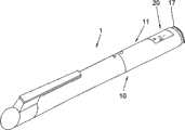
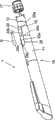
-图1示出根据本发明的注射装置的第一实施方式的透视图,在该的注射装置的前部上装有一盖罩,- Figure 1 shows a perspective view of a first embodiment of an injection device according to the invention, on the front of which a cover is mounted,
-图2示出本发明的注射装置的根据图1的第一实施方式的透视简图,- Figure 2 shows a schematic perspective view of the first embodiment of the injection device according to the invention according to Figure 1 ,
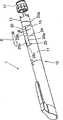
-图3示出根据本发明的注射装置的第二实施方式的透视简图,- Figure 3 shows a schematic perspective view of a second embodiment of the injection device according to the invention,
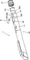
-图4示出根据本发明的注射装置的第三实施方式的透视简图,- Figure 4 shows a schematic perspective view of a third embodiment of the injection device according to the invention,
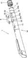
-图5示出根据本发明的注射装置的第四实施方式的透视简图,- Figure 5 shows a schematic perspective view of a fourth embodiment of an injection device according to the invention,
-图6示出根据本发明的注射装置的第五实施方式的透视简图,- Figure 6 shows a schematic perspective view of a fifth embodiment of an injection device according to the invention,
-图7示出根据本发明的注射装置的第六实施方式的透视简图,- Figure 7 shows a schematic perspective view of a sixth embodiment of an injection device according to the invention,
-图8示出根据本发明的注射装置的缺口和突起的表面部分的在一截面中可见的边缘线的走向的实施方式的视图,这里不考虑注射装置各部件、尤其是壳体的和指示套筒的筒形形状,- Figure 8 shows a view of an embodiment of the course of the edge lines visible in a section of the notch and the protruding surface part of the injection device according to the invention, without taking into account the components of the injection device, in particular the housing and the indication The cylindrical shape of the sleeve,
-图9示出根据图8中的视图的、根据本发明的注射装置的缺口和突起的表面部分的在一截面中可见的边缘线的走向的另一个实施方式的视图,- FIG. 9 shows a view according to the view in FIG. 8 of a further embodiment of the course of the edge lines visible in a section of the notches and raised surface parts of the injection device according to the invention,
-图10示出根据图8中的视图的、根据本发明的注射装置的缺口和突起的表面部分的在一截面中可见的边缘线的走向的另一个实施方式的视图,- FIG. 10 shows a view according to the view in FIG. 8 of another embodiment of the course of the edge lines visible in a section of the notches and raised surface parts of the injection device according to the invention,
-图11到17示出用于将插入套筒沿轴向锁定到壳体件上的锁定装置的不同实施方式。- Figures 11 to 17 show different embodiments of locking means for axially locking the insertion sleeve to the housing part.
具体实施方式Detailed ways
为了描述本发明,下面解释一下在说明书和权利要求书中使用的一些术语:In order to describe the present invention, some terms used in the specification and claims are explained below:
术语“近端”和“远端”用于限定根据本发明的注射装置的各部件的相对位置。这里,“近端”指的是各部件的在注射装置的预定应用中指向病人的一侧,即指向注射针头的一侧。相应地,“远端”意指各部件的与“近端”侧相反的一侧。The terms "proximal" and "distal" are used to define the relative positions of the various components of the injection device according to the invention. Here, "proximal end" refers to the side of each component which is directed towards the patient, ie towards the injection needle, in the intended application of the injection device. Accordingly, "distal" means the side of each component opposite the "proximal" side.
下面提到的用于容纳注射制剂的容器尤其可以是小筒或安瓿,该容器可以设计成不同的结构,例如圆筒形或拥有其他截面形状。The containers mentioned below for containing injection preparations can in particular be cartridges or ampoules, which can be of different designs, for example cylindrical or have other cross-sectional shapes.
本发明以用于容纳和注射医用注射制剂(溶液,悬浮液,乳状液)的注射装置为基础,该注射装置适合于以手动或自动、机械或机电的方式进行给药,并基于以下原理:借助一在小筒内沿轴向引导的活塞将注射制剂从小筒压入注射针头内。这种注射装置被设计成一次性装置或可重复使用的装置。The invention is based on an injection device for containing and injecting medical injectable preparations (solutions, suspensions, emulsions) suitable for administering them manually or automatically, mechanically or electromechanically, and based on the following principles: The injection preparation is pressed from the cartridge into the injection needle by means of a piston guided axially in the cartridge. Such injection devices are designed as disposable or reusable devices.
根据本发明的注射装置包括:An injection device according to the invention comprises:
-小筒模块,优选带有小筒支架/保持件/固定件、用于容纳注射制剂的小筒以及可能安装在小筒上的注射针头,注射针头安装在小筒或小筒支架的端部上,注射制剂可通过该注射针头被注射。- a cartridge module, preferably with a cartridge holder/holder/fixer, a cartridge for containing the injectable formulation and possibly an injection needle mounted on the cartridge, the injection needle being mounted at the end of the cartridge or the cartridge holder On, injection preparations can be injected through the injection needle.
-分配机构或驱动机构或传力机构,通过操作该分配机构或驱动机构或传力机构实现注射制剂的分配,以及- a dispensing mechanism or a drive mechanism or a force transmission mechanism, the operation of which dispensing mechanism or drive mechanism or force transmission mechanism realizes the dispensing of the injection preparation, and
-用于设定剂量的剂量设定机构,利用该剂量设定机构限定在操作分配机构时分配的注射制剂的量。- A dose setting mechanism for setting doses, with which the quantity of injectable formulation dispensed upon operation of the dispensing mechanism is defined.
在一个实施例中,根据本发明的用于分配药物的注射装置1包括一壳体,用以嵌装容纳注射制剂的容器。壳体可以包括前端或近端壳体件和后端或远端壳体件。或者,根据本发明的注射装置可包括一件式或一体式地制成的、或其它设计的壳体。In one embodiment, the
用于容纳注射制剂的小筒或容器包括:例如,一近端端部和一远端端部;具有内侧和外侧的、圆筒形或以其他方式延伸的纵壁;用于输出注射制剂的前端开口;以及后端开口,在该后端开口中可引入一可沿所述内侧移动的活塞。在活塞的起始位置、即容器完全装满的位置中,活塞优选被放置在容器的远端端部上。容器可以被直接插入在近端端部上具有开口的壳体内,或可能被插入到一前端壳体件内、进而插入壳体中。A cartridge or container for containing an injectable formulation includes, for example, a proximal end and a distal end; a cylindrical or otherwise extending longitudinal wall having an inner side and an outer side; a front opening; and a rear opening into which a piston movable along said inner side can be introduced. In the starting position of the piston, ie the fully filled position of the container, the piston is preferably placed on the distal end of the container. The container may be inserted directly into the housing having an opening at the proximal end, or may be inserted into a front housing part and thus into the housing.
如果注射装置被设计成可重复使用的装置,那么按规定在排空之后更换容器。If the injection device is designed as a reusable device, the container must be replaced after emptying.
因此,用于容纳注射制剂的容器可以被安装在容器接纳结构、或容器壳体、或具有近端端部和远端端部的容器支架中。然而替代地,容器支架也可以作壳体用。在此情况下,前端壳体件充当用于接纳容器的外部壳体的部件。注射针头(未示)可以安装或固定安装在容器的近端端部上,注射针头穿过外部壳体或容器壳体近端端部上的开口,和/或穿过壳体近端端部上的开口伸入容器内。Thus, a container for containing an injectable preparation may be mounted in a container receiving structure, or a container housing, or a container holder having a proximal end and a distal end. Alternatively, however, the vessel holder can also serve as housing. In this case, the front housing part serves as part of the outer housing for receiving the container. An injection needle (not shown) may be mounted or fixedly mounted on the proximal end of the container, the injection needle passing through an opening in the outer housing or container housing proximal end, and/or through the housing proximal end The upper opening extends into the container.
因此,根据本发明的、用于分配药物的注射装置特别包括:用于插入容纳注射制剂的容器的壳体和具有前端的近端端部和后端端部的容器,所述近端端部具有用于输出注射制剂的前端开口,用于插入壳体的近端内,所述后端端部具有后端开口,在该后端开口上插入有一位于起始位置的活塞,该活塞可借助于分配装置而沿着小筒的轴向移动。Thus, an injection device for dispensing a medicament according to the invention comprises in particular a housing for insertion of a container containing an injection preparation and the container having a front proximal end and a rear end, said proximal end It has a front opening for outputting injection preparations for insertion into the proximal end of the housing, said rear end has a rear opening on which a piston in a starting position is inserted, and the piston can be moved by means of The dispensing device moves along the axial direction of the small cylinder.
剂量设定机构包括:Dose setting mechanisms include:
-壳体件11,在两件式设计的壳体中,该壳体件优选为远端壳体件,其中接纳分配机构的至少一部分,-
-指示套筒13,该指示套筒能至少部分地插入远端壳体件中并能在该壳体件中转动,和- an indicating
-插入套筒15,该插入套筒能插入远端壳体件中,其中,插入套筒在插入状态下,以不能相对转动的方式,优选以不能相对转动并且轴向固定的方式,由壳体10接纳。- an
为此目的,插入套筒15的内径和指示套筒13的外径如此设置,使指示套筒13能被引入插入套筒15中。For this purpose, the inner diameter of the
分配机构与剂量设定机构相连接。剂量设定机构与分配机构机械式地共同作用。剂量设定机构可以是分配机构的内置组成部分,也可以是独立于分配机构的部件。The dispensing mechanism is connected with the dose setting mechanism. The dose setting mechanism cooperates mechanically with the dispensing mechanism. The dose setting mechanism can be an integral part of the dispensing mechanism or it can be a separate part of the dispensing mechanism.
分配机构分配注射制剂,分配的注射制剂的剂量由剂量设定机构设定。为了分配或施用注射制剂,分配机构可具有操作元件17,例如形式为注射钮,和借助活塞杆直接或间接与注射钮连接的活塞。The dispensing mechanism dispenses the injection preparation, and the dose of the dispensed injection preparation is set by the dose setting mechanism. For dispensing or administering an injection preparation, the dispensing mechanism can have an
剂量设定机构具有剂量设定功能,其中特别通过如下方式来进行剂量设定:在从活塞与指示套筒13无联接时,设定指示套筒13相对于远端壳体件的轴向位置。The dose setting mechanism has a dose setting function, wherein the dose setting is performed in particular by setting the axial position of the indicating
插入套筒可以具有内螺纹,在该内螺纹中能接纳指示套筒的相应的配合螺纹部,使指示套筒在相对插入套筒转动时沿轴向运动,从而借助设定的轴向位置来限定注射制剂的待分配剂量。The insertion sleeve can have an internal thread in which a corresponding mating thread of the indicating sleeve can be received, so that the indicating sleeve moves axially when it is rotated relative to the inserting sleeve, so that by means of a set axial position the The dose to be dispensed of the injectable formulation is limited.
可能的,插入套筒可与注射装置的其他部件、例如小筒模块相连接,特别是与这些部分相接合或相互锁定。Possibly, the insertion sleeve can be connected to other parts of the injection device, for example the cartridge module, in particular engage or interlock with these parts.
注射装置具有剂量施用功能,其中通过操作与活塞相连接的操作装置来分配借助剂量设定机构规定剂量的注射制剂。为此目的,在壳体或远端壳体件内、例如沿轴向引导分配机构的活塞杆,使活塞杆的轴向运动在运行中引起活塞朝向近端方向的轴向运动,从而实现注射制剂的分配。操作装置由注射装置的使用者、尤其是由病人或由医务人员或由控制装置操作,从而实现注射制剂的分配。操作和计量装置将操作元件的操作运动转换为活塞杆的限定的轴向运动,这种轴向运动引起活塞的限定的运动,从而通过病人的操作、通过注射针头分配限定量的注射制剂。The injection device has a dosing function, wherein a prescribed dose of injection preparation by means of a dose setting mechanism is dispensed by actuating an actuating device connected to the piston. For this purpose, the piston rod of the dispensing mechanism is guided in the housing or the distal housing part, for example, axially, so that an axial movement of the piston rod causes an axial movement of the piston in the proximal direction during operation, thereby enabling the injection Distribution of preparations. The actuating device is actuated by a user of the injection device, in particular by a patient or by medical personnel or by a control device, so that the injection preparation is dispensed. The operating and metering device converts the operating movement of the operating element into a defined axial movement of the piston rod, which causes a defined movement of the piston, thereby dispensing a defined amount of injectable preparation through the injection needle through the patient's operation.
插入套筒具有可以被引入远端壳体件中的圆筒形基体。为了使远端壳体件以不能相对转动的方式接纳插入套筒15,插入套筒15还包括在外表面上隆起或突起的表面部分或调节凸起20,该表面部分至少局部是可透视的或透明的。The insertion sleeve has a cylindrical base that can be introduced into the distal housing part. In order to allow the distal housing part to receive the
在本发明的另一种实施方式中,突起的表面部分20具有一个或多个标记(箭头、线条等等),所述标记适于简化剂量可读性,该剂量显示在穿过插入套筒的指示套筒上、并利用该指示套筒设定。这些标记可以通过例如印制或粘贴、以诸如印制、粘贴、切割、蚀刻等的机械或化学方式来施加。In another embodiment of the invention, the raised
壳体具有一在壳体的远端边缘处开口的缺口25,该缺口的形状使得,当沿插入方向E将插入套筒15引入远端壳体件11时,将隆起或突起的表面部分20从缺口的开口边缘26引入缺口内。The housing has a
这样设置隆起或突起的表面部分20的形状,使该表面部分以预定的精度在周向方向上匹配于缺口中,即缺口25的沿远端壳体件的轴向延伸的边缘25a、25b的相互面对的内棱相距一定的距离,该距离比隆起或突起的表面部分20在插入套筒的周向方向上的宽度B大或小一预定的量。或者,相应的缺口边缘25a、25b和隆起或突起的表面部分20可以形成间隙配合、过渡配合或过盈配合。The shape of the raised or protruding
使缺口和突起的表面部分20的尺寸相配合和为缺口设置有带开口的边缘26对注射装置的组装有利,尤其是因为能够更容易和/或以更高的精度进行组装,进而能够实现例如自动化程度更高的组装过程。Matching the size of the notch to the protruding
缺口25具有对接侧或近端边缘26,该对接侧或近端边缘26形成用于突起的表面部分20或缺口25内的连接边缘25c的轴向终端位置的止挡部。The
在插入套筒的一种实施方式中,在插入套筒的内侧上具有与指示套筒的可能存在的外螺纹共同作用的引导装置,从而根据指示套筒13的转动位置沿轴向调节指示套筒。通过过渡配合或过盈配合,可以根据指示套筒13相应的转动位置更精确地设定指示套筒13相对于壳体件11的轴向位置。这样便可以进一步提高由注射装置分配的设定剂量的精度。In one embodiment of the insert sleeve, on the inner side of the insert sleeve there is a guide which cooperates with a possibly present external thread of the indicator sleeve, so that the indicator sleeve is axially adjusted depending on the rotational position of the
此外,通过增加突起的表面部分20的厚度,例如通过将它配置成放大镜,可以提高剂量设定的可视性。这样,可以提高由使用者分配的设定剂量的精度。Furthermore, by increasing the thickness of the raised
隆起或突起的表面部分20、连同它在轴向方向上延伸的侧边20a、20b和它的近端边缘或对接边缘20c的形状,以及缺口25的形状,都可以不同:The shape of the raised or protruding
如图1和2所示,突起的表面部分的对接边缘20c和相应的缺口的对接边缘25c可以在周向方向上沿直线延伸。As shown in Figures 1 and 2, the
如图3所示,突起的表面部分20的对接边缘20c和相应的缺口的对接边缘25c,可由两条彼此成角度延伸、尤其是以尖角相交的线段形成。As shown in FIG. 3, the
如图4所示,突起的表面部分20的纵向边缘20a,20b和对接边缘20c、以及相应的缺口的纵向边缘25a、25b和对接边缘25c可设计成曲线,使得突起的表面部分20的轮廓和缺口局部形成卵形。As shown in Figure 4, the
如图5所示,在突起的表面部分20的轮廓的各可选构型中,在突起的表面部分的上侧上可形成另一凸起30,尤其是为了以另一凸起30的透明部分提供放大镜的效果。As shown in FIG. 5 , in each alternative configuration of the profile of the raised
如图6所示,突起的表面部分20的纵向边缘20a,20b、和相应的缺口25的纵向边缘25a、25b可以沿直线、尤其是相互平行地延伸,而突起的表面部分20的对接边缘20c、和相应的缺口25的对接边缘25c可设计成曲线。As shown in FIG. 6, the
如图7所示,尤其是在突起表面部分20的根据图6的轮廓构型中,在突起表面部分的上侧上可形成另一凸起30,尤其是为了以另一凸起30的透明部分提供放大镜的效果。As shown in FIG. 7 , in particular in the profile configuration according to FIG. 6 of the raised
根据本发明,可另外提供一锁定装置,以使插入套筒15沿轴向方向与壳体件11相锁定。这种锁定可以以不同的方式进行。例如,可在插入套筒15的外侧、即指向壳体件11的一侧上设置一锁定凸起,而在壳体件11的内表面的相应位置上设置一锁定槽或锁定凹部或锁定隙部,尤其是以锁定开口的形式,当插入套筒15被向壳体件11中推入其终端位置时,所述锁定凸起与锁定槽彼此锁定。According to the invention, a locking device can additionally be provided to lock the
可以用不同的方式设计缺口和突起部分的边缘构型。例如,缺口25和突起的表面部分20的纵向边缘和/或对接边缘可以设计成,使它们形锁合地相互接合。缺口25和突起的表面部分20各自的边缘面可以形成燕尾形引导结构或其他形式的引导结构。图8到10示出了突起的表面部分和缺口的纵向边缘的边缘面的构型,这些构型也可以替代或附加地形成在对接边缘的边缘面上。The edge configurations of the notches and protrusions can be designed in different ways. For example, the
图8示出了燕尾形导向结构,其中突起的表面部分的纵向边缘20a、20b的边缘面具有角形引导部,该角形引导部接合在缺口25的边缘面中相应的角形隙部中。图9示出了根据图8的燕尾形导向结构的变体,其中相反地,缺口25的边缘面具有角形引导部,该角形引导部接合在突起的表面部分20的纵向边缘20a、20b上中相应的角形隙部中。在根据图10的导向结构的实施方式中,在缺口的边缘面中的导向结构设计成一凹槽,而在突起的表面部分的边缘面中形成一相应的、接合到该凹槽中的配合结构。或者,也可以与之类似地使凹槽形成在缺口的边缘面中,而相应的配合部形成在突起的表面部分的边缘面中。FIG. 8 shows a dovetail guide in which the edge faces of the
远端壳体件可以沿着缺口边缘具有密封件,以更有效地使远端壳体件的内部与污物和/或湿气相隔绝。The distal housing member may have a seal along the edge of the notch to more effectively seal the interior of the distal housing member from dirt and/or moisture.
可以沿缺口25的边缘,即沿纵向边缘25a、25b和对接边缘设置密封件。替代或附加地,可以在插入套筒15的远端端部上和内表面上、优选沿着插入套筒15的远端端部的边缘,设置密封件。该密封件优选设计成围绕插入套筒15的外周延伸的密封件。该密封件可以具有环形形状、尤其是刷子形状。在上述可选方案中,密封件尤其可以围绕插入套筒15的远端边缘的开口延伸。Seals may be provided along the edges of the
插入套筒15上的上述密封件在插入套筒15的内表面和指示套筒13的外表面之间起作用,尤其是用于减少或防止颗粒或液体进入指示套筒13与插入套筒15之间,进而减少或防止壳体件11的内部被污染。The above-mentioned seal on the
替代或附加地,可以在插入套筒15的远端端部和外表面上、优选沿着插入套筒15的远端端部的边缘设置密封件,以防止壳体件11的内部被污染。附加或替代地,这种密封件也可以在突起的表面部分20的近端侧上、在插入套筒15的外侧的周向上延伸。Alternatively or additionally, a seal can be provided on the distal end and the outer surface of the
也可以在注射装置1上设置多个隆起或突起的表面部分20和多个相应的缺口25。It is also possible to provide a plurality of raised or protruding
图11到17示出了用于使插入套筒15沿轴向方向与壳体件11相锁定的锁定装置40的不同实施方式。11 to 17 show different embodiments of a
锁定装置40可以具有接纳结构49以及在壳体件11的凹部或隙部41内延伸的接片或舌片43,接片或舌片43的近端端部45与插入套筒15相连接,而其远端端部形成一自由端部47。自由端部47以锁定凸起的形式形成向外伸出的边缘区域51、51a、51b,该锁定凸起在插入套筒15被向壳体件11中推入其终端位置时接合在接纳结构49内。锁定凸起51、51a、51b可以由舌片43的向外、以角形延伸的伸出部和/或由在自由端部47上形成的锁定凸块51、51a、51b形成。The locking
如图11到15所示,与锁定装置40共同作用的接纳结构49可以设计成在壳体件11的内表面上的凹部。或者,接纳结构49可以设计成开口构型的隙部(图16和17)。As shown in FIGS. 11 to 15 , the receiving
在周向方向上,接纳结构49可以以与锁定凸起51、51a、51b的宽度一致和/或匹配的宽度延伸,以此宽度与插入套筒形成配合。优选提供这种配合,而不是设计有调节凸起的上述配合。接纳结构49可以在周向方向上延伸超过锁定凸起51、51a、51b的宽度,尤其可以设计成在壳体件11的内周面上延伸的凹部(图11和12)。In the circumferential direction, the receiving
自由端部47可以设计成被分割一次或多次的自由端部,以便可以提供一个或多个锁定凸起51、51a、51b,尤其是一个或多个锁定凸块。图16和17示出了锁定装置的一种实施方式,具有一被分割一次的自由端部,即具有两个形式为锁定凸块的锁定凸起51a、51b。相应地,接纳结构49具有两个凹部或隙部49a、49b。The
也可以在周向方向上提供多个舌片43,和多个相应的接纳结构,例如凹部或隙部。It is also possible to provide a plurality of
在具有多对舌片43和接纳结构的实施方式中,所述舌片和接纳结构对可以布置在相同的轴向位置上,或在轴向方向上相互偏置。In an embodiment with multiple pairs of
Claims (47)
Translated fromChineseApplications Claiming Priority (3)
| Application Number | Priority Date | Filing Date | Title |
|---|---|---|---|
| DE102007018696ADE102007018696A1 (en) | 2007-04-18 | 2007-04-18 | Injection device for dispensing a medicament |
| DE102007018696.9 | 2007-04-18 | ||
| PCT/EP2008/002787WO2008128645A1 (en) | 2007-04-18 | 2008-04-09 | Injection device for delivering a medication |
Publications (2)
| Publication Number | Publication Date |
|---|---|
| CN101663060A CN101663060A (en) | 2010-03-03 |
| CN101663060Btrue CN101663060B (en) | 2013-11-06 |
Family
ID=39672755
Family Applications (1)
| Application Number | Title | Priority Date | Filing Date |
|---|---|---|---|
| CN200880012589XAActiveCN101663060B (en) | 2007-04-18 | 2008-04-09 | Injection device for delivering a medication |
Country Status (18)
| Country | Link |
|---|---|
| US (1) | US10449299B2 (en) |
| EP (1) | EP2148710B1 (en) |
| JP (1) | JP5396381B2 (en) |
| KR (1) | KR101523237B1 (en) |
| CN (1) | CN101663060B (en) |
| AR (1) | AR066074A1 (en) |
| AU (1) | AU2008241089B2 (en) |
| BR (1) | BRPI0810032B8 (en) |
| CA (1) | CA2684351A1 (en) |
| DE (1) | DE102007018696A1 (en) |
| DK (1) | DK2148710T3 (en) |
| ES (1) | ES2758526T3 (en) |
| HU (1) | HUE046604T2 (en) |
| IL (1) | IL201500A (en) |
| MX (1) | MX2009010804A (en) |
| PL (1) | PL2148710T3 (en) |
| TW (1) | TWI487546B (en) |
| WO (1) | WO2008128645A1 (en) |
Families Citing this family (28)
| Publication number | Priority date | Publication date | Assignee | Title |
|---|---|---|---|---|
| US20070202186A1 (en) | 2006-02-22 | 2007-08-30 | Iscience Interventional Corporation | Apparatus and formulations for suprachoroidal drug delivery |
| US8197435B2 (en) | 2006-05-02 | 2012-06-12 | Emory University | Methods and devices for drug delivery to ocular tissue using microneedle |
| GB0918145D0 (en) | 2009-10-16 | 2009-12-02 | Owen Mumford Ltd | Injector apparatus |
| JP5996544B2 (en) | 2010-10-15 | 2016-09-21 | クリアサイド・バイオメディカル・インコーポレーテッドClearside Biomedical Incorporated | Eye access device |
| US9452265B2 (en) | 2011-03-18 | 2016-09-27 | Becton, Dickinson And Company | End of injection indicator for injection pen |
| US9993598B2 (en)* | 2011-10-06 | 2018-06-12 | Sanofi-Aventis Deutschland Gmbh | Display arrangement for a drug delivery device |
| EP2830685B1 (en)* | 2012-03-30 | 2017-05-31 | Tecpharma Licensing AG | Injection device with a dose display element displaceable relative to a housing. |
| MX360468B (en)* | 2012-04-05 | 2018-11-05 | Sanofi Aventis Deutschland | Pen -type injector with window element. |
| RU2724011C1 (en) | 2012-04-13 | 2020-06-18 | Бектон, Дикинсон Энд Компани | Automated device for injections |
| KR20210133321A (en) | 2012-11-08 | 2021-11-05 | 클리어사이드 바이오메디컬, 인코포레이드 | Methods and devices for the treatment of ocular disease in human subjects |
| CA2911290C (en) | 2013-05-03 | 2021-07-27 | Clearside Biomedical, Inc. | Apparatus and methods for ocular injection |
| EP3003454B1 (en) | 2013-06-03 | 2020-01-08 | Clearside Biomedical, Inc. | Apparatus for drug delivery using multiple reservoirs |
| US10668218B2 (en)* | 2013-08-29 | 2020-06-02 | Sanofi-Aventis Deutschland Gmbh | Housing and cap for an injection device made of an outer metal part and an inner plastic part |
| CA155281S (en)* | 2013-09-04 | 2015-02-10 | Sanofi Aventis Deutschland | Injection device with cap |
| CA155482S (en)* | 2013-09-20 | 2014-10-27 | Sanofi Aventis Deutschland | Injection device with cap |
| JP6543250B2 (en) | 2013-12-05 | 2019-07-10 | ノボ・ノルデイスク・エー/エス | Housing for medical injection device |
| RU2710491C2 (en) | 2014-06-20 | 2019-12-26 | Клиасайд Байомедикал, Инк. | Device for drug injection into ocular tissue and method for drug injection into ocular tissue |
| USD750223S1 (en) | 2014-10-14 | 2016-02-23 | Clearside Biomedical, Inc. | Medical injector for ocular injection |
| US10799644B2 (en) | 2015-06-01 | 2020-10-13 | Novo Nordisk A/S | Method for moulding a polymeric housing for a medical injection device |
| EP3413851B1 (en) | 2016-02-10 | 2023-09-27 | Clearside Biomedical, Inc. | Packaging |
| US9694145B1 (en)* | 2016-03-29 | 2017-07-04 | Joseph Onorato | Auto-injector systems and method for delivering cyst medication on demand |
| WO2017192565A1 (en) | 2016-05-02 | 2017-11-09 | Clearside Biomedical, Inc. | Systems and methods for ocular drug delivery |
| US10973681B2 (en) | 2016-08-12 | 2021-04-13 | Clearside Biomedical, Inc. | Devices and methods for adjusting the insertion depth of a needle for medicament delivery |
| US12090294B2 (en) | 2017-05-02 | 2024-09-17 | Georgia Tech Research Corporation | Targeted drug delivery methods using a microneedle |
| USD893715S1 (en) | 2018-11-06 | 2020-08-18 | Joseph Onorato | Measurement guide for a cyst, lesion or skin disorder |
| EP4596001A1 (en)* | 2024-02-02 | 2025-08-06 | Ypsomed AG | Magnifying lens for a drug delivery device |
| WO2025162755A1 (en)* | 2024-02-02 | 2025-08-07 | Ypsomed Ag | Magnifying lens for a drug delivery device |
| EP4596002A1 (en)* | 2024-02-02 | 2025-08-06 | Ypsomed AG | Magnifying lens for a drug delivery device |
Citations (4)
| Publication number | Priority date | Publication date | Assignee | Title |
|---|---|---|---|---|
| EP0688571A1 (en)* | 1994-06-22 | 1995-12-27 | Becton, Dickinson and Company | Quick connect medication delivery pen |
| CA2359375A1 (en)* | 1999-01-14 | 2000-07-20 | B D Medico S.A.R.L. | Injection device |
| CN1124861C (en)* | 1995-06-02 | 2003-10-22 | 诺沃挪第克公司 | Automatic withdrawal of piston rod |
| CN1243578C (en)* | 1998-01-30 | 2006-03-01 | 诺沃挪第克公司 | Syringe with a needle |
Family Cites Families (64)
| Publication number | Priority date | Publication date | Assignee | Title |
|---|---|---|---|---|
| US533575A (en) | 1895-02-05 | wilkens | ||
| US3973554A (en)* | 1975-04-24 | 1976-08-10 | The United States Of America As Represented By The Secretary Of The Department Of Health, Education And Welfare | Radiation safety shield for a syringe |
| DE3638984C3 (en)* | 1986-11-14 | 1993-11-18 | Haselmeier Wilhelm Fa | Injection device |
| DE3715340C2 (en) | 1987-05-08 | 1995-10-19 | Haselmeier Wilhelm Fa | Injection device |
| DE3715258C2 (en) | 1987-05-08 | 1996-10-31 | Haselmeier Wilhelm Fa | Injection device |
| GB8713810D0 (en) | 1987-06-12 | 1987-07-15 | Hypoguard Uk Ltd | Measured dose dispensing device |
| US5226895A (en) | 1989-06-05 | 1993-07-13 | Eli Lilly And Company | Multiple dose injection pen |
| GB9007113D0 (en) | 1990-03-29 | 1990-05-30 | Sams Bernard | Dispensing device |
| US5226896A (en) | 1990-04-04 | 1993-07-13 | Eli Lilly And Company | Dose indicating injection pen |
| AU641206B2 (en) | 1991-01-22 | 1993-09-16 | Eli Lilly And Company | Multiple dose injection pen |
| DK0525525T3 (en) | 1991-07-24 | 1995-10-02 | Medico Dev Investment Co | Injector |
| DK175491D0 (en) | 1991-10-18 | 1991-10-18 | Novo Nordisk As | APPARATUS |
| US5279585A (en) | 1992-02-04 | 1994-01-18 | Becton, Dickinson And Company | Medication delivery pen having improved dose delivery features |
| US5271527A (en) | 1992-04-02 | 1993-12-21 | Habley Medical Technology Corporation | Reusable pharmaceutical dispenser with full stroke indicator |
| US5300041A (en) | 1992-06-01 | 1994-04-05 | Habley Medical Technology Corporation | Dose setting and repeating syringe |
| US5391157A (en) | 1992-10-20 | 1995-02-21 | Eli Lilly And Company | End of dose indicator |
| US5378233A (en) | 1992-11-18 | 1995-01-03 | Habley Medical Technology Corporation | Selected dose pharmaceutical dispenser |
| US5320609A (en) | 1992-12-07 | 1994-06-14 | Habley Medical Technology Corporation | Automatic pharmaceutical dispensing syringe |
| FR2701211B1 (en) | 1993-02-08 | 1995-05-24 | Aguettant Lab | DOSING INSTRUMENT, ESPECIALLY INJECTION |
| US5383865A (en) | 1993-03-15 | 1995-01-24 | Eli Lilly And Company | Medication dispensing device |
| ZA941881B (en) | 1993-04-02 | 1995-09-18 | Lilly Co Eli | Manifold medication injection apparatus and method |
| US5582598A (en) | 1994-09-19 | 1996-12-10 | Becton Dickinson And Company | Medication delivery pen with variable increment dose scale |
| US5569214A (en)* | 1994-09-20 | 1996-10-29 | Becton Dickinson And Company | Dose setting knob adapter for medication delivery pen |
| JP3568959B2 (en) | 1995-03-07 | 2004-09-22 | イーライ・リリー・アンド・カンパニー | Reusable dosing device |
| AU1860697A (en) | 1995-09-08 | 1997-07-28 | Visionary Medical Products Corporation | Pen-type injector drive mechanism |
| US5688251A (en) | 1995-09-19 | 1997-11-18 | Becton Dickinson And Company | Cartridge loading and priming mechanism for a pen injector |
| US5674204A (en) | 1995-09-19 | 1997-10-07 | Becton Dickinson And Company | Medication delivery pen cap actuated dose delivery clutch |
| US5851079A (en) | 1996-10-25 | 1998-12-22 | The Procter & Gamble Company | Simplified undirectional twist-up dispensing device with incremental dosing |
| DE19730999C1 (en)* | 1997-07-18 | 1998-12-10 | Disetronic Licensing Ag | Injection pen dosing selected volume of fluid, especially insulin |
| US5921966A (en) | 1997-08-11 | 1999-07-13 | Becton Dickinson And Company | Medication delivery pen having an improved clutch assembly |
| US5961495A (en) | 1998-02-20 | 1999-10-05 | Becton, Dickinson And Company | Medication delivery pen having a priming mechanism |
| US6221053B1 (en) | 1998-02-20 | 2001-04-24 | Becton, Dickinson And Company | Multi-featured medication delivery pen |
| US6248095B1 (en) | 1998-02-23 | 2001-06-19 | Becton, Dickinson And Company | Low-cost medication delivery pen |
| GB9812472D0 (en)* | 1998-06-11 | 1998-08-05 | Owen Mumford Ltd | A dose setting device for medical injectors |
| CA2345439C (en)* | 1998-10-29 | 2005-08-09 | Minimed, Inc. | Compact pump drive system |
| US20050197626A1 (en)* | 1998-10-29 | 2005-09-08 | Medtronic Minimed Inc. | Fluid reservoir for use with an external infusion device |
| DE19900827C1 (en) | 1999-01-12 | 2000-08-17 | Disetronic Licensing Ag | Device for the dosed administration of an injectable product |
| DE19900792C1 (en) | 1999-01-12 | 2000-06-15 | Disetronic Licensing Ag | Injection unit forming part of e.g. pen-type self-injection syringe has continuous dosing stop in spiral form with constant pitch ensuring close fine control and accuracy in use |
| SE9901366D0 (en) | 1999-04-16 | 1999-04-16 | Pharmacia & Upjohn Ab | Injector device and method for its operation |
| AU6892100A (en) | 1999-08-05 | 2001-03-05 | Becton Dickinson & Company | Medication delivery pen |
| GB0007071D0 (en) | 2000-03-24 | 2000-05-17 | Sams Bernard | One-way clutch mechanisms and injector devices |
| US6663602B2 (en) | 2000-06-16 | 2003-12-16 | Novo Nordisk A/S | Injection device |
| FR2813533B1 (en)* | 2000-09-01 | 2003-03-07 | Lemer Pax | PROTECTIVE DEVICE FOR A SYRINGE, PARTICULARLY FOR A SYRINGE FOR INJECTING RADIOACTIVE PRODUCT (S) |
| CN1268405C (en) | 2000-10-09 | 2006-08-09 | 伊莱利利公司 | Pen device for administration of parathyroid hormone |
| US6899699B2 (en) | 2001-01-05 | 2005-05-31 | Novo Nordisk A/S | Automatic injection device with reset feature |
| DE10106368B4 (en)* | 2001-02-12 | 2006-02-02 | Tecpharma Licensing Ag | An adjustment barrier for a device for administering an adjustable dose of an injectable product |
| WO2002064092A2 (en)* | 2001-02-15 | 2002-08-22 | Kosan Biosciences, Inc. | Method for evaluating therapeutic efficacy |
| ES2365807T3 (en) | 2001-05-16 | 2011-10-11 | ELI LILLY & COMPANY | MEDICATION INJECTOR DEVICE WITH MOTOR ASSEMBLY THAT FACILITATES REARME. |
| JP4350525B2 (en) | 2002-03-18 | 2009-10-21 | イーライ リリー アンド カンパニー | Drug dispensing device with gear set giving mechanical advantages |
| US7454458B2 (en)* | 2002-06-24 | 2008-11-18 | Ntt Docomo, Inc. | Method and system for application load balancing |
| EP1545663B1 (en) | 2002-10-01 | 2006-08-30 | Becton Dickinson and Company | Medication delivery pen |
| GB0304822D0 (en) | 2003-03-03 | 2003-04-09 | Dca Internat Ltd | Improvements in and relating to a pen-type injector |
| GB0304823D0 (en) | 2003-03-03 | 2003-04-09 | Dca Internat Ltd | Improvements in and relating to a pen-type injector |
| US6932794B2 (en) | 2003-04-03 | 2005-08-23 | Becton, Dickinson And Company | Medication delivery pen |
| EP1541185A1 (en) | 2003-12-08 | 2005-06-15 | Novo Nordisk A/S | Automatic syringe with priming mechanism |
| DE102004004310A1 (en)* | 2004-01-28 | 2005-08-18 | Tecpharma Licensing Ag | Injection device with lockable dosing member |
| MX2007003682A (en)* | 2004-10-04 | 2007-08-07 | Sanofi Aventis Deutschland | Drive mechanism for a drug delivery device. |
| EP1642607A1 (en)* | 2004-10-04 | 2006-04-05 | Sanofi-Aventis Deutschland GmbH | Dose display mechanism for a drug delivery device |
| DE102004063644A1 (en) | 2004-12-31 | 2006-07-20 | Tecpharma Licensing Ag | Device for the dosed administration of a fluid product with torsion spring drive |
| US8257318B2 (en) | 2005-02-11 | 2012-09-04 | Novo Nordisk A/S | Injection device having a rotatable scale drum |
| US8062252B2 (en)* | 2005-02-18 | 2011-11-22 | Becton, Dickinson And Company | Safety shield system for a syringe |
| US20080269688A1 (en)* | 2005-12-08 | 2008-10-30 | Jose Colucci | Dose Indicating Assembly of a Pharmaceutical Injection Device |
| US8187233B2 (en) | 2008-05-02 | 2012-05-29 | Sanofi-Aventis Deutschland Gmbh | Medication delivery device |
| US8647309B2 (en) | 2008-05-02 | 2014-02-11 | Sanofi-Aventis Deutschland Gmbh | Medication delivery device |
- 2007
- 2007-04-18DEDE102007018696Apatent/DE102007018696A1/ennot_activeWithdrawn
- 2008
- 2008-04-09HUHUE08748875Apatent/HUE046604T2/enunknown
- 2008-04-09ESES08748875Tpatent/ES2758526T3/enactiveActive
- 2008-04-09WOPCT/EP2008/002787patent/WO2008128645A1/enactiveApplication Filing
- 2008-04-09DKDK08748875.5Tpatent/DK2148710T3/enactive
- 2008-04-09MXMX2009010804Apatent/MX2009010804A/enactiveIP Right Grant
- 2008-04-09AUAU2008241089Apatent/AU2008241089B2/enactiveActive
- 2008-04-09JPJP2010503381Apatent/JP5396381B2/enactiveActive
- 2008-04-09CACA002684351Apatent/CA2684351A1/ennot_activeAbandoned
- 2008-04-09EPEP08748875.5Apatent/EP2148710B1/enactiveActive
- 2008-04-09BRBRPI0810032Apatent/BRPI0810032B8/enactiveIP Right Grant
- 2008-04-09KRKR1020097021401Apatent/KR101523237B1/enactiveActive
- 2008-04-09CNCN200880012589XApatent/CN101663060B/enactiveActive
- 2008-04-09PLPL08748875Tpatent/PL2148710T3/enunknown
- 2008-04-16ARARP080101558Apatent/AR066074A1/enactiveIP Right Grant
- 2008-04-16TWTW097113720Apatent/TWI487546B/enactive
- 2009
- 2009-10-09USUS12/576,374patent/US10449299B2/enactiveActive
- 2009-10-13ILIL201500Apatent/IL201500A/enactiveIP Right Grant
Patent Citations (4)
| Publication number | Priority date | Publication date | Assignee | Title |
|---|---|---|---|---|
| EP0688571A1 (en)* | 1994-06-22 | 1995-12-27 | Becton, Dickinson and Company | Quick connect medication delivery pen |
| CN1124861C (en)* | 1995-06-02 | 2003-10-22 | 诺沃挪第克公司 | Automatic withdrawal of piston rod |
| CN1243578C (en)* | 1998-01-30 | 2006-03-01 | 诺沃挪第克公司 | Syringe with a needle |
| CA2359375A1 (en)* | 1999-01-14 | 2000-07-20 | B D Medico S.A.R.L. | Injection device |
Also Published As
| Publication number | Publication date |
|---|---|
| BRPI0810032B8 (en) | 2021-06-22 |
| CA2684351A1 (en) | 2008-10-30 |
| TW200909015A (en) | 2009-03-01 |
| AR066074A1 (en) | 2009-07-22 |
| MX2009010804A (en) | 2009-10-29 |
| EP2148710A1 (en) | 2010-02-03 |
| JP2010524526A (en) | 2010-07-22 |
| ES2758526T3 (en) | 2020-05-05 |
| US20100152667A1 (en) | 2010-06-17 |
| WO2008128645A1 (en) | 2008-10-30 |
| HK1141745A1 (en) | 2010-11-19 |
| BRPI0810032A2 (en) | 2014-10-14 |
| US10449299B2 (en) | 2019-10-22 |
| AU2008241089A1 (en) | 2008-10-30 |
| EP2148710B1 (en) | 2019-10-02 |
| HUE046604T2 (en) | 2020-03-30 |
| JP5396381B2 (en) | 2014-01-22 |
| CN101663060A (en) | 2010-03-03 |
| IL201500A (en) | 2012-12-31 |
| DK2148710T3 (en) | 2019-12-16 |
| IL201500A0 (en) | 2010-05-31 |
| KR20100015555A (en) | 2010-02-12 |
| DE102007018696A1 (en) | 2008-10-23 |
| KR101523237B1 (en) | 2015-05-28 |
| TWI487546B (en) | 2015-06-11 |
| PL2148710T3 (en) | 2020-03-31 |
| AU2008241089B2 (en) | 2013-02-28 |
| BRPI0810032B1 (en) | 2019-02-12 |
Similar Documents
| Publication | Publication Date | Title |
|---|---|---|
| CN101663060B (en) | Injection device for delivering a medication | |
| KR100877793B1 (en) | Dosing tool with dosage control device | |
| US9457150B2 (en) | Biasing mechanism for a drug delivery device | |
| US8585656B2 (en) | Dose setting mechanism for priming a drug delivery device | |
| KR100877795B1 (en) | Storage module with piston rod | |
| KR100574630B1 (en) | Injection syringe | |
| JP3042710B2 (en) | Pencil syringe assembly | |
| AU2003243922B2 (en) | A needle mounting system and a method for mounting a needle assembly | |
| KR100877796B1 (en) | Locking device for connecting housing sections of an administration appliance | |
| US20180207364A1 (en) | Dose Setting Mechanism for Priming a Drug Delivery Device | |
| US9125994B2 (en) | Drug delivery device with dose dial sleeve rotational stop | |
| HUP0102525A2 (en) | A medical delivery device and a cartridge assembly for use in the same | |
| AU2007207309A1 (en) | Injection device with secured dosing button | |
| KR20040030901A (en) | Connection of housing sections of an administration device for dosed administration of a distributable product | |
| JP2004049726A (en) | Syringe | |
| JP2018516674A (en) | Housing for medical injection device | |
| JP2021100588A (en) | Housing for mounting container on injection pen, assembly for forming injection agent storage tank for injection pen and injection pen including assembly | |
| HK1141745B (en) | Injection device for dispensing a medicament | |
| JP2016521167A (en) | Drug administration device and assembly method thereof | |
| US20220323694A1 (en) | Keyed connectors | |
| CN117425510A (en) | Drug delivery device | |
| CZ20004892A3 (en) | Drug delivery device and cartridge assembly for this device |
Legal Events
| Date | Code | Title | Description |
|---|---|---|---|
| C06 | Publication | ||
| PB01 | Publication | ||
| C10 | Entry into substantive examination | ||
| SE01 | Entry into force of request for substantive examination | ||
| REG | Reference to a national code | Ref country code:HK Ref legal event code:DE Ref document number:1141745 Country of ref document:HK | |
| C14 | Grant of patent or utility model | ||
| GR01 | Patent grant | ||
| REG | Reference to a national code | Ref country code:HK Ref legal event code:GR Ref document number:1141745 Country of ref document:HK |