CN101662906B - Electronic device - Google Patents
Electronic deviceDownload PDFInfo
- Publication number
- CN101662906B CN101662906BCN2008103041987ACN200810304198ACN101662906BCN 101662906 BCN101662906 BCN 101662906BCN 2008103041987 ACN2008103041987 ACN 2008103041987ACN 200810304198 ACN200810304198 ACN 200810304198ACN 101662906 BCN101662906 BCN 101662906B
- Authority
- CN
- China
- Prior art keywords
- elastic member
- panel
- rotating body
- electronic device
- rotating
- Prior art date
- Legal status (The legal status is an assumption and is not a legal conclusion. Google has not performed a legal analysis and makes no representation as to the accuracy of the status listed.)
- Expired - Fee Related
Links
Images


Classifications
- G—PHYSICS
- G06—COMPUTING OR CALCULATING; COUNTING
- G06F—ELECTRIC DIGITAL DATA PROCESSING
- G06F1/00—Details not covered by groups G06F3/00 - G06F13/00 and G06F21/00
- G06F1/16—Constructional details or arrangements
- G06F1/1613—Constructional details or arrangements for portable computers
- G06F1/1633—Constructional details or arrangements of portable computers not specific to the type of enclosures covered by groups G06F1/1615 - G06F1/1626
- G06F1/1675—Miscellaneous details related to the relative movement between the different enclosures or enclosure parts
- G06F1/1679—Miscellaneous details related to the relative movement between the different enclosures or enclosure parts for locking or maintaining the movable parts of the enclosure in a fixed position, e.g. latching mechanism at the edge of the display in a laptop or for the screen protective cover of a PDA
- G—PHYSICS
- G06—COMPUTING OR CALCULATING; COUNTING
- G06F—ELECTRIC DIGITAL DATA PROCESSING
- G06F1/00—Details not covered by groups G06F3/00 - G06F13/00 and G06F21/00
- G06F1/16—Constructional details or arrangements
- G06F1/1613—Constructional details or arrangements for portable computers
- G06F1/1615—Constructional details or arrangements for portable computers with several enclosures having relative motions, each enclosure supporting at least one I/O or computing function
- G06F1/1616—Constructional details or arrangements for portable computers with several enclosures having relative motions, each enclosure supporting at least one I/O or computing function with folding flat displays, e.g. laptop computers or notebooks having a clamshell configuration, with body parts pivoting to an open position around an axis parallel to the plane they define in closed position
- Y—GENERAL TAGGING OF NEW TECHNOLOGICAL DEVELOPMENTS; GENERAL TAGGING OF CROSS-SECTIONAL TECHNOLOGIES SPANNING OVER SEVERAL SECTIONS OF THE IPC; TECHNICAL SUBJECTS COVERED BY FORMER USPC CROSS-REFERENCE ART COLLECTIONS [XRACs] AND DIGESTS
- Y10—TECHNICAL SUBJECTS COVERED BY FORMER USPC
- Y10S—TECHNICAL SUBJECTS COVERED BY FORMER USPC CROSS-REFERENCE ART COLLECTIONS [XRACs] AND DIGESTS
- Y10S248/00—Supports
- Y10S248/917—Video display screen support
Landscapes
- Engineering & Computer Science (AREA)
- Computer Hardware Design (AREA)
- Theoretical Computer Science (AREA)
- Physics & Mathematics (AREA)
- Human Computer Interaction (AREA)
- General Engineering & Computer Science (AREA)
- General Physics & Mathematics (AREA)
- Mathematical Physics (AREA)
- Casings For Electric Apparatus (AREA)
Abstract
Translated fromChinese
Description
Translated fromChinese技术领域technical field
本发明涉及一种电子装置及其卡扣结构。The invention relates to an electronic device and its buckle structure.
背景技术Background technique
便携式电子装置,如笔记本电脑因为便于携带受到众多使用者的青睐,当笔记本电脑不使用时,为了避免在移动过程中对电脑造成损害,通常会将显示器通过扣合结构扣合于主机上以保护显示器及主机。Portable electronic devices, such as notebook computers, are favored by many users because they are easy to carry. When the notebook computer is not in use, in order to avoid damage to the computer during the movement, the display is usually buckled on the host computer through a buckle structure to protect it. display and host.
一种电子装置包括主机和显示器。该电子装置的扣合结构包括设置在主机上的卡扣组件和设置在显示器上的第一卡合部。卡扣组件包括在主机内部设置的弹性元件、与弹性元件固定连接的按钮以及在主机上与弹性元件和按钮对应的地方开设的收容孔,第一卡合部可从收容孔进入主机内部。弹性元件包括弧形的片状底座以及从底座两边缘延伸出的两弹片,两弹片之间形成一容置空间,按钮通过连接杆连接于弹性元件上。当显示器扣合于主机上时,在外力作用下第一卡合部向容置空间运动,使其中一个弹片绕底座转动,第一卡合部进入容置空间后抵持住底座,弹片回复至初始状态并将第一卡合部卡持于容置空间内。当使用电子装置时,可以按压按钮使之前转动的弹片再次绕底座转动,片状底座给第一卡合部一个向上的力后第一卡合部便可以脱离容置空间,从而可将显示器相对主机掀开。在第一卡合部与弹性元件扣合以及分离的过程中,弹片与第一卡合部之间均会互相抵持,因此第一卡合部与弹片之间的摩擦较大,需要较大的外力。此外,第一卡合部的宽度与弹片之间的宽度 会互相限制,如果第一卡合部很窄,则固定效果不佳;如果加宽则要求弹片旋转的角度加大,弹片容易产生弹性疲劳。An electronic device includes a host and a display. The fastening structure of the electronic device includes a buckle component arranged on the host and a first fastening part arranged on the display. The buckle assembly includes an elastic element arranged inside the host, a button fixedly connected with the elastic element, and a receiving hole opened on the host corresponding to the elastic element and the button, and the first engaging part can enter the inside of the host through the receiving hole. The elastic element includes an arc-shaped sheet base and two elastic pieces extending from both edges of the base. An accommodating space is formed between the two elastic pieces, and the button is connected to the elastic element through a connecting rod. When the display is fastened to the host, the first engaging part moves toward the accommodation space under the action of an external force, so that one of the shrapnels rotates around the base, the first engaging part enters the accommodation space and holds the base, and the shrapnel returns to It is in the initial state and the first locking part is locked in the accommodating space. When using an electronic device, you can press the button to make the previously rotated shrapnel rotate around the base again, and the flake base will give the first engaging part an upward force, and then the first engaging part can be separated from the accommodating space, so that the display can be relatively The host is opened. In the process of fastening and separating the first engaging part and the elastic element, the elastic piece and the first engaging part will resist each other, so the friction between the first engaging part and the elastic piece is relatively large, requiring a large external force. In addition, the width of the first engaging part and the width between the shrapnel will limit each other. If the first engaging part is narrow, the fixing effect will not be good; if it is widened, the angle of rotation of the shrapnel is required to increase, and the shrapnel is prone to elasticity. fatigue.
发明内容Contents of the invention
鉴于上述状况,有必要提供一种卡扣结构具较佳耐用性的电子装置及其卡扣结构。In view of the above situation, it is necessary to provide an electronic device with better durability of the buckle structure and its buckle structure.
一种电子装置,包括第一机体和第二机体,第一机体可旋转地连接于第二机体,第一机体上设置有第一卡合部,第二机体内部设置有卡扣组件,该卡扣组件包括可旋转连接于第二机体上的旋转体,旋转体上开设有第二卡合部,旋转体可旋转以使第一卡合部与第二卡合部在卡持与脱离的位置间切换,第二机体包括相对的第一面板和第二面板,以及连接第一面板和第二面板的侧壁,第一面板上开设有贯穿第一面板的容纳孔,侧壁上对应开设有贯穿侧壁的收容孔,卡扣组件还包括第一弹性件、第二弹性件和转轴,第一弹性件和第二弹性件均连接于旋转体和第二面板之间,转轴贯穿旋转体并固定连接于第二机体上,第一弹性件为压缩弹簧,第二弹性件为拉伸弹簧。An electronic device, comprising a first body and a second body, the first body is rotatably connected to the second body, the first body is provided with a first engaging portion, and the second body is provided with a buckle assembly inside, the card The clasp assembly includes a rotatable body that is rotatably connected to the second body. The rotatable body is provided with a second engaging portion. The rotatable body can rotate so that the first engaging portion and the second engaging portion are in the position of engaging and disengaging. The second body includes a first panel and a second panel opposite to each other, and a side wall connecting the first panel and the second panel. The first panel is provided with an accommodating hole through the first panel, and the side wall is correspondingly provided with Through the receiving hole of the side wall, the buckle assembly also includes a first elastic member, a second elastic member and a rotating shaft, the first elastic member and the second elastic member are connected between the rotating body and the second panel, the rotating shaft passes through the rotating body and It is fixedly connected to the second machine body, the first elastic part is a compression spring, and the second elastic part is a tension spring.
上述电子装置和卡扣结构中的旋转体在旋转至不同位置时,第二卡合部开口朝向不同,因此与第一卡合部的接触状态也不相同,借此来实现旋转体对第一卡合部的卡持和释放。第一卡合部和旋转体之间不存在弹性形变,可以避免长时间使用后因弹性疲劳而出现卡持不牢的情况。When the rotator in the above-mentioned electronic device and the buckle structure rotates to different positions, the opening orientation of the second engaging part is different, so the contact state with the first engaging part is also different. Engagement and release of the engaging part. There is no elastic deformation between the first engaging part and the rotating body, which can avoid the situation of loose clamping due to elastic fatigue after long-term use.
附图说明Description of drawings
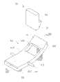
图1是本发明实施例的电子装置结构示意图。FIG. 1 is a schematic structural diagram of an electronic device according to an embodiment of the present invention.
图2是图1所示电子装置的第一卡合部和卡扣组件的结构示意 图。Fig. 2 is a schematic structural view of the first engaging portion and the buckle assembly of the electronic device shown in Fig. 1 .
图3是图2所示第一卡合部和卡扣组件沿III-III的剖视图。Fig. 3 is a sectional view along III-III of the first engaging portion and the buckle assembly shown in Fig. 2 .
图4是图2所示第一卡合部和卡扣组件处于扣合状态时的剖面示意图。Fig. 4 is a schematic cross-sectional view of the first engaging portion and the buckle assembly shown in Fig. 2 when they are in a fastened state.
图5是图2所示第一卡合部和卡扣组件处于分离状态时的剖面示意图。FIG. 5 is a schematic cross-sectional view of the first engaging portion and the buckle assembly shown in FIG. 2 in a separated state.
具体实施方式Detailed ways
本发明的电子装置可以是笔记本电脑、便携式DVD(DigitalVideo Disc,数字视频光盘)播放器等。下面以笔记本电脑为例并结合附图对本发明实施例提供的电子装置及其卡扣结构作进一步详细说明。The electronic device of the present invention may be a notebook computer, a portable DVD (Digital Video Disc, digital video disc) player, etc. The electronic device and its buckle structure provided by the embodiments of the present invention will be further described below in detail by taking a notebook computer as an example and referring to the accompanying drawings.
请参阅图1,该笔记本电脑包括第一机体10、第二机体20和设于第一机体10上的第一卡合部30和第二机体20上的卡扣组件40。第一机体10可旋转地连接于第二机体20,本实施例中,第一机体10为盖体,第二机体20为主体。Referring to FIG. 1 , the notebook computer includes a
第一机体10大致为长方体,可相对第二机体20旋转。The
第二机体20大致为长方体,具有第一面板21、第二面板23以及侧壁25。第一面板21和第二面板23相对设置,侧壁25自第二面板23一边缘垂直延伸并与第一面板21一边缘相连接。第一面板21远离第一机体10与第二机体20连接端的一侧开设有矩形容纳孔211,侧壁25上对应开设有矩形收容孔251。The
请同时参阅图2,第一卡合部30为卡钩,包括钩部31和本体33。钩部31由该本体33一端延伸形成。该钩部31大致为四棱台形,该本体33为长方体形。Please also refer to FIG. 2 , the first
卡扣组件40固定于第二机体20内,且位于容纳孔211的下方, 卡扣组件40包括旋转体41、第一弹性件43、第二弹性件45以及转轴47。The
旋转体41大致为一弧形板,具有光滑连接的弧面段411和平面段413。旋转体41的弧面段413上设有第二卡合部415,平面段413横向开设有装配孔417。该弧面段413自靠近卡槽415的部位向远离平面段413的方向延伸有一个固定部419(如图3所示)。本实施例中,第二卡合部415为在弧面段413纵向开设的通孔。The rotating
第一弹性件43为柱状螺旋压缩弹簧,一端与固定部419相抵,一端固定于第二面板23上。The first
第二弹性件45为柱状螺旋拉伸弹簧,一端与旋转体41的平面段413相抵,一端固定于第二面板23上。The second
转轴47穿过旋转体41的装配孔417,两端固定于第二机体20内部两个相对的固定板(图未示)上。The rotating
旋转体41通过转轴47固定于第二机体20内,且平面段413部分可穿过侧壁25上的容纳孔251并凸出于侧壁25。旋转体41可绕转轴47旋转,容纳孔251的上下侧壁可以限制旋转体41的旋转角度。第一弹性件43自然状态时的长度大于第二弹性件45自然状态时的长度,因此,当第一弹性件43和第二弹性件45处于自然状态时,弧面段411高于平面段413,第二卡合部415开口朝向与第一卡合部30之间有一定的角度。The rotating
请一并参阅图1至图4,当扣合第一机体10和第二机体20时,第一卡合部30首先穿过第二机体20的第一面板21上的容纳孔211进入第二机体20内,因为第二卡合部415开口与第一卡合部30之间有一定的角度,钩部31便与第二卡合部415的一个边缘相抵持。第一卡合部30继续向下运动,第一卡合部30便会给旋转体41施加压力,使旋转体41压缩第一弹性件43,同时旋转体41绕转轴 47旋转并拉伸第二弹性件45,当旋转体41旋转至第二卡合部415的开口正对第一卡合部30的钩部31时,钩部31进入第二卡合部415内。当钩部31进入第二卡合部415后,对旋转体41的压力消失,在第一弹性件43和第二弹性件45的弹性回复力下,旋转体41绕转轴47反向旋转并回复至初始状态,此时,钩部31与第二卡合部415的内壁相抵持,卡持于第二卡合部415内,第一机体10和第二机体20扣合。Please refer to FIG. 1 to FIG. 4 together. When fastening the
请一并参阅图1、图2和图5,当需要掀开第一机体10时,可向上拨动旋转体41凸出于侧壁25的部分,以拉伸第二弹性件45,并同时压缩第一弹性件43,当旋转体41的第二卡合部415的开口大致正对第一卡合部30的钩部31时,第二卡合部415对钩部31的卡持力消失。此时给第一机体10一个向上的力,第一卡合部30便脱离第二卡合部415,接着从容纳孔211离开第二机体20,第一机体10被掀开。Please refer to Fig. 1, Fig. 2 and Fig. 5 together. When the
旋转体41在旋转至不同位置时,第二卡合部415开口的朝向不同,因此与第一卡合部30的接触状态也不相同,借此来实现旋转体41对第一卡合部30的卡持和释放,第一卡合部30和旋转体41之间不存在弹性形变,可以避免长时间使用后因弹性疲劳而出现卡持不牢的情况。When the
可以理解,第一机体10和第二机体20也可以互换,即第一机体10为主体,第二机体20为盖体。It can be understood that the
另外,本领域技术人员还可在本发明精神内做其它变化,当然,这些依据本发明精神所做的变化,都应包含在本发明所要求保护的范围内。In addition, those skilled in the art can also make other changes within the spirit of the present invention. Of course, these changes made according to the spirit of the present invention should be included in the scope of protection claimed by the present invention.
Claims (4)
Translated fromChinesePriority Applications (2)
| Application Number | Priority Date | Filing Date | Title |
|---|---|---|---|
| CN2008103041987ACN101662906B (en) | 2008-08-26 | 2008-08-26 | Electronic device |
| US12/330,579US7876567B2 (en) | 2008-08-26 | 2008-12-09 | Foldable electronic device and latch mechanism applied in the foldable electronic device |
Applications Claiming Priority (1)
| Application Number | Priority Date | Filing Date | Title |
|---|---|---|---|
| CN2008103041987ACN101662906B (en) | 2008-08-26 | 2008-08-26 | Electronic device |
Publications (2)
| Publication Number | Publication Date |
|---|---|
| CN101662906A CN101662906A (en) | 2010-03-03 |
| CN101662906Btrue CN101662906B (en) | 2011-08-31 |
Family
ID=41725158
Family Applications (1)
| Application Number | Title | Priority Date | Filing Date |
|---|---|---|---|
| CN2008103041987AExpired - Fee RelatedCN101662906B (en) | 2008-08-26 | 2008-08-26 | Electronic device |
Country Status (2)
| Country | Link |
|---|---|
| US (1) | US7876567B2 (en) |
| CN (1) | CN101662906B (en) |
Families Citing this family (7)
| Publication number | Priority date | Publication date | Assignee | Title |
|---|---|---|---|---|
| CN101730425B (en)* | 2008-10-13 | 2013-03-13 | 深圳富泰宏精密工业有限公司 | Capped lock structure |
| CN102063157A (en)* | 2009-11-18 | 2011-05-18 | 鸿富锦精密工业(深圳)有限公司 | Computer shell locking device |
| CN105256506B (en)* | 2010-03-01 | 2017-12-15 | 伊利诺斯工具制品有限公司 | Hood lock with the anti-tamper feature of magnetic |
| JP5506540B2 (en) | 2010-05-24 | 2014-05-28 | パナソニック株式会社 | Electronics |
| JP6735454B2 (en)* | 2015-11-06 | 2020-08-05 | パナソニックIpマネジメント株式会社 | Electronic equipment and latch mechanism |
| CN107575454A (en)* | 2017-09-19 | 2018-01-12 | 珠海格力电器股份有限公司 | Buckle structure and buckle connecting device |
| CN115046092B (en)* | 2022-06-15 | 2023-12-29 | 杭州萤石软件有限公司 | Electronic device |
Citations (2)
| Publication number | Priority date | Publication date | Assignee | Title |
|---|---|---|---|---|
| US6659516B2 (en)* | 2001-01-05 | 2003-12-09 | Apple Computer, Inc. | Locking system for a portable computer |
| CN2696026Y (en)* | 2004-05-20 | 2005-04-27 | 无敌科技股份有限公司 | Snap structure of electronic data processor |
Family Cites Families (10)
| Publication number | Priority date | Publication date | Assignee | Title |
|---|---|---|---|---|
| KR19990000303A (en) | 1997-06-04 | 1999-01-15 | 윤종용 | Switchgear of a notebook computer |
| US6848662B2 (en)* | 2002-01-24 | 2005-02-01 | Zih Corp. | Secure latching system |
| TW551788U (en)* | 2002-11-22 | 2003-09-01 | Compal Electronics Inc | Easy-to-open buckling device |
| US6930887B2 (en)* | 2003-06-11 | 2005-08-16 | Dell Products L.P. | Method and system for coupling a chassis to a rail |
| KR100745800B1 (en) | 2004-04-27 | 2007-08-02 | 엘지전자 주식회사 | Latches for Portable Computers |
| TWI234060B (en) | 2004-04-30 | 2005-06-11 | Inventec Besta Co Ltd | Retainer |
| TWM270634U (en) | 2004-08-19 | 2005-07-11 | Compal Electronics Inc | Engagement module of portable computer |
| TWM306675U (en) | 2006-03-15 | 2007-02-21 | Inventec Corp | Two-way lock joint structure of tablet personal computer |
| US7385809B2 (en)* | 2006-05-05 | 2008-06-10 | Panasonic Automotive Systems Company Of America, Division Of Panasonic Corporation Of North America | Push release latch for a flip-down display device |
| TWM314361U (en) | 2007-01-19 | 2007-06-21 | Quanta Comp Inc | Latch design of a notebook computer |
- 2008
- 2008-08-26CNCN2008103041987Apatent/CN101662906B/ennot_activeExpired - Fee Related
- 2008-12-09USUS12/330,579patent/US7876567B2/ennot_activeExpired - Fee Related
Patent Citations (2)
| Publication number | Priority date | Publication date | Assignee | Title |
|---|---|---|---|---|
| US6659516B2 (en)* | 2001-01-05 | 2003-12-09 | Apple Computer, Inc. | Locking system for a portable computer |
| CN2696026Y (en)* | 2004-05-20 | 2005-04-27 | 无敌科技股份有限公司 | Snap structure of electronic data processor |
Also Published As
| Publication number | Publication date |
|---|---|
| US7876567B2 (en) | 2011-01-25 |
| US20100053886A1 (en) | 2010-03-04 |
| CN101662906A (en) | 2010-03-03 |
Similar Documents
| Publication | Publication Date | Title |
|---|---|---|
| CN101662906B (en) | Electronic device | |
| CN101959379B (en) | Electronic equipment and blocking device thereof | |
| US8435054B2 (en) | Electronic device with pivotal cover | |
| US9237666B2 (en) | Folding electronic device with retracting locking mechanism | |
| TWI437948B (en) | Electronic device and moving mechanism thereof | |
| US9277035B2 (en) | Releasing mechanism for housing of portable electronic device | |
| CN101636053B (en) | Electronic equipment | |
| TWI678141B (en) | Electronic device and battery locking mechanism | |
| US8964381B2 (en) | Electronic device locking/unlocking mechanism | |
| CN101636052B (en) | Electronic equipment | |
| CN101625578A (en) | Electronic equipment | |
| CN101472412A (en) | Cover-turning type electronic device casing | |
| US20140021727A1 (en) | Opening-aid locking/unlocking mechanism of electronic device | |
| CN103313565B (en) | Snap mechanism | |
| US20170340079A1 (en) | Receiving device | |
| CN101472411A (en) | Cover-turning type electronic device casing | |
| CN101626669B (en) | Electronic equipment | |
| TW201349982A (en) | Electronic device with a cover capable of being hooked to a main body | |
| CN101728711A (en) | Portable electronic device | |
| CN101272668A (en) | Electronic device and protective cover thereof | |
| TWI578878B (en) | Electronic apparatus and device fixing structure thereof | |
| US9077788B2 (en) | Electronic apparatus | |
| TWI649020B (en) | Electronic device and support structure thereof | |
| CN101996668B (en) | CD driver baffle plate combination | |
| CN101938534B (en) | Electronic device and its moving mechanism |
Legal Events
| Date | Code | Title | Description |
|---|---|---|---|
| C06 | Publication | ||
| PB01 | Publication | ||
| C10 | Entry into substantive examination | ||
| SE01 | Entry into force of request for substantive examination | ||
| C14 | Grant of patent or utility model | ||
| GR01 | Patent grant | ||
| ASS | Succession or assignment of patent right | Owner name:BEIJING ZHONGCAI WYSE EDUCATION TECHNOLOGY CO., LT Free format text:FORMER OWNER: HONGFUJIN PRECISE INDUSTRY (SHENZHEN) CO., LTD. Effective date:20141121 Free format text:FORMER OWNER: HONGFUJIN PRECISE INDUSTRY CO., LTD. Effective date:20141121 Owner name:NANTONG JIUHUAN INDUSTRIAL CO., LTD. Free format text:FORMER OWNER: BEIJING ZHONGCAI WYSE EDUCATION TECHNOLOGY CO., LTD. Effective date:20141121 | |
| C41 | Transfer of patent application or patent right or utility model | ||
| COR | Change of bibliographic data | Free format text:CORRECT: ADDRESS; FROM: 100083 HAIDIAN, BEIJING TO: 226363 NANTONG, JIANGSU PROVINCE Free format text:CORRECT: ADDRESS; FROM: 518109 SHENZHEN, GUANGDONG PROVINCE TO: 100083 HAIDIAN, BEIJING | |
| TR01 | Transfer of patent right | Effective date of registration:20141121 Address after:226363, Jiangsu, Nantong province Tongzhou District Liu Zhen industrial concentration area (West) Patentee after:Nantong nine ring Industry Co.,Ltd. Address before:100083 Beijing Haidian District Zhongguancun Road No. 18 smartfortune International Building B706 Patentee before:Beijing Zhongcai Wyse Education Technology Co.,Ltd. Effective date of registration:20141121 Address after:100083 Beijing Haidian District Zhongguancun Road No. 18 smartfortune International Building B706 Patentee after:Beijing Zhongcai Wyse Education Technology Co.,Ltd. Address before:518109 Guangdong city of Shenzhen province Baoan District Longhua Town Industrial Zone tabulaeformis tenth East Ring Road No. 2 two Patentee before:HONG FU JIN PRECISION INDUSTRY (SHENZHEN) Co.,Ltd. Patentee before:HON HAI PRECISION INDUSTRY Co.,Ltd. | |
| CF01 | Termination of patent right due to non-payment of annual fee | ||
| CF01 | Termination of patent right due to non-payment of annual fee | Granted publication date:20110831 Termination date:20170826 |