CN101661033A - Test strip, biochemical sensing system and measuring device - Google Patents
Test strip, biochemical sensing system and measuring deviceDownload PDFInfo
- Publication number
- CN101661033A CN101661033ACN200810214831ACN200810214831ACN101661033ACN 101661033 ACN101661033 ACN 101661033ACN 200810214831 ACN200810214831 ACN 200810214831ACN 200810214831 ACN200810214831 ACN 200810214831ACN 101661033 ACN101661033 ACN 101661033A
- Authority
- CN
- China
- Prior art keywords
- test piece
- composed component
- detection test
- insulated substrate
- identification unit
- Prior art date
- Legal status (The legal status is an assumption and is not a legal conclusion. Google has not performed a legal analysis and makes no representation as to the accuracy of the status listed.)
- Granted
Links
- 238000012360testing methodMethods0.000titleclaimsabstractdescription86
- 238000001514detection methodMethods0.000claimsabstractdescription84
- 239000000758substrateSubstances0.000claimsabstractdescription51
- 238000006243chemical reactionMethods0.000claimsdescription24
- 239000003292glueSubstances0.000claimsdescription10
- 239000000463materialSubstances0.000claimsdescription9
- OKTJSMMVPCPJKN-UHFFFAOYSA-NCarbonChemical compound[C]OKTJSMMVPCPJKN-UHFFFAOYSA-N0.000claimsdescription7
- BQCADISMDOOEFD-UHFFFAOYSA-NSilverChemical compound[Ag]BQCADISMDOOEFD-UHFFFAOYSA-N0.000claimsdescription6
- 229910052709silverInorganic materials0.000claimsdescription6
- 239000004332silverSubstances0.000claimsdescription6
- 229910052799carbonInorganic materials0.000claimsdescription3
- PCHJSUWPFVWCPO-UHFFFAOYSA-NgoldChemical compound[Au]PCHJSUWPFVWCPO-UHFFFAOYSA-N0.000claimsdescription3
- 229910052737goldInorganic materials0.000claimsdescription3
- 239000010931goldSubstances0.000claimsdescription3
- RYGMFSIKBFXOCR-UHFFFAOYSA-NCopperChemical compound[Cu]RYGMFSIKBFXOCR-UHFFFAOYSA-N0.000claimsdescription2
- RRKGBEPNZRCDAP-UHFFFAOYSA-N[C].[Ag]Chemical compound[C].[Ag]RRKGBEPNZRCDAP-UHFFFAOYSA-N0.000claimsdescription2
- 229910052802copperInorganic materials0.000claimsdescription2
- 239000010949copperSubstances0.000claimsdescription2
- 238000012937correctionMethods0.000claimsdescription2
- 230000008878couplingEffects0.000claimsdescription2
- 238000010168coupling processMethods0.000claimsdescription2
- 238000005859coupling reactionMethods0.000claimsdescription2
- 239000007788liquidSubstances0.000claimsdescription2
- 229920006335epoxy gluePolymers0.000claims2
- 239000000470constituentSubstances0.000abstractdescription62
- 239000010410layerSubstances0.000description38
- 238000005259measurementMethods0.000description7
- 238000012545processingMethods0.000description7
- 238000004519manufacturing processMethods0.000description6
- 238000000034methodMethods0.000description6
- 230000000149penetrating effectEffects0.000description6
- 229920000728polyesterPolymers0.000description5
- -1polyethylene terephthalatePolymers0.000description3
- 229920001342Bakelite®Polymers0.000description2
- 239000004698PolyethyleneSubstances0.000description2
- 239000004743PolypropyleneSubstances0.000description2
- 230000009471actionEffects0.000description2
- 239000012790adhesive layerSubstances0.000description2
- 239000004637bakeliteSubstances0.000description2
- 239000008280bloodSubstances0.000description2
- 210000004369bloodAnatomy0.000description2
- 238000013461designMethods0.000description2
- 238000010586diagramMethods0.000description2
- 229910052751metalInorganic materials0.000description2
- 239000002184metalSubstances0.000description2
- 230000003287optical effectEffects0.000description2
- 238000012123point-of-care testingMethods0.000description2
- 229920000573polyethylenePolymers0.000description2
- 229920001155polypropylenePolymers0.000description2
- 239000004800polyvinyl chlorideSubstances0.000description2
- 230000008569processEffects0.000description2
- 238000005070samplingMethods0.000description2
- 125000006850spacer groupChemical group0.000description2
- 239000002966varnishSubstances0.000description2
- CWYNVVGOOAEACU-UHFFFAOYSA-NFe2+Chemical compound[Fe+2]CWYNVVGOOAEACU-UHFFFAOYSA-N0.000description1
- WQZGKKKJIJFFOK-GASJEMHNSA-NGlucoseNatural productsOC[C@H]1OC(O)[C@H](O)[C@@H](O)[C@@H]1OWQZGKKKJIJFFOK-GASJEMHNSA-N0.000description1
- 108090000854OxidoreductasesProteins0.000description1
- 102000004316OxidoreductasesHuman genes0.000description1
- 239000004793PolystyreneSubstances0.000description1
- 108091007187ReductasesProteins0.000description1
- 238000004458analytical methodMethods0.000description1
- 239000012620biological materialSubstances0.000description1
- 230000036772blood pressureEffects0.000description1
- 239000003990capacitorSubstances0.000description1
- 239000000919ceramicSubstances0.000description1
- 230000006378damageEffects0.000description1
- 238000005553drillingMethods0.000description1
- 239000003814drugSubstances0.000description1
- 238000001035dryingMethods0.000description1
- 238000010292electrical insulationMethods0.000description1
- 238000005516engineering processMethods0.000description1
- 239000000835fiberSubstances0.000description1
- 239000003365glass fiberSubstances0.000description1
- 239000008103glucoseSubstances0.000description1
- PQTCMBYFWMFIGM-UHFFFAOYSA-Ngold silverChemical compound[Ag].[Au]PQTCMBYFWMFIGM-UHFFFAOYSA-N0.000description1
- 230000036541healthEffects0.000description1
- 238000009413insulationMethods0.000description1
- 150000002739metalsChemical class0.000description1
- 238000012986modificationMethods0.000description1
- 230000004048modificationEffects0.000description1
- 238000004806packaging method and processMethods0.000description1
- 239000004033plasticSubstances0.000description1
- 229920003023plasticPolymers0.000description1
- 239000004417polycarbonateSubstances0.000description1
- 229920000515polycarbonatePolymers0.000description1
- 229920000139polyethylene terephthalatePolymers0.000description1
- 239000005020polyethylene terephthalateSubstances0.000description1
- 229920000915polyvinyl chloridePolymers0.000description1
- 239000000843powderSubstances0.000description1
- 238000002360preparation methodMethods0.000description1
- 238000007639printingMethods0.000description1
- 230000004044responseEffects0.000description1
- 239000000126substanceSubstances0.000description1
Images


Landscapes
- Investigating Or Analysing Biological Materials (AREA)
Abstract
Description
Translated fromChinese技术领域technical field
本发明涉及一种检测试片、生化感测系统、及量测装置,特别是,涉及一种可免除密码卡需求的自动辨识或校正的生化感测系统、量测装置、及检测试片。The present invention relates to a detection test piece, a biochemical sensing system, and a measuring device, in particular, to a biochemical sensing system, a measuring device, and a detection test piece that can eliminate the need for an automatic identification or calibration of a password card.
背景技术Background technique
随着医学的进步与现代人对于健康护理观念的日益提升,定点照护检测(Point-of-Care;POCT)的市场普及化也大增。这类的检测趋向快速、便宜、体积小、以及不需专业人员操作的自我检验产品,例如血糖仪、电子耳温枪、以及电子式血压计等。而在此领域中,检测试片的使用已经是一项极为纯熟的技术,其中又以分析血糖的应用最为广泛。With the advancement of medicine and the increasing awareness of modern people on health care, the market popularity of point-of-care testing (POCT) has also increased significantly. This type of detection tends to be self-test products that are fast, cheap, small in size, and do not require professional operation, such as blood glucose meters, electronic ear thermometers, and electronic blood pressure monitors. In this field, the use of test strips is a very skilled technology, and blood sugar analysis is the most widely used.
已知生化感测系统中,每一批检测试片在生产过程中都已设定独特的变异参数或辨识码。因此,在使用量测装置对该批检测试片进行量测之前需通过密码卡(code card)来对量测装置进行辨识或校正,如美国专利第5,366,609号以及PCT专利第WO00/33072号所揭示。然而,密码卡的烧录和制备会增加人力与制造成本,而且也常发生使用者忘记插入或插错密码卡导致校正错误及数据判读上的错误、或是密码卡遗失等问题。In the known biochemical sensing system, unique variation parameters or identification codes have been set for each batch of test strips during the production process. Therefore, before using the measuring device to measure the batch of test strips, it is necessary to use a code card (code card) to identify or calibrate the measuring device, as disclosed in US Patent No. 5,366,609 and PCT Patent No. WO00/33072 reveal. However, the programming and preparation of the cipher card will increase manpower and manufacturing costs, and it often happens that the user forgets to insert or inserts the wrong cipher card, resulting in errors in calibration and data interpretation, or the loss of the cipher card.
为了改善密码卡使用上所造成的不便,美国专利第6,814,844号披露了一种利用条码(bar code)作为辨识方式的试片。美国专利第6,814,844号利用高能量脉冲激光光轰击已涂覆于基板上的金靶材的表面,使得金靶材表面瞬间蒸发,而形成条码图形。然而,此条码的辨识方式为光学式的检测系统,需使用额外的光学元件,例如使用CCD或LED进行侦测,因此制造成本较高。再者,此种辨识条码的再现性与准确度受限于靶材表面材料,不但会造成工艺上的限制亦可能增加制造成本。In order to improve the inconvenience caused by the use of password cards, US Patent No. 6,814,844 discloses a test piece using a bar code (bar code) as an identification method. US Patent No. 6,814,844 uses high-energy pulsed laser light to bombard the surface of a gold target coated on a substrate, so that the surface of the gold target evaporates instantly to form a barcode pattern. However, the identification method of this barcode is an optical detection system, which needs to use additional optical components, such as CCD or LED for detection, so the manufacturing cost is relatively high. Furthermore, the reproducibility and accuracy of this kind of barcode identification are limited by the surface material of the target, which not only causes limitations in the process but also may increase the manufacturing cost.
此外,中国台湾第M304662号新型专利揭示了另一种免密码卡的生化感测系统,其在检测装置设置若干按键,用以输入预定英文字母或是数字,此预定英文字母或是数字标示于检测试片的包装(外盒、胶盒、说明书...等)上,且对应检测装置内部所预设的一组参数。当输入此预定英文字母或是数字后,其所对应的参数将传送至检测装置中的微处理器以对检测装置进行设定校正,而达到准确测试的目的。In addition, Chinese Taiwan No. M304662 new patent discloses another biochemical sensing system without a password card, which is provided with a number of buttons on the detection device for inputting predetermined English letters or numbers, and the predetermined English letters or numbers are marked on It is on the packaging (outer box, plastic box, instruction manual, etc.) of the test piece, and corresponds to a set of preset parameters inside the test device. After the predetermined English letters or numbers are input, the corresponding parameters will be sent to the microprocessor in the detection device to set and correct the detection device, so as to achieve the purpose of accurate testing.
中国台湾第97208206号专利申请案也揭示了一种免密码卡的试片,其在试片上一端设置多个构成元件,并对部分的构成元件进行打孔而形成0或1的电性连接,以组合出多种图码。然而,此检测系统具有多种限制,如打孔工艺需要高精密度、量测装置的各感测端子与各构成元件之间的对位需要高精准度等,且由于试片上的图码如齿状,当置入量测装置亦有断裂的风险。Patent application No. 97208206 in Taiwan, China also discloses a test piece for a password-free card. A plurality of components are arranged on one end of the test piece, and some components are punched to form an electrical connection of 0 or 1. To combine a variety of image codes. However, this detection system has many limitations, such as the high precision required for the drilling process, the high precision alignment between the sensing terminals of the measuring device and the components, etc. Tooth-shaped, there is also a risk of breaking when placed in a measuring device.
因此,有必要提供一种免除密码卡的辨识或校正且具有检测方便性的生化感测系统。Therefore, it is necessary to provide a biochemical sensing system that eliminates the identification or correction of the password card and has the convenience of detection.
发明内容Contents of the invention
鉴于先前技术所存在的问题,本发明提供了一种可免除密码卡的使用、减少操作失误、且可提高检测方便性的的自动辨识或校正的生化感测系统、量测装置及检测试片。In view of the problems existing in the prior art, the present invention provides an automatic identification or calibration biochemical sensing system, measuring device, and detection test piece that can eliminate the use of password cards, reduce operational errors, and improve detection convenience .
根据本发明的一方面,提供了一种检测试片。此检测试片包含绝缘基板、电极组、及辨识单元。电极组设置于绝缘基板之上。辨识单元设置于绝缘基板的表面。辨识单元具有N个构成元件与二个连结元件,每一N个构成元件具有无源元件电性特征,其中一个连结元件与各构成元件的一端连接,另一连结元件与各构成元件的另一端连接。N个构成元件及二连结元件所构成的总电性特征决定了检测试片的辨识码。According to an aspect of the present invention, a detection test strip is provided. The detection test piece includes an insulating substrate, an electrode group, and an identification unit. The electrode group is arranged on the insulating substrate. The identification unit is arranged on the surface of the insulating substrate. The identification unit has N constituent elements and two connecting elements, each of the N constituent elements has the electrical characteristics of a passive element, one of the connecting elements is connected to one end of each constituent element, and the other connecting element is connected to the other end of each constituent element connect. The total electrical characteristics formed by the N constituent elements and the two connecting elements determine the identification code of the detection test piece.
根据本发明的再一方面,提供了一种生化感测系统,其包含检测试片及量测装置。检测试片具有绝缘基板、设置于绝缘基板上的电极组、以及设置于绝缘基板的表面的辨识单元。量测装置具有微处理单元以及连接器,其中连接器用以耦合至辨识单元以接收辨识单元所表示的识别码的信号,且微处理单元耦合至连接器以接收来自连接器的信号。辨识单元具有N个构成元件与二个连结元件,每一N个构成元件具有无源元件电性特征,其中一个连结元件与各构成元件的一端连接,另一连结元件与各构成元件的另一端连接。According to still another aspect of the present invention, a biochemical sensing system is provided, which includes a test strip and a measuring device. The detection test strip has an insulating substrate, an electrode group arranged on the insulating substrate, and an identification unit arranged on the surface of the insulating substrate. The measurement device has a micro-processing unit and a connector, wherein the connector is used to be coupled to the identification unit to receive a signal of the identification code represented by the identification unit, and the micro-processing unit is coupled to the connector to receive the signal from the connector. The identification unit has N constituent elements and two connecting elements, each of the N constituent elements has the electrical characteristics of a passive element, one of the connecting elements is connected to one end of each constituent element, and the other connecting element is connected to the other end of each constituent element connect.
根据本发明的另一方面,提供了一种量测装置。此量测装置用以搭配检测试片使用,其中检测试片具有绝缘基板、设置于绝缘基板上的电极组、以及设置于绝缘基板的表面的辨识单元。辨识单元具有N个构成元件与二个连结元件,每一N个构成元件具有无源元件电性特征,其中一个连结元件与各构成元件的一端连接,另一连结元件与各构成元件的另一端连接。量测装置包含连接器及微处理单元。连接器至少包含相应于辨识单元的连接端子,连接端子电性耦合至辨识单元,以接收辨识单元所表示的识别码的信号。微处理单元耦合至连接器以接收来自连接器的信号。N个构成元件及二个连结元件所构成的总电性特征决定此辨识码。According to another aspect of the present invention, a measuring device is provided. The measuring device is used in conjunction with a detection test piece, wherein the detection test piece has an insulating substrate, an electrode group arranged on the insulating substrate, and an identification unit arranged on the surface of the insulating substrate. The identification unit has N constituent elements and two connecting elements, each of the N constituent elements has the electrical characteristics of a passive element, one of the connecting elements is connected to one end of each constituent element, and the other connecting element is connected to the other end of each constituent element connect. The measuring device includes a connector and a micro-processing unit. The connector at least includes a connection terminal corresponding to the identification unit, and the connection terminal is electrically coupled to the identification unit to receive a signal of the identification code represented by the identification unit. The microprocessing unit is coupled to the connector to receive signals from the connector. The identification code is determined by the total electrical characteristics formed by the N constituent elements and the two connection elements.
于实施例中,N个构成元件的至少之一与二个连结元件之间形成开路结构,且电极组包含相互绝缘的工作电极及参考电极。在另一实施例中,电极组包含相互绝缘的工作电极、参考电极、及感测电极。在又一实施例中,电极组包含工作电极、参考电极、感测电极、及二个侦测单元,其中二个侦测单元的一端分别连接至参考电极及二个连结元件的其中之一。In an embodiment, an open circuit structure is formed between at least one of the N constituent elements and two connecting elements, and the electrode set includes a working electrode and a reference electrode that are insulated from each other. In another embodiment, the electrode set includes a working electrode, a reference electrode, and a sensing electrode that are insulated from each other. In yet another embodiment, the electrode set includes a working electrode, a reference electrode, a sensing electrode, and two detection units, wherein one end of the two detection units is respectively connected to the reference electrode and one of the two connection elements.
本发明的其他方面,部分将在后续说明中陈述,而部分可由说明中轻易得知,或可由本发明的实施而得知。本发明的各方面将可利用后附的权利要求中所特别指出的元件及组合而理解并达成。需了解,前述的一般说明及下列详细说明均仅作举例之用,并非用以限制本发明。Other aspects of the present invention will partly be stated in the subsequent description, and partly can be easily known from the description, or can be known from the practice of the present invention. Aspects of the invention will be realized and attained by means of the elements and combinations particularly pointed out in the appended claims. It should be understood that the foregoing general description and the following detailed description are for the purpose of illustration only, and are not intended to limit the present invention.
附图说明Description of drawings
图1绘示本发明实施例的检测试片;Fig. 1 depicts the detection test piece of the embodiment of the present invention;
图2绘示图1的检测试片的结构分解图;Fig. 2 depicts an exploded view of the structure of the detection test piece of Fig. 1;
图3及图4为根据本发明不同实施例所绘示的检测试片;Fig. 3 and Fig. 4 are the test strips shown according to different embodiments of the present invention;
图5A及图5B分别绘示具有感测功能的检测试片的不同实施例;以及FIG. 5A and FIG. 5B respectively depict different embodiments of detection test strips with sensing functions; and
图6为根据本发明实施例所绘示的生化感测系统的方块示意图。FIG. 6 is a schematic block diagram of a biochemical sensing system according to an embodiment of the present invention.
附图标记说明Explanation of reference signs
100 检测试片100 test strips
110 色缘基板110 color edge substrate
120 导电层120 conductive layer
122 电极组122 electrode group
123 工作电极123 working electrode
124 参考电极124 reference electrode
127 辨识单元127 identification unit
128 构成元件组128 constituent element groups
128a、128b、128c、128d、128e 构成元件128a, 128b, 128c, 128d, 128e constituent elements
129 连结元件组129 Linking component group
129a、129b 连结元件129a, 129b Linking components
130 绝缘垫高层130 Insulation pad layer
132 反应区132 Reaction zone
132a 开口132a Opening
140 反应140 Response
150 上盖150 Upper cover
153 通气孔153 Vent hole
300 检测试片300 Test strips
310 绝缘基板310 Insulating substrate
323 工作电极323 Working electrode
324 参考电极324 Reference electrode
325 感测电极325 Sensing electrode
326 侦测单元326 detection unit
327 辨识单元327 Identification Unit
328 构成元件组328 Constituent component group
328a、328b、328c、328d、328e 构成元件328a, 328b, 328c, 328d, 328e components
329 连结元件组329 Linking component group
329a、329b 连结元件329a, 329b Linking elements
332 反应区332 Reaction zone
400 检测试片400 Test strips
410 绝缘基板410 Insulating substrate
423 工作电极423 Working electrode
424 参考电极424 Reference electrode
426 侦测单元426 Detection unit
427 辨识单元427 Identification Unit
428a、428b、428c 构成元件428a, 428b, 428c Components
429a、429b 连结元件429a, 429b Linking elements
432 反应区432 Reaction zone
500a、500b 检测试片500a, 500b Test strips
524a、524b 参考电极524a, 524b reference electrode
527a、527b 辨识单元527a, 527b identification unit
600 生化感测系统600 Biochemical sensing system
630 量测装置630 Measuring device
640 连接器640 connector
650 微处理单元650 Micro-processing units
655 数字数据655 numeric data
660 显示器660 display
670 电源670 power supply
H、h1、h2、h3 贯穿孔H, h1, h2, h3 through hole
P1、P2 孔洞P1, P2 holes
S1、S2 检测点S1, S2 detection points
具体实施方式Detailed ways
本发明披露一种不需利用密码卡即可进行辨识或校正的生化感测系统、量测装置、及检测试片,其可免除密码卡工艺、操作方便、防止忘记插入密码卡或插错密码卡等失误、且可降低使用过程中失误发生的可能性。为了使本发明的叙述更加详尽与完备,可参照下列描述并配合图1至图6的附图,其中类似的元件符号代表类似的元件。然以下实施例中所述的装置、元件及程序步骤,仅用以说明本发明,并非用以限制本发明的范围。The present invention discloses a biochemical sensing system, a measuring device, and a detection test piece that can be identified or calibrated without using a password card. Cards and other errors, and can reduce the possibility of errors during use. In order to make the description of the present invention more detailed and complete, reference may be made to the following description together with the accompanying drawings of FIG. 1 to FIG. 6 , wherein similar reference numerals represent similar components. However, the devices, components and program steps described in the following embodiments are only used to illustrate the present invention, and are not intended to limit the scope of the present invention.
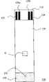
图1绘示本发明实施例的检测试片100,而图2则绘示检测试片100的结构分解图,并以虚线绘示出各元组件的对应关系。本发明的检测试片100包含绝缘基板110、导电层120、绝缘垫高层130、及上盖150。导电层120包含电极组122以及辨识单元127,其中辨识单元127包含构成元件组128及连结元件组129。在此实施例中,构成元件组128包含5个构成元件128a、128b、128c、128d、及128e,而连结元件组129包含二个连结元件129a及129b。连结元件129a与各构成元件的的一端连接,而连结元件129b则与各构成元件的另一端连接,如图2所示。在此实施例中,电极组122包含相互绝缘的工作电极123及参考电极124。FIG. 1 shows a
本发明并不限定辨识单元127中所含构成元件的数量、形状,且辨识单元127可设置于绝缘基板110的任一表面,并不局限与电极组122在同一表面。一般来说,构成元件组128包含至少一个部分或完全贯穿绝缘基板110的孔洞(如图2中的元件H)于其中构成元件上,使得该构成元件与连结元件组129之间形成开路结构。在本实施例中孔洞H完全贯穿绝缘基板110,其由绝缘基板110上的贯穿孔h1、导电层120中的贯穿孔h2、及绝缘垫高层130上的贯穿孔h3所构成。通过控制孔洞的数量及位置,可改变辨识单元127的电性特征(如二个连结元件129a及129b之间的阻抗值),并可据此而辨别检测试片100。The present invention does not limit the number and shape of the constituent elements contained in the
绝缘基板110具有电绝缘性,其材料可包含但不限于:聚氯乙烯(PVC)、玻璃纤维(FR-4)、聚酯(polyester)、电木板(bakelite)、聚对苯二甲酸二乙酯(PET)、聚碳酸酯(PC)、聚丙烯(PP)、聚乙烯(PE)、聚苯乙烯(PS)、或陶瓷等。The insulating
导电层120的材料可为任何导电物质,例如碳胶、金银胶、铜胶、碳银混合胶、或其类似物及组合等。在实施例中,导电层120是由导电银胶层以及置于导电银胶层之上的导电碳粉层所组成,一般而言,导电碳粉层的阻抗远大于导电银胶层或其他金属胶层。辨识单元127可通过导电银胶层与导电碳粉层做搭配,以计算各个构成元件所组成的阻抗值,作为检测试片的排列设计。各构成元件可分别具有不同的长度或宽度以形成具有不同阻值的电阻,且各构成元件与两连结元件之间可选择性地形成通路结构或通过孔洞而形成开路结构。一般来说,当N个构成元件各自具有不同的阻抗值并搭配不同的孔洞数量及位置,可组合出2N种阻抗值。当检测试片100置入量测装置时,量测装置可根据两连结元件之间的阻抗值而辨别检测试片100,亦可进而采行相对应校正参数或模式进行量测。需注意本发明的构成元件128不限于电阻。The material of the
本发明并不限制工作电极123、参考电极124、及辨识单元127的安排方式,亦不限制电极的数量,可根据实际应用所需而增加其他电极。一般来说,只要各电极及辨识单元之间彼此绝缘即已足够。The present invention does not limit the arrangement of the working
绝缘垫高层130置于导电层120之上,且绝缘垫高层130包含开口132a,以暴露导电层120的一部分。一般而言,开口132a只要能够暴露出部分的工作电极123及部分的参考电极124即已足够,本发明并不限制开口132a的形状。此外,绝缘垫高层130的设计亦暴露出导电层120的另一部分,以使导电层120可与量测装置(如图6的630)电性相接。绝缘垫高层130的材料可包含但不限于PVC绝缘胶带、PET绝缘胶带、热干燥型绝缘漆或紫外光固化型绝缘漆。The insulating
上盖150置于绝缘垫高层130之上,且覆盖开口132a。介于绝缘基板110与上盖150之间的部分形成具毛细吸引力的取样空间(即反应区132)。当取样空间的面积固定时,其体积可取决于绝缘垫高层130的厚度。一般而言,绝缘垫高层130的厚度介于约0.005毫米至约0.3毫米,然不在此限。此外,在制造过程中,可将已裁切出开口132a的绝缘垫高层130放置于绝缘基板110与导电层120上,亦可以印刷的方式避开开口132a及用以与量测装置电性相接的区域,而直接形成绝缘垫高层130于部分的绝缘基板110与导电层120之上。The
本发明的检测试片100还包含置于开口132a中的反应层140,其具有专一性辨识生物材料或信号的能力,其中反应层140的材料随样品不同而有所不同,例如可为氧化还原酶或电子媒介物(如亚铁类材料),用以与样品产生化学反应。一般而言,反应层140至少覆盖部分的参考电极124及工作电极123。The
本发明的上盖150可为透明或半透明材料,以方便观察反应区132是否已填入样品,避免样品未填入前即进行检测,而导致错误的结果。上盖150的接近反应区132的下表面可涂布亲水材料,以加强反应区132内部壁面的毛细作用,用以更迅速有效地将样品导入反应区132中。上盖150还包含相应于开口132a末端的通气孔153,用以排出反应区132内的气体以加强毛细作用,一般而言,通气孔153靠近开口132a末端。本发明并不限制通气孔153的形状,举例来说,通气孔153可为圆形、椭圆形、长方形、菱形等。The
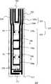
图3、图4、图5A及图5B为根据本发明不同实施例所绘示的检测试片300、400、500a、及500b,须注意到为方便说明并未绘示绝缘垫高层及上盖。参考图3,检测试片300包含绝缘基板310、以及相互绝缘的工作电极323、参考电极324、感测电极325、二个侦测单元326及辨识单元327,其中辨识单元327包含构成元件组328及连结元件组329。在此实施例中,构成元件组328包含五个构成元件328a、328b、328c、328d、及328e,而连结元件组329包含连结元件329a及329b,其中各个构成元件的二端分别与连结元件329a及329b连接,形成并联。检测试片300亦包含了两个孔洞P1及P2于构成元件328a及328d上,使得构成元件328a、328d分别与连结元件组329之间形成开路结构。当检测试片300与量测装置(如图6所绘示的量测装置630)电性连接时,构成元件328b、328c、及328e可分别形成三个电性回路,而构成元件328a、328d则分别为断路,因此量测装置将透过连结元件组329量测到由构成元件328b、328c、及328e所形成的回路的总电性特征(如总等效阻抗值),并由此辨识检测试片300。Fig. 3, Fig. 4, Fig. 5A and Fig. 5B are the
在图3所示的实施例中,感测电极325为ㄇ字型电极,其与工作电极323及参考电极324电性绝缘。感测电极325设置于工作电极323及参考电极324之间,用以感测检测试片300与量测装置(如图6所绘示的量测装置630)间的电性连接。一般来说,感测电极325透过回路产生电信号,而达到指定开机的功效。举例来说,当检测试片300置入量测装置后,感测电极325可与量测装置间形成回路,而启动量测装置。In the embodiment shown in FIG. 3 , the
侦测单元326的主要功能在于确认样品是否已适当地覆盖反应区332。一般来说,侦测单元326是对应反应区332的底部而设置,使得当液态样品注入反应区332时,将依序接触到参考电极324、工作电极323、及侦测单元326。一旦样品到达反应区底部的二个侦测单元326,此样品可做为这二个侦测单元326间的电性连接,而使其之间的阻抗值变小。侦测单元326可通过与基板上的其他电极或电性结构耦合,而达到在小面积的基板上实现多项检测功能的目的。在此实施例中,二个侦测单元326的一端分别与参考电极324及连结元件329a连接。如此,量测装置可提供电压于参考电极324及连结元件329a之间,一旦样品到达反应区332底部的侦测单元326,便可使参考电极324及连结元件329a间有足够的电流流通,而确认样品已适当地覆盖反应区332。在其他实施例中,二个侦测单元326的一端可分别连接至其他电极,例如分别连接至工作电极323及连结元件329b。The main function of the
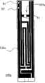
参考图4,检测试片400包含绝缘基板410、以及相互绝缘的工作电极423、参考电极424、二个侦测单元426及辨识单元427,其中辨识单元427包含构成元件428a、428b、428c及连结元件429a、429b,且各个构成元件的二端分别与连结元件429a及429b连接。二个侦测单元426的一端分别与参考电极424及连结元件429a连接,用以确认样品是否已适当地覆盖反应区432。在其他实施例中,侦测单元426中的一个或二个可为独立电极,并与其他电极相互绝缘。检测试片400亦包含了两个孔洞P1及P2于构成元件428a及428c上,使构成元件428a及428c与连结元件429间形成开路结构。孔洞P1及P2可为贯穿绝缘基板410的贯穿孔亦可为未贯穿绝缘基板410的凹槽。在此实施例中,以不同长度及形状的导电碳粉形成各构成元件,以产生具有不同阻抗值的构成元件。一般来说,构成元件的阻抗值可利用导电碳粉的长度或宽度而调整,更进一步地,可搭配其他金属胶层(如银胶层)来调整。With reference to Fig. 4,
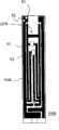
在图5A中,检测试片500a具有孔洞P1于构成元件上,用以破坏该构成元件与连接元件间的电性回路,其破坏方式可采部分或完成贯穿绝缘基板而达成。在图5B中,检测试片500b具有二个孔洞P1及P2于二个不同的构成元件上。因此,检测试片500a的辨识单元527a及检测试片500b的辨识单元527b将具有不同的电性特征,由此可辨别检测试片500a及500b。举例来说,当检测试片500a或500b置入量测装置时,量测装置可透过接收对应辨识单元527a或527b的电性特征的信号,而得以辨别检测试片500a及500b,进而采行相对应校正参数或模式进行量测。In FIG. 5A , the
在本发明其他实施例中,可指定工作电极或量测电极的不同位置而达到启动量测装置或其他的感测功能。举例而言,参考图5A及5B,在参考电极524a或524b的检测端(将连接至量测装置的端点)设置2个检测点S1、S2,其中检测点S2可用以接地,当二个检测点S1、S2与量测装置连接成电性回路,则指定启动量测装置。In other embodiments of the present invention, different positions of the working electrode or the measuring electrode can be designated to activate the measuring device or other sensing functions. For example, with reference to Figures 5A and 5B, two detection points S1 and S2 are set at the detection end of the
本发明并不限制构成元件的数量,亦应了解到,构成元件的数量、形状、及电性可由设计者根据实际应用自行设定,其中每一构成元件可选择性地以孔洞破坏其与连结元件组之间的电性连接,由此可形成多个不同的等效阻抗值。换言之,当具有N个构成元件时,最多将可组合出2N个识别码。亦即,通过选择性的破坏每一构成元件,并配合每个构成元件的阻抗大小,即可组合成多个独特的识别码。辨识单元将可由此用以表示不同功能的检测试片,或不同批次的检测试片。破坏构成元件回路的方式可为贯穿绝缘基板的贯穿孔或未贯穿绝缘基板的凹槽。本发明亦不限制凹槽或贯穿孔的形状与大小。需注意的是,本发明的N个构成元件可为各种无源元件,如电阻、电感、或电容等。The present invention does not limit the number of constituent elements, and it should also be understood that the number, shape, and electrical properties of the constituent elements can be set by the designer according to the actual application, wherein each constituent element can selectively destroy its connection with a hole The electrical connection between component groups can form multiple different equivalent impedance values. In other words, when there are N constituent elements, at most 2N identification codes can be combined. That is, by selectively destroying each constituent element and matching the impedance of each constituent element, multiple unique identification codes can be combined. The identification unit can thus be used to represent test strips with different functions, or test strips of different batches. The way of destroying the circuits of the components can be through holes penetrating through the insulating substrate or grooves not penetrating the insulating substrate. The present invention does not limit the shape and size of the groove or the through hole. It should be noted that the N constituent elements of the present invention can be various passive elements, such as resistors, inductors, or capacitors.
图6为根据本发明实施例所绘示的生化感测系统600的方块示意图,其包含检测试片300及量测装置630。检测试片300包含工作电极323、参考电极324、感测电极325、二个侦测单元326、辨识单元327、及两个孔洞P1、P2,其中辨识单元327包含构成元件328a、328b、328c、328d、328e及连结元件329a、329b,且孔洞P1及P2分别位于构成元件328a及328d上,如图3所述。本发明的连结元件329a、329b在于提供各构成元件328a、328b、328c、328d、328e与量测装置630电连接的途径。FIG. 6 is a schematic block diagram of a
量测装置630包含连接器640及耦合至连接器640的微处理单元650,其中微处理单元650内建数字数据655,其可例如为校正参数、检测模式、或其他资讯等。连接器640具有对应各电极及辨识单元327的连接端子,其中工作电极323、参考电极324、感测电极325、侦测单元326、及辨识单元327透过与连接器640的连接端子之间的相接而与量测装置630电性相连。The
当检测试片300与连接器640连接,感测电极325与连接器640之间将形成回路,而使微处理单元650启动量测装置630。此外,由于辨识单元327的多个构成元件分别有不同状态,因此与连接器640间的连接将有不同的形式,由此而产生对应辨识单元327所表示的识别码的信号至微处理单元650。举例来说,当检测试片300与量测装置630电性连接时,构成元件328a及328d无法与连接器640形成电性连接,仅构成元件328b、328c、及328e可形成电性回路。连接器640可透过连结元件329a及329b接收对应此电性特征的信号,并将此信号传送至微处理器650。微处理单元650则可将根据此信号进行辨识,并自数据655中选择相应此信号的参数或模式以执行。量测装置630还包含用以显示各种量测结果的显示器660,以及用以提供所需电源的电源670。在另一实施例中,显示器660及电源670可为外接装置,而不包含于量测装置630中。When the
简言之,本发明的辨识单元是供辨识与指定在量测装置中所内建的数据,其中量测装置内建有复阵列相应于试片上辨识单元所表示的识别码的校正参数、检测模式、或其他资讯。本发明所揭示的生化感测系统不但达到无须密码卡的目的并减少密码卡制造成本、提高了检测方便性、且可避免人为操作的疏失。In short, the identification unit of the present invention is used to identify and specify the data built in the measuring device, wherein the measuring device is built with a complex array of calibration parameters corresponding to the identification code represented by the identification unit on the test piece, detection mode, or other information. The biochemical sensing system disclosed by the present invention not only achieves the purpose of eliminating the need for a code card, reduces the manufacturing cost of the code card, improves the convenience of detection, but also avoids the negligence of human operation.
以上所述仅为本发明的优选实施例而已,并非用以限定本发明的权利要求;凡其它未脱离本发明所揭示的精神下所完成的等同改变或修饰,均应包含在权利要求内。The above descriptions are only preferred embodiments of the present invention, and are not intended to limit the claims of the present invention; all other equivalent changes or modifications that do not deviate from the spirit disclosed in the present invention shall be included in the claims.
Claims (27)
Priority Applications (1)
| Application Number | Priority Date | Filing Date | Title |
|---|---|---|---|
| CN200810214831.3ACN101661033B (en) | 2008-08-29 | 2008-08-29 | Test strips, biochemical sensing systems, and measuring devices |
Applications Claiming Priority (1)
| Application Number | Priority Date | Filing Date | Title |
|---|---|---|---|
| CN200810214831.3ACN101661033B (en) | 2008-08-29 | 2008-08-29 | Test strips, biochemical sensing systems, and measuring devices |
Publications (2)
| Publication Number | Publication Date |
|---|---|
| CN101661033Atrue CN101661033A (en) | 2010-03-03 |
| CN101661033B CN101661033B (en) | 2014-04-23 |
Family
ID=41789174
Family Applications (1)
| Application Number | Title | Priority Date | Filing Date |
|---|---|---|---|
| CN200810214831.3AActiveCN101661033B (en) | 2008-08-29 | 2008-08-29 | Test strips, biochemical sensing systems, and measuring devices |
Country Status (1)
| Country | Link |
|---|---|
| CN (1) | CN101661033B (en) |
Cited By (8)
| Publication number | Priority date | Publication date | Assignee | Title |
|---|---|---|---|---|
| CN103076441A (en)* | 2011-10-25 | 2013-05-01 | 华广生技股份有限公司 | Biological sensing measuring system with test piece information capable of being checked bidirectionally and detection test piece structure |
| CN103105413A (en)* | 2011-11-15 | 2013-05-15 | 达尔生技股份有限公司 | Biosensor and biometric system |
| WO2013102448A1 (en)* | 2012-01-06 | 2013-07-11 | 达尔生技股份有限公司 | Biosensor and biomeasurement system |
| WO2014063419A1 (en)* | 2012-10-25 | 2014-05-01 | 广州万孚生物技术股份有限公司 | Analysis and detection apparatus with humidity sensing function, and analysis and detection method |
| CN103797364A (en)* | 2011-05-25 | 2014-05-14 | 曼多公司 | A cartridge for test strips and a method for including a calibration code onto the cartridge and for reading the code |
| CN105424916A (en)* | 2015-12-09 | 2016-03-23 | 桂林优利特医疗电子有限公司 | Electrode codes of biosensor test paper, recognition device and recognition method |
| CN108414594A (en)* | 2017-02-10 | 2018-08-17 | 琦芯科技股份有限公司 | Biological sensing test piece made of non-etching solvent and its making method |
| CN114544733A (en)* | 2020-11-25 | 2022-05-27 | 五鼎生物技术股份有限公司 | Biochemical test piece |
Citations (3)
| Publication number | Priority date | Publication date | Assignee | Title |
|---|---|---|---|---|
| US20050279647A1 (en)* | 2004-06-18 | 2005-12-22 | Terry Beaty | System and method for coding information on a biosensor test strip |
| TW200724907A (en)* | 2005-12-23 | 2007-07-01 | Apex Biotechnology Corp | Electrochemical test strip |
| TWM334325U (en)* | 2007-09-05 | 2008-06-11 | Apex Biotechnology Corp | Biochemical test strip |
- 2008
- 2008-08-29CNCN200810214831.3Apatent/CN101661033B/enactiveActive
Patent Citations (3)
| Publication number | Priority date | Publication date | Assignee | Title |
|---|---|---|---|---|
| US20050279647A1 (en)* | 2004-06-18 | 2005-12-22 | Terry Beaty | System and method for coding information on a biosensor test strip |
| TW200724907A (en)* | 2005-12-23 | 2007-07-01 | Apex Biotechnology Corp | Electrochemical test strip |
| TWM334325U (en)* | 2007-09-05 | 2008-06-11 | Apex Biotechnology Corp | Biochemical test strip |
Cited By (14)
| Publication number | Priority date | Publication date | Assignee | Title |
|---|---|---|---|---|
| CN103797364B (en)* | 2011-05-25 | 2016-05-25 | 曼多公司 | Body fluid measures examination barrel, for comprising the method for calibration code and identify the method for this yard on this box |
| CN103797364A (en)* | 2011-05-25 | 2014-05-14 | 曼多公司 | A cartridge for test strips and a method for including a calibration code onto the cartridge and for reading the code |
| CN103076441A (en)* | 2011-10-25 | 2013-05-01 | 华广生技股份有限公司 | Biological sensing measuring system with test piece information capable of being checked bidirectionally and detection test piece structure |
| CN103076441B (en)* | 2011-10-25 | 2015-08-19 | 华广生技股份有限公司 | Biosensing measurement system with two-way verification of test piece information |
| CN103105413A (en)* | 2011-11-15 | 2013-05-15 | 达尔生技股份有限公司 | Biosensor and biometric system |
| CN103105413B (en)* | 2011-11-15 | 2015-10-21 | 达尔生技股份有限公司 | Biosensor and biometric system |
| WO2013102448A1 (en)* | 2012-01-06 | 2013-07-11 | 达尔生技股份有限公司 | Biosensor and biomeasurement system |
| CN104040348A (en)* | 2012-01-06 | 2014-09-10 | 达尔生技股份有限公司 | Biosensors and biometric systems |
| CN104040348B (en)* | 2012-01-06 | 2016-02-10 | 达尔生技股份有限公司 | Biosensors and biometric systems |
| WO2014063419A1 (en)* | 2012-10-25 | 2014-05-01 | 广州万孚生物技术股份有限公司 | Analysis and detection apparatus with humidity sensing function, and analysis and detection method |
| CN105424916A (en)* | 2015-12-09 | 2016-03-23 | 桂林优利特医疗电子有限公司 | Electrode codes of biosensor test paper, recognition device and recognition method |
| CN108414594A (en)* | 2017-02-10 | 2018-08-17 | 琦芯科技股份有限公司 | Biological sensing test piece made of non-etching solvent and its making method |
| CN114544733A (en)* | 2020-11-25 | 2022-05-27 | 五鼎生物技术股份有限公司 | Biochemical test piece |
| CN114544733B (en)* | 2020-11-25 | 2024-06-11 | 五鼎生物技术股份有限公司 | Biochemical test piece |
Also Published As
| Publication number | Publication date |
|---|---|
| CN101661033B (en) | 2014-04-23 |
Similar Documents
| Publication | Publication Date | Title |
|---|---|---|
| CN101661033A (en) | Test strip, biochemical sensing system and measuring device | |
| TWI412740B (en) | Test strip, biochemical test system, and measurement device | |
| JP5091239B2 (en) | Calibration data transfer system and method | |
| US7625473B2 (en) | Test strip with identification function and test instrument using the same | |
| US7316929B2 (en) | Auto-calibration label and apparatus comprising same | |
| EP2171439B1 (en) | Biosensor calibration system | |
| JP5091238B2 (en) | Measurement system for individualized inspection sensors | |
| CN101430327B (en) | Detection test piece with identification function and detection device thereof | |
| EP2067865A1 (en) | Biochemical test system, measurement device, and biochemical test strip | |
| EP1729128B1 (en) | A coding module, a bio sensing meter and a method for operating a bio sensing meter | |
| US20110042211A1 (en) | Biochemical test strip, measurement device, and biochemical test system | |
| EP3163300B1 (en) | Resistance structure | |
| US20060271307A1 (en) | Coding module, a bio sensing meter and a system for operating a bio sensing meter | |
| CN102023180B (en) | Biochemical sensing system, measuring device, biochemical sensing test piece and manufacturing method thereof | |
| US20100206728A1 (en) | Biochemical test system, measurement device, and biochemical test strip | |
| US20090041625A1 (en) | Auto-calibration label and method of forming the same | |
| TWM343160U (en) | Biochemical test system, measurement device, and biochemical test strip | |
| CN201203615Y (en) | Biochemical sensing system, measuring device and biochemical sensing test piece | |
| CN101451992A (en) | Biochemical sensing system, measuring device, biochemical sensing test piece and manufacturing method thereof | |
| CN201355357Y (en) | Biochemical sensing test strip, biochemical sensing system and measuring device | |
| CN201707331U (en) | Biochemical sensing test strip, measuring device, and biochemical sensing system | |
| KR20120005733A (en) | Bio Sensing Device | |
| US20150083589A1 (en) | Bio sensing device | |
| CN201207049Y (en) | Biochemical sensing system, measuring device and biochemical sensing test piece | |
| CN104034767B (en) | Identification information unit, identification massaging device and biosensor |
Legal Events
| Date | Code | Title | Description |
|---|---|---|---|
| C06 | Publication | ||
| PB01 | Publication | ||
| C10 | Entry into substantive examination | ||
| SE01 | Entry into force of request for substantive examination | ||
| C14 | Grant of patent or utility model | ||
| GR01 | Patent grant |