CN101651034B - Non-contact connector - Google Patents
Non-contact connectorDownload PDFInfo
- Publication number
- CN101651034B CN101651034BCN2009101299522ACN200910129952ACN101651034BCN 101651034 BCN101651034 BCN 101651034BCN 2009101299522 ACN2009101299522 ACN 2009101299522ACN 200910129952 ACN200910129952 ACN 200910129952ACN 101651034 BCN101651034 BCN 101651034B
- Authority
- CN
- China
- Prior art keywords
- light
- fixed
- elliptical
- rotating
- reflector
- Prior art date
- Legal status (The legal status is an assumption and is not a legal conclusion. Google has not performed a legal analysis and makes no representation as to the accuracy of the status listed.)
- Expired - Fee Related
Links
- 230000003287optical effectEffects0.000claimsabstractdescription113
- 230000006854communicationEffects0.000claimsdescription76
- 238000004891communicationMethods0.000claimsdescription76
- 238000010276constructionMethods0.000claimsdescription27
- 238000004804windingMethods0.000claimsdescription19
- 230000002457bidirectional effectEffects0.000claimsdescription12
- 239000013307optical fiberSubstances0.000claimsdescription10
- 230000000694effectsEffects0.000claimsdescription3
- 238000004020luminiscence typeMethods0.000claims1
- 230000009471actionEffects0.000abstractdescription3
- 238000000034methodMethods0.000description24
- 238000013461designMethods0.000description17
- 239000000470constituentSubstances0.000description14
- 238000010586diagramMethods0.000description10
- 238000009434installationMethods0.000description6
- 230000033001locomotionEffects0.000description6
- 238000012545processingMethods0.000description6
- 230000005540biological transmissionEffects0.000description4
- 230000000903blocking effectEffects0.000description4
- 235000012489doughnutsNutrition0.000description4
- 238000007792additionMethods0.000description3
- 239000012634fragmentSubstances0.000description3
- 230000007175bidirectional communicationEffects0.000description2
- 230000005674electromagnetic inductionEffects0.000description2
- 238000010030laminatingMethods0.000description2
- 238000004519manufacturing processMethods0.000description2
- 230000007246mechanismEffects0.000description2
- 230000002040relaxant effectEffects0.000description2
- 238000013459approachMethods0.000description1
- 238000011161developmentMethods0.000description1
- 230000018109developmental processEffects0.000description1
- 238000005516engineering processMethods0.000description1
- 230000014509gene expressionEffects0.000description1
- 238000002955isolationMethods0.000description1
- 230000000149penetrating effectEffects0.000description1
- 230000002093peripheral effectEffects0.000description1
- 230000008569processEffects0.000description1
- 230000000644propagated effectEffects0.000description1
- 230000004044responseEffects0.000description1
Images


Classifications
- H—ELECTRICITY
- H10—SEMICONDUCTOR DEVICES; ELECTRIC SOLID-STATE DEVICES NOT OTHERWISE PROVIDED FOR
- H10F—INORGANIC SEMICONDUCTOR DEVICES SENSITIVE TO INFRARED RADIATION, LIGHT, ELECTROMAGNETIC RADIATION OF SHORTER WAVELENGTH OR CORPUSCULAR RADIATION
- H10F55/00—Radiation-sensitive semiconductor devices covered by groups H10F10/00, H10F19/00 or H10F30/00 being structurally associated with electric light sources and electrically or optically coupled thereto
- G—PHYSICS
- G02—OPTICS
- G02B—OPTICAL ELEMENTS, SYSTEMS OR APPARATUS
- G02B6/00—Light guides; Structural details of arrangements comprising light guides and other optical elements, e.g. couplings
- G02B6/24—Coupling light guides
- G02B6/36—Mechanical coupling means
- G02B6/3604—Rotary joints allowing relative rotational movement between opposing fibre or fibre bundle ends
- G—PHYSICS
- G02—OPTICS
- G02B—OPTICAL ELEMENTS, SYSTEMS OR APPARATUS
- G02B6/00—Light guides; Structural details of arrangements comprising light guides and other optical elements, e.g. couplings
- G02B6/24—Coupling light guides
- G02B6/36—Mechanical coupling means
- H—ELECTRICITY
- H04—ELECTRIC COMMUNICATION TECHNIQUE
- H04B—TRANSMISSION
- H04B10/00—Transmission systems employing electromagnetic waves other than radio-waves, e.g. infrared, visible or ultraviolet light, or employing corpuscular radiation, e.g. quantum communication
- H04B10/80—Optical aspects relating to the use of optical transmission for specific applications, not provided for in groups H04B10/03 - H04B10/70, e.g. optical power feeding or optical transmission through water
Landscapes
- Physics & Mathematics (AREA)
- General Physics & Mathematics (AREA)
- Optics & Photonics (AREA)
- Electromagnetism (AREA)
- Engineering & Computer Science (AREA)
- Computer Networks & Wireless Communication (AREA)
- Signal Processing (AREA)
- Optical Couplings Of Light Guides (AREA)
- Optical Communication System (AREA)
- Photo Coupler, Interrupter, Optical-To-Optical Conversion Devices (AREA)
- Mechanical Coupling Of Light Guides (AREA)
Abstract
Translated fromChinese
Description
Translated fromChinese技术领域technical field
本发明涉及一种非接触式连接器(10)。The invention relates to a contactless connector (10).
背景技术Background technique
在现有技术中,已经执行了旋转侧与固定侧之间的数据发送和接收。例如,相机设置在可旋转底座上,并且来自相机的图像信号等发送到固定侧信号处理部分等等。在这种情况下,通过相机与信号处理部分之间的导线的直接连接,来自相机的图像信号发送到固定侧信号处理部分。然而,由于无线技术的最新发展,即使在没有导线直接连接时,已经可以在旋转侧与固定侧之间发送和接收信号(数据)。In the prior art, data transmission and reception between the rotating side and the fixed side have been performed. For example, a camera is set on a rotatable base, and image signals and the like from the camera are sent to a fixed-side signal processing section and the like. In this case, the image signal from the camera is sent to the fixed-side signal processing section through direct connection of wires between the camera and the signal processing section. However, thanks to recent developments in wireless technology, it has become possible to send and receive signals (data) between the rotating side and the fixed side even when there is no direct connection with wires.
然而,为了在旋转侧上进行图像拍摄或其它操作,必需向旋转侧供电;但是存在如下问题:在没有接触的情况下,很难从固定侧向旋转侧供电。However, in order to perform image capture or other operations on the rotating side, it is necessary to supply power to the rotating side; but there is a problem that it is difficult to supply power to the rotating side from the fixed side without contact.
在过去,在解决这些问题时,为了传输信号,在盘状旋转体的上部上设置有多个光发射元件并且在与光发射元件相对的位置上设置有固定体的多个光接收元件,同时以非接触方式发送和接收数据;或者为了传送电力,在旋转侧与固定侧之间配置旋转变压器,从而实现从固定侧到旋转侧的非接触式供电的方法(例如,参见日本专利申请特开No.2002-75760和日本专利申请特开No.2006-197553)。In the past, when solving these problems, in order to transmit signals, a plurality of light-emitting elements were provided on the upper portion of the disk-shaped rotating body and a plurality of light-receiving elements of a fixed body were arranged at positions opposite to the light-emitting elements, while Send and receive data in a non-contact manner; or in order to transmit power, a resolver is arranged between the rotating side and the fixed side, thereby realizing a method of non-contact power supply from the fixed side to the rotating side (see, for example, Japanese Patent Application Laid-Open No. 2002-75760 and Japanese Patent Application Laid-Open No. 2006-197553).
然而,在日本专利申请特开No.2002-75760中,当数据通信的速度增大时,不总是能够将所有数据从旋转体的光发射元件发送到固定体的光接收元件。也就是说,在日本专利申请特开No.2002-75760中,来自该光发射元件的光路被切换到另一个光发射元件,使得随着旋转体的旋转光学部件之间的非接触式光连接没有中断。当利用这个切换方法时,随着数据通信速度的增大,会出现如下情况:数据发送比切换光路的处理时间更快,由此出现如下问题:不能够保证高速通信的连续性。However, in Japanese Patent Application Laid-Open No. 2002-75760, when the speed of data communication increases, it is not always possible to transmit all data from the light-emitting element of the rotating body to the light-receiving element of the fixed body. That is, in Japanese Patent Application Laid-Open No. 2002-75760, the optical path from one light-emitting element is switched to another light-emitting element so that the non-contact optical connection between optical parts follows the rotation of the rotating body There is no interruption. When this switching method is used, as the data communication speed increases, there are cases where data transmission is faster than the processing time for switching optical paths, whereby a problem arises that the continuity of high-speed communication cannot be guaranteed.
另外,在日本专利申请特开No.2006-197553中,由于光接收元件切换不再是必需的,所以能够提供高速通信;但是需要控制旋转速度的机构(齿轮等),并且必须考虑多个机构部件的间隙。此外,来自光发射元件的光在被接收之前被分散,从而发出的光仅仅一部分到达光接收元件,并且由此引起无法应用于模拟信号通信的问题。Also, in Japanese Patent Application Laid-Open No. 2006-197553, high-speed communication can be provided because light-receiving element switching is no longer necessary; but a mechanism (gear, etc.) for controlling the rotation speed is required, and multiple mechanisms must be considered Part clearance. Furthermore, the light from the light-emitting element is dispersed before being received, so that only a part of the emitted light reaches the light-receiving element, and thus causes a problem that it cannot be applied to analog signal communication.
根据以上问题提出了本发明,并且本发明的目的在于提供一种非接触式连接器,其中,该非接触式连接器使得不需要考虑间隙等就可以在确保高速通信连续性的同时进行多通道模拟通信。The present invention has been made in view of the above problems, and an object of the present invention is to provide a non-contact connector that enables multi-channel communication while ensuring continuity of high-speed communication without taking into account gaps and the like. Analog communication.
发明内容Contents of the invention
鉴于上述内容,本发明的目的在于提供一种非接触式连接器10,包括:旋转体1;固定体2;分别安装在该旋转体上的旋转侧光发射元件A13和旋转侧光接收元件A 14;以及分别安装在该固定体上的固定侧光发射元件A 23和固定侧光接收元件A(24),其中,通过三维椭圆状反射体A 500的发光侧焦点F1 3位于该旋转体1一侧上并且光接收侧焦点F25位于固定体2一侧上,利用从发光侧焦点F1 3到光接收侧焦点F2 5的会聚作用构造下述光路:从设置在发光侧焦点F1 3的旋转侧光发射元件A 13经由在其中三维椭圆状反射体的一部分用作反射镜表面的固定侧椭圆部分反射镜8到设置在光接收侧焦点F2 5的固定侧光接收元件A 24的光路并且利用从发光侧焦点F1 3到光接收侧焦点F2 5的会聚作用构造下述并发双向单通道光路:从设置在三维椭圆状反射体B 501的发光侧焦点F1 3的固定侧光发射元件A 23经由旋转侧椭圆部分反射镜6到达设置在光接收侧焦点F2 5的旋转侧光接收元件A 14,在该旋转侧椭圆部分反射镜6中该三维椭圆状反射体B 501的一部分用作反射镜面;以及通过同时且双向地在该旋转体1与固定体2之间构造多个单通道光路并发且双向地执行非接触多通道光通信。In view of the above, the object of the present invention is to provide a
通过这种手段,例如,不管随着旋转体1的旋转该旋转侧发光部分13的位置如何,由于椭圆反射镜(固定侧椭圆部分反射镜8)的几何形状的会聚效应,从旋转侧光发射元件13发出的光总是被导向特定的固定侧光接收元件24,从而能够实现未中断的单光路,并且能够确保连续通信。接下来,当构造多个这种光路并且该多个这种光路被做成双向时,能够确保多通道和双向通信。By this means, for example, regardless of the position of the rotating side light-emitting
该非接触式连接器10,其中,通过下述构造双通道通信系统:第一通道的光路,在该第一通道的光路中,固定侧椭圆片段形状反射镜A 81的发光侧焦点F1 3位于旋转轴4上,并且从使光会聚在发光侧焦点F1 3的方式安装的该旋转侧光发射元件A 13发出的光被该固定侧椭圆片段形状反射镜A 81反射以到达安装在该固定侧椭圆片段形状反射镜A 81的另一个焦点F2 5的固定侧光接收元件A 24,其中固定侧椭圆片段形状反射镜A 81为片段形状的该固定侧椭圆部分反射镜8;以及第二通道的光路,在该第二通道的光路中,从使光会聚在旋转侧椭圆片段形状反射镜B 62的发光侧焦点上的方式安装的旋转侧光发射元件B 131发出的光被以使得另一个光接收侧焦点位于旋转轴4上的方式安装的旋转侧椭圆片段形状反射镜B 62反射以到达在该光接收侧焦点的固定侧光接收元件B 241,该旋转侧椭圆片段形状反射镜B 62为片段形状的该旋转侧椭圆部分反射镜6;同时该光路被构造为使得:通过使该固定侧椭圆片段形状反射镜A81和该旋转侧椭圆片段形状反射镜B 62是相同椭圆体的部分反射镜,光发射元件的基本100%的发光量分别被该固定侧光接收元件A 24和该固定侧光接收元件B 241接收,从而在该固定侧光接收元件A 24和该固定侧光接收元件B 241之间的光接收特征的差别是可忽略的,并且由此实现模拟信号通信。The
该非接触式连接器10,其中,对于1通道光路构造,在该1通道光路构造中,固定侧椭圆环形反射镜A 91的发光侧焦点F1 3位于该旋转轴4上,从以使光会聚在发光侧焦点F1 3上的方式安装的旋转侧光发射元件A 13发出的光被该固定侧椭圆环形反射镜A 91反射以到达安装在该固定侧椭圆环形反射镜A 91的光接收侧焦点F2 5的固定侧光接收元件A24,其中该固定侧椭圆环形反射镜A 91为环形的该固定侧椭圆部分反射镜8;通过沿着该旋转轴4的平行移动且层叠该1通道光路构造而形成的三个或更多通道的通信系统将多个光路构造为使得:光发射元件的基本100%的发光量被接收,并且用于三个或更多通道的多个固定侧椭圆部分反射镜8是相同椭圆体的部分反射镜,由此使得在多个光接收元件之间的光接收特征的差别是可忽略的,并且由此实现模拟信号通信。The
该非接触式连接器10,其中通过下面的方式将构造并发双向单通道通信系统的构造方法应用到对于多个光路的构造,从而构造并发双向多通道通信系统:利用关于旋转轴4上的指定点的面对称,将从该旋转侧光发射元件A 13经由该固定侧椭圆部分反射镜8到达该固定侧光接收元件A 24的光路构造为从该固定侧光发射元件A 23经由该旋转侧椭圆部分反射镜6至该旋转侧光接收元件A 14的光路。The
利用关于垂直于旋转轴4并且穿过旋转轴4上的任意点的面的面对称地构造多个“以这种方式构造了从旋转侧到固定侧的光路”的结构,并且多通道双向模拟通信系统被实现为从固定侧到旋转侧的光路。A plurality of structures "constructing the optical path from the rotating side to the fixed side in this way" are constructed symmetrically with respect to a plane perpendicular to the rotating
该非接触式连接器10,其中,当构造所述双通道通信系统时,对于该固定侧椭圆部分反射镜8和该旋转侧椭圆部分反射镜6,该固定侧椭圆片段形状反射镜A 81和该旋转侧椭圆片段形状反射镜B 62的形状没有被形成为相同椭圆体的部分片段形状反射镜。当构造三个或更多通道的通信系统时,多个固定侧椭圆部分反射镜8没有被形成为相同椭圆体的部分反射镜。通过所述固定侧椭圆环形反射镜A 91、形成了该固定侧椭圆部分反射镜8的该固定侧椭圆片段形状反射镜A 81和该固定侧椭圆片段形状反射镜B 82;与形成了该旋转侧椭圆部分反射镜6的该旋转侧椭圆片段形状反射镜A 61和该旋转侧椭圆片段形状反射镜B 62以及该旋转侧椭圆环形反射镜A 71的任意组合构造多通道通信系统。The
通过这个手段,利用椭圆片段形状反射镜能够构造多达两个通道,利用椭圆环形反射镜能够构造三个或更多通道,通过放松通道之间的一致性能够构造多通道系统,并且通过椭圆片段形状反射镜和椭圆环形反射镜的任意组合能够构造多通道系统。By this means, up to two channels can be constructed using elliptical segment shape mirrors, three or more channels can be constructed using elliptical ring mirrors, multi-channel systems can be constructed by relaxing the coherence between channels, and by elliptical segment Any combination of shape mirrors and elliptical ring mirrors enables the construction of multi-channel systems.
该非接触式连接器10,其中,利用该固定侧椭圆部分反射镜8作为该固定侧椭圆片段形状反射镜A 81或者固定侧椭圆片段形状反射镜B 82或者该固定侧椭圆环形反射镜A 91构造单通道通信系统,或者,利用该旋转侧椭圆部分反射镜6作为该旋转侧椭圆片段形状反射镜A 61或者该旋转侧椭圆片段形状反射镜B 62或者旋转侧椭圆环形反射镜A 71构造并发双向单通道通信系统。The
通过这个手段,通过组合利用三种类型的旋转侧椭圆部分反射镜6之一构造的单通道系统和利用三种类型的固定侧椭圆部分反射镜8之一构造的单通道系统能够构造由椭圆片段形状反射镜和椭圆环形反射镜构造的双向单通道系统,从而构成双向单通道系统。By this means, by combining a single-channel system constructed using one of three types of rotating-side elliptical
该非接触式连接器10,还包括在该旋转体1和固定体2的每个中的变压器铁芯和变压器绕组,其中,通过该旋转体1和该固定体2形成旋转变压器。The
通过这个手段,例如,能够实现从固定体2到旋转体1的非接触式供电。By this means, for example, contactless power supply from the fixed
该非接触式连接器10,其中,利用具有准直器的光纤构成用所述旋转侧光发射元件A(13)、所述旋转侧光接收元件A(14)、所述固定侧光发射元件A(23)和所述固定侧光接收元件A(24),并且在这些光纤之间形成那些光路。In this
通过这个手段,例如,能够非接触地执行经由多通道光纤的高速数据发送和接收。By this means, for example, high-speed data transmission and reception via a multi-channel optical fiber can be performed contactlessly.
本发明的非接触式连接器是线路装置,它利用椭圆体的会聚特征(从椭圆体的一个焦点发出的光会聚在另一个焦点处),采用三维椭圆体的一部分作为反射体以构造下述光路从而实现非接触无线通信:在安装在旋转侧上的焦点处的光学元件与安装在固定侧上的焦点处的光学元件之间的光路。The non-contact connector of the present invention is a circuit device, which utilizes the converging characteristics of the ellipsoid (the light emitted from one focal point of the ellipsoid converges at the other focal point), and uses a part of the three-dimensional ellipsoid as a reflector to construct the following The optical path thus enables contactless wireless communication: the optical path between the optical element mounted at the focal point on the rotating side and the optical element mounted at the focal point on the fixed side.
通过这个手段,能够在旋转体与固定体之间构成无线线路,并且可以实现连续通信。另外,由于椭圆体的上述会聚特征,能够接收到由光发射元件发送的基本100%的光量,从而除了数字通信以外,还可以获得能够进行模拟通信的非接触式连接器。By this means, a wireless line can be formed between the rotating body and the fixed body, and continuous communication can be realized. In addition, due to the above-mentioned converging characteristics of the ellipsoid, substantially 100% of the amount of light transmitted by the light emitting element can be received, so that a non-contact connector capable of analog communication in addition to digital communication can be obtained.
附图说明Description of drawings
图1是解释根据本发明的一般非接触式连接器的图;FIG. 1 is a diagram for explaining a general non-contact connector according to the present invention;
图2是解释椭圆部分反射镜的类型和特征的图;FIG. 2 is a diagram explaining types and characteristics of elliptical partial reflectors;
图3是解释组成光路的阻塞现象的图;Fig. 3 is a diagram for explaining a blocking phenomenon constituting an optical path;
图4是解释1通道双向通信系统和组成光路A的图;FIG. 4 is a diagram for explaining a 1-channel two-way communication system and a constituent optical path A;
图5是解释1通道DL通信系统和组成光路B的图;FIG. 5 is a diagram for explaining a 1-channel DL communication system and a constituent light path B;
图6是解释1通道DL通信系统和组成光路C的图;FIG. 6 is a diagram for explaining a 1-channel DL communication system and a constituent light path C;
图7示出了利用相同椭圆片段反射镜的双向2通道系统的构造;Figure 7 shows the construction of a bi-directional 2-channel system utilizing the same elliptical segment mirrors;
图8示出了利用相同椭圆环形反射镜的双向3通道系统的构造;Figure 8 shows the construction of a bi-directional 3-channel system utilizing the same elliptical annular mirror;
图9示出了利用椭圆片段反射镜和椭圆环形反射镜的DL 2通道系统的构造;Figure 9 shows the construction of a DL 2-channel system utilizing elliptical segment mirrors and elliptical ring mirrors;
图10示出了利用不同尺寸的椭圆片段反射镜的2通道系统的构造;Figure 10 shows the construction of a 2-channel system utilizing elliptical segment mirrors of different sizes;
图11是解释利用一个椭圆片段反射镜的2通道设计的图;FIG. 11 is a diagram explaining a 2-channel design utilizing an elliptical segment mirror;
图12是解释椭圆片段反射镜的另一个组成光路的图;以及FIG. 12 is a diagram for explaining another constituent light path of an elliptical segment mirror; and
图13是解释旋转变压器的图。Fig. 13 is a diagram for explaining a resolver.
具体实施方式Detailed ways
这个实施方式涉及一种非接触式操作方法,其中,利用椭圆部分反射镜(elliptical partial mirror)实现多通道通信功能、模拟信号通信功能和并发双向通信功能,该椭圆部分反射镜利用三维椭圆体的一部分作为反射镜面。This embodiment relates to a non-contact operation method, wherein a multi-channel communication function, an analog signal communication function, and a concurrent two-way communication function are realized by using an elliptical partial mirror that utilizes a three-dimensional ellipsoid Part of it acts as a reflective mirror.
下面,参照附图解释应用本发明的优选方案。Next, preferred modes of applying the present invention are explained with reference to the accompanying drawings.
(1)非接触式连接器10的基本构造和结构(1) Basic configuration and structure of the
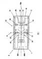
图1示出了应用了本发明的非接触式连接器10的基本构造和结构的一个示例的截面图,该截面图包括旋转轴4。FIG. 1 shows a cross-sectional view of one example of the basic configuration and structure of a
最大组成元件是旋转体1和固定体2;旋转体1配置为能够围绕旋转轴4进行旋转。固定体2设置为一种静止的并且与旋转体1相对的构件。The largest constituent elements are a rotating
旋转体1包括旋转侧构件600、旋转侧电路部11、旋转侧变压器绕组15和旋转侧变压器铁芯(core)16。接下来,固定体2包括固定侧构件601、固定侧电路部21、固定侧变压器绕组25和固定侧变压器铁芯26。The
(2)旋转侧构件600和固定侧构件601的详细构造和功能(2) Detailed structure and function of the rotating
接下来,描述旋转侧构件600和固定侧构件601的详细构造和功能。旋转侧构件600和固定侧构件601如它们的名称所示是旋转侧上的光路构造部件和固定侧上的光路构造部件。Next, detailed configurations and functions of the rotation-
对旋转侧构件600和固定侧构件601的解释从旋转侧椭圆部分反射镜6和安装在固定侧上的椭圆部分反射镜8的类型、功能和结构的解释开始。The explanation of the
(3)椭圆部分反射镜的介绍(3) Introduction of elliptical partial reflector
针对作为三维椭圆状反射体A 500的椭圆体(具有一般光学特征(从该椭圆体的一个焦点发出的光被椭圆体的内表面反射并且会聚在另一个焦点处)的三维椭圆体),图2中(A)示出了与通过仅仅切割该椭圆体的内表面的一部分获得了反射镜面的椭圆部分反射镜8的关系。For an ellipsoid (a three-dimensional ellipsoid with general optical characteristics (light emitted from one focus of the ellipsoid is reflected by the inner surface of the ellipsoid and converges at the other focus) as a three-dimensional ellipsoidal reflector A 500), Fig. (A) in 2 shows the relationship with the elliptical partial reflector 8 in which the reflective mirror surface is obtained by cutting only a part of the inner surface of the ellipsoid.
首先,图2中(B)到图2中(F)的椭圆表示三维椭圆状反射体A 500,其中,F1和F2表示发光侧焦点F1和光接收侧焦点F2;并且图2中(B)到(F)示出了从焦点F1发出的光以及在焦点F2会聚的光的状态,并且表示旋转体1与固定体2之间的边界中心线700的水平实线。在下文中,假定一种状态:F1位于旋转体1一侧上,而F2位于固定体2一侧上。At first, among Fig. 2 (B) to among Fig. 2 (F), the ellipse represents three-dimensional
考虑在三维椭圆状反射体A 500的旋转体1一侧上的椭圆弧旋转时从F1到F2的路径。(实际上,仅仅示出旋转后椭圆弧的图就足够了。)按照被示为旋转轴4的位置的旋转位置,存在五种情况即X到V,如图2中(B)到图2中(F)所示。Consider the path from F1 to F2 as the elliptical arc on the
旋转轴4的位置X:在焦点F1之外-参见图2中(B)。Position X of the axis of rotation 4: outside the focal point F1 - see (B) in FIG. 2 .
旋转轴4的位置Y:在焦点F1-参见图2中(C)。Position Y of the axis of rotation 4: at the focal point F1 - see (C) in FIG. 2 .
旋转轴4的位置Z:在焦点F1与焦点F2之间-参见图2中(D)。Position Z of the axis of rotation 4: between the focal points F1 and F2 - see (D) in FIG. 2 .
旋转轴4的位置U:在焦点F2-参见图2中(E)。Position U of the axis of rotation 4: at the focal point F2 - see (E) in FIG. 2 .
旋转轴4的位置V:在焦点F2之外-参见图2中(F)。Position V of the axis of rotation 4: outside the focal point F2 - see (F) in FIG. 2 .
首先,图2中(B)示出了针对“旋转轴4的位置X”的旋转状态;在该旋转状态下焦点的布置特点使得焦点F1和F2都随着旋转而移动。First, (B) in FIG. 2 shows a rotation state for "the position X of the
如果左侧的椭圆是三维椭圆状反射体A 500,并且右侧的椭圆是旋转后的状态中,则由于F1移动并且F2也移动,所以对于从F1发出的光无法保持椭圆形状并且不能够构成光路。(实际上,仅仅在旋转体1一侧上的椭圆弧旋转,因此仅需要绘制旋转后的椭圆弧;但是为了阐明椭圆的旋转,绘制了整个椭圆形状)If the ellipse on the left is a three-dimensional
接下来,在图2的(C)中示出了针对“旋转轴4的位置Y”的旋转状态。在该旋转状态下,布置特点使得:在F2随着旋转而移动的同时,F1是静止的。在这种情况下,如图2中(C)所示,如果安装了椭圆部分反射镜8,则F2的移动被吸收,并且总能够构成椭圆体。Next, the rotation state with respect to the "position Y of the
也就是说,即使在旋转的过程中,仍能够构成三维椭圆状反射体A500的从F1到F2的光路。在这种情况下,椭圆部分反射镜8的形状存在两种类型:片段形状(section shape)(左侧所示)和椭圆环形(右侧所示)。That is to say, even in the process of rotation, the optical path from F1 to F2 of the three-dimensional elliptical reflector A500 can still be formed. In this case, there are two types of shapes of the elliptical partial reflection mirror 8: a section shape (shown on the left) and an elliptical ring shape (shown on the right).
图2中(D)示出了针对“旋转轴4的位置Z”的旋转状态;在该旋转状态下,与图2中(B)的情况相似,布置特点使得:F2随着旋转而移动,并且F1也移动。由于F1和F2都移动,所以对于从F1发出的光无法保持椭圆形状,并且无法构成光路。(D) in FIG. 2 shows a rotation state for "the position Z of the
在图2的(E)中,示出了针对“旋转轴4的位置U”的旋转状态;在该旋转状态下,布置特点使得:在旋转过程中F1移动,而F2是静止的。在这种情况下,如图2的(E)所示,存在椭圆部分反射镜8的两个安装位置,即在旋转体1一侧上和在固定体2一侧上。首先,考虑固定体2一侧,如果以旋转轴4为中心轴的截面是环形反射镜,则F1的移动被吸收,并且总能够构成椭圆体。接下来,在安装在旋转体1一侧上的情况下,即使椭圆部分反射镜8的形状是片段状,仍然能够总构成椭圆体。也就是说,在这种情况下,能够构成三维椭圆状反射体A 500的从F1到F2的光路。In (E) of FIG. 2 , a rotation state for "the position U of the
最后,在图2的(F)中示出了针对“旋转轴4的位置V”情况下的旋转状态;与图2的(B)相似,针对该旋转状态的布置特点使得:F1随旋转而移动,并且F2也移动。Finally, in (F) of Fig. 2 is shown the rotation state for the case of "the position V of the
另外,在这种情况下,与图2的(B)相似,对于从F1发出的光无法保持椭圆形状,并且不能够构成光路。Also, in this case, similarly to (B) of FIG. 2 , the elliptical shape cannot be maintained for the light emitted from F1, and an optical path cannot be constituted.
(4)仅仅存在三种类型的椭圆部分反射镜(4) There are only three types of elliptical partial reflectors
以上内容能够总结为如下:The above can be summarized as follows:
★存在两种形状的椭圆部分反射镜8,即,片段状和椭圆环形;There are two shapes of elliptical partial reflectors 8, namely segmental and elliptical ring;
★存在如下的A、B、C和D的三种类型的利用椭圆部分反射镜8从旋转体1到固定体2构成的光路:★There are three types of optical paths A, B, C and D as follows:

需要对在以上表中使用的表述进行两点补充。Two additions need to be made to the expressions used in the table above.
第一点是关于“发光源”;在这个表中,“发光源”是指光发射元件、光纤的发光点、或者从光发射元件或从光纤发出的光的会聚点。The first point is about "light emitting source"; in this table, "light emitting source" refers to a light emitting element, a light emitting point of an optical fiber, or a converging point of light emitted from a light emitting element or from an optical fiber.
第二点关注“在旋转轴4之外”与“在旋转轴4上”之间的差别。前者“在旋转轴4之外”是指“在除了在旋转轴4上以外的位置也能够安装”。另一方面,后者“在旋转轴4上”是指“仅仅能够安装在旋转轴4上的位置”。换言之,前者情况与后者情况相比,在选择安装位置方面有更大自由度,并且“在旋转轴4之外”包括“在旋转轴4上”。因此,“在旋转轴4上”的位置是“在旋转轴4之外”的特殊情况。The second point concerns the difference between "outside the axis of
最后,可以看出:在椭圆部分反射镜8中,可以说,关于发光源和光接收元件的安装位置,椭圆环形反射镜比圆环形反射镜能够提供更大的光路构造自由度。然而,由于难于进行制造,所以在设计阶段必须全面考虑是要利用椭圆环形反射镜还是利用片段形状反射镜。Finally, it can be seen that in the elliptical partial reflector 8, it can be said that the elliptical annular reflector can provide a greater degree of freedom in optical path configuration than the circular annular reflector with regard to the installation positions of the light emitting source and the light receiving element. However, due to the difficulty in manufacturing, it is necessary to fully consider whether to use an elliptical ring mirror or a segment-shaped mirror at the design stage.
(5)存在三种多通道设计的方法,但是最终存在两种方法(5) There are three methods of multi-channel design, but ultimately there are two methods
接下来,考虑利用以上椭圆部分反射镜8的多通道设计。多通道设计需要在旋转体1与固定体2之间构建多个光路,并且由此利用椭圆部分反射镜8的多通道设计需要利用在上表中所示的组成光路A、组成光路B、组成光路C或者组成光路D构建多个光路。然后,构造方法如下:Next, consider a multi-channel design utilizing the elliptical partial mirror 8 above. The multi-channel design needs to build multiple optical paths between the
★利用多个椭圆片段形状反射镜的情况★The case of using multiple elliptical segment shape mirrors
#1:通过在旋转轴4上层叠多个片段形状反射镜构建多个组成光路A;#1: Construct multiple component light paths A by stacking multiple segment-shaped mirrors on the
#2:通过在旋转轴4上层叠多个光接收元件构建多个组成光路B;#2: Construct a plurality of component light paths B by stacking a plurality of light receiving elements on the
#3:通过组合组成光路A和组成光路B构建多个(仅两个)光路;#3: Construct multiple (only two) light paths by combining composition light path A and composition light path B;
★利用多个椭圆环形反射镜的情况★When using multiple elliptical ring mirrors
#1:通过在旋转轴4上层叠多个椭圆环形反射镜构建多个组成光路C;#1: Construct multiple optical paths C by stacking multiple elliptical annular mirrors on the
★利用多个圆环形反射镜的情况★Using multiple circular mirrors
#1:通过在旋转轴4上层叠多个圆环形反射镜构建多个组成光路D。#1: Construct multiple component light paths D by stacking multiple annular mirrors on the
清楚的是,还存在组合多个椭圆片段形状反射镜、多个椭圆环形反射镜或者多个圆环形反射镜的构造方法;然而,描述了利用单独椭圆片段形状反射镜、单独椭圆环形反射镜或者单独圆环形反射镜的第一构造方法。Clearly, there are also construction methods combining multiple elliptical segment shape mirrors, multiple elliptical ring mirrors, or multiple toroidal mirrors; Or the first construction method of a single donut-shaped reflector.
(6)在利用椭圆片段形状反射镜的情况下,最多是两个通道(6) In the case of using elliptical segment shape mirrors, up to two channels
当在多通道设计中应用椭圆片段形状反射镜时,实际上,#1和#2是无法实现的,而#3是可实现的。When applying elliptical segment shape mirrors in a multi-channel design, #1 and #2 are practically impossible, while #3 is achievable.
图3中(A)到(D)示出了为什么#1和#2是无法实现的;光路阻塞的现象是相同的。图3中(A)和图3中(B)示出了在安装有两个层叠的片段形状反射镜的结构的两个示例。图3中(A)示出了利用透明保持构件将下侧片段形状反射镜安装在上侧片段形状反射镜上的状态。如果能够正确地设计透射特征和其它光学特征以及结构强度,则利用这个透明构件的保持方法也不是不可能的,但是由于是在保持构件没有光路阻塞的前提下提出的光路构造,所以这里不考虑利用这种透明构件的保持方法。图3中(B)示出了一种下侧片段形状反射镜通过上侧片段形状反射镜中的中心孔安装在固定体2上(或者旋转体1上)的状态。在这种情况下,由上侧片段形状反射镜所反射的光的光路被穿透式保持构件(虚线)阻挡,从而出现光路被中断的位置。(A) to (D) in Fig. 3 show why #1 and #2 cannot be realized; the phenomenon of optical path blocking is the same. FIG. 3(A) and FIG. 3(B) show two examples of a structure in which two stacked segment-shaped mirrors are mounted. FIG. 3(A) shows a state where the lower segment-shaped mirror is attached to the upper segment-shaped mirror by using a transparent holding member. If the transmission features and other optical features and structural strength can be properly designed, it is not impossible to use the holding method of this transparent member, but since the optical path structure is proposed under the premise that the holding member does not block the optical path, it is not considered here A holding method of such a transparent member is utilized. (B) in FIG. 3 shows a state where the lower segment-shaped reflector is mounted on the fixed body 2 (or the rotating body 1 ) through the central hole in the upper segment-shaped reflector. In this case, the optical path of the light reflected by the segment-shaped mirror on the upper side is blocked by the penetrating holding member (dotted line), so that a position where the optical path is interrupted occurs.
接下来,图3中(C)示出了一种层叠并且安装有两个光接收元件的结构。在这种情况下,下侧光接收元件必须总是通过透明保持构件安装在上侧光接收元件上,使得至下侧光接收元件的输入/输出布线是必须的,并且以保持构件不会产生光路阻塞为前提的光路构成也是不可能的。Next, (C) in FIG. 3 shows a structure in which two light-receiving elements are stacked and mounted. In this case, the lower light-receiving element must always be mounted on the upper light-receiving element through the transparent holding member, so that input/output wiring to the lower light-receiving element is necessary, and the holding member does not produce It is also impossible to configure the optical path on the premise of optical path blocking.
图3中(D)示出了在一行中排列以确保两个通道的两个椭圆片段形状反射镜的布置的示例。因为显然没有由于保持构件引起的阻塞现象,所以这与图3的(A)和(B)中多个片段反射镜层叠安装的情况不同,从而该方法可用于构造两个通道。然而,对于中心反射镜和周边反射镜,反射角特点不同,并且无法确保两个组成光路A等同,并且由此这里没有采用这种方法。(下面讨论等同。)(D) in FIG. 3 shows an example of the arrangement of two elliptical segment-shaped mirrors arranged in a row to secure two channels. This is different from the case where a plurality of segment mirrors are stacked in (A) and (B) of FIG. 3 because there is apparently no clogging phenomenon due to the holding member, so that this method can be used to construct two channels. However, the reflection angle characteristics are different for the central and peripheral mirrors, and it is not possible to ensure that the two constituent optical paths A are equal, and thus this approach is not taken here. (Equivalents are discussed below.)
基于以上内容,总结出:当利用椭圆片段形状反射镜以形成多通道时,最大数目是两个通道。(对于#1或者对于#2不能够实现多通道,并且由此仅可以实现这两种情况的组合。)Based on the above, it is concluded that when using elliptical segment shape mirrors to form multiple channels, the maximum number is two channels. (Multi-passing is not possible for #1 or for #2, and thus only a combination of these two cases is possible.)
(7)在椭圆环形反射镜的情况下,可以实现三个通道或者更多通道(7) In the case of an elliptical annular mirror, three or more channels can be realized
接下来,在利用椭圆环形反射镜形成多通道的情况中,可以使用构造方法#1(通过在旋转轴4上层叠多个环形反射镜形成多个组成光路C)。Next, in the case of forming multiple channels using an elliptical annular mirror, configuration method #1 (forming a plurality of constituent optical paths C by laminating a plurality of annular mirrors on the rotation axis 4 ) can be used.
(8)当利用圆环形反射镜时,不能够实现多通道设计(8) Multi-channel design cannot be achieved when using circular mirrors
接下来,当尝试利用圆环形反射镜设计多通道时,光接收元件层叠在旋转轴4上,并且由此由于在图3的(C)中所解释的原因(无法实现多个光接收元件的层叠隔离)不能够实现这种设计。利用圆环形反射镜仅仅能够构造单通道。Next, when trying to design a multi-channel using a donut-shaped mirror, the light-receiving element is stacked on the
(9)组成光路A的椭圆光学系统的结构和功能(9) The structure and function of the elliptical optical system making up the optical path A
本发明提出了采用椭圆部分反射镜的多通道非接触式连接器10;为了引入这种连接器,首先解释形成组成光路A的光学系统的构造和功能。The present invention proposes a multi-channel
在图4的(A)到(E)中示出了组成光路A的光路构造。The optical path configuration constituting the optical path A is shown in (A) to (E) of FIG. 4 .
首先,图4的(A)示出了从旋转侧到固定侧的单向通信系统。First, (A) of FIG. 4 shows a one-way communication system from the rotating side to the fixed side.
利用三维椭圆状反射体A 500的内表面作为反射镜面,旋转侧光发射元件A 13和固定侧光接收元件A 24容纳其中,并且采用三维椭圆状反射体A 500的闭曲面(closed surface)的一部分作为固定侧椭圆片段反射镜A 81。The inner surface of the three-dimensional
当然,该功能是从旋转侧到固定侧的光路构造的功能;在该附图中,示出了一个示例性状态,为了附图的简洁,在该示例性状态中作为发光源的旋转侧光发射元件A 13直接安装在三维椭圆状反射体A 500的多个发光侧焦点F1 3其中之一上。Of course, this function is a function of the optical path configuration from the rotating side to the fixed side; The emitting element A13 is directly installed on one of the multiple light emitting side focal points F13 of the three-dimensional elliptical reflector A500.
接下来,图4中(B)示出了阐述旋转侧光发射元件A 13、固定侧光接收元件A 24和固定侧椭圆片段反射镜A 81的安装位置的整体结构。Next, (B) in FIG. 4 shows an overall structure illustrating the installation positions of the rotating side light emitting
在这种结构中,旋转侧光发射元件A 13安装在旋转体1上,并且固定侧光接收元件A 24和固定侧椭圆片段反射镜A 81安装在固定体2上。In this structure, the rotating side light emitting element A13 is installed on the
接下来,图4中(C)示出了从旋转侧到固定侧的单向通信系统。利用三维椭圆状反射体B 501的内表面作为反射镜面,固定侧光发射元件A23和旋转侧光接收元件A 14容纳其中,并且采用三维椭圆状反射体B 501的闭曲面的一部分作为旋转侧椭圆片段反射镜A 61。Next, (C) in FIG. 4 shows a one-way communication system from the rotating side to the fixed side. The inner surface of the three-dimensional elliptical reflector B501 is used as a reflective mirror, and the fixed-side light-emitting element A23 and the rotating-side light-receiving element A14 are accommodated therein, and a part of the closed surface of the three-dimensional elliptical reflector B501 is used as the rotating-side ellipse
当然,这个功能是从固定侧到旋转侧的光路构造的功能;在该附图中,示出了一个示例性状态,为了附图的简洁,在该示例性状态中作为发光源的固定侧光发射元件A 23直接安装在三维椭圆状反射体B 501的多个发光侧焦点其中之一上。Of course, this function is a function of the optical path configuration from the fixed side to the rotating side; The emitting
接下来,图4中(D)示出了阐述固定侧光发射元件A 23、旋转侧光接收元件A 14和旋转侧椭圆片段反射镜A 61的安装位置的整体结构。Next, (D) in FIG. 4 shows the overall structure illustrating the installation positions of the fixed-side light-emitting
在这个结构中,固定侧光发射元件A 23安装在固定体2上,并且旋转侧光接收元件A 14和旋转侧椭圆片段反射镜A 61安装在旋转体1上。In this structure, the fixed-side light emitting
最后,图4中(E)示出了形成非接触式连接器10的光学系统的旋转侧构件600和固定侧构件601的构成、功能和结构。Finally, (E) in FIG. 4 shows the composition, function, and structure of the rotation-
首先,旋转侧构件600包括安装在旋转体1上的旋转侧光发射元件A 13、旋转侧椭圆片段反射镜A 61和旋转侧光接收元件A 14。如上所解释的,旋转侧光发射元件A 13是照字面意思具有从旋转侧发光功能的元件;旋转侧椭圆片段反射镜A 61和旋转侧光接收元件A 14是“安装在旋转侧上”并且具有“接收来自固定侧信号的功能”。First, the
固定侧构件601包括安装在固定体2上的固定侧光发射元件A 23、固定侧椭圆片段反射镜A 8和固定侧光接收元件A 24。然而,这种情况下的构造和功能与上述旋转侧构件600相似,并且由此省去了解释。The fixed-
接下来,从图4中(E)清楚地看出,该结构使得:旋转侧构件600安装在旋转体1的旋转轴4的轴端位置中,而固定侧构件601也以相对的状态安装在固定体2的旋转轴4的轴端位置中。Next, as can be clearly seen from (E) in FIG. 4 , the structure is such that the
(10)DL系统和UL系统的定义(10) Definition of DL system and UL system
利用图4中(E),可以清楚地定义通信系统。Using (E) in Fig. 4, the communication system can be clearly defined.
★从旋转侧到固定侧的通信系统:是指从旋转侧构件600到固定侧构件601的通信系统,下文称作下行链路系统并且缩写为DL系统。★Communication system from rotating side to fixed side: refers to a communication system from rotating
★从固定侧到旋转侧的通信系统:是指从固定侧构件601到旋转侧构件600的通信系统,下文称作上行链路系统并且缩写为UL系统。★Communication system from fixed side to rotating side: refers to the communication system from the fixed
(11)组成光路B和组成光路C(11) Composition of light path B and composition of light path C
在上文中解释了组成光路A的细节,并且由此解释了其余组成光路B和组成光路C的细节;然而,该构造方法与组成光路A的情况相同。如上所述,利用圆环形反射镜的组成光路D不能够被构造成利用单圆环形反射镜的多通道系统,并且由此在下文中排除了该组成光路D。The details of the constituent light path A are explained above, and thus the remaining details of the constituent light path B and the constituent light path C are explained; however, the construction method is the same as in the case of the constituent light path A. As mentioned above, the component beam path D using a donut mirror cannot be configured as a multi-channel system using a single donut mirror and is therefore excluded hereinafter.
组成构件的安装位置可以概括如下:The installation positions of the components can be summarized as follows:
★组成光路A:光源在旋转轴上,片段反射镜在旋转轴上,光接收元件在旋转轴之外;★ Composition of optical path A: the light source is on the rotation axis, the segment mirror is on the rotation axis, and the light receiving element is outside the rotation axis;
★组成光路B:光源在旋转轴之外,片段反射镜在旋转轴之外,光接收元件在旋转轴上;★ Composition of optical path B: the light source is outside the rotation axis, the fragment reflector is outside the rotation axis, and the light receiving element is on the rotation axis;
★组成光路C:光源在旋转轴之外,环形反射镜在旋转轴上,光接收元件在旋转轴之外。★Composition optical path C: the light source is outside the rotation axis, the annular reflector is on the rotation axis, and the light receiving element is outside the rotation axis.
图5示出了组成光路B,作为发光源设置在旋转轴4上的构造的示例以及作为上表的补充点的“在旋转轴4之外包括在旋转轴4上的情况”的示例。在图5中,示出了一种DL系统,其包括固定侧光接收元件B 241以及安装在旋转体1上的旋转侧光发射元件B 131和旋转侧椭圆片段反射镜B 62。FIG. 5 shows an example of a configuration in which the optical path B is composed as a light emitting source provided on the
接下来,图6示出了组成光路C。Next, FIG. 6 shows the composition optical path C. As shown in FIG.
图6中也示出了一种DL系统,其包括固定侧椭圆环形反射镜A 91和固定侧光接收元件A 24以及安装在旋转体1上的旋转侧光发射元件A13。Also shown in FIG. 6 is a DL system, which includes a fixed-side elliptical
(12)名称含义的解释(12) Explanation of the meaning of the name
这里,将阐述组成部件的名称的含义。这些是包含在旋转侧光发射元件、固定侧光接收元件以及其它名称中的“旋转侧”和“固定侧”的含义。Here, the meaning of the names of the constituent parts will be explained. These are the meanings of "rotating side" and "fixed side" included in the rotating-side light-emitting element, fixed-side light-receiving element, and other names.
本发明的主要点在于:光路被构造为使得来自旋转侧光发射元件A13的发光信号被固定侧光接收元件A 24接收,并且进而光路被构造为使得来自固定侧光发射元件A 23的发光信号被旋转侧光接收元件A 14接收。于是,旋转侧光发射元件中的“旋转侧”是指“安装在旋转侧上”,并且另外,固定侧光接收元件A 24中的“固定侧”是指“安装在固定侧上”。The main point of the present invention is that the optical path is constructed so that the light emitting signal from the rotating side light emitting element A13 is received by the fixed side light receiving element A24, and then the light path is constructed so that the light emitting signal from the fixed side light emitting element A23 Received by the rotating side light receiving element A14. Then, "rotation side" in the rotation side light emitting element means "mounted on the rotation side", and further, "fixed side" in the fixed side light receiving element A24 means "mounted on the fixed side".
也就是说,名称是下述前提进行分配的:构造不会被执行为使得:来自旋转侧光发射元件A 13的发光信号被旋转侧光接收元件A 14接收或者来自固定侧光发射元件A 23的发光信号被固定侧光接收元件A 24接收。That is to say, the name is assigned on the premise that the construction will not be performed such that: the light emitting signal from the rotating side light emitting
(13)上行链路系统(固定侧→旋转侧)的构建方法(13) Construction method of uplink system (fixed side → rotating side)
在图4中(E)的解释中,解释了这样一种结构:以相对的状态安装旋转侧构件600和固定侧构件601;但是实际上,该图是按旋转侧构件600和固定侧构件601关于边界中心线700对称的结构绘制的。In the explanation of (E) in FIG. 4 , such a structure is explained that the
这是因为提出了一种UL系统和DL系统的旋转运动被认为是相对运动关系的光路构造方法。This is because an optical path construction method is proposed in which the rotational motion of the UL system and the DL system is considered as a relative motion relationship.
DL系统是处于旋转侧旋转而固定侧静止的状态的通信系统,并且DL系统是通信仅仅来自固定侧的通信系统。The DL system is a communication system in a state where the rotating side rotates and the fixed side is stationary, and the DL system is a communication system in which communication comes only from the fixed side.
从“固定侧旋转而旋转侧静止的状态”的相对运动的观点来看,这个DL系统是通信仅仅来自旋转侧的通信系统。This DL system is a communication system in which communication comes only from the rotating side from the viewpoint of relative motion of "a state where the fixed side rotates and the rotating side is stationary".
也就是说,UL系统和DL系统可以具有相同结构。That is, the UL system and the DL system may have the same structure.
例如,图4中(B)示出了旋转侧光发射元件A 13旋转而固定侧椭圆片段反射镜A 81和固定侧光接收元件A 24静止的状态;然而,这也能够看作是旋转侧光发射元件A 13静止而固定侧椭圆片段反射镜A 81和固定侧光接收元件A 24旋转的状态。For example, (B) in FIG. 4 shows a state where the rotating side light emitting
于是,示出了:如果能够构建DL系统,则仅仅通过改变旋转侧和固定侧就可以构建UL系统;以及如果能够构建UL系统,则能够容易地构建DL系统。另外,作为这个构造方法逻辑的结果,也可以应用于多通道系统(当然,如果能够首先构建UL系统,则基于此也能够构建DL系统)。Thus, it was shown that if the DL system can be constructed, the UL system can be constructed only by changing the rotating side and the fixed side; and if the UL system can be constructed, the DL system can be easily constructed. In addition, as a result of the logic of this construction method, it can also be applied to multi-channel systems (of course, if the UL system can be constructed first, the DL system can also be constructed based on this).
(14)双向系统的构建方法(14) Construction method of two-way system
于是,通过关于与旋转轴垂直的面对称地布置DL系统和UL系统并且以相应的椭圆片段反射镜61、81不会重叠的方式组合DL系统和UL系统能够构造双向系统,并且由此该双向系统是非常简单的。Then, a two-way system can be constructed by arranging the DL system and the UL system symmetrically about a plane perpendicular to the rotation axis and combining the DL system and the UL system in such a manner that the corresponding elliptical segment mirrors 61, 81 do not overlap, and thus the The two-way system is very simple.
也就是说,在图4的(E)中,以关于与旋转轴垂直的边界线700对称的方式绘制旋转侧构件600和固定侧构件601,从而构造双向系统。That is, in (E) of FIG. 4 , the rotation-
(15)实现模拟通信的条件(15) Conditions for realizing analog communication
将讨论能够实现模拟通信(模拟信号的通信)的非接触式连接器10。当然,模拟通信是以与非接触式连接器10的光发射元件的发光强度成比例(近似地)的方式发送将要被通信的模拟信号的方法。(在数字通信中,关于光接收元件的强度相似并不严格。)The
于是,为了实现模拟通信,需要在旋转运动过程中接收光发射元件(与通信信号的幅度成比例地发光)的基本100%的发光量。Thus, in order to realize analog communication, it is necessary to receive substantially 100% of the light emission amount of the light emitting element (which emits light in proportion to the magnitude of the communication signal) during the rotational movement.
显然,如果能够关于光束的入射直径适当地设计椭圆部分反射镜8的反射镜面,则通过椭圆的会聚作用,能够实现基本100%的光接收,从而通过椭圆部分反射镜8可以实现模拟通信。Apparently, if the mirror surface of the elliptical partial reflector 8 can be properly designed with respect to the incident diameter of the light beam, substantially 100% light reception can be achieved through the converging action of the ellipse, so that analog communication can be realized through the elliptical partial reflector 8 .
另外,实现100%光接收的前提是确保合适的光接收元件;但是,为了合适地使用光接收元件,必须构造能够使由于旋转引起的接收光强度波动减小的光路。这也是提高模拟通信的质量所必需的,并且由此必须设计使在光接收元件上的入射角波动减小的光路。In addition, the prerequisite for achieving 100% light reception is to secure a suitable light receiving element; however, in order to properly use the light receiving element, it is necessary to construct an optical path capable of reducing fluctuations in received light intensity due to rotation. This is also necessary to improve the quality of analog communication, and thus it is necessary to design an optical path that reduces fluctuations in the angle of incidence on the light receiving element.
(16)旋转侧电路部11和固定侧电路部21的解释(16) Explanation of the rotating
接下来,旋转侧电路部11设置在旋转体1上,并且对从安装在旋转侧的各种设备输入的信号进行数据处理。例如,当各种设备是用于图像拍摄的相机时,来自相机的图像信号等被输入到旋转侧电路部11,并且输出使得通过旋转侧光发射元件A 13发出光的电信号。Next, the rotation
另外,为了从固定体2向旋转体1进行通信的目的,旋转侧光接收元件A 14从固定侧光发射元件A 23接收数据,并且将该数据输出到旋转侧电路部11。In addition, for the purpose of communicating from the fixed
接下来,固定侧电路部21设置在固定体2上,并且将从安装有这个非接触式连接器10的机械装置输入的数据输出到固定侧光发射元件A23。Next, the fixed-
另外,为了从旋转体1到固定体2进行通信的目的,由固定侧光接收元件A 24接收到的数据被输入到固定侧电路部21进行处理和输出,并且输出到在安装有这个非接触式连接器10的机械装置,其中,固定体2连接到这个非接触式连接器10。In addition, for the purpose of communicating from the
(17)旋转变压器的解释(17) Explanation of resolver
接下来,旋转侧变压器绕组15安装在旋转体1中与固定体2相对的位置上,并且通过电磁感应作用从固定体2提供电力,从而电力能够通过这些旋转侧变压器绕组15提供给旋转体1的各个部分。Next, the rotating
旋转侧变压器铁芯16形成有U形截面从而包围旋转侧变压器绕组15。旋转侧变压器铁芯16在凹部中容纳旋转侧变压器绕组15,并且与在固定体2一侧的固定侧变压器绕组25和固定侧变压器铁芯26一起形成旋转变压器。The rotary
固定侧变压器绕组25位于固定体2上与旋转侧变压器绕组15相对的位置中。从安装有这个非接触式连接器10的装置向固定侧变压器绕组25供电,其中,固定体2连接到这个非接触式连接器10。The fixed-side transformer winding 25 is located on the
固定侧变压器铁芯26形成有U形截面,从而包围固定侧变压器绕组25。固定侧变压器铁芯26在凹部中容纳固定侧变压器绕组25,并且与在旋转体1一侧的旋转侧变压器绕组15和旋转侧变压器铁芯16一起形成旋转变压器。The fixed-
(18)1通道系统的添加(18) Addition of 1-channel system
在上文中,描述了具有模拟通信功能的双向1通道(下文缩写为“Ch”)系统的光路构造方法。In the foregoing, an optical path configuration method of a bidirectional 1-channel (hereinafter abbreviated as "Ch") system with an analog communication function has been described.
陈述如下:本质是利用椭圆片段反射镜构造DL系统,并且UL系统仅仅需要是DL系统的对称布置。It is stated as follows: The essence is to construct the DL system with elliptical segment mirrors, and the UL system only needs to be a symmetrical arrangement of the DL system.
在上述内容中,采用组成光路A、组成光路B或者组成光路C作为DL系统(或者UL系统)通过对称布置构造双向1通道系统;但是,由于这仅仅是双向1通道系统的构建,所以可以通过非对称布置的构造方法容易地构建双向系统,例如当DL系统是组成光路A并且UL系统是组成光路B时。应该根据实际设计需求进行选择。In the above content, the component optical path A, the component optical path B, or the component optical path C are used as the DL system (or UL system) to construct a bidirectional 1-channel system through a symmetrical arrangement; however, since this is only the construction of a bidirectional 1-channel system, it can be achieved by The construction method of the asymmetric arrangement easily constructs a bidirectional system, for example, when the DL system is composed of light path A and the UL system is composed of light path B. It should be selected according to the actual design requirements.
(19)确保多通道模拟通信中的多个通道之间一致性的条件的添加(19) Addition of conditions to ensure consistency between multiple channels in multi-channel analog communication
不言而喻,1通道系统是指从一个光发射元件到一个光接收元件的通信系统。于是,多通道系统是指从多个光发射元件到多个光接收元件的通信系统。在下文中,讨论具有模拟通信功能的双向多通道系统的光路构造。It goes without saying that the 1-channel system refers to a communication system from one light-emitting element to one light-receiving element. Thus, a multi-channel system refers to a communication system from a plurality of light-emitting elements to a plurality of light-receiving elements. In the following, the optical path configuration of a two-way multi-channel system with analog communication functions is discussed.
首先,为了获得具有模拟通信功能的多通道非接触式连接器10,对于提高便利性来说“确保多个通道之间一致性”是重要的。First, in order to obtain the multi-channel
这是因为如果多个通道的特征不同,则不能够确保线路信号的质量。为此,首先需要以使得多个通道之间的光接收特征的差别较小的方式构造实现了多个组成光路的多通道DL系统。This is because the quality of the line signal cannot be ensured if the characteristics of the plurality of channels are different. For this reason, it is first necessary to configure a multi-channel DL system implementing a plurality of constituent light paths in such a manner that the difference in light-receiving characteristics among the plurality of channels is small.
(20)所需的用于模拟通信的非接触式连接器的总结(20) Summary of required contactless connectors for analog communication
对以上内容进行总结可以看出,为了构造具有模拟通信功能的多通道DL系统:Summarizing the above content, it can be seen that in order to construct a multi-channel DL system with analog communication functions:
★在采用椭圆片段反射镜的情况下,★In the case of using elliptical segment mirrors,
使用#3,组成光路A和组成光路B的组合(仅仅两个),以及Using #3, a combination of make-up lightpath A and make-up lightpath B (just two), and
★在采用椭圆环形反射镜的情况下,★In the case of using an elliptical annular reflector,
使用#1,通过在旋转轴4上层叠多个环形反射镜所获得的多个组成光路C。Using #1, a plurality of constituent optical paths C obtained by laminating a plurality of annular mirrors on the
这意味着:利用椭圆片段反射镜能够针对最多高达2通道构造具有模拟通信功能的多通道非接触式连接器10,并且利用椭圆环形反射镜能够针对3个或更多通道构造具有模拟通信功能的多通道非接触式连接器10。This means that a multi-channel
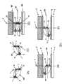
图7示出了椭圆片段反射镜的情况的构造示例,而图8示出了椭圆环形反射镜的情况的构造示例。FIG. 7 shows a configuration example in the case of an elliptical segment mirror, and FIG. 8 shows a configuration example in the case of an elliptical ring mirror.
在这两种情况下,为了以使得在多个通道中光接收特征之间的差别较小的方式构造光路,椭圆片段反射镜的类型被制成相同,并且还采用从相同椭圆体截取的椭圆片段反射镜。In both cases, in order to configure the light path in such a way that the difference between the light-receiving characteristics in multiple channels is small, the type of elliptical segment mirror is made the same, and an ellipse cut from the same ellipsoid is also used Fragment mirror.
图7示出了2通道DL系统。Figure 7 shows a 2-channel DL system.
用于形成2通道DL系统的每个通道的椭圆片段反射镜的类型是具有从相同椭圆体截取的相同形状的相同椭圆片段反射镜。The type of elliptical segment mirror used to form each channel of the 2-channel DL system is the same elliptical segment mirror with the same shape cut from the same ellipsoid.
接下来,图8示出了利用椭圆环形反射镜的3通道的情况,并且图8示出了双向系统。用于形成3通道DL系统的每个通道的椭圆片段反射镜的类型是具有从相同椭圆体截取的相同形状的相同椭圆环形反射镜。Next, FIG. 8 shows a 3-channel case using an elliptical ring mirror, and FIG. 8 shows a two-way system. The type of elliptical segment mirror used to form each channel of the 3-channel DL system is the same elliptical ring mirror with the same shape cut from the same ellipsoid.
首先,DL系统具有下述结构:旋转侧光发射元件A 13、旋转侧光发射元件B 131和旋转侧光发射元件C 132安装在旋转体1上,并且固定侧光接收元件A 24、固定侧光接收元件B 241和固定侧光接收元件C 242以及三个反射镜(即,固定侧椭圆环形反射镜A 91、固定侧椭圆环形反射镜B 92和固定侧椭圆环形反射镜C 93)安装在固定体2上。First, the DL system has the following structure: the rotation-side light-emitting
接下来,UL系统具有下述结构:固定侧光发射元件A 23、固定侧光发射元件B 231和固定侧光发射元件C 232安装在固定体2上,并且旋转侧光接收元件A 14、旋转侧光接收元件B 141和旋转侧光接收元件C142以及三个反射镜(即,旋转侧椭圆环形反射镜A 71、旋转侧椭圆环形反射镜B 72和旋转侧椭圆环形反射镜C 73)安装在旋转体1上。Next, the UL system has the following structure: the fixed-side light-emitting
在以上内容中,描述了利用单独的椭圆片段反射镜和单独的椭圆环形反射镜构造具有模拟通信功能的多通道非接触式连接器10的方法。In the above, the method of constructing the multi-channel
然而,如上所述,还存在组合椭圆片段反射镜、椭圆环形反射镜或者圆环形反射镜的构造方法。However, as described above, there are also construction methods combining elliptical segment mirrors, elliptical ring mirrors, or donut ring mirrors.
在这个构造方法中,针对每个通道所应用的椭圆部分反射镜的形状和类型不同,并且由此“多个通道之间的一致性”的条件被放松。In this construction method, the shape and type of the elliptical partial mirrors applied are different for each channel, and thus the condition of "consistency among multiple channels" is relaxed.
作为一个示例,图9示出了椭圆部分反射镜的类型发生了改变的2通道系统的示例,其中,椭圆部分反射镜为椭圆片段反射镜和椭圆环形反射镜。在多个通道之间在光接收元件上的入射特征的一致性的需求被放松,并且由此在构造光路方面存在更大的自由度。As an example, FIG. 9 shows an example of a 2-channel system in which the types of elliptical partial reflectors are changed, where the elliptical partial reflectors are elliptical segment mirrors and elliptical ring mirrors. The requirement for uniformity of the incidence characteristics on the light receiving element between multiple channels is relaxed, and thus there is greater freedom in configuring the light path.
最后,讨论圆环形反射镜。圆环形反射镜的特征与用于组成光路B的椭圆片段反射镜的特征相似,这是因为光接收元件需要设置在旋转轴4上。Finally, a discussion of donut mirrors. The features of the circular ring mirror are similar to those of the elliptical segment mirror used to compose the optical path B because the light receiving element needs to be arranged on the
然而,与椭圆片段反射镜相比较而言制造性较差,并且此外存在光接收元件上的入射角变窄的趋势,从而没有频繁地利用这种反射镜。于是,有利的是利用采用了椭圆片段反射镜的组成光路B构成多通道系统,而不是利用采用了圆环形反射镜的组成光路D来构成多通道系统。于是,这里没有呈现特定构造示例。However, manufacturability is poor compared with elliptical segment mirrors, and furthermore, there is a tendency for the incident angle on the light receiving element to be narrowed, so that such mirrors are not frequently utilized. Thus, it is advantageous to form a multi-channel system with the component beam path B using elliptical segment mirrors, rather than using the component beam path D with donut-shaped mirrors. Thus, no specific configuration example is presented here.
另外,响应于对于非接触式连接器10小型化的要求,针对在每个通道中使用的小型化椭圆片段反射镜的规范变得更加严格,并且存在下述情况:已经变得需要放松100%接收入射光束的规范并且放松多个部分反射镜的下述规范:对于每个通道该多个部分反射镜是相同类型的椭圆部分反射镜并且来自相同椭圆体。In addition, in response to the request for miniaturization of the
作为一个示例,图10示出了一种在图7的情况下的多个椭圆片段反射镜其中之一被小型化的构造示例。As an example, FIG. 10 shows a configuration example in which one of the plurality of elliptical segment mirrors in the case of FIG. 7 is miniaturized.
在该构造示例中,非接触式连接器10不再能够说在所有通道内都具有模拟通信功能,并且必须说是具有混合信号(模拟信号和数字信号的混合信号)的通信功能的非接触式连接器10,一部分通道用于进行数字通信。In this configuration example, the
在以上内容中,已经描述了利用椭圆部分反射镜实现非接触式连接器10的多通道设计的方法。In the above, the method of realizing the multi-channel design of the
多通道构造方法需要增加包括一个光发射元件→一个椭圆部分反射镜→一个光接收元件的1通道光路的数目,其中,在空间中独立地构建每个光路(由于存在一对一关系,所以光发射元件的数目等于光接收元件的数目)。The multi-channel construction method needs to increase the number of 1-channel optical paths including one light-emitting element → one elliptical partial mirror → one light-receiving element, where each optical path is constructed independently in space (since there is a one-to-one relationship, the light The number of emitting elements is equal to the number of light receiving elements).
另一方面,作为非接触式连接器10的多通道构造方法,还存在采用多个光发射元件→一个椭圆部分反射镜→多个光接收元件的方法(还存在如下情况:光发射元件的数目与光接收元件的数目不同)。在这些情况下,在所发送光信号的调制和解调操作的前提下,这可以称作光学多通道设计方法,其中以使得由椭圆部分反射镜反射的多个光束被多个光接收元件同时接收的方式构造多个光路。(为了强调差别,前者可以称作空间多通道构造方法。)On the other hand, as a multi-channel construction method of the
构造将多个光束从单椭圆部分反射镜反射到多个光接收元件的多个光路意味着:光接收元件安装在除了椭圆部分反射镜的光接收侧焦点F25之外的位置上。Constructing a plurality of light paths reflecting a plurality of light beams from a single elliptical partial reflection mirror to a plurality of light receiving elements means that the light receiving elements are installed at positions other than the light receiving side focal point F25 of the elliptical partial reflection mirror.
在光学方面,这意味着:使得光接收侧焦点F25之前或之后的光路光束入射在光接收元件上。In terms of optics, this means: making the optical path light beams before or after the light-receiving side focal point F25 incident on the light-receiving element.
图11示出了对于1通道系统通过采用光学多通道方法构造2通道系统的示例。FIG. 11 shows an example of constructing a 2-channel system by employing an optical multi-channel method for a 1-channel system.
从图11可以看出,这个光学多通道设计方法也是基于1通道光学系统的,并且能够称作这样一种多通道设计方法:在单通道光学系统,利用具有宽光接收范围光接收元件对信号进行复用,或者利用针对光接收元件的光学滤波器、用于发送光学信号的编码方法或者其它通道识别手段对信号进行复用。As can be seen from Figure 11, this optical multi-channel design method is also based on a 1-channel optical system, and can be called such a multi-channel design method: in a single-channel optical system, the signal is detected by using a light receiving element with a wide light receiving range Multiplexing, or multiplexing the signals using optical filters for light receiving elements, encoding methods for transmitting optical signals, or other channel identification means.
在以上内容中,讲述了:在椭圆部分反射镜的光接收焦点F25之前或之后的光束被输入到光接收元件光路的构造方法是用于多通道设计的方法;但是,该构造方法出能够应用于针对1通道系统的光路构造。In the above, it has been described that the construction method in which the light beam is input to the light path of the light receiving element before or after the light receiving focus F25 of the elliptical partial reflection mirror is a method for multi-channel design; however, this construction method cannot be applied For the optical path structure of 1-channel system.
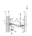
图12示出了对于1通道系统“发光源”的位置移动到发光侧焦点F13之前的光路的一个示例。“发光源”的位置是在除了椭圆部分反射镜的发光侧焦点F13之外的位置,从而光不再会聚在光接收侧焦点F25;而是光束在光接收侧焦点F25处变宽。也就是说,如果以使得“发光源”位置是使得光束直径能够被光接收元件接收的位置的方式进行设计,则能够构造1通道系统光路。该光路构造方法对于放松非接触式连接器10的光学系统的制造精度也是有用的。FIG. 12 shows an example of the optical path before the position of the "light emitting source" is moved to the light emitting side focus F13 for a 1-channel system. The position of the "light-emitting source" is at a position other than the light-emitting-side focus F13 of the elliptical partial reflector, so that light no longer converges at the light-receiving-side focus F25; That is, if it is designed such that the "light emitting source" position is such that the beam diameter can be received by the light receiving element, it is possible to configure a 1-channel system optical path. This optical path configuration method is also useful for relaxing the manufacturing precision of the optical system of the
已经分析了用于构造多通道并发双向通信系统的方法;这里,考虑“并发性”。“并发性”是“能够实现来自旋转侧和来自固定侧的同时通信的性能”。A method for constructing a multi-channel concurrent two-way communication system has been analyzed; here, "concurrency" is considered. "Concurrency" is "capable of enabling simultaneous communication from the rotating side and from the fixed side".
如果作为用于多通道DL系统(或者用于多通道UL系统)的对称结构,执行多通道UL系统(或者多通道DL系统)的构造,则没有阻挡光路的构件,因此出现从多个光发射元件发出并且在多条光路上传播的并发双向光发射,并且双向光被多个光接收元件同时接收。也就是说,如果对称地组合DL系统和UL系统以构造双向系统,则能够确保“并发性”。If the configuration of the multi-channel UL system (or the multi-channel DL system) is performed as a symmetrical structure for the multi-channel DL system (or for the multi-channel UL system), there is no member blocking the light path, and thus there occurs emission from multiple Concurrent bi-directional light emitted by the element and propagated on multiple optical paths is emitted, and the bi-directional light is simultaneously received by multiple light-receiving elements. That is, if the DL system and the UL system are symmetrically combined to construct a bidirectional system, "concurrency" can be ensured.
接下来,图13用于解释从固定体2到旋转体1的非接触式供电。Next, FIG. 13 is used to explain contactless power supply from the fixed
如上所述,旋转侧变压器绕组15缠绕在旋转体1的旋转侧变压器铁芯16的主体部分上,并且固定侧变压器绕组25缠绕在固定体2的固定侧变压器铁芯26的主体部分上。在这种状态下,通过经由固定侧变压器绕组25从安装有这个非接触式连接器10的装置传递电源电流,首先在固定侧变压器铁芯26的周围产生磁场。接下来,由于旋转侧变压器铁芯16与产生磁场的固定侧变压器铁芯26相对地设置,所以形成了磁路,并且在缠绕在主体部分上的旋转侧变压器绕组15中出现电流(由于所谓的电磁感应定律)。通过这种方法,给旋转体1供电,并且例如旋转侧电路部11被驱动,从而能够使得旋转侧光发射元件A 13发出光。As described above, the rotary side transformer winding 15 is wound on the main portion of the rotary
在上述示例中,基于利用旋转侧光发射元件A 13、固定侧光接收元件A 24和椭圆片段反射镜8形成1通道DL系统光路的示例进行了解释;然而,旋转侧光发射元件A 13和固定侧光接收元件A 24能够用光纤代替,以形成在固定侧光纤与旋转侧光纤之间未中断的光路。In the above example, the explanation was made based on the example in which the optical path of the 1-channel DL system is formed using the rotating side light emitting
当然,多条光纤之间的多通道并发双向通信也是可实现的。Of course, multi-channel concurrent bidirectional communication between multiple optical fibers is also achievable.
Claims (8)
Translated fromChineseApplications Claiming Priority (3)
| Application Number | Priority Date | Filing Date | Title |
|---|---|---|---|
| JP2008208422AJP4723621B2 (en) | 2008-08-13 | 2008-08-13 | Non-contact connector |
| JP2008208422 | 2008-08-13 | ||
| JP2008-208422 | 2008-08-13 |
Publications (2)
| Publication Number | Publication Date |
|---|---|
| CN101651034A CN101651034A (en) | 2010-02-17 |
| CN101651034Btrue CN101651034B (en) | 2013-01-02 |
Family
ID=41351933
Family Applications (1)
| Application Number | Title | Priority Date | Filing Date |
|---|---|---|---|
| CN2009101299522AExpired - Fee RelatedCN101651034B (en) | 2008-08-13 | 2009-04-10 | Non-contact connector |
Country Status (6)
| Country | Link |
|---|---|
| US (1) | US7885495B2 (en) |
| EP (1) | EP2154801A3 (en) |
| JP (1) | JP4723621B2 (en) |
| KR (1) | KR101030817B1 (en) |
| CN (1) | CN101651034B (en) |
| IL (1) | IL196954A0 (en) |
Families Citing this family (5)
| Publication number | Priority date | Publication date | Assignee | Title |
|---|---|---|---|---|
| US8934776B2 (en)* | 2010-04-09 | 2015-01-13 | Bae Systems Information And Electronic Systems Integration Inc. | Wireless data interface with multiple, independent transmission sources |
| US9143227B2 (en)* | 2011-11-07 | 2015-09-22 | Ciena Corporation | Optical transport network port protection systems and methods using flexible switch criteria |
| JP5841665B2 (en)* | 2012-08-24 | 2016-01-13 | 中部日本マルコ株式会社 | Non-contact connector |
| US10113837B2 (en) | 2015-11-03 | 2018-10-30 | N2 Imaging Systems, LLC | Non-contact optical connections for firearm accessories |
| US11143838B2 (en) | 2019-01-08 | 2021-10-12 | N2 Imaging Systems, LLC | Optical element retainers |
Citations (3)
| Publication number | Priority date | Publication date | Assignee | Title |
|---|---|---|---|---|
| US4900117A (en)* | 1989-02-21 | 1990-02-13 | Chen Linus T | Rotary optical coupler utilizing cylindrical ringshaped mirrors and method of making same |
| US5319726A (en)* | 1993-09-30 | 1994-06-07 | The United States Of America As Represented By The Secretary Of The Navy | Multi-line passive fiber optic slipring |
| CN1813501A (en)* | 2003-06-30 | 2006-08-02 | 阿斯波康普科技公司 | Method for transmission of signals in a circuit board and a circuit board |
Family Cites Families (10)
| Publication number | Priority date | Publication date | Assignee | Title |
|---|---|---|---|---|
| US5436988A (en)* | 1994-01-13 | 1995-07-25 | Mechanical Technology Inc. | Optical slip ring |
| JP2000111718A (en)* | 1998-09-30 | 2000-04-21 | Sanyo Electric Co Ltd | Optical reflection body and optical transmitting device |
| JP3741608B2 (en)* | 1999-12-17 | 2006-02-01 | シャープ株式会社 | Bidirectional optical communication device |
| JP3598053B2 (en) | 2000-08-29 | 2004-12-08 | 多摩川精機株式会社 | Rotary non-contact connector |
| DE10336925B4 (en)* | 2003-08-07 | 2006-01-26 | Schleifring Und Apparatebau Gmbh | Optical rotary transformer with coupling slide |
| JP2004208331A (en)* | 2004-03-01 | 2004-07-22 | Hitachi High-Tech Instruments Co Ltd | Optical communication device |
| JP4119910B2 (en) | 2004-12-17 | 2008-07-16 | 中部日本マルコ株式会社 | Non-contact connector |
| JP4985231B2 (en)* | 2006-09-14 | 2012-07-25 | 株式会社Jvcケンウッド | Rotary joint |
| JP2008124236A (en)* | 2006-11-13 | 2008-05-29 | Chubu Nippon Maruco Kk | Noncontact connector |
| US7813602B2 (en)* | 2007-09-10 | 2010-10-12 | Chubu Nihon Maruko Co., Ltd. | Non-contact connector |
- 2008
- 2008-08-13JPJP2008208422Apatent/JP4723621B2/ennot_activeExpired - Fee Related
- 2009
- 2009-02-04EPEP09152027Apatent/EP2154801A3/ennot_activeWithdrawn
- 2009-02-09ILIL196954Apatent/IL196954A0/enunknown
- 2009-02-10USUS12/368,756patent/US7885495B2/ennot_activeExpired - Fee Related
- 2009-02-19KRKR1020090013714Apatent/KR101030817B1/ennot_activeExpired - Fee Related
- 2009-04-10CNCN2009101299522Apatent/CN101651034B/ennot_activeExpired - Fee Related
Patent Citations (3)
| Publication number | Priority date | Publication date | Assignee | Title |
|---|---|---|---|---|
| US4900117A (en)* | 1989-02-21 | 1990-02-13 | Chen Linus T | Rotary optical coupler utilizing cylindrical ringshaped mirrors and method of making same |
| US5319726A (en)* | 1993-09-30 | 1994-06-07 | The United States Of America As Represented By The Secretary Of The Navy | Multi-line passive fiber optic slipring |
| CN1813501A (en)* | 2003-06-30 | 2006-08-02 | 阿斯波康普科技公司 | Method for transmission of signals in a circuit board and a circuit board |
Also Published As
| Publication number | Publication date |
|---|---|
| IL196954A0 (en) | 2009-12-24 |
| KR101030817B1 (en) | 2011-04-22 |
| EP2154801A2 (en) | 2010-02-17 |
| EP2154801A3 (en) | 2010-08-11 |
| CN101651034A (en) | 2010-02-17 |
| US20100040378A1 (en) | 2010-02-18 |
| JP2010045206A (en) | 2010-02-25 |
| US7885495B2 (en) | 2011-02-08 |
| KR20100020890A (en) | 2010-02-23 |
| JP4723621B2 (en) | 2011-07-13 |
Similar Documents
| Publication | Publication Date | Title |
|---|---|---|
| CN101651034B (en) | Non-contact connector | |
| JP4985231B2 (en) | Rotary joint | |
| CN108270486B (en) | A Novel Optical Communication System and Method Suitable for Rotary Joints | |
| KR100769882B1 (en) | Contactless connector | |
| CN110417466A (en) | Optical communication multi-transceiver system and method suitable for rotary joints | |
| JP2009130773A (en) | Non-contact connector | |
| JP4644261B2 (en) | Non-contact connector | |
| KR100955560B1 (en) | Contactless connector | |
| US7532788B2 (en) | Contactless connector | |
| KR100713161B1 (en) | Contactless connector | |
| JP2008124236A (en) | Noncontact connector | |
| WO2022217764A1 (en) | Panoramic light detection device and panoramic light transceiver system | |
| US9391705B2 (en) | Non-contact connector | |
| US20240201460A1 (en) | Optical Slip Ring | |
| WO2021120718A1 (en) | Fluorescence roller module, light source and projector | |
| JP2006049629A (en) | Contactless connector | |
| JP2006108338A (en) | Contactless connector | |
| JP2013201678A (en) | Rotation-type imaging device |
Legal Events
| Date | Code | Title | Description |
|---|---|---|---|
| C06 | Publication | ||
| PB01 | Publication | ||
| C10 | Entry into substantive examination | ||
| SE01 | Entry into force of request for substantive examination | ||
| C14 | Grant of patent or utility model | ||
| GR01 | Patent grant | ||
| CF01 | Termination of patent right due to non-payment of annual fee | Granted publication date:20130102 Termination date:20150410 | |
| EXPY | Termination of patent right or utility model |