CN101646828B - toilet bowl bolt - Google Patents
toilet bowl boltDownload PDFInfo
- Publication number
- CN101646828B CN101646828BCN2008800100322ACN200880010032ACN101646828BCN 101646828 BCN101646828 BCN 101646828BCN 2008800100322 ACN2008800100322 ACN 2008800100322ACN 200880010032 ACN200880010032 ACN 200880010032ACN 101646828 BCN101646828 BCN 101646828B
- Authority
- CN
- China
- Prior art keywords
- bolt
- toilet
- nicking
- water closet
- closet bolt
- Prior art date
- Legal status (The legal status is an assumption and is not a legal conclusion. Google has not performed a legal analysis and makes no representation as to the accuracy of the status listed.)
- Active
Links
Images

Classifications
- E—FIXED CONSTRUCTIONS
- E03—WATER SUPPLY; SEWERAGE
- E03D—WATER-CLOSETS OR URINALS WITH FLUSHING DEVICES; FLUSHING VALVES THEREFOR
- E03D11/00—Other component parts of water-closets, e.g. noise-reducing means in the flushing system, flushing pipes mounted in the bowl, seals for the bowl outlet, devices preventing overflow of the bowl contents; devices forming a water seal in the bowl after flushing, devices eliminating obstructions in the bowl outlet or preventing backflow of water and excrements from the waterpipe
- E03D11/13—Parts or details of bowls; Special adaptations of pipe joints or couplings for use with bowls, e.g. provisions in bowl construction preventing backflow of waste-water from the bowl in the flushing pipe or cistern, provisions for a secondary flushing, for noise-reducing
- E03D11/16—Means for connecting the bowl to the floor, e.g. to a floor outlet
- F—MECHANICAL ENGINEERING; LIGHTING; HEATING; WEAPONS; BLASTING
- F16—ENGINEERING ELEMENTS AND UNITS; GENERAL MEASURES FOR PRODUCING AND MAINTAINING EFFECTIVE FUNCTIONING OF MACHINES OR INSTALLATIONS; THERMAL INSULATION IN GENERAL
- F16B—DEVICES FOR FASTENING OR SECURING CONSTRUCTIONAL ELEMENTS OR MACHINE PARTS TOGETHER, e.g. NAILS, BOLTS, CIRCLIPS, CLAMPS, CLIPS OR WEDGES; JOINTS OR JOINTING
- F16B35/00—Screw-bolts; Stay-bolts; Screw-threaded studs; Screws; Set screws
- F16B35/04—Screw-bolts; Stay-bolts; Screw-threaded studs; Screws; Set screws with specially-shaped head or shaft in order to fix the bolt on or in an object
- F16B35/041—Specially-shaped shafts
Landscapes
- Engineering & Computer Science (AREA)
- Health & Medical Sciences (AREA)
- Life Sciences & Earth Sciences (AREA)
- Hydrology & Water Resources (AREA)
- Public Health (AREA)
- Water Supply & Treatment (AREA)
- General Engineering & Computer Science (AREA)
- Mechanical Engineering (AREA)
- Sanitary Device For Flush Toilet (AREA)
- Toilet Supplies (AREA)
Abstract
Description
Translated fromChinese发明领域field of invention
本发明涉及用于安装马桶(toilet)的抽水马桶螺栓(water closet bolt),并且更具体地,涉及具有指示抽水马桶螺栓的底座(foot)的长轴的方向的切刻部分(notch)的抽水马桶螺栓。该切刻部分也提供在用户安装的过程中起制动装置(hold back)作用的表面并提供折断点以帮助移除螺栓的多余的端部部分。The present invention relates to a water closet bolt for mounting a toilet, and more particularly, to a water closet bolt having a notch indicating the direction of a major axis of a foot of the water closet bolt. The notch also provides a surface that acts as a hold back during installation by the user and provides a break point to aid in removal of excess end portions of the bolt.
相关技术讨论Related Technical Discussions
马桶一般使用从马桶中的圆形凸缘或法兰盘的底部表面向上延伸的竖直螺栓安装就位。这些螺栓,在本行业中被称为“抽水马桶螺栓”,一般地包含阔椭圆形底座(oblong foot),该阔椭圆形底座起到与法兰盘的上表面啮合的作用。该螺栓被设置成牢固地安装在法兰盘中的两组狭槽中的一组的下面。第一组狭槽为弧形并在一端加大。通过将螺栓底座大致上平行于狭槽延伸而将该螺栓插入到加大的端部中的方式,可以将螺栓插入到这些狭槽中的一个。螺栓随后滑动到狭槽的狭窄的端部并转动,以便底座的长轴垂直于该狭槽延伸,并因此不能被穿过狭槽向上拉。第二组狭槽,更精确地讲为槽口,其从法兰盘的外边缘径向地向内延伸。在安装过程中,螺栓从外侧径向地滑动进入槽口,并且如果需要,可以转动螺栓以使底座的长轴垂直于槽口。Toilets are typically mounted in place using vertical bolts extending upward from the bottom surface of a circular flange or flange in the toilet. These bolts, known in the industry as "toilet bolts," generally include an oblong foot that acts to engage the upper surface of the flange. The bolt is configured to fit securely under one of two sets of slots in the flange. The first set of slots are curved and enlarged at one end. A bolt may be inserted into one of these slots by extending the bolt base substantially parallel to the slot and inserting the bolt into the enlarged end. The bolt is then slid into the narrow end of the slot and turned so that the long axis of the base runs perpendicular to the slot and thus cannot be pulled up through the slot. A second set of slots, more precisely notches, extend radially inwards from the outer edge of the flange. During installation, the bolt slides radially into the slot from the outside and, if desired, the bolt can be turned so that the long axis of the base is perpendicular to the slot.
马桶的随后的安装涉及在法兰盘上方放置蜡密封环以及手动地降低马桶的基座,以使螺栓延伸穿过密封环以及基座中的竖直孔。在马桶被降低到螺栓上方后,螺母或其它带螺纹的或螺纹兼容(thread-compatible)的紧固件被向下顶靠着马桶的基座紧固到螺栓的上端上,因此顶靠着法兰盘的底部表面拉拔底座的上表面并将马桶固定就位。Subsequent installation of the toilet involves placing a wax seal ring over the flange and manually lowering the base of the toilet so that the bolts extend through the seal ring and the vertical holes in the base. After the toilet is lowered over the bolt, a nut or other threaded or thread-compatible fastener is tightened down against the base of the toilet to the upper end of the bolt, thus abutting against the The bottom surface of the blue pan pulls against the upper surface of the base and holds the toilet in place.
马桶安装中的主要困难中的一个是确保当螺母被紧固到螺栓上时螺栓的阔椭圆形的底座被正确地定向。在马桶基座的下降过程中或在螺母紧固在螺栓上的过程中,如果螺栓被转动,则底座可以变得与法兰盘中的狭槽对齐,允许底座被穿过狭槽向上拉。如果发生这种情况,那么马桶将不被牢固地紧固到地面,而这将引起马桶摇晃而不能牢固地坐落在地面上,并且引起下水道气体和水在基座处泄漏。One of the major difficulties in toilet installation is ensuring that the broad oval base of the bolt is correctly oriented when the nut is tightened onto the bolt. During the lowering of the toilet base or during the tightening of the nut on the bolt, if the bolt is turned, the base may become aligned with the slot in the flange, allowing the base to be pulled upward through the slot. If this happens, the toilet will not be securely fastened to the floor, which will cause the toilet to wobble and not sit securely on the floor, and cause sewer gas and water to leak at the base.
在马桶安装过程中出现的另一个困难是,缺少在安装过程中螺栓的不带螺纹的制动表面。在安装过程中,用户必须使用钳子或类似的工具夹紧螺栓,以确保在螺母被拧紧到螺栓上时,螺栓保持在正确的位置。螺栓的螺纹在安装过程中可能受到损坏,因为用户在安装过程中将需要夹紧螺栓的螺纹。因此,一旦螺纹已经被损坏,那么用户就会难以或者不可能将螺母或螺帽(cap)拧紧在螺栓的螺纹上或者将螺母移除。因此,带有损坏的螺纹的螺栓可能不得不被丢弃并使用另一个螺栓代替。Another difficulty that arises during toilet installation is the lack of an unthreaded stopping surface for the bolt during installation. During installation, the user must grip the bolt with pliers or a similar tool to ensure that the bolt remains in the correct position as the nut is tightened onto the bolt. The threads of the bolt may be damaged during installation, as the user will need to clamp the threads of the bolt during installation. Thus, once the threads have been damaged, it can be difficult or impossible for a user to tighten a nut or cap onto the threads of the bolt or to remove the nut. Therefore, a bolt with damaged threads may have to be discarded and replaced with another bolt.
在马桶安装过程中遇到的另一个问题是:一旦马桶已经完全安装,需要移除螺栓的多余部分。一般地,安装中用的螺栓太长而不能在它们上面恰当地接收通常使用的塑料或陶瓷螺帽。因此,有必要折断螺栓的多余部分以便恰当地将螺帽固定在螺栓的剩余部分上。多余部分的移除常常被证明是相当困难的,并且可能要求使用弓锯或大量的力,这可以引起瓷料的剥落或开裂。施加过大的力也可以引起工具打滑并撞击马桶的基座,从而可能使被安装的马桶的瓷料剥落。Another problem encountered during toilet installation is the need to remove excess bolts once the toilet has been fully installed. Typically, the bolts used in the installation are too long to properly receive the commonly used plastic or ceramic nuts on them. Therefore, it is necessary to break off the excess portion of the bolt in order to properly secure the nut over the remainder of the bolt. Removal of excess often proves to be rather difficult and may require the use of a hacksaw or a great deal of force, which can cause spalling or cracking of the porcelain. Applying excessive force can also cause the tool to slip and strike the base of the toilet, potentially spalling the porcelain of the toilet being installed.
所谓的“Johnny螺栓”或“Johnny型螺栓”是最普遍使用的抽水马桶螺栓类型。该“Johnny型螺栓”一般地具有阔椭圆形的底座,该底座被构造成配合在凸缘或法兰盘的弧形狭槽内部。Johnny型螺栓进一步提供位于靠近螺栓的上端的预定的、工业标准的位置的折断点。该折断点由形成于螺栓的外边缘中的环形槽形成。在螺母被安装之后,通过在此点折断螺栓,标准陶瓷或塑料螺帽可以配合在螺栓的剩余露出部分上。此种类型的螺栓被公开在授予Sakow的美国专利No.4,530,629中,该专利的主题通过引用被并入本文。The so-called "Johnny bolts" or "Johnny-type bolts" are the most commonly used type of toilet bolts. The "Johnny-style bolt" generally has a broadly oval seat configured to fit inside an arcuate slot of a flange or flange. The Johnny type bolt further provides a break point at a predetermined, industry standard location near the upper end of the bolt. The breaking point is formed by an annular groove formed in the outer edge of the bolt. After the nut is installed, by snapping off the bolt at this point, a standard ceramic or plastic nut can fit over the remaining exposed portion of the bolt. Bolts of this type are disclosed in US Patent No. 4,530,629 to Sakow, the subject matter of which is incorporated herein by reference.
发明概述Summary of the invention
因此本发明的主要目的是,提供用于安装马桶的抽水马桶螺栓,其可以在视觉上对用户指示螺栓的阔椭圆形底座的长轴的方向、提供制动位置以帮助用户安装,以及提供折断点以使在马桶被固定在螺栓上之后容易移除螺栓的多余部分。It is therefore a primary object of the present invention to provide a toilet bolt for toilet installation which visually indicates to the user the orientation of the major axis of the broad oval base of the bolt, provides a detent position to aid the user in installation, and provides a breaking point In order to make it easy to remove the excess of the bolts after the toilet is fixed on the bolts.
一种抽水马桶螺栓具有对抽水马桶螺栓的底座的长轴的方向的可视的指示器,该指示器位于螺栓的上端上。可视的指示器可以包含凸出的切刻部分(male notch)或凹进的切刻部分(female notch)。该切刻部分进一步提供作为制动装置的表面,以在马桶安装的过程中帮助用户。另外,该切刻部分的端部起到折断点的作用,这使得用户能容易地移除螺栓的端部的多余部分,以便使得用户能将螺帽固定到螺栓的剩余部分上。该抽水马桶螺栓的使用节省了安装者的时间并有助于马桶的恰当安装,从而消除收回(callback)。A toilet bolt has a visual indicator of the orientation of the major axis of the base of the toilet bolt, the indicator being located on the upper end of the bolt. The visual indicator may contain a male notch or a female notch. The notched portion further provides a surface as a detent to assist the user during toilet installation. In addition, the end of the notch acts as a breaking point, which allows the user to easily remove excess portion of the end of the bolt to allow the user to secure the nut to the remainder of the bolt. The use of the toilet bolt saves the installer time and facilitates proper installation of the toilet, eliminating callbacks.
本发明提供一种用于安装马桶的抽水马桶螺栓,包括:A.细长的螺栓,其具有上端和下端并且具有在上端和下端之间延伸的带螺纹的主体;B.实质上阔椭圆形底座,其在细长的螺栓的下端上;以及C.切刻部分,其在细长的螺栓的上端上,用于在视觉上指示细长的螺栓的下端的实质上阔椭圆形底座的长轴的方向,其中切刻部分包括,i.不带螺纹的表面,其起到至少实质上竖直的制动装置的作用,以帮助马桶的安装,以及ii.折断点,其位于切刻部分的底部。The present invention provides a toilet bolt for mounting a toilet comprising: A. an elongated bolt having an upper end and a lower end and having a threaded body extending between the upper and lower ends; B. a substantially broadly oval base , which is on the lower end of the elongated bolt; and C. a notched portion, which is on the upper end of the elongated bolt, for visually indicating the major axis of the substantially broadly elliptical base of the lower end of the elongated bolt where the notched portion comprises, i. a non-threaded surface which acts as an at least substantially vertical stop to aid in the installation of the toilet, and ii. a break point which is located on the notched portion bottom.
切刻部分可以为凹进的切刻部分。The notches may be concave notches.
切刻部分可以为凸出的切刻部分。The notches may be raised notches.
切刻部分可被定向成垂直于实质上阔椭圆形底座的长轴。The notched portion may be oriented perpendicular to the major axis of the substantially broadly elliptical base.
切刻部分可被定向成平行于实质上阔椭圆形底座的长轴。The notched portion may be oriented parallel to the major axis of the substantially broadly elliptical base.
折断点可位于带螺纹的主体的下端的上方大约1-3/4”英寸。The break point may be located approximately 1-3/4" inches above the lower end of the threaded body.
折断点可位于带螺纹的主体的下端的上方大约2英寸。The break point may be located approximately 2 inches above the lower end of the threaded body.
折断点可位于带螺纹的主体的下端的上方大约3英寸。The break point may be located approximately 3 inches above the lower end of the threaded body.
本发明还提供一种马桶安装方法,包含以下步骤:A.将具有用于插入抽水马桶螺栓的狭槽的马桶法兰盘放置在将要安装马桶的地面上;B.将抽水马桶螺栓插入到马桶法兰盘的狭槽中,其中,每个抽水马桶螺栓包含,i.上端、下端以及在上端和下端之间延伸的带螺纹的主体,ii.阔椭圆形底座,其在抽水马桶螺栓的下端上,以及iii.切刻部分,其在抽水马桶螺栓的上端上,切刻部分被构造成在视觉上指示阔椭圆形底座的长轴的方向;C.将每个抽水马桶螺栓定位成阔椭圆形底座的长轴横向于狭槽的窄轴;D.将一马桶降低到马桶法兰盘上,以便抽水马桶螺栓的上端延伸穿过马桶法兰盘的狭槽以及马桶的基座中的孔;E.将保持器安装到每个抽水马桶螺栓的带螺纹的主体上,以便将马桶固定就位,F.在安装步骤的至少一部分的过程中,啮合每个抽水马桶螺栓的切刻部分的不带螺纹的边缘部分,以防止抽水马桶螺栓转动,以及G.在安装步骤之后,在位于对应的切刻部分的底端的折断点处折断每个抽水马桶螺栓。The present invention also provides a toilet installation method, comprising the following steps: A. placing a toilet flange with slots for inserting toilet bolts on the ground where the toilet is to be installed; B. inserting the toilet bolts into the toilet flange In the slot of the pan, wherein each toilet bolt contains, i. an upper end, a lower end and a threaded body extending between the upper and lower ends, ii. a broad oval base on the lower end of the toilet bolt, and iii. a notch on the upper end of the toilet bolt, the notch configured to visually indicate the direction of the major axis of the broad oval base; C. positioning each toilet bolt transverse to the major axis of the broad oval base D. Lower a toilet onto the toilet flange so that the upper end of the toilet bolt extends through the slot in the toilet flange and the hole in the base of the toilet; E. Install the retainer to the threaded body of each toilet bowl bolt to hold the toilet in place, F. Engage the unthreaded edge portion of the notched portion of each toilet bowl bolt during at least a portion of the installation steps to prevent The toilet bolts are turned, and G. After the installation step, each toilet bolt is snapped off at the break point located at the bottom end of the corresponding notched portion.
切刻部分可以为凸出的切刻部分。The notches may be raised notches.
切刻部分可以为凹进的切刻部分。The notches may be concave notches.
切刻部分可被定向成垂直于阔椭圆形底座的长轴。The notches may be oriented perpendicular to the long axis of the broadly elliptical base.
切刻部分可被定向成平行于阔椭圆形底座的长轴。The notches may be oriented parallel to the major axis of the broadly elliptical base.
本发明还提供一种马桶组件,包括:A.马桶,其具有基座,基座中具有孔;B.马桶法兰盘,其定位在马桶的基座下面并设置成被安置在地面上,马桶法兰盘具有用于与马桶的基座的孔联通的狭槽;C.抽水马桶螺栓,每个抽水马桶螺栓具有上端、下端以及在上端和下端之间延伸的带螺纹的主体,每个抽水马桶螺栓在下端上具有阔椭圆形底座,其中,每个阔椭圆形底座的长轴被设置成与马桶法兰盘的对应的狭槽的下表面啮合,并且每个抽水马桶螺栓的上端被设置成延伸穿过马桶的基座的孔中的一个,抽水马桶螺栓中的每一个另外在该抽水马桶螺栓的上端具有一切刻部分,用于在视觉上指示阔椭圆形底座的长轴的方向,其中,每个切刻部分进一步提供一表面来为安装者在安装过程中提供制动装置,以及,每个切刻部分提供折断点以便帮助移除抽水马桶螺栓的延伸穿过马桶的基座中的对应的孔的多余部分;以及D.保持器,其在抽水马桶螺栓上保持基座就位。The present invention also provides a toilet assembly comprising: A. a toilet having a base with a hole therein; B. a toilet flange positioned under the base of the toilet and configured to rest on the ground, The toilet flange has a slot for communication with a hole in the base of the toilet; C. toilet bolts each having an upper end, a lower end and a threaded body extending between the upper and lower ends, each toilet bolt There is a broad oval seat on the lower end, wherein the major axis of each broad oval seat is configured to engage the lower surface of a corresponding slot of the toilet flange, and the upper end of each toilet bolt is configured to extend through One of the holes through the base of the toilet, each of the toilet bolts additionally has a notched portion at the upper end of the toilet bolt for visually indicating the direction of the major axis of the broad oval base, wherein each notch The notched portions further provide a surface to provide the installer with a stop during installation, and each notched portion provides a break point to help remove the excess of the toilet bolt extending through a corresponding hole in the base of the toilet. and D. A retainer which holds the base in place on the toilet bolt.
切刻部分可以为凹进的切刻部分。The notches may be concave notches.
切刻部分可以为凸出的切刻部分。The notches may be raised notches.
切刻部分可被定位成垂直于阔椭圆形底座的长轴。The notched portion can be positioned perpendicular to the long axis of the broadly elliptical base.
切刻部分可被定位成平行于阔椭圆形底座的长轴。The notched portion may be positioned parallel to the major axis of the broadly elliptical base.
通过详细描述和附图,本发明的这些以及另外的优势和特征对于本领域技术人员将变得明显。然而,应理解,详细描述和附图虽然指示本发明的优选实施方式,但是是以说明性的方式而不是以限制性的方式给出的。在本发明的范围内可以做出很多改变和修改而不背离本发明的精神,并且本发明包括所有的这种修改。These and other advantages and features of the present invention will become apparent to those skilled in the art from the detailed description and accompanying drawings. It should be understood, however, that the detailed description and drawings, while indicating preferred embodiments of the invention, are given by way of illustration and not by way of limitation. Many changes and modifications can be made within the scope of the invention without departing from the spirit of the invention, and the invention includes all such modifications.
附图简述Brief description of the drawings
本发明的优选的示范性的实施方式在附图中示出,贯穿附图中,相同的参考数字代表相同的零件,并且其中:A preferred exemplary embodiment of the invention is shown in the drawings, throughout which like reference numerals refer to like parts, and in which:
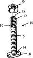
图1为依据本发明的第一优选实施方式构造的抽水马桶螺栓的透视图;Figure 1 is a perspective view of a toilet bolt constructed in accordance with a first preferred embodiment of the present invention;
图2为图1的抽水马桶螺栓的俯视图;Fig. 2 is a top view of the flush toilet bolt of Fig. 1;
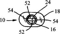
图3为依据本发明的第二优选实施方式构造的抽水马桶螺栓的透视图;Figure 3 is a perspective view of a toilet bolt constructed in accordance with a second preferred embodiment of the present invention;
图4为图3的抽水马桶螺栓的俯视图;Fig. 4 is a top view of the flush toilet bolt of Fig. 3;
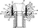
图5为马桶安装的横截面图,其展示了图1-4的抽水马桶螺栓;Figure 5 is a cross-sectional view of a toilet installation showing the toilet bowl bolts of Figures 1-4;
图6为用在马桶的安装中的带有图1-5的改进的抽水马桶螺栓的马桶法兰盘的俯视图。Figure 6 is a top view of the toilet flange with the improved toilet bolt of Figures 1-5 for use in a toilet installation.
优选实施方式详述Detailed Description of Preferred Embodiments
现在转到附图并首先转到图1-2,其示出了用在马桶安装中的抽水马桶螺栓10,该螺栓10包括上端12和下端14以及在上端12和下端14之间延伸的带螺纹的主体16。下端14终止于实质上阔椭圆形的底座18。上端12包括切刻部分。Turning now to the drawings and first to FIGS. 1-2, there is shown a
在第一优选实施方式中,切刻部分包含凹进的切刻部分22。该凹进的切刻部分22被构造成提供对阔椭圆形底座18的方向的可视的指示。例如,如所展示的那样,凹进的切刻部分22可以实质上平行于阔椭圆形底座18的长轴。可选择地,凹进的切刻部分22可以实质上垂直于阔椭圆形底座18的长轴。In the first preferred embodiment, the notches comprise recessed
切刻部分22的底部用作螺栓10的折断点。在马桶安装之后,该折断点应位于螺母的顶部上方而低于所安装的马桶的盖子的顶部。其优选地但非必须地与标准Johnny螺栓上的边缘切刻部分的位置保持一致。到达该位置的自顶向下的深度(以及因此螺栓的初始长度)没有在带有切刻部分的延伸部分被折断之后螺栓的最终长度重要。1/2”英寸的自顶向下的深度当前优选地为±1/4”英寸。对于三个标准螺栓长度,螺栓10的带螺纹的部分16的初始长度和最终长度被列明于下面的表1中:The bottom of the notched
表1:螺栓长度Table 1: Bolt Lengths
切刻部分22的侧翼表面(flanking surface)也提供“制动”表面,在使用另外的工具比如扳手将螺母紧固到螺栓上的同时,该“制动”表面允许螺丝刀或类似工具插入切刻部分22,以保持螺栓10使其不会从它的想要的方向转动出去。为了接收这样的工具,在0.010到0.150英寸之间的切刻部分宽度是优选的。在1/4”到5/16”直径的螺栓的情形中,对于折断点所需的深度对于接收这样的工具绰绰有余。The flanking surface of the notched
现在转到图3和图4,其示出了本发明的第二优选实施方式,其中切刻部分为凸出的切刻部分24。该凸出的切刻部分24具有相对宽的平坦侧面52,该侧面52被相对窄的弧形侧面54分开。类似于凹进的切刻部分22,其优选地中心定位于螺栓10的轴向中心线上。凸出的切刻部分24起到和上文描述的凹进的切刻部分22的所有作用一样的作用,这些作用包括方向指示、制动协助以及折断协助功能。因此其宽度(即,侧面54的长度)等于对应的凹进的切刻部分的宽度,对于直径为1/4”到5/16”的螺栓,优选地为0.010到0.150英寸宽。对于“标准”长度螺栓,其深度也优选地与上面的表1中所列明的相同。Turning now to FIGS. 3 and 4 , a second preferred embodiment of the invention is shown wherein the notches are
螺栓10的上端是带螺纹的,以便允许螺母被拧紧到螺栓的最上端上。在凹进的切刻部分22的情形中,切刻部分端部的全部的剩余边缘优选地为带螺纹的,如图1中最佳地示出。在凸出的切刻部分24的情形中,对置的相对窄的侧面54为带螺纹的,如图3中最佳地示出。The upper end of the
对于凹进的切刻部分22或凸出的切刻部分24,可以通过并入边缘槽50来协助将螺栓10在折断点折断,在折断点处其类似于或甚至相同于Johnny螺栓中所见的槽。此种槽应为大约3/16”深。For either the
现在转到图5和图6,其示出了使用本发明的抽水马桶螺栓10的马桶组件。示出了具有用于插入抽水马桶螺栓10的狭槽28和28’的马桶法兰盘26。示出了马桶30,其中马桶30的基座32具有两个竖直孔34,马桶螺栓10穿过该竖直孔插入。一般地由蜡形成的密封环40被压在马桶法兰盘26和基座32之间。Turning now to Figures 5 and 6, there is shown a toilet assembly using the
仍然参照图5和图6,其展示了马桶法兰盘26安置在将要安装马桶的地面上,同时本发明的马桶螺栓10被插入到法兰盘26中的两组狭槽28和28’中的一组。狭槽28为弧形的,带有加大的端部。狭槽28’为从法兰盘26的外边缘向内径向地延伸的槽口。螺栓10可以通过在底座18的长轴平行于狭槽28延伸的条件下,插入到狭槽28的加大的端部中,然后将螺栓10移动到较窄的区域,并将螺栓转动90°以便底座的长轴垂直于狭槽,由此被插入到弧形的狭槽28中。螺栓10可以通过简单地将其从外侧滑进狭槽28’而被插入到径向狭槽或槽口28’中,并且如果有必要,可以转动螺栓10以便底座18的长轴垂直于狭槽28’。Still referring to Figures 5 and 6, it is shown that the
仍然参照图5和图6,一般地由蜡形成的密封环40随后被放置在法兰盘26和螺栓10上,以便螺栓10延伸穿过密封环。马桶30的基座,即基座32随后通过将抽水马桶螺栓10的上端12插入穿过马桶的基座32中的孔34而被安装在蜡环上。马桶螺栓10的切刻部分22或24对用户指示抽水马桶螺栓10的阔椭圆形底座18的长轴的方向,以便用户确信螺栓在安装过程中不会滑动出所需位置。Still referring to FIGS. 5 and 6 , a
一旦马桶30被降低到地面上并就位,螺母36和垫圈(未示出)或类似的紧固件装置被从上方拧紧到抽水马桶螺栓10上。因为螺纹一路延伸到螺栓的端部,所以,即使是不寻常的厚的蜡环或其它条件最初地只留下螺栓10的最末端露出,该螺母可也以被即使到螺纹上。螺母向下通过螺纹主体16被紧固在马桶螺栓10上。螺母36被向下抵靠着马桶30的基座32紧固,以便抽水马桶螺栓10被牢固地保持顶靠着法兰盘的底部并且马桶30被顶靠着地面固定。用户可以通过使用合适的工具与切刻部分22或24的制动表面啮合来防止螺栓10在稍后阶段的盲紧固(nighttightening)的过程中转动。在凹进的切刻部分22的情形中,此啮合是使用螺丝刀或类似工具实现的,而在凸出的切刻部分24的情形中此啮合是使用扳手或钳子实现的。在任何一种情形中,制动表面都实质上足够坚固以经受安装过程中的制动所需的扭矩,但是也足够不坚固以便多余部分可以容易地被移除,如下文将另外讨论的那样。如有必要,用户可以将切刻部分的方向用作向导,以转动螺栓以确保在最终紧固之前的最佳的方向。一旦抽水马桶螺栓10被固定在基座32内,一般地由塑料或陶瓷制成的螺帽(未示出)被拧紧或以其它形式安装在螺栓10的露出部分上。Once the
螺栓10的多余部分对于标准尺寸的螺帽一般太长而使得标准尺寸的螺帽不能配合在其上。因此,螺栓10的多余部分必须被移除以便螺帽可以牢固地配合在螺栓上,并且进而顶靠着马桶30的基座32。螺栓10的切刻部分20提供折断点以便容易移除螺栓的多余部分。该折断点被与切刻部分20以及切刻部分20的夹持表面完全地整合在一起,以便帮助安装者安装马桶30。在凹进的切刻部分22的情形中,在将工具的头部,比如螺丝刀的头部插入到凹进的切刻部分22中时,该多余部分可以容易地被移除一端。安装者随后简单地向着凹进的切刻部分22的一侧拉该工具的头部以便实质上削弱相邻于凹进的切刻部分端部的材料。然后,安装者在相反方向移动工具以弯曲相邻于切刻部分的另一侧的材料。一旦相邻于凹进的切刻部分22的端部的相对侧的部分的一侧充分地弯曲,它们可以使用钳子或类似工具被容易地移除。为了帮助此过程,如有必要,凹进的切刻部分22可以被定位成垂直于螺栓10的阔椭圆形底座18的长轴,以便当移除螺栓10的多余部分时,细长的底座对螺栓倾斜提供增加的阻力,从而减少螺栓会倾斜并剥落马桶30的瓷料的风险。The excess portion of the
在凸出的切刻部分24的情形中,钳子或类似工具可以被用于移除螺栓10的多余部分。与凹进的切刻部分22类似,凸出的切刻部分24可以垂直于阔椭圆形底座18的长轴延伸,以便在移除螺栓10的多余部分的过程中,马桶30的瓷料不像如果切刻部分平行于阔椭圆形底座18的长轴延伸时那样容易被剥落。In the case of the protruding
在螺栓10的多余的端部部分在折断点被折断之后,标准螺帽(未示出)可以被以任何想要的形式安装在螺栓的上。After the excess end portion of the
可以对本发明做出很多改动和修改而不背离本发明的精神。这些改动中的一些改动的范围可以通过比较如上文描述的各种实施方式而被理解。其余的改变的范围将通过权利要求变得明显。Many changes and modifications can be made to the present invention without departing from the spirit of the invention. The scope of some of these modifications can be appreciated by comparing various embodiments as described above. The rest of the range of changes will become apparent from the claims.
Claims (19)

Applications Claiming Priority (3)
| Application Number | Priority Date | Filing Date | Title |
|---|---|---|---|
| US11/670,211US7954179B2 (en) | 2007-02-01 | 2007-02-01 | Water closet bolt |
| US11/670,211 | 2007-02-01 | ||
| PCT/US2008/051645WO2008094784A1 (en) | 2007-02-01 | 2008-01-22 | Water closet bolt |
Publications (2)
| Publication Number | Publication Date |
|---|---|
| CN101646828A CN101646828A (en) | 2010-02-10 |
| CN101646828Btrue CN101646828B (en) | 2013-01-30 |
Family
ID=39357921
Family Applications (1)
| Application Number | Title | Priority Date | Filing Date |
|---|---|---|---|
| CN2008800100322AActiveCN101646828B (en) | 2007-02-01 | 2008-01-22 | toilet bowl bolt |
Country Status (5)
| Country | Link |
|---|---|
| US (2) | US7954179B2 (en) |
| CN (1) | CN101646828B (en) |
| CA (1) | CA2677222C (en) |
| GB (1) | GB2459397B (en) |
| WO (1) | WO2008094784A1 (en) |
Families Citing this family (13)
| Publication number | Priority date | Publication date | Assignee | Title |
|---|---|---|---|---|
| DE102012023717A1 (en)* | 2012-12-05 | 2014-06-05 | Eads Deutschland Gmbh | Indication bolts for monitoring adhesive joints in structural components |
| USD699555S1 (en)* | 2013-04-30 | 2014-02-18 | Frederick Yazich | Indexed bolt |
| USD766069S1 (en)* | 2014-01-03 | 2016-09-13 | Jody D. Miller | Fastener set for a toilet flange |
| US9425599B2 (en)* | 2014-01-22 | 2016-08-23 | Hutchinson Wire Solutions, LLC | Devices, systems, and methods to secure wires and prevent wire theft |
| US9204595B2 (en)* | 2014-01-29 | 2015-12-08 | Textron Inc. | Quick connect system for attaching motors to cylinder mowers |
| US20150368891A1 (en)* | 2014-04-01 | 2015-12-24 | Jody D. Miller | Toilet Fastening System |
| US10060115B2 (en)* | 2014-04-01 | 2018-08-28 | Aiim, Llc | Toilet fastening system |
| CN105756163A (en)* | 2016-04-14 | 2016-07-13 | 俞祖林 | Structure-improved toilet |
| TWI624602B (en)* | 2017-08-04 | 2018-05-21 | 吳易璋 | Pressing type screw |
| US10876566B2 (en)* | 2019-02-28 | 2020-12-29 | James Michael McLaughlin | Method and apparatus for maintaining a relationship between separate objects |
| USD996962S1 (en)* | 2020-11-17 | 2023-08-29 | National Nail Corp. | Screw |
| USD978658S1 (en)* | 2021-06-10 | 2023-02-21 | Kent Warner | Toilet flange repair kit |
| USD973477S1 (en)* | 2021-07-01 | 2022-12-27 | Frank Wu | Engine mount adjustment bolt |
Citations (4)
| Publication number | Priority date | Publication date | Assignee | Title |
|---|---|---|---|---|
| US3339215A (en)* | 1965-01-03 | 1967-09-05 | Thomas D Flood | Self-retaining closet bolt |
| US4907923A (en)* | 1988-08-25 | 1990-03-13 | Mcgrath Jr Terence J | Closet bolt |
| US6125479A (en)* | 1998-11-30 | 2000-10-03 | Fraleigh; William T. | Floor mounting system for toilet stools |
| US6430756B1 (en)* | 1998-12-28 | 2002-08-13 | George W. Reilly | Closet bolt |
Family Cites Families (28)
| Publication number | Priority date | Publication date | Assignee | Title |
|---|---|---|---|---|
| US927611A (en)* | 1909-07-13 | Henry J Bassler | Connection for water-closets. | |
| US3125765A (en)* | 1964-03-24 | Toilet bowl attachment means | ||
| US952602A (en)* | 1909-04-20 | 1910-03-22 | Joseph S Candee | Closet-joint. |
| US1055330A (en)* | 1911-06-23 | 1913-03-11 | Peter M Kling | Bolt. |
| US1093434A (en)* | 1913-03-13 | 1914-04-14 | Samuel R Kent | Steam-boiler plug. |
| US1507488A (en)* | 1922-05-09 | 1924-09-02 | Kraemer Emil Edward | Extension bolt |
| US1813790A (en)* | 1927-07-02 | 1931-07-07 | Wildish Henry William | Furnace lining |
| US3346286A (en)* | 1965-08-31 | 1967-10-10 | Burroughs Corp | Component mounting employing a threaded bolt driven at its threaded end |
| US3329057A (en)* | 1966-06-20 | 1967-07-04 | Robert B Salz | Threaded fastener device |
| US3725079A (en) | 1967-05-26 | 1973-04-03 | Gaf Corp | Coating formulations containing phosphate esters of glycidol polyethers |
| US3601823A (en)* | 1970-05-22 | 1971-08-31 | Harold Isaacs | Unitary plastic cap, nut and washer combination |
| US3669171A (en)* | 1970-06-08 | 1972-06-13 | Morris Yavitch | Fastener assembly |
| JPS506816B1 (en)* | 1970-12-31 | 1975-03-18 | ||
| US3775780A (en)* | 1972-07-17 | 1973-12-04 | Multi Fittings Ltd | Water closet coupling |
| US3846851A (en)* | 1972-10-10 | 1974-11-12 | Genova Products | Plumbing fitting |
| US3896510A (en)* | 1973-09-10 | 1975-07-29 | Connell Joseph F O | Apparatus for installing a water closet bowl |
| US4212486A (en)* | 1978-05-19 | 1980-07-15 | The Logsdon Foundation | Water closet protector stabilizer |
| US4233697A (en)* | 1978-12-26 | 1980-11-18 | Cornwall Kenneth R | Protective flange cover and method of use |
| US4574402A (en)* | 1982-05-21 | 1986-03-11 | Brown Sr Theodore C | Two piece closet ring with moisture membrane clamping arrangement |
| US4530629A (en)* | 1982-09-27 | 1985-07-23 | Lawrence Sakow | Toilet bowl mounting bolt assembly |
| US4492500A (en)* | 1983-02-10 | 1985-01-08 | Ewing Peter D | Torque limiting set screw |
| JPH0339605Y2 (en)* | 1986-07-23 | 1991-08-21 | ||
| US4780915A (en)* | 1987-11-27 | 1988-11-01 | Casper Cuschera | Toilet floor flange |
| US4827539A (en)* | 1988-01-04 | 1989-05-09 | Kiziah Floyd G | Adjustable closet floor flange |
| US6270304B1 (en)* | 1993-03-23 | 2001-08-07 | Yosef Freedland | Tension adjusting device |
| US6698986B2 (en)* | 1998-08-31 | 2004-03-02 | William T. Fraleigh | Method and means for mounting a toilet stool |
| FR2829092B1 (en)* | 2001-09-04 | 2007-01-05 | Meritor Light Vehicle Sys Ltd | CABRIOLET DOOR WITH ADJUSTABLE RAIL AND CORRESPONDING ASSEMBLY METHOD |
| US6896510B2 (en)* | 2002-05-08 | 2005-05-24 | Susumu Matsuyama | Apparatus and methods for controlling a flame |
- 2007
- 2007-02-01USUS11/670,211patent/US7954179B2/enactiveActive
- 2008
- 2008-01-22WOPCT/US2008/051645patent/WO2008094784A1/enactiveApplication Filing
- 2008-01-22CACA2677222Apatent/CA2677222C/enactiveActive
- 2008-01-22GBGB0913267Apatent/GB2459397B/enactiveActive
- 2008-01-22CNCN2008800100322Apatent/CN101646828B/enactiveActive
- 2011
- 2011-05-03USUS13/099,619patent/US9416525B2/enactiveActive
Patent Citations (4)
| Publication number | Priority date | Publication date | Assignee | Title |
|---|---|---|---|---|
| US3339215A (en)* | 1965-01-03 | 1967-09-05 | Thomas D Flood | Self-retaining closet bolt |
| US4907923A (en)* | 1988-08-25 | 1990-03-13 | Mcgrath Jr Terence J | Closet bolt |
| US6125479A (en)* | 1998-11-30 | 2000-10-03 | Fraleigh; William T. | Floor mounting system for toilet stools |
| US6430756B1 (en)* | 1998-12-28 | 2002-08-13 | George W. Reilly | Closet bolt |
Also Published As
| Publication number | Publication date |
|---|---|
| GB2459397B (en) | 2011-04-06 |
| CA2677222A1 (en) | 2008-08-07 |
| GB2459397A (en) | 2009-10-28 |
| US20110214227A1 (en) | 2011-09-08 |
| US7954179B2 (en) | 2011-06-07 |
| US20080184469A1 (en) | 2008-08-07 |
| US9416525B2 (en) | 2016-08-16 |
| WO2008094784A1 (en) | 2008-08-07 |
| CN101646828A (en) | 2010-02-10 |
| GB0913267D0 (en) | 2009-09-02 |
| CA2677222C (en) | 2015-10-06 |
Similar Documents
| Publication | Publication Date | Title |
|---|---|---|
| CN101646828B (en) | toilet bowl bolt | |
| US7959439B2 (en) | Apparatus, system, and method for implanting dental prosthesis | |
| US6430756B1 (en) | Closet bolt | |
| US6282999B1 (en) | Plumbing part installation and removal tool | |
| US6698986B2 (en) | Method and means for mounting a toilet stool | |
| US10465370B2 (en) | Pipe connector | |
| US6443495B1 (en) | Multiple level floor flange apparatus and associated method | |
| US7055184B2 (en) | Closet flange with knockout retainer | |
| US20090119826A1 (en) | Flexible flange apparatus with a flexible membrane | |
| TW202012754A (en) | Systems and methods for a cast-in anchor for a metal deck | |
| US9341364B2 (en) | Toilet installation tool | |
| US20080178455A1 (en) | Method and apparatus for installing a waste disposer sink mount | |
| US4907301A (en) | Method for setting toilet bowls | |
| WO2014016703A2 (en) | Flexible toilet seal and method | |
| CA2491336C (en) | Apparatus and method for installation of recessed lighting fixture | |
| US7409893B2 (en) | Tool for holding a bolt | |
| KR102133937B1 (en) | Duct hanger | |
| US20040020336A1 (en) | Tool for quick removal and installation of drain | |
| GB2624392A (en) | Cistern connector | |
| JP5298843B2 (en) | Marking jig for piping | |
| US20060249603A1 (en) | Adjustable drop sprinkler and installation tool | |
| US20060143813A1 (en) | Apparatus and method for placement of a water closet fitting | |
| US20040160057A1 (en) | Base tee connection | |
| US20140300097A1 (en) | Conduit stub-up connector assembly and method | |
| US9938708B1 (en) | Apparatus for securing a toilet to a floor |
Legal Events
| Date | Code | Title | Description |
|---|---|---|---|
| C06 | Publication | ||
| PB01 | Publication | ||
| C10 | Entry into substantive examination | ||
| SE01 | Entry into force of request for substantive examination | ||
| C14 | Grant of patent or utility model | ||
| GR01 | Patent grant |