CN101643116A - Tiltrotor controlled by double-propeller vertical duct - Google Patents
Tiltrotor controlled by double-propeller vertical ductDownload PDFInfo
- Publication number
- CN101643116A CN101643116ACN200910090230ACN200910090230ACN101643116ACN 101643116 ACN101643116 ACN 101643116ACN 200910090230 ACN200910090230 ACN 200910090230ACN 200910090230 ACN200910090230 ACN 200910090230ACN 101643116 ACN101643116 ACN 101643116A
- Authority
- CN
- China
- Prior art keywords
- propeller
- duct
- vertical
- end cover
- aircraft
- Prior art date
- Legal status (The legal status is an assumption and is not a legal conclusion. Google has not performed a legal analysis and makes no representation as to the accuracy of the status listed.)
- Granted
Links
Images


Landscapes
- Transmission Devices (AREA)
Abstract
Description
Translated fromChinese(一)技术领域(1) Technical field
本发明涉及一种倾转旋翼飞机,尤其涉及一种使用双螺旋桨垂直涵道控制的倾转旋翼飞机,属于航空飞行器设计技术领域。The invention relates to a tilt-rotor aircraft, in particular to a tilt-rotor aircraft controlled by a double-propeller vertical duct, and belongs to the technical field of aviation vehicle design.
(二)背景技术(2) Background technology
倾转旋翼飞行器兼有直升机和固定翼飞机的特点。与固定翼飞机相比,该种飞行器能够垂直起降,没有对机场跑道的依赖,能够实现悬停和小速度前飞;与传统直升机相比,倾转旋翼机有更大的巡航速度和航程,巡航过程中由机翼产生升力,比直升机更经济,因而该种飞行器自诞生以来就受到广泛关注。对于倾转旋翼机研究最早和最系统的国家是美国,经过几十年的研究、论证和试验,美国研制出了该类飞行器的代表机型V22并投入了实用。关于倾转旋翼机的发展历程参见文献Malcolm Foster,The Future Evolution of the Tiltrotor,AIAA 2003-2652,2003.所述(Malcolm Foster,倾转旋翼机将来的发展,AIAA 2003-2652,2003)A tiltrotor aircraft combines features of a helicopter and a fixed-wing aircraft. Compared with fixed-wing aircraft, this type of aircraft can take off and land vertically, without relying on the airport runway, and can achieve hovering and low-speed forward flight; compared with traditional helicopters, tilt-rotor aircraft have greater cruising speed and range , the lift generated by the wings in the cruising process is more economical than the helicopter, so this kind of aircraft has been widely concerned since its birth. The earliest and most systematic research on tilt rotor aircraft is the United States. After decades of research, demonstration and testing, the United States has developed the V22, a representative model of this type of aircraft, and put it into practical use. For the development process of the tilt rotor, see the document Malcolm Foster, The Future Evolution of the Tiltrotor, AIAA 2003-2652, 2003. (Malcolm Foster, the future development of the tilt rotor, AIAA 2003-2652, 2003)
V22采用横列式双旋翼常规布局,在垂直飞行及垂直飞行状态和平飞状态之间的过渡过程(以下简称转换飞行模式)下,由于舵面气动效率不足,主要靠旋翼周期变距来实现飞机的姿态控制,在正常平飞模式下,由于飞机有了较大的前飞速度,各个舵面的气动效率足够,主要采用飞机的舵面来控制飞机的姿态。各种飞行模式的控制方式如下:The V22 adopts the conventional layout of horizontal twin-rotors. In the transition process between vertical flight and vertical flight state and level flight state (hereinafter referred to as the switching flight mode), due to the insufficient aerodynamic efficiency of the rudder surface, the aircraft's control is mainly achieved by changing the rotor pitch. Attitude control, in the normal level flight mode, because the aircraft has a greater forward flight speed, the aerodynamic efficiency of each rudder surface is sufficient, and the rudder surface of the aircraft is mainly used to control the attitude of the aircraft. The control methods of various flight modes are as follows:
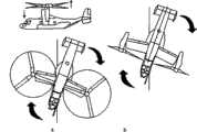
(1)在垂直飞行和转换飞行模式下,依靠两副旋翼的周期变距来控制飞机的纵向姿态,如图1a所示;在平飞状态下采用升降舵控制纵向姿态,如图1b所示;在图1a中,周期变距使得桨盘前倾,形成纵向控制力矩,飞机在控制纵向姿态的同时,会形成向前的分力,引起飞机向前飞行,产生耦合效应;在图1b中,升降舵偏转,作用在平尾及升降舵上的力改变,形成纵向控制力矩。(1) In the vertical flight and transition flight modes, the longitudinal attitude of the aircraft is controlled by the periodic pitch change of the two rotors, as shown in Figure 1a; in the level flight state, the elevator is used to control the longitudinal attitude, as shown in Figure 1b; In Figure 1a, the cyclical pitch makes the paddle disc tilt forward, forming a longitudinal control moment, while the aircraft controls the longitudinal attitude, it will form a forward component force, causing the aircraft to fly forward and produce a coupling effect; in Figure 1b, When the elevator deflects, the force acting on the horizontal tail and the elevator changes, forming a longitudinal control moment.
(2)在垂直飞行和转换飞行模式下,依靠两副旋翼的周期变距的差动来控制飞机的航向姿态,如图2a所示;在平飞状态下采用方向舵控制航向姿态,如图2b所示;图2a中,一个旋翼的纵向周期变距向前,一个旋翼向后,形成了旋翼拉力的前后交叉,产生力航向力矩,实现飞机的航向操作。在图2b中,方向舵偏转,作用在垂尾和方向舵上的气动力发生变化,形成了航向控制力矩。(2) In the vertical flight and switching flight modes, the directional attitude of the aircraft is controlled by the difference between the two rotors’ periodic pitch change, as shown in Figure 2a; in the level flight state, the rudder is used to control the directional attitude, as shown in Figure 2b As shown in Figure 2a, the longitudinal period of one rotor is variable pitch forward, and the other rotor is backward, forming the front and rear crossing of rotor tension, generating force and heading moment, and realizing the heading operation of the aircraft. In Figure 2b, the rudder deflects, and the aerodynamic force acting on the vertical tail and rudder changes, forming a heading control moment.
(3)在垂直飞行和转换飞行模式下,依靠两副旋翼的总距差动来控制飞机的滚转姿态,如图3a所示;在平飞状态下采用副翼控制控制滚转姿态,如图3b所示;图3a中,左右两副旋翼的总距差动变化,一副旋翼拉力增加,一副旋翼拉力减少,就形成了滚转控制力矩。在图3b中,副翼差动偏转,作用在飞机左右两侧机翼上的气动力发生改变,一边增大一边减小,形成滚转控制力矩。(3) In the vertical flight and switching flight modes, the roll attitude of the aircraft is controlled by the collective pitch differential of the two rotors, as shown in Figure 3a; in the level flight state, the aileron control is used to control the roll attitude, as shown in As shown in Figure 3b; in Figure 3a, the differential change of the collective pitch of the left and right rotors, the tension of one rotor increases, and the tension of the other rotor decreases, forming a roll control moment. In Figure 3b, the ailerons are differentially deflected, and the aerodynamic force acting on the left and right wings of the aircraft changes, increasing while decreasing, forming a roll control moment.
关于上文中提到的周期变距机构的结构及工作原理,参见文献张呈林 张小谷 等编著,直升机部件设计,南京航空学院印刷厂1986.文中所述。For the structure and working principle of the period variable pitch mechanism mentioned above, please refer to the document edited by Zhang Chenglin, Zhang Xiaogu, etc., Design of Helicopter Components, Printing Factory of Nanjing Aeronautical Institute, 1986. Described in the article.
关于周期变距控制模式的倾转旋翼机控制原理的详细资料,可以参见文献杨军 吴希明 等编著 倾转旋翼机飞行控制,航空工业出版社,2006.文中所述。For detailed information on the control principle of the tiltrotor aircraft in the period variable pitch control mode, you can refer to the document Yang Jun, Wu Ximing, et al., Edited by Tilter Rotor Flight Control, Aviation Industry Press, 2006. Described in the article.
通过上面以V22为代表的靠周期变距来控制垂直飞行和转换飞行模式的倾转旋翼机的控制方式可以看出,在飞机控制舵面效率不足的情况下,所有的姿态控制都是靠周期变距来控制,控制方式复杂。在使用周期变距控制纵向姿态的时候,会引起飞机向前飞行的耦合效应。而且周期变距机构结构复杂,复杂的结构和控制方式对于倾转旋翼机的安全性和可靠性都是不利的。同时,周期变距方式控制飞机姿态,由于控制力力臂短,产生控制力矩的效率不高。It can be seen from the control method of the tiltrotor aircraft represented by V22 that controls the vertical flight and switches the flight mode by periodic pitch change, that all attitude control is by periodic control when the efficiency of the aircraft control rudder surface is insufficient. Variable distance to control, the control method is complicated. When using cyclic pitch control to control the longitudinal attitude, it will cause the coupling effect of the aircraft flying forward. Moreover, the structure of the periodic variable pitch mechanism is complex, and the complex structure and control methods are unfavorable to the safety and reliability of the tilt rotor aircraft. At the same time, the periodic variable pitch method controls the attitude of the aircraft, because the control force arm is short, the efficiency of generating control torque is not high.
(三)发明内容(3) Contents of the invention
1、目的1. Purpose
本发明的目的是为了提供一种使用双螺旋桨垂直涵道控制的倾转旋翼飞机,该飞机克服了现有技术的不足,解决了上述周期变距控制方式的倾转旋翼机中存在的问题。The purpose of the present invention is in order to provide a kind of tilting rotor aircraft that uses twin propellers vertical duct control, this aircraft has overcome the deficiency of prior art, has solved the problem that exists in the tilting rotor aircraft of above-mentioned periodic variable pitch control mode.
2、技术方案2. Technical solution
本发明一种使用双螺旋桨垂直涵道控制的倾转旋翼飞机,该飞机采用并列双旋翼、常规气动布局的设计,它是由机身、平直机翼、旋翼、短舱、副翼、垂直尾翼、方向舵、升降舵、水平尾翼、起落架、动力及减速系统及双螺旋桨垂直涵道结构组成。平直机翼安装在机身的中段两侧,旋翼安装在短舱的端部,起落架的主体位于机身腹部,机身两侧的平直机翼支撑着端部的短舱,副翼连接在平直机翼外侧,水平尾翼与机身尾部相连,升降舵连接在水平尾翼后面,两个垂直尾翼连接在水平尾翼两侧,方向舵连接在垂直尾翼后面,双螺旋桨垂直涵道结构位于水平尾翼中间,动力及减速系统位于机身中部。The present invention is a tilt rotor aircraft controlled by double propeller vertical duct, the aircraft adopts the design of parallel double rotors and conventional aerodynamic layout, and it is composed of fuselage, straight wing, rotor, nacelle, aileron, vertical Tail, rudder, elevator, horizontal tail, landing gear, power and deceleration system and double propeller vertical duct structure. The straight wings are installed on both sides of the middle section of the fuselage, the rotor is installed at the end of the nacelle, the main body of the landing gear is located at the belly of the fuselage, the straight wings on both sides of the fuselage support the nacelle at the end, and the ailerons Connected to the outside of the straight wing, the horizontal stabilizer is connected to the rear of the fuselage, the elevator is connected to the rear of the horizontal stabilizer, the two vertical stabilizers are connected to both sides of the horizontal stabilizer, the rudder is connected to the rear of the vertical stabilizer, and the double propeller vertical duct structure is located on the horizontal stabilizer In the middle, the power and deceleration system is located in the middle of the fuselage.
该机身主要用于安装各部件和容纳载荷,采用传统的半硬壳式结构;The fuselage is mainly used to install various components and accommodate loads, and adopts a traditional semi-monocoque structure;
该平直机翼为矩形平直机翼,采用传统的悬臂式双梁式结构,由翼肋+桁条+蒙皮组成抗扭结构;The straight wing is a rectangular straight wing, adopting the traditional cantilever double-beam structure, and the torsion-resistant structure is composed of ribs + stringers + skin;
该旋翼的桨叶平面形状为矩形,旋翼桨叶数目为两片(重载机型可以增加桨叶片数);旋翼没有周期变距机构,它设有旋翼总距操纵机构,通过旋翼总距操纵机构来改变旋翼的总距,从而改变旋翼拉力大小;The planar shape of the rotor blades is rectangular, and the number of rotor blades is two (heavy-load models can increase the number of blades); Mechanism to change the collective pitch of the rotor, thereby changing the magnitude of the rotor pull;
该短舱包含短舱倾转机构、减速箱、减速锥齿轮、旋翼总距操纵机构、旋翼转轴;放置在机身中部的动力及减速系统通过传动轴输出动力到短舱驱动减速锥齿轮,经过减速带动旋翼转轴及旋翼旋转,短舱通过短舱倾转机构与机翼连接,短舱倾转机构使得短舱可与机翼发生相对转动;The nacelle includes a nacelle tilting mechanism, a reduction box, a reduction bevel gear, a rotor collective control mechanism, and a rotor shaft; the power and reduction system placed in the middle of the fuselage outputs power to the nacelle to drive the reduction bevel gear through the transmission shaft. The deceleration drives the rotor shaft and the rotor to rotate, the nacelle is connected to the wing through the nacelle tilting mechanism, and the nacelle tilting mechanism allows the nacelle to rotate relative to the wing;
该副翼平面形状为矩形,采用蒙皮加骨架的结构,骨架由单梁+翼肋+桁条组成;The plane shape of the aileron is rectangular, and it adopts the structure of skin and skeleton, and the skeleton is composed of single beam + wing rib + stringer;
该垂直尾翼平面形状为矩形,采用蒙皮加骨架结构,骨架由双梁+翼肋+桁条组成;The plane shape of the vertical tail is rectangular, and it adopts a skin plus skeleton structure, and the skeleton is composed of double beams + wing ribs + stringers;
该方向舵的平面形状为矩形,采用蒙皮加骨架的结构,骨架由单梁+翼肋+桁条+组成;The plane shape of the rudder is rectangular, and it adopts the structure of skin and skeleton, and the skeleton is composed of single beam + wing rib + stringer +;
该升降舵平面形状为矩形,采用蒙皮加骨架的结构,骨架由单梁+翼肋+桁条组成;The plane shape of the elevator is rectangular, and it adopts the structure of skin and skeleton, and the skeleton is composed of single beam + wing rib + stringer;
该水平尾翼平面形状为矩形,采用蒙皮加骨架结构,骨架由双梁+翼肋+桁条组成;The plane shape of the horizontal stabilizer is rectangular, and it adopts a skin plus skeleton structure, and the skeleton is composed of double beams + wing ribs + stringers;
该起落架采用传统的前三点式起落架;The landing gear adopts the traditional tricycle landing gear;
该动力及减速系统采用1-2台传统的涡轮轴或活塞式发动机,安装在机身内部或平直机翼根部,燃油及减速系统布置在机身中部和平直机翼内;The power and deceleration system adopts 1-2 traditional turboshaft or piston engines, which are installed inside the fuselage or at the root of the straight wing, and the fuel and deceleration system are arranged in the middle of the fuselage and inside the straight wing;
该双螺旋桨垂直涵道结构是本专利申请所采用的新颖的技术特征,依靠它来控制倾转旋翼飞机,实现垂直飞行和飞行模式的转换:The dual propeller vertical duct structure is a novel technical feature adopted in this patent application, relying on it to control the tilt rotor aircraft and realize the conversion of vertical flight and flight mode:
所述双螺旋桨垂直涵道结构,它是由垂直涵道、螺旋桨变速及总距操纵装置、螺旋桨变速箱支撑结构、涵道端盖、涵道端盖驱动装置、涵道端盖运动滑轨组成。垂直涵道布置在水平尾翼中部,螺旋桨变速及总距操纵装置在垂直涵道中部并位于上、下螺旋桨之间,并由螺旋桨变速箱支撑结构来支撑,涵道端盖安装在水平尾翼的右部上下表面内侧,涵道端盖驱动装置和涵道端盖运动滑轨安装在水平尾翼的右部中间。The double propeller vertical duct structure is composed of a vertical duct, a propeller speed change and collective control device, a propeller gearbox support structure, a duct end cover, a duct end cover driving device, and a duct end cover moving slide rail. The vertical duct is arranged in the middle of the horizontal stabilizer, and the propeller speed change and collective pitch control device is located in the middle of the vertical duct between the upper and lower propellers, and is supported by the supporting structure of the propeller gearbox. The end cover of the duct is installed on the right of the horizontal stabilizer On the inner side of the upper and lower surfaces, the duct end cover driving device and the duct end cover moving slide rail are installed in the middle of the right part of the horizontal stabilizer.
该垂直涵道包含上、下两副螺旋桨,百叶窗式滑流片,滑流片控制装置和涵道螺旋桨动力输入轴;该上、下螺旋桨各由两片带扭转的矩形桨叶构成,它布置在垂直涵道的上部和下部,与螺旋桨驱动轴相连,上、下螺旋桨转向相反,产生的旋转扭矩相互抵消;上、下螺旋桨设有螺旋桨总距操纵机构,可以同步改变总距大小,从而改变螺旋桨的拉力,控制飞机的纵向姿态;该百叶窗式滑流片由多个叶片组成,各个叶片的平面形状为矩形,叶片通过与机身轴线平行的转轴支撑在垂直涵道的中部,各个叶片同步偏转,偏转角由滑流片控制装置进行控制,滑流片控制装置主要由伺服电机+齿条构成,伺服电机带动齿条平动,齿条再带动叶片转轴转动;螺旋桨旋转产生的滑流流过百叶窗式滑流片产生侧向力,实现对飞机的航向控制。The vertical duct includes two pairs of upper and lower propellers, louver-type slip vane, slip vane control device and ducted propeller power input shaft; the upper and lower propellers are each composed of two rectangular blades with twist, which are arranged The upper and lower parts of the vertical duct are connected to the drive shaft of the propeller. The upper and lower propellers turn in opposite directions, and the rotational torque generated cancels each other out. The pulling force of the propeller controls the longitudinal attitude of the aircraft; the louver-type slipstream blade is composed of multiple blades, each blade has a rectangular plane shape, and the blades are supported in the middle of the vertical duct by a rotating shaft parallel to the axis of the fuselage, and each blade is synchronized The deflection and the deflection angle are controlled by the slip vane control device. The slip vane control device is mainly composed of a servo motor + a rack. The servo motor drives the rack to move in translation, and the rack drives the blade shaft to rotate; the slip stream generated by the rotation of the propeller The louver-type slipstream generates lateral force to realize the heading control of the aircraft.
该螺旋桨变速及总距操纵装置位于垂直涵道中间,由螺旋桨变速箱支撑结构来支撑;它包含螺旋桨总距操纵机构、涵道变速锥齿轮、滚动轴承、螺旋桨驱动轴;动力及减速系统通过涵道螺旋桨动力输入轴输出动力到螺旋桨变速及总距操纵装置,通过涵道变速锥齿轮驱动螺旋桨驱动轴,带动安装在螺旋桨驱动轴上的下螺旋桨和上螺旋桨同时反向旋转,螺旋桨驱动轴由滚动轴承支撑,螺旋桨总距操纵机构操纵上、下螺旋桨的总距来改变上、下螺旋桨产生的控制力大小。该螺旋桨总距操纵机构是由舵机+摇臂+推拉杆组成,摇臂安装在舵机转轴上,推拉杆一端与摇臂相连,另一端与螺旋桨桨叶相连;该涵道变速锥齿轮是由三个圆锥齿轮组成,该三个圆锥齿轮由轴承支撑;The propeller speed change and collective pitch control device is located in the middle of the vertical duct and is supported by the support structure of the propeller gearbox; it includes the propeller collective pitch control mechanism, duct speed change bevel gears, rolling bearings, and propeller drive shafts; the power and reduction system passes through the duct The propeller power input shaft outputs power to the propeller speed change and collective pitch control device, drives the propeller drive shaft through the ducted speed change bevel gear, drives the lower propeller and the upper propeller installed on the propeller drive shaft to rotate in reverse at the same time, and the propeller drive shaft is supported by rolling bearings , the propeller collective pitch control mechanism manipulates the collective pitch of the upper and lower propellers to change the control force generated by the upper and lower propellers. The propeller collective control mechanism is composed of steering gear + rocker arm + push-pull rod, the rocker arm is installed on the steering gear shaft, one end of the push-pull rod is connected with the rocker arm, and the other end is connected with the propeller blade; the ducted variable speed bevel gear is Consists of three bevel gears supported by bearings;
该涵道端盖有上下两个,呈圆形状,上、下螺旋桨工作的时候,涵道端盖驱动装置把涵道端盖收入水平尾翼内部,垂直涵道处于开放状态;上、下螺旋桨停止工作时,涵道端盖驱动装置把涵道端盖从水平尾翼内推出,封闭垂直涵道,使水平尾翼光滑完整,减小飞行阻力。There are two upper and lower duct end covers, which are round in shape. When the upper and lower propellers are working, the duct end cover driving device puts the duct end cover into the inside of the horizontal empennage, and the vertical duct is in an open state; when the upper and lower propellers stop working, The duct end cover driving device pushes the duct end cover out of the horizontal stabilizer to close the vertical duct, making the horizontal stabilizer smooth and complete, and reducing flight resistance.
该涵道端盖驱动装置由伺服电机和齿轮齿条构成,伺服电机带动齿轮旋转,齿轮带动齿条平动,从而推动涵道端盖运动。The duct end cover driving device is composed of a servo motor and a rack and pinion. The servo motor drives the gear to rotate, and the gear drives the rack to move in translation, thereby pushing the duct end cover to move.
涵道端盖运动滑轨由铝片或者结构钢构成(根据飞机总重大小而定),对端盖滑动起到支撑作用。The moving slide rail of the duct end cover is made of aluminum sheet or structural steel (depending on the total weight of the aircraft), which supports the sliding of the end cover.
本发明中的倾转旋翼飞机的控制原理为:The control principle of the tilt rotor aircraft among the present invention is:
(1)在垂直飞行和转换飞行模式下,通过同步改变垂直涵道上、下螺旋桨的总距来改变垂直涵道产生的拉力,形成纵向控制力矩来控制飞机的纵向姿态,由于上、下螺旋桨反转,相互抵消了旋转产生的扭矩;前飞模式下,通过偏转升降舵来控制飞机的纵向姿态。(1) In the vertical flight and switching flight modes, the pulling force generated by the vertical duct is changed by synchronously changing the collective pitch of the upper and lower propellers to form a longitudinal control moment to control the longitudinal attitude of the aircraft. Rotation, offset the torque generated by the rotation; in the forward flight mode, the longitudinal attitude of the aircraft is controlled by deflecting the elevator.
(2)在垂直飞行和转换飞行模式下,通过偏转垂直涵道内部的百叶窗式滑流片产生侧向力,形成偏转力矩来控制飞机的航向姿态;前飞模式下,通过偏转方向舵来控制飞机的航向姿态。(2) In the vertical flight and conversion flight modes, the lateral force is generated by deflecting the louvered slipstream inside the vertical duct to form a deflection moment to control the heading attitude of the aircraft; in the forward flight mode, the aircraft is controlled by deflecting the rudder heading attitude.
(3)在垂直飞行和转换飞行模式下,通过控制飞机两侧的旋翼总距的大小来改变两副旋翼的拉力,从而控制飞机的滚转姿态;在前飞模式下,通过差动偏转副翼来控制飞机的滚转姿态。(3) In the vertical flight and switching flight modes, the pulling force of the two rotors is changed by controlling the total pitch of the rotors on both sides of the aircraft, thereby controlling the roll attitude of the aircraft; in the forward flight mode, the differential deflection pair wings to control the roll attitude of the aircraft.
本发明中的倾转旋翼飞机三种典型工作状态的描述如下:The description of three typical operating states of the tilt rotor aircraft among the present invention is as follows:
(1)垂直飞行时,机身两侧的短舱通过短舱倾转机构倾转为竖直向上状态,旋翼产生竖直向上的拉力平衡飞机的重量,同时通过控制两副旋翼的总距,产生飞机所需的滚转配平力矩。平直机翼外侧的副翼偏转为竖直向下的状态,以减小旋翼气流产生的垂向力。位于水平尾翼中间的垂直涵道中的上螺旋桨和下螺旋桨反向旋转,控制螺旋桨的总距,产生飞机需要的纵向配平力矩,控制百叶窗式滑流片的偏转角度,产生飞机需要的航向配平力矩。(1) When flying vertically, the nacelles on both sides of the fuselage are tilted to a vertical upward state through the nacelle tilting mechanism, and the rotor generates a vertical upward pulling force to balance the weight of the aircraft. At the same time, by controlling the collective pitch of the two rotors, Generates the required roll trim moment for the aircraft. The ailerons on the outside of the straight wing are deflected vertically downward to reduce the vertical force generated by the rotor airflow. The upper propeller and the lower propeller in the vertical duct in the middle of the horizontal tail rotate in opposite directions to control the collective pitch of the propellers to generate the longitudinal trim moment required by the aircraft, and control the deflection angle of the louvered slide vane to generate the directional trim moment required by the aircraft.
(2)转换飞行模式中,机身两侧的短舱通过短舱倾转机构逐渐向前倾转,同时使用与垂直飞行状态相同的方式来控制飞机的姿态。当飞机前飞达到一定速度时,副翼、方向舵和升降舵有了一定的气动效率,可以逐渐参与飞机姿态的控制。(2) In the conversion flight mode, the nacelles on both sides of the fuselage are gradually tilted forward through the nacelle tilting mechanism, and the attitude of the aircraft is controlled in the same way as in the vertical flight state. When the aircraft flies forward and reaches a certain speed, the ailerons, rudder and elevator have a certain aerodynamic efficiency, and can gradually participate in the control of the aircraft attitude.
(3)水平飞行时,机身两侧的短舱倾转为水平状态,飞机以固定翼螺旋桨飞机的模式飞行,副翼、方向舵和升降舵有了足够的气动效率来控制飞机的姿态,此时垂直涵道中的上螺旋桨和下螺旋桨停止工作,百叶窗式滑流片倾转为与水平尾翼垂直状态,涵道端盖驱动装置开始工作,涵道端盖沿着涵道端盖滑轨进入垂直涵道上下端面位置,把垂直涵道封闭,水平尾翼保持光滑完整,减小飞行阻力。(3) When flying horizontally, the nacelles on both sides of the fuselage are tilted to a horizontal state, and the aircraft flies in the mode of a fixed-wing propeller aircraft. The ailerons, rudders, and elevators have sufficient aerodynamic efficiency to control the attitude of the aircraft. The upper and lower propellers in the vertical duct stop working, the louvered slide vane tilts to be perpendicular to the horizontal tail, the duct end cover driving device starts to work, and the duct end cover enters the upper and lower end faces of the vertical duct along the duct end cover slide rail position, the vertical duct is closed, the horizontal tail is kept smooth and intact, and the flight resistance is reduced.
3、优点及效果3. Advantages and effects
本发明一种使用双螺旋桨垂直涵道控制的倾转旋翼飞机,它与现有技术比较,其主要优点是:垂直飞行时,机身两侧的短舱倾转为竖直向上状态,旋翼产生竖直向上的拉力平衡飞机的重量,同时通过控制两副旋翼的总距,产生飞机所需的滚转配平力矩。平直机翼外侧的副翼偏转为竖直向下的状态,以减小旋翼气流产生的垂向力。位于水平尾翼中间的垂直涵道中的上螺旋桨和下螺旋桨反向旋转,控制螺旋桨的总距,产生飞机需要的纵向配平力矩,控制百叶窗式滑流片的偏转角度,产生飞机需要的航向配平力矩.The present invention is a tilt rotor aircraft controlled by double propeller vertical duct. Compared with the prior art, its main advantage is: when flying vertically, the nacelles on both sides of the fuselage are tilted to a vertical upward state, and the rotors generate The vertical upward pulling force balances the weight of the aircraft, and at the same time, by controlling the collective pitch of the two rotors, the roll trim moment required by the aircraft is generated. The ailerons on the outside of the straight wing are deflected vertically downward to reduce the vertical force generated by the rotor airflow. The upper propeller and the lower propeller in the vertical duct in the middle of the horizontal tail rotate in opposite directions to control the collective pitch of the propellers to generate the longitudinal trim moment required by the aircraft, and to control the deflection angle of the louvered slide vane to generate the directional trim moment required by the aircraft.
(1)与周期变距控制方式相比,双螺旋桨垂直涵道控制方式简化了垂直飞行和转换飞行过程中的操纵,提高了操纵可靠性;由于没有了周期变距机构,结构简单,提高了可靠性。(1) Compared with the periodic pitch variable control method, the dual propeller vertical duct control method simplifies the manipulation in the process of vertical flight and transition flight, and improves the reliability of the control; because there is no periodic pitch variable mechanism, the structure is simple, and the reliability.
(2)采用双螺旋桨垂直涵道控制方式,控制力的力臂很长,因而控制效率高;(2) Double-propeller vertical duct control mode is adopted, and the moment arm of the control force is very long, so the control efficiency is high;
(3)垂直飞行模式下,采用双螺旋桨垂直涵道控制纵向姿态时,不会产生向前的力,因而不会有前飞耦合效应;(3) In the vertical flight mode, when the longitudinal attitude is controlled by the dual-propeller vertical duct, no forward force will be generated, so there will be no forward flight coupling effect;
(4)双螺旋桨相互抵消扭矩,不会产生偏航力矩;(4) The twin propellers offset each other's torque and will not generate yaw moment;
(5)双螺旋桨可以有效减小涵道尺寸,便于布置在水平尾翼上;(5) Double propellers can effectively reduce the size of the duct, which is convenient for arrangement on the horizontal tail;
(6)前飞模式下,涵道端盖封闭涵道,可以减小飞行阻力。(6) In the forward flight mode, the duct end cover closes the duct, which can reduce flight resistance.
(四)附图说明(4) Description of drawings
图1a在垂直飞行和转换飞行模式下,依靠两副旋翼的周期变距来控制飞机的纵向姿态的示意图;b飞机在平飞状态下采用升降舵控制纵向姿态的示意图;Figure 1a is a schematic diagram of controlling the longitudinal attitude of the aircraft by means of the periodic pitch change of the two rotors in vertical flight and switching flight modes; b is a schematic diagram of controlling the longitudinal attitude of the aircraft using elevators in the level flight state;
图2a在垂直飞行和转换飞行模式下,依靠两副旋翼的周期变距的差动来控制飞机的航向姿态的示意图;b飞机在平飞状态下采用方向舵控制航向姿态的示意图;Figure 2a is a schematic diagram of controlling the heading attitude of the aircraft by relying on the differential of the cyclic pitch change of the two rotors in vertical flight and switching flight modes; b is a schematic diagram of using the rudder to control the heading attitude of the aircraft in the level flight state;
图3a在垂直飞行和转换飞行模式下,依靠两副旋翼的总距差动来控制飞机的滚转姿态的示意图;b飞机在平飞状态下采用副翼控制控制滚转姿态的示意图;Figure 3a is a schematic diagram of controlling the roll attitude of the aircraft by relying on the collective pitch differential of the two rotors in vertical flight and switching flight modes; b is a schematic diagram of the aircraft using aileron control to control the roll attitude in the level flight state;
图4垂直飞行状态的倾转旋翼机示意图;The schematic diagram of the tilt rotor aircraft in the vertical flight state of Fig. 4;
图5短舱结构原理图;Fig. 5 Schematic diagram of nacelle structure;
图6水平飞行状态的倾转旋翼机示意图;The schematic diagram of the tilt rotor aircraft in the horizontal flight state of Fig. 6;
图7水平尾翼上的双螺旋桨垂直涵道示意图;The schematic diagram of the vertical duct of the twin propellers on the horizontal stabilizer of Fig. 7;
图8双螺旋桨垂直涵道结构原理图;Fig. 8 Schematic diagram of double-propeller vertical duct structure;
图中符号说明如下:The symbols in the figure are explained as follows:
1-机身;2-平直机翼;3-旋翼;4-短舱;4_1-短舱倾转机构;4_2-减速箱;4_3-减速锥齿轮;4_4-旋翼总距操纵机构;4_5-旋翼转轴;5-副翼;6-垂直尾翼;7-方向舵;8-升降舵;9-水平尾翼;10-起落架;11-动力及减速系统;11_1-传动轴;12-双螺旋桨垂直涵道结构;13-垂直涵道;14-涵道螺旋桨动力输入轴;15-下螺旋桨;16-上螺旋桨;17-百叶窗式滑流片;18-螺旋桨变速及总距操纵装置;18_1-螺旋桨总距操纵机构;18_2-涵道变速锥齿轮;18_3-滚动轴承;18_4-螺旋桨驱动轴;19-螺旋桨变速箱支撑结构;20-涵道端盖驱动装置;21-涵道端盖运动滑轨;22-滑流片控制装置;23-涵道端盖。1-body; 2-straight wing; 3-rotor; 4-nacelle; 4_1-nacelle tilting mechanism; 4_2-reduction box; 4_3-reduction bevel gear; 4_4-rotor collective control mechanism; Rotor shaft; 5-aileron; 6-vertical tail; 7-rudder; 8-elevator; 9-horizontal tail; 10-landing gear; 11-power and deceleration system; 11-1-transmission shaft; 12-double propeller vertical duct Structure; 13-vertical duct; 14-ducted propeller power input shaft; 15-lower propeller; 16-upper propeller; Manipulating mechanism; 18_2-ducted variable speed bevel gear; 18_3-rolling bearing; 18_4-propeller drive shaft; 19-propeller gearbox support structure; 20-ducted end cover driving device; 21-ducted end cover movement slide rail; slice control device; 23-duct end cover.
(五)具体实施方式(5) Specific implementation methods
见图4~图8所示,本发明一种使用双螺旋桨垂直涵道控制的倾转旋翼飞机,该飞机采用并列双旋翼、常规气动布局的设计,它是由机身1、平直机翼2、旋翼3、短舱4、副翼5、垂直尾翼6、方向舵7、升降舵8、水平尾翼9、起落架10、动力及减速系统11及双螺旋桨垂直涵道结构12组成。平直机翼2安装在机身1的中段两侧,旋翼3安装在短舱4的端部,起落架10的主体位于机身1腹部,机身1两侧的平直机翼2支撑着端部的短舱4,副翼5连接在机翼2外侧,水平尾翼9与机身1尾部相连,升降舵8连接在水平尾翼9后面,两个垂直尾翼6连接在水平尾翼9两侧,方向舵7连接在垂直尾翼6后面,双螺旋桨垂直涵道结构12位于水平尾翼9中间,动力及减速系统11位于机身1中部。See shown in Fig. 4~Fig. 8, a kind of tilting rotor aircraft that uses double-propeller vertical duct control of the present invention, this aircraft adopts the design of side-by-side dual-rotor, conventional aerodynamic layout, and it is made of
该机身1主要用于安装各部件和容纳载荷,采用传统的半硬壳式结构;The
该平直机翼2为矩形平直机翼,采用传统的悬臂式双梁式结构,由翼肋+桁条+蒙皮组成抗扭结构;The
该旋翼3的桨叶平面形状为矩形,旋翼桨叶数目为两片(重载机型可以增加桨叶片数);旋翼3没有周期变距机构,它设有旋翼总距操纵机构4_4,通过旋翼总距操纵机构4_4来改变旋翼3的总距,从而改变旋翼3拉力大小;The blade planar shape of this rotor 3 is rectangle, and the number of rotor blades is two (the heavy-duty model can increase the number of blades); Collective pitch control mechanism 4-4 changes the collective pitch of rotor 3, thereby changes the size of rotor 3 pulling force;
该短舱4包含短舱倾转机构4_1、减速箱4_2、减速锥齿轮4_3、旋翼总距操纵机构4_4、旋翼转轴4_5;放置在机身1中部的动力及减速系统11通过传动轴11_1输出动力到短舱4驱动减速锥齿轮4_3,经过减速带动旋翼转轴4_5及旋翼3旋转,短舱4通过短舱倾转机构4_1与平直机翼2连接,短舱倾转机构4_1使得短舱4可与机翼2发生相对转动;The
该副翼5平面形状为矩形,采用蒙皮加骨架的结构,骨架由单梁+翼肋+桁条组成;The plane shape of the
该垂直尾翼6平面形状为矩形,采用蒙皮加骨架结构,骨架由双梁+翼肋+桁条组成;The plane shape of the vertical empennage 6 is rectangular, and adopts a skin plus skeleton structure, and the skeleton is composed of double beams+wing ribs+stringers;
该方向舵7的平面形状为矩形,采用蒙皮加骨架的结构,骨架由单梁+翼肋+桁条+组成;The planar shape of the
该升降舵8平面形状为矩形,采用蒙皮加骨架的结构,骨架由单梁+翼肋+桁条+组成;The plane shape of the elevator 8 is rectangular, and it adopts the structure of skin and skeleton, and the skeleton is composed of single beam+wing rib+stringer+;
该水平尾翼9平面形状为矩形,采用蒙皮加骨架结构,骨架由双梁+翼肋+桁条组成;The plane shape of the
该起落架10采用传统的前三点式起落架;This
该动力及减速系统11采用1-2台传统的涡轮轴或活塞式发动机,安装在机身内部或平直机翼根部,燃油及减速系统布置在机身中部和平直机翼内;The power and
该双螺旋桨垂直涵道结构12是本专利申请所采用的新颖的技术特征,依靠它来控制倾转旋翼飞机,实现垂直飞行和飞行模式的转换:The double-propeller
所述双螺旋桨垂直涵道结构12,它是由垂直涵道13、螺旋桨变速及总距操纵装置18、螺旋桨变速箱支撑结构19、涵道端盖23、涵道端盖驱动装置20、涵道端盖运动滑轨21组成。垂直涵道13布置在水平尾翼9中部,螺旋桨变速及总距操纵装置18在垂直涵道13中部并位于上、下螺旋桨16、15之间,并由螺旋桨变速箱支撑结构19来支撑,涵道端盖23安装在水平尾翼9的右部上下表面内侧,涵道端盖驱动装置20和涵道端盖运动滑轨21安装在水平尾翼9的右部中间。Described double propeller
该垂直涵道13包含上、下两副螺旋桨16 15、百叶窗式滑流片17、滑流片控制装置22和涵道螺旋桨动力输入轴14;该上、下螺旋桨16、15各由两片带扭转的矩形桨叶构成,它布置在垂直涵道13的上部和下部,与螺旋桨驱动轴18_4相连,上、下螺旋桨16、15转向相反,产生的旋转扭矩相互抵消;上、下螺旋桨16、15设有螺旋桨总距操纵机构18_1,可以同步改变总距大小,从而改变螺旋桨的拉力,控制飞机的纵向姿态;该百叶窗式滑流片17由多个叶片组成,各个叶片的平面形状为矩形,叶片通过与机身轴线平行的转轴支撑在垂直涵道13的中部,各个叶片同步偏转,偏转角由滑流片控制装置22进行控制,滑流片控制装置22主要由伺服电机+齿条构成,伺服电机带动齿条平动,齿条再带动叶片转轴转动;螺旋桨旋转产生的滑流流过百叶窗式滑流片17产生侧向力,实现对飞机的航向控制。This vertical duct 13 comprises upper and lower two pairs of
该螺旋桨变速及总距操纵装置18位于垂直涵道13中间,由螺旋桨变速箱支撑结构19来支撑;它包含螺旋桨总距操纵机构18_1、涵道变速锥齿轮18_2、滚动轴承18_3、螺旋桨驱动轴18_4;动力及减速系统11通过涵道螺旋桨动力输入轴14输出动力到螺旋桨变速及总距操纵装置18,通过涵道变速锥齿轮18_2驱动螺旋桨驱动轴18_4,带动安装在螺旋桨驱动轴18_4上的下螺旋桨15和上螺旋桨16同时反向旋转,螺旋桨驱动轴18_4由滚动轴承18_3支撑,螺旋桨总距操纵机构18_1操纵上、下螺旋桨16、15的总距来改变上、下螺旋桨16、15产生的控制力大小。该螺旋桨总距操纵机构18_1是由舵机+摇臂+推拉杆组成,摇臂安装在舵机转轴上,推拉杆一端与摇臂相连,另一端与螺旋桨桨叶相连;该涵道变速锥齿轮18_2是由三个圆锥齿轮组成,该三个圆锥齿轮由轴承18_3支撑;The propeller variable speed and collective
该涵道端盖23有上下两个,呈圆形状,上、下螺旋桨16、15工作的时候,涵道端盖驱动装置20把涵道端盖23收入水平尾翼9内部,垂直涵道13处于开放状态;上、下螺旋桨16、15停止工作时,涵道端盖驱动装置20把涵道端盖23从水平尾翼9内推出,封闭垂直涵道13,使水平尾翼9光滑完整,减小飞行阻力。The
该涵道端盖驱动装置20由伺服电机和齿轮齿条构成,伺服电机带动齿轮旋转,齿轮带动齿条平动,从而推动涵道端盖运动。The duct end
该涵道端盖运动滑轨21由铝片或者结构钢构成(根据飞机总重大小而定),对端盖滑动起到支撑作用。The duct end cover moving
本发明中的倾转旋翼飞机的控制原理为:The control principle of the tilt rotor aircraft among the present invention is:
(1)在垂直飞行和转换飞行模式下,通过同步改变垂直涵道13上、下螺旋桨16、15的总距来改变垂直涵道13产生的拉力,形成纵向控制力矩来控制飞机的纵向姿态,由于上、下螺旋桨16、15反转,相互抵消了旋转产生的扭矩;前飞模式下,通过偏转升降舵8来控制飞机的纵向姿态。(1) Under the vertical flight and conversion flight mode, change the pulling force produced by the vertical duct 13 by synchronously changing the collective pitch of the upper and
(2)在垂直飞行和转换飞行模式下,通过偏转垂直涵道13内部的百叶窗式滑流片17产生侧向力,形成偏转力矩来控制飞机的航向姿态;前飞模式下,通过偏转方向舵7来控制飞机的航向姿态。(2) In the vertical flight and conversion flight modes, by deflecting the
(3)在垂直飞行和转换飞行模式下,通过控制飞机两侧的旋翼3总距的大小来改变两副旋翼3的拉力,从而控制飞机的滚转姿态;在前飞模式下,通过差动偏转副翼5来控制飞机的滚转姿态。(3) In the vertical flight and conversion flight modes, the pulling force of the two rotors 3 is changed by controlling the collective pitch of the rotors 3 on both sides of the aircraft, thereby controlling the roll attitude of the aircraft; The
本发明中的倾转旋翼飞机三种典型工作状态的描述如下:The description of three typical operating states of the tilt rotor aircraft among the present invention is as follows:
(1)垂直飞行时,机身1两侧的短舱4通过短舱倾转机构4_1倾转为竖直向上状态,旋翼3产生竖直向上的拉力平衡飞机的重量,同时通过控制两副旋翼3的总距,产生飞机所需的滚转配平力矩。平直机翼2外侧的副翼5偏转为竖直向下的状态,以减小旋翼3气流产生的垂向力。位于水平尾翼9中间的垂直涵道13中的上螺旋桨16和下螺旋桨15反向旋转,控制螺旋桨的总距,产生飞机需要的纵向配平力矩,控制百叶窗式滑流片17的偏转角度,产生飞机需要的航向配平力矩。(1) During vertical flight, the
(2)转换飞行模式中,机身1两侧的短舱4通过短舱倾转机构4_1逐渐向前倾转,同时使用与垂直飞行状态相同的方式来控制飞机的姿态。当飞机前飞达到一定速度时,副翼5、方向舵7和升降舵8有了一定的气动效率,可以逐渐参与飞机姿态的控制。(2) In the conversion flight mode, the
(3)水平飞行时,机身1两侧的短舱4倾转为水平状态,飞机以固定翼螺旋桨飞机的模式飞行,副翼5、方向舵7和升降舵8有了足够的气动效率来控制飞机的姿态,此时垂直涵道13中的上螺旋桨16和下螺旋桨15停止工作,百叶窗式滑流片17倾转为与水平尾翼9垂直状态,涵道端盖驱动装置20开始工作,涵道端盖23沿着涵道端盖滑轨21进入垂直涵道13上下端面位置,把垂直涵道13封闭,水平尾翼9保持光滑完整,减小飞行阻力。(3) When flying horizontally, the
Claims (4)
Translated fromChinesePriority Applications (1)
| Application Number | Priority Date | Filing Date | Title |
|---|---|---|---|
| CN2009100902300ACN101643116B (en) | 2009-08-03 | 2009-08-03 | Tiltrotor controlled by double-propeller vertical duct |
Applications Claiming Priority (1)
| Application Number | Priority Date | Filing Date | Title |
|---|---|---|---|
| CN2009100902300ACN101643116B (en) | 2009-08-03 | 2009-08-03 | Tiltrotor controlled by double-propeller vertical duct |
Publications (2)
| Publication Number | Publication Date |
|---|---|
| CN101643116Atrue CN101643116A (en) | 2010-02-10 |
| CN101643116B CN101643116B (en) | 2012-06-06 |
Family
ID=41655219
Family Applications (1)
| Application Number | Title | Priority Date | Filing Date |
|---|---|---|---|
| CN2009100902300AExpired - Fee RelatedCN101643116B (en) | 2009-08-03 | 2009-08-03 | Tiltrotor controlled by double-propeller vertical duct |
Country Status (1)
| Country | Link |
|---|---|
| CN (1) | CN101643116B (en) |
Cited By (58)
| Publication number | Priority date | Publication date | Assignee | Title |
|---|---|---|---|---|
| CN101879945A (en)* | 2010-07-05 | 2010-11-10 | 南昌航空大学 | Electric Tilt Rotor UAV |
| CN101962078A (en)* | 2010-08-20 | 2011-02-02 | 王泽民 | Aircraft propeller vector engine |
| CN102417034A (en)* | 2011-11-15 | 2012-04-18 | 南京航空航天大学 | Transverse rigid rotor blade helicopter |
| CN102602536A (en)* | 2012-03-28 | 2012-07-25 | 郇心明 | Propeller movable airplane |
| CN103010450A (en)* | 2012-11-20 | 2013-04-03 | 无锡市万凌钢铁有限公司 | Synchronous rotating mechanism for left and right wings of transport helicopter |
| CN103434642A (en)* | 2013-08-20 | 2013-12-11 | 朱幕松 | Linked double-wing and double-rotor-wing vertical lifting aircraft |
| CN103832583A (en)* | 2012-11-26 | 2014-06-04 | 罗傲 | Airplane with lift force balance fans and tiltable rotor wings |
| CN103935511A (en)* | 2014-04-15 | 2014-07-23 | 西安交通大学 | Tilt-three-rotor craft |
| CN104085532A (en)* | 2014-07-01 | 2014-10-08 | 北京航空航天大学 | Layout scheme and control method of tilt rotor transport aircraft |
| CN104129499A (en)* | 2013-05-03 | 2014-11-05 | 空客直升机 | Ducted rotor for an aircraft and a rotorcraft |
| WO2014206058A1 (en)* | 2013-06-28 | 2014-12-31 | Li Hongsheng | Helicopter with forward tilting main airscrew |
| CN104276273A (en)* | 2014-10-08 | 2015-01-14 | 中国航空工业集团公司西安飞机设计研究所 | Overall arrangement of large air freighter |
| CN104554733A (en)* | 2013-10-14 | 2015-04-29 | 姜文睿 | Jet engine capable of flexibly changing angle of jet engine body relative to airframe |
| CN104554706A (en)* | 2014-11-24 | 2015-04-29 | 北京航空航天大学 | Novel control method for high aspect-ratio flying wing solar-powered airplane |
| WO2015127903A1 (en)* | 2014-02-28 | 2015-09-03 | 武汉蓝天翔航空科技有限公司 | Tiltrotor helicopter |
| CN104888466A (en)* | 2015-05-28 | 2015-09-09 | 张斌 | Vertical take-off and landing fixed wing aircraft |
| CN104918853A (en)* | 2012-12-10 | 2015-09-16 | 贝尔蒙·热罗姆 | Convertible aircraft with two ducted fans on the wingtips and one horizontal ducted fan on the fuselage |
| CN105035319A (en)* | 2015-07-27 | 2015-11-11 | 江阴市翔诺电子科技有限公司 | Novel vertical take-off and landing air vehicle and control method thereof |
| CN105711830A (en)* | 2016-05-10 | 2016-06-29 | 左建章 | Rotor-wing craft with two tilting flaps with balanced axial vector |
| WO2017045089A1 (en)* | 2015-09-17 | 2017-03-23 | 康坚 | Heavy-load and high-speed rotorcraft with dual rotor disks |
| CN106542094A (en)* | 2015-09-21 | 2017-03-29 | 郎风 | Coaxially to turning duct aircraft |
| CN106545645A (en)* | 2017-01-13 | 2017-03-29 | 必扬星环(北京)航空科技有限公司 | A kind of main reducing gear power intake structure |
| CN106545644A (en)* | 2017-01-13 | 2017-03-29 | 必扬星环(北京)航空科技有限公司 | A kind of Driven Gear of Final Reduction Gear splash lubrication structure |
| CN106843276A (en)* | 2017-04-06 | 2017-06-13 | 苏州全翼空智能科技有限公司 | A kind of tilting rotor wing unmanned aerial vehicle control system |
| CN106864729A (en)* | 2017-03-19 | 2017-06-20 | 袁新友 | A kind of double airfoil type VTOL aircraft |
| CN106882371A (en)* | 2017-03-07 | 2017-06-23 | 北京天宇新超航空科技有限公司 | A kind of hybrid tilting rotor wing unmanned aerial vehicle |
| CN107042885A (en)* | 2016-12-30 | 2017-08-15 | 上海牧羽航空科技有限公司 | A kind of tiltrotor of the duct structure control driftage of use fan and pitching |
| CN107074358A (en)* | 2014-05-07 | 2017-08-18 | Xti飞行器公司 | VTOL aircraft |
| CN107600415A (en)* | 2017-09-19 | 2018-01-19 | 四川建筑职业技术学院 | It is a kind of can the high motor-driven unmanned plane of tilting type using intersect displacement rotor structure |
| CN107804456A (en)* | 2016-09-08 | 2018-03-16 | 朗星无人机系统有限公司 | A kind of how culvert vertical take-off and landing unmanned machine |
| CN107985587A (en)* | 2017-11-28 | 2018-05-04 | 深圳华越无人机技术有限公司 | A kind of VTOL fixed-wing unmanned plane |
| CN108146629A (en)* | 2018-02-07 | 2018-06-12 | 深圳市旗客智能技术有限公司 | Tilting rotor wing unmanned aerial vehicle |
| CN108177771A (en)* | 2018-01-08 | 2018-06-19 | 南京航空航天大学 | Wing composite aircraft is determined in variable mass distribution rotation |
| CN108263610A (en)* | 2018-03-14 | 2018-07-10 | 长沙市云智航科技有限公司 | A kind of tilting rotor for the vehicle that carries people to fly |
| CN108438208A (en)* | 2013-05-03 | 2018-08-24 | 威罗门飞行公司 | Vertical rise and fall(VTOL)Aircraft |
| CN108454819A (en)* | 2018-04-23 | 2018-08-28 | 成都航空职业技术学院 | Three-surface configuration VTOL general-purpose aircraft |
| CN108919674A (en)* | 2018-08-14 | 2018-11-30 | 正德职业技术学院 | UAV Flight Control analogue system |
| EP3409587A1 (en)* | 2017-05-31 | 2018-12-05 | TopAero Inc. | Simple pitch control device for dual-mode aircraft with vtol and fixed-wing flight |
| CN109018422A (en)* | 2018-07-10 | 2018-12-18 | 南京航空航天大学 | Determine revolving speed to vert corridor calculation method with the quadrotor that verts of feathering |
| CN109353505A (en)* | 2018-09-21 | 2019-02-19 | 清华大学 | A tailstock UAV with composite control of aerodynamic force/thrust vector |
| WO2019033691A1 (en)* | 2017-08-15 | 2019-02-21 | 罗琮贵 | High-speed flying method and ring wing aircraft |
| CN109515704A (en)* | 2018-12-18 | 2019-03-26 | 南京航空航天大学 | Duct plume rotor craft based on cycloid propeller technology |
| CN109849604A (en)* | 2019-03-29 | 2019-06-07 | 熊子见 | Folding rotor triphibian |
| WO2019225859A1 (en)* | 2018-05-23 | 2019-11-28 | 한국항공우주연구원 | Flying object and flying object position control system |
| CN110588967A (en)* | 2019-10-21 | 2019-12-20 | 武汉思众空间信息科技有限公司 | Aircraft and aircraft system |
| CN111022601A (en)* | 2019-10-16 | 2020-04-17 | 南京航空航天大学 | A gyrocopter tilting mechanism with reverse self-locking capability |
| CN112378369A (en)* | 2020-12-01 | 2021-02-19 | 中国航发沈阳发动机研究所 | Electronic type aeroengine adjustable stator blade interstage angle measuring device |
| CN112373676A (en)* | 2020-11-27 | 2021-02-19 | 重庆高新区飞马创新研究院 | Vector thrust ducted propeller with adjustable grating at inlet and outlet |
| CN112678165A (en)* | 2020-12-30 | 2021-04-20 | 南京航空航天大学 | Differential control tilting mechanism |
| CN112722260A (en)* | 2021-01-19 | 2021-04-30 | 西北工业大学 | Self-adaptive bulge high-lift device |
| CN113022887A (en)* | 2021-05-26 | 2021-06-25 | 中国空气动力研究与发展中心低速空气动力研究所 | Rotor water tunnel test device |
| CN113165737A (en)* | 2018-12-14 | 2021-07-23 | 国立研究开発法人宇宙航空研究开発机构 | Flying body |
| CN114049814A (en)* | 2021-12-23 | 2022-02-15 | 中国人民解放军海军航空大学 | Aircraft additional lift force simulation device and control method thereof |
| CN114056557A (en)* | 2020-07-29 | 2022-02-18 | 中国科学院沈阳自动化研究所 | Hybrid power tilt rotor unmanned aerial vehicle |
| CN114180048A (en)* | 2021-12-29 | 2022-03-15 | 天津斑斓航空科技有限公司 | Active tilting wing structure and aircraft |
| EP3974315A1 (en)* | 2020-09-26 | 2022-03-30 | Zuri.com SE | Vertical takeoff and landing aircraft |
| CN115196012A (en)* | 2022-08-04 | 2022-10-18 | 捷中鲨鱼(沧州)飞机制造有限公司 | Tilting structure of vertical take-off and landing light aircraft nacelle |
| CN115320837A (en)* | 2022-09-01 | 2022-11-11 | 零重力飞机工业(合肥)有限公司 | Special tilting mechanism for airplane |
- 2009
- 2009-08-03CNCN2009100902300Apatent/CN101643116B/ennot_activeExpired - Fee Related
Cited By (80)
| Publication number | Priority date | Publication date | Assignee | Title |
|---|---|---|---|---|
| CN101879945A (en)* | 2010-07-05 | 2010-11-10 | 南昌航空大学 | Electric Tilt Rotor UAV |
| CN101962078B (en)* | 2010-08-20 | 2015-02-25 | 王泽民 | Aircraft propeller vector engine |
| CN101962078A (en)* | 2010-08-20 | 2011-02-02 | 王泽民 | Aircraft propeller vector engine |
| CN102417034A (en)* | 2011-11-15 | 2012-04-18 | 南京航空航天大学 | Transverse rigid rotor blade helicopter |
| CN102417034B (en)* | 2011-11-15 | 2013-11-06 | 南京航空航天大学 | Transverse rigid rotor blade helicopter |
| CN102602536A (en)* | 2012-03-28 | 2012-07-25 | 郇心明 | Propeller movable airplane |
| CN103010450A (en)* | 2012-11-20 | 2013-04-03 | 无锡市万凌钢铁有限公司 | Synchronous rotating mechanism for left and right wings of transport helicopter |
| CN103832583A (en)* | 2012-11-26 | 2014-06-04 | 罗傲 | Airplane with lift force balance fans and tiltable rotor wings |
| CN104918853A (en)* | 2012-12-10 | 2015-09-16 | 贝尔蒙·热罗姆 | Convertible aircraft with two ducted fans on the wingtips and one horizontal ducted fan on the fuselage |
| CN108438208A (en)* | 2013-05-03 | 2018-08-24 | 威罗门飞行公司 | Vertical rise and fall(VTOL)Aircraft |
| CN104129499A (en)* | 2013-05-03 | 2014-11-05 | 空客直升机 | Ducted rotor for an aircraft and a rotorcraft |
| WO2014206058A1 (en)* | 2013-06-28 | 2014-12-31 | Li Hongsheng | Helicopter with forward tilting main airscrew |
| CN103434642A (en)* | 2013-08-20 | 2013-12-11 | 朱幕松 | Linked double-wing and double-rotor-wing vertical lifting aircraft |
| CN104554733A (en)* | 2013-10-14 | 2015-04-29 | 姜文睿 | Jet engine capable of flexibly changing angle of jet engine body relative to airframe |
| WO2015127903A1 (en)* | 2014-02-28 | 2015-09-03 | 武汉蓝天翔航空科技有限公司 | Tiltrotor helicopter |
| CN103935511A (en)* | 2014-04-15 | 2014-07-23 | 西安交通大学 | Tilt-three-rotor craft |
| CN107074358A (en)* | 2014-05-07 | 2017-08-18 | Xti飞行器公司 | VTOL aircraft |
| EP3140190A4 (en)* | 2014-05-07 | 2018-01-17 | Xti Aircraft Company | Vtol aircraft |
| CN111498109A (en)* | 2014-05-07 | 2020-08-07 | Xti飞行器公司 | Vertical take-off and landing aircraft |
| CN107074358B (en)* | 2014-05-07 | 2020-01-07 | Xti飞行器公司 | vertical take-off and landing aircraft |
| CN111498109B (en)* | 2014-05-07 | 2024-03-29 | Xti飞行器公司 | Vertical take-off and landing aircraft |
| CN104085532A (en)* | 2014-07-01 | 2014-10-08 | 北京航空航天大学 | Layout scheme and control method of tilt rotor transport aircraft |
| CN104085532B (en)* | 2014-07-01 | 2016-03-30 | 北京航空航天大学 | A control method for a tilt-rotor transport aircraft |
| CN104276273A (en)* | 2014-10-08 | 2015-01-14 | 中国航空工业集团公司西安飞机设计研究所 | Overall arrangement of large air freighter |
| CN104276273B (en)* | 2014-10-08 | 2016-04-20 | 中国航空工业集团公司西安飞机设计研究所 | A kind of Large freight aircraft |
| CN104554706A (en)* | 2014-11-24 | 2015-04-29 | 北京航空航天大学 | Novel control method for high aspect-ratio flying wing solar-powered airplane |
| CN104888466A (en)* | 2015-05-28 | 2015-09-09 | 张斌 | Vertical take-off and landing fixed wing aircraft |
| CN105035319A (en)* | 2015-07-27 | 2015-11-11 | 江阴市翔诺电子科技有限公司 | Novel vertical take-off and landing air vehicle and control method thereof |
| WO2017045089A1 (en)* | 2015-09-17 | 2017-03-23 | 康坚 | Heavy-load and high-speed rotorcraft with dual rotor disks |
| CN106542094A (en)* | 2015-09-21 | 2017-03-29 | 郎风 | Coaxially to turning duct aircraft |
| CN105711830A (en)* | 2016-05-10 | 2016-06-29 | 左建章 | Rotor-wing craft with two tilting flaps with balanced axial vector |
| CN105711830B (en)* | 2016-05-10 | 2018-06-01 | 左建章 | A kind of two axial vector balancing flap tiltrotor aircrafts |
| CN107804456A (en)* | 2016-09-08 | 2018-03-16 | 朗星无人机系统有限公司 | A kind of how culvert vertical take-off and landing unmanned machine |
| CN107042885A (en)* | 2016-12-30 | 2017-08-15 | 上海牧羽航空科技有限公司 | A kind of tiltrotor of the duct structure control driftage of use fan and pitching |
| CN106545644A (en)* | 2017-01-13 | 2017-03-29 | 必扬星环(北京)航空科技有限公司 | A kind of Driven Gear of Final Reduction Gear splash lubrication structure |
| CN106545645A (en)* | 2017-01-13 | 2017-03-29 | 必扬星环(北京)航空科技有限公司 | A kind of main reducing gear power intake structure |
| CN106882371A (en)* | 2017-03-07 | 2017-06-23 | 北京天宇新超航空科技有限公司 | A kind of hybrid tilting rotor wing unmanned aerial vehicle |
| CN106864729A (en)* | 2017-03-19 | 2017-06-20 | 袁新友 | A kind of double airfoil type VTOL aircraft |
| CN106843276A (en)* | 2017-04-06 | 2017-06-13 | 苏州全翼空智能科技有限公司 | A kind of tilting rotor wing unmanned aerial vehicle control system |
| EP3409587A1 (en)* | 2017-05-31 | 2018-12-05 | TopAero Inc. | Simple pitch control device for dual-mode aircraft with vtol and fixed-wing flight |
| WO2019033691A1 (en)* | 2017-08-15 | 2019-02-21 | 罗琮贵 | High-speed flying method and ring wing aircraft |
| US11472547B2 (en) | 2017-08-15 | 2022-10-18 | Luo Conggui | High-speed flight method and coleopter |
| CN107600415B (en)* | 2017-09-19 | 2023-09-29 | 四川建筑职业技术学院 | Tilting type high-mobility unmanned aerial vehicle adopting cross-pitch-variable rotor wing structure |
| CN107600415A (en)* | 2017-09-19 | 2018-01-19 | 四川建筑职业技术学院 | It is a kind of can the high motor-driven unmanned plane of tilting type using intersect displacement rotor structure |
| CN107985587A (en)* | 2017-11-28 | 2018-05-04 | 深圳华越无人机技术有限公司 | A kind of VTOL fixed-wing unmanned plane |
| CN107985587B (en)* | 2017-11-28 | 2020-05-19 | 深圳华越无人机技术有限公司 | Vertical take-off and landing fixed wing unmanned aerial vehicle |
| CN108177771A (en)* | 2018-01-08 | 2018-06-19 | 南京航空航天大学 | Wing composite aircraft is determined in variable mass distribution rotation |
| CN108177771B (en)* | 2018-01-08 | 2023-09-26 | 南京航空航天大学 | Variable mass distribution rotary-fixed wing composite aircraft |
| CN108146629A (en)* | 2018-02-07 | 2018-06-12 | 深圳市旗客智能技术有限公司 | Tilting rotor wing unmanned aerial vehicle |
| CN108263610A (en)* | 2018-03-14 | 2018-07-10 | 长沙市云智航科技有限公司 | A kind of tilting rotor for the vehicle that carries people to fly |
| CN108454819A (en)* | 2018-04-23 | 2018-08-28 | 成都航空职业技术学院 | Three-surface configuration VTOL general-purpose aircraft |
| WO2019225859A1 (en)* | 2018-05-23 | 2019-11-28 | 한국항공우주연구원 | Flying object and flying object position control system |
| US11505315B2 (en) | 2018-05-23 | 2022-11-22 | Korea Aerospace Research Institute | Flying object and flying object position control system |
| CN109018422B (en)* | 2018-07-10 | 2021-06-22 | 南京航空航天大学 | Calculation method of tilting corridor for tilting quadrotor aircraft with constant speed and periodic pitch |
| CN109018422A (en)* | 2018-07-10 | 2018-12-18 | 南京航空航天大学 | Determine revolving speed to vert corridor calculation method with the quadrotor that verts of feathering |
| CN108919674A (en)* | 2018-08-14 | 2018-11-30 | 正德职业技术学院 | UAV Flight Control analogue system |
| CN109353505A (en)* | 2018-09-21 | 2019-02-19 | 清华大学 | A tailstock UAV with composite control of aerodynamic force/thrust vector |
| CN113165737A (en)* | 2018-12-14 | 2021-07-23 | 国立研究开発法人宇宙航空研究开発机构 | Flying body |
| CN113165737B (en)* | 2018-12-14 | 2024-01-19 | 国立研究开発法人宇宙航空研究开発机构 | Flying body |
| CN109515704A (en)* | 2018-12-18 | 2019-03-26 | 南京航空航天大学 | Duct plume rotor craft based on cycloid propeller technology |
| CN109515704B (en)* | 2018-12-18 | 2024-04-16 | 南京航空航天大学 | Ducted plume rotorcraft based on cycloidal propeller technology |
| CN109849604B (en)* | 2019-03-29 | 2023-10-13 | 熊子见 | Folding rotor triphibian aircraft |
| CN109849604A (en)* | 2019-03-29 | 2019-06-07 | 熊子见 | Folding rotor triphibian |
| CN111022601B (en)* | 2019-10-16 | 2021-05-07 | 南京航空航天大学 | Gyroplane tilting mechanism with reverse self-locking capacity |
| CN111022601A (en)* | 2019-10-16 | 2020-04-17 | 南京航空航天大学 | A gyrocopter tilting mechanism with reverse self-locking capability |
| CN110588967A (en)* | 2019-10-21 | 2019-12-20 | 武汉思众空间信息科技有限公司 | Aircraft and aircraft system |
| CN114056557A (en)* | 2020-07-29 | 2022-02-18 | 中国科学院沈阳自动化研究所 | Hybrid power tilt rotor unmanned aerial vehicle |
| EP3974315A1 (en)* | 2020-09-26 | 2022-03-30 | Zuri.com SE | Vertical takeoff and landing aircraft |
| CN112373676A (en)* | 2020-11-27 | 2021-02-19 | 重庆高新区飞马创新研究院 | Vector thrust ducted propeller with adjustable grating at inlet and outlet |
| CN112378369A (en)* | 2020-12-01 | 2021-02-19 | 中国航发沈阳发动机研究所 | Electronic type aeroengine adjustable stator blade interstage angle measuring device |
| CN112678165A (en)* | 2020-12-30 | 2021-04-20 | 南京航空航天大学 | Differential control tilting mechanism |
| CN112678165B (en)* | 2020-12-30 | 2023-07-11 | 南京航空航天大学 | Differential control tilting mechanism |
| CN112722260B (en)* | 2021-01-19 | 2022-09-09 | 西北工业大学 | An adaptive drum bag lifting device |
| CN112722260A (en)* | 2021-01-19 | 2021-04-30 | 西北工业大学 | Self-adaptive bulge high-lift device |
| CN113022887A (en)* | 2021-05-26 | 2021-06-25 | 中国空气动力研究与发展中心低速空气动力研究所 | Rotor water tunnel test device |
| CN114049814A (en)* | 2021-12-23 | 2022-02-15 | 中国人民解放军海军航空大学 | Aircraft additional lift force simulation device and control method thereof |
| CN114180048B (en)* | 2021-12-29 | 2023-12-29 | 天津斑斓航空科技有限公司 | Active tilting wing structure and aircraft |
| CN114180048A (en)* | 2021-12-29 | 2022-03-15 | 天津斑斓航空科技有限公司 | Active tilting wing structure and aircraft |
| CN115196012A (en)* | 2022-08-04 | 2022-10-18 | 捷中鲨鱼(沧州)飞机制造有限公司 | Tilting structure of vertical take-off and landing light aircraft nacelle |
| CN115320837A (en)* | 2022-09-01 | 2022-11-11 | 零重力飞机工业(合肥)有限公司 | Special tilting mechanism for airplane |
Also Published As
| Publication number | Publication date |
|---|---|
| CN101643116B (en) | 2012-06-06 |
Similar Documents
| Publication | Publication Date | Title |
|---|---|---|
| CN101643116A (en) | Tiltrotor controlled by double-propeller vertical duct | |
| CN201729271U (en) | Twin-propeller vertical duct controlled tiltrotor aircraft | |
| CN110316370B (en) | Layout and control method of a distributed power tilt-wing aircraft | |
| CN205440867U (en) | But tilting wing aircraft | |
| CN101875399B (en) | Tilt rotor aircraft adopting parallel coaxial dual rotors | |
| CN108298064B (en) | Unconventional yaw control system | |
| CN103723272B (en) | The method of Flight Vehicle Structure modality conversion when aircraft and flight | |
| US20150246725A1 (en) | Propulsive tail propeller assembly or tail duct fan assembly with cyclic and collective control and/or a method of thrust vectoring for aircraft maneuvering and for helicoptor single rotor head anti torque | |
| CN103979104B (en) | One can variant X-type wing vertical landing minute vehicle | |
| CN108528692B (en) | A folding-wing dual-rotor aircraft and its control method | |
| CN106672232A (en) | Efficient vertical takeoff and landing aircraft | |
| CN106585976A (en) | Aircraft layout of tilt rotors/lift fan during high-speed long endurance | |
| CN101423117A (en) | Tilt-rotor plane operated and propelled by thrust scull and slipstream rudder | |
| CN113212753A (en) | Imitative dragonfly multi-mode conversion microminiature unmanned aerial vehicle of upset airfoil | |
| CN201712787U (en) | Electric tilt rotor unmanned aircraft | |
| CN102632992A (en) | Single-power horizontal tractor type high-speed high-mobility helicopter | |
| CN104443353B (en) | A kind of variable wing plane | |
| CN105000174A (en) | Tiltrotor mixed multi-state aircraft with operational control surfaces | |
| WO2022139623A1 (en) | Swashplate for a multi-rotor aircraft with rigidly mounted blades and operating method thereof | |
| CN205661659U (en) | Electronic multiaxis rotor unmanned aerial vehicle system of verting | |
| CN103754360B (en) | A kind of flying saucer rotorcraft | |
| CN104477373B (en) | A kind of half-rotating mechanism lift wing dopey | |
| RU2753312C1 (en) | Vertical take-off and landing aircraft and aeromechanical method for controlling rotation of lift cruise power units thereof | |
| CN219584483U (en) | A tilting duct vertical take-off and landing UAV | |
| CN118124801A (en) | Four-power-source tilting aircraft |
Legal Events
| Date | Code | Title | Description |
|---|---|---|---|
| C06 | Publication | ||
| PB01 | Publication | ||
| C10 | Entry into substantive examination | ||
| SE01 | Entry into force of request for substantive examination | ||
| C14 | Grant of patent or utility model | ||
| GR01 | Patent grant | ||
| C17 | Cessation of patent right | ||
| CF01 | Termination of patent right due to non-payment of annual fee | Granted publication date:20120606 Termination date:20130803 |