CN101636117B - interspinous implant - Google Patents
interspinous implantDownload PDFInfo
- Publication number
- CN101636117B CN101636117BCN2007800492127ACN200780049212ACN101636117BCN 101636117 BCN101636117 BCN 101636117BCN 2007800492127 ACN2007800492127 ACN 2007800492127ACN 200780049212 ACN200780049212 ACN 200780049212ACN 101636117 BCN101636117 BCN 101636117B
- Authority
- CN
- China
- Prior art keywords
- implant
- lateral parts
- lateral
- arms
- interspinous
- Prior art date
- Legal status (The legal status is an assumption and is not a legal conclusion. Google has not performed a legal analysis and makes no representation as to the accuracy of the status listed.)
- Expired - Fee Related
Links
- 239000007943implantSubstances0.000titleclaimsabstractdescription85
- 239000000463materialSubstances0.000claimsabstractdescription62
- 238000000034methodMethods0.000claimsabstractdescription27
- 238000002513implantationMethods0.000claimsabstractdescription4
- 229920001296polysiloxanePolymers0.000claimsdescription6
- 229920000728polyesterPolymers0.000claimsdescription4
- 239000004744fabricSubstances0.000claimsdescription3
- 239000007787solidSubstances0.000claimsdescription3
- 238000013016dampingMethods0.000description9
- 210000003041ligamentAnatomy0.000description7
- 230000014759maintenance of locationEffects0.000description5
- 238000003780insertionMethods0.000description3
- 230000037431insertionEffects0.000description3
- 208000029084HyperlordosisDiseases0.000description2
- 238000005452bendingMethods0.000description2
- 230000006835compressionEffects0.000description2
- 238000007906compressionMethods0.000description2
- 239000002184metalSubstances0.000description2
- 239000003190viscoelastic substanceSubstances0.000description2
- 239000004705High-molecular-weight polyethyleneSubstances0.000description1
- 239000004696Poly ether ether ketoneSubstances0.000description1
- JUPQTSLXMOCDHR-UHFFFAOYSA-Nbenzene-1,4-diol;bis(4-fluorophenyl)methanoneChemical compoundOC1=CC=C(O)C=C1.C1=CC(F)=CC=C1C(=O)C1=CC=C(F)C=C1JUPQTSLXMOCDHR-UHFFFAOYSA-N0.000description1
- 230000001447compensatory effectEffects0.000description1
- 230000000694effectsEffects0.000description1
- 238000000465mouldingMethods0.000description1
- 229920002530polyetherether ketonePolymers0.000description1
- 238000005728strengtheningMethods0.000description1
- 238000001356surgical procedureMethods0.000description1
- 239000004753textileSubstances0.000description1
Images


Classifications
- A—HUMAN NECESSITIES
- A61—MEDICAL OR VETERINARY SCIENCE; HYGIENE
- A61F—FILTERS IMPLANTABLE INTO BLOOD VESSELS; PROSTHESES; DEVICES PROVIDING PATENCY TO, OR PREVENTING COLLAPSING OF, TUBULAR STRUCTURES OF THE BODY, e.g. STENTS; ORTHOPAEDIC, NURSING OR CONTRACEPTIVE DEVICES; FOMENTATION; TREATMENT OR PROTECTION OF EYES OR EARS; BANDAGES, DRESSINGS OR ABSORBENT PADS; FIRST-AID KITS
- A61F2/00—Filters implantable into blood vessels; Prostheses, i.e. artificial substitutes or replacements for parts of the body; Appliances for connecting them with the body; Devices providing patency to, or preventing collapsing of, tubular structures of the body, e.g. stents
- A61F2/02—Prostheses implantable into the body
- A61F2/30—Joints
- A61F2/44—Joints for the spine, e.g. vertebrae, spinal discs
- A—HUMAN NECESSITIES
- A61—MEDICAL OR VETERINARY SCIENCE; HYGIENE
- A61B—DIAGNOSIS; SURGERY; IDENTIFICATION
- A61B17/00—Surgical instruments, devices or methods
- A61B17/56—Surgical instruments or methods for treatment of bones or joints; Devices specially adapted therefor
- A61B17/58—Surgical instruments or methods for treatment of bones or joints; Devices specially adapted therefor for osteosynthesis, e.g. bone plates, screws or setting implements
- A61B17/68—Internal fixation devices, including fasteners and spinal fixators, even if a part thereof projects from the skin
- A61B17/70—Spinal positioners or stabilisers, e.g. stabilisers comprising fluid filler in an implant
- A61B17/7062—Devices acting on, attached to, or simulating the effect of, vertebral processes, vertebral facets or ribs ; Tools for such devices
- A—HUMAN NECESSITIES
- A61—MEDICAL OR VETERINARY SCIENCE; HYGIENE
- A61B—DIAGNOSIS; SURGERY; IDENTIFICATION
- A61B17/00—Surgical instruments, devices or methods
- A61B17/56—Surgical instruments or methods for treatment of bones or joints; Devices specially adapted therefor
- A61B17/58—Surgical instruments or methods for treatment of bones or joints; Devices specially adapted therefor for osteosynthesis, e.g. bone plates, screws or setting implements
- A61B17/68—Internal fixation devices, including fasteners and spinal fixators, even if a part thereof projects from the skin
- A61B17/70—Spinal positioners or stabilisers, e.g. stabilisers comprising fluid filler in an implant
- A61B17/7062—Devices acting on, attached to, or simulating the effect of, vertebral processes, vertebral facets or ribs ; Tools for such devices
- A61B17/7065—Devices with changeable shape, e.g. collapsible or having retractable arms to aid implantation; Tools therefor
Landscapes
- Health & Medical Sciences (AREA)
- Orthopedic Medicine & Surgery (AREA)
- Neurology (AREA)
- Life Sciences & Earth Sciences (AREA)
- Surgery (AREA)
- Engineering & Computer Science (AREA)
- Biomedical Technology (AREA)
- General Health & Medical Sciences (AREA)
- Veterinary Medicine (AREA)
- Heart & Thoracic Surgery (AREA)
- Public Health (AREA)
- Animal Behavior & Ethology (AREA)
- Molecular Biology (AREA)
- Medical Informatics (AREA)
- Nuclear Medicine, Radiotherapy & Molecular Imaging (AREA)
- Cardiology (AREA)
- Oral & Maxillofacial Surgery (AREA)
- Transplantation (AREA)
- Vascular Medicine (AREA)
- Prostheses (AREA)
Abstract
Translated fromChinese
Description
Translated fromChinese技术领域technical field
本发明涉及一种棘突间植入物。The present invention relates to an implant between spinous processes.
背景技术Background technique
通过以申请人名义提出的文献WO 99/42051可以获知如何生产可弹性变形的棘突间植入物,该可弹性变形的棘突间植入物能阻尼脊柱牵伸过程中椎骨的向后运动。该植入物基本上呈H形,也就是说,它包括一对凸伸的上臂和一对凸伸的下臂,上下臂分别界定能接受两椎骨的棘突的上下凹部;它由特别是硅酮的可变形粘弹性材料块体制成,并可能被包含在特别是聚酯的织物材料的包覆物中。From the document WO 99/42051 in the name of the applicant it is known how to produce an elastically deformable interspinous implant capable of damping the backward movement of the vertebrae during spinal distraction . The implant is substantially H-shaped, that is to say, it comprises a pair of protruding upper arms and a pair of protruding lower arms, the upper and lower arms respectively delimiting the upper and lower recesses capable of receiving the spinous processes of the two vertebrae; A mass of deformable viscoelastic material made of silicone and possibly contained in a wrap of fabric material, especially polyester.
该植入物在实践中很令人满意,它构成对椎骨外科治疗的其它方法,特别是用椎弓根螺钉和连接杆装配刚性材料以连结所治疗的椎骨的椎弓根骨接合术方法的一种侵入性更小的替代方式。The implant is so satisfactory in practice that it constitutes an alternative to other methods of surgical treatment of the vertebrae, in particular the pedicle osteosynthesis method of assembling rigid material with pedicle screws and connecting rods to join the treated vertebrae. A less invasive alternative.
然而,在某些情况下,特别是在患者病情严重或患者有局部补偿性脊柱前凸过度的情况下,现有植入物的阻尼能力是不足的。在这样的患者体内装配可用植入物范围内现有的最大植入物并非是令人满意的解决方案,这是因为,会有在椎间盘上产生特别是向前的过大牵引并导致过大压力的危险。However, in some cases, especially in severe cases of patients or patients with localized compensatory hyperlordosis, the damping capacity of existing implants is insufficient. Fitting the largest implant available within the range of available implants in such patients is not a satisfactory solution, since there would be excessive traction on the intervertebral disc, especially anteriorly and lead to oversized The danger of stress.
此外,看起来似乎不能总是理想地保证将植入物保持在位,特别是在脊柱纵向扭转运动或其侧向弯曲运动的过程中。借助于穿过植入物的棘突间中间部件并围绕棘突配合的韧带(ligament)可部分地减小这样的危险,但这使得植入物的装配侵入性更大。Furthermore, it does not appear to always be ideal to keep the implant in place, especially during longitudinal torsional movements of the spine or its lateral bending movements. This risk can be partially reduced by means of a ligament passing through the interspinous intermediate part of the implant and fitting around the spinous process, but this makes the fitting of the implant more invasive.
文献WO 2006/106246描述了一种植入物,它包括两个不同的刚性件以及用于将这些刚性件呈相互旋转关联而形成旋转体的装置。在植入件上存在这样的刚性件并非是人们希望的,这是因为在植入物磨损和/或运动的情况下可能存在危险。该植入物并不受到出现在由可变形材料块体构成的植入物上的前述技术问题,即在某些情况下阻尼能力不足的问题和无法理想地保证保持在位的问题的影响。Document WO 2006/106246 describes an implant comprising two distinct rigid parts and means for bringing these rigid parts into mutual rotational relation to form a body of revolution. The presence of such rigid elements on the implant is undesirable because of possible hazards in the event of wear and/or movement of the implant. This implant does not suffer from the aforementioned technical problems present on implants composed of blocks of deformable material, namely the problem of insufficient damping capacity in certain cases and the problem of not being able to ideally ensure retention in place.
文献US 2005/203512描述了一种棘突间植入物,该植入物包括由高分子量的聚乙烯或PEEK(即刚性材料)制成的棘突间中心部件以及由形状记忆金属制成的凸伸臂。特别是,位于同一侧的凸伸臂由形状记忆金属制成的同一刃片形成,该刃片穿过植入物的棘突间部分。Document US 2005/203512 describes an interspinous implant comprising an interspinous central part made of high molecular weight polyethylene or PEEK (i.e. a rigid material) and a shape memory metal Convex outrigger. In particular, the protruding arms located on the same side are formed by the same blade made of shape memory metal which passes through the interspinous part of the implant.
对根据该现有技术文献的植入物可作出如上所述的相同评论。The same comments as above can be made for the implant according to this prior art document.
发明内容Contents of the invention
本发明旨在补救由可变形材料块体制成的植入物所引起的上述问题。The present invention aims to remedy the above-mentioned problems caused by implants made of blocks of deformable material.
如本身已知的,所关注的植入物适于配合在两个椎骨的棘突之间并由可弹性变形材料块体制成。As known per se, the implant in question is adapted to fit between the spinous processes of two vertebrae and is made of a block of elastically deformable material.
根据本发明,所述块体被分成由第一可弹性变形材料制成的中心部件和由比所述第一材料更刚性的第二可弹性变形的材料制成的两个侧向部件,所述侧向部件位于中心部件的相对两侧向侧上,也就是说,在设计成在植入之后纵向位于棘突的每一侧上的那些侧上,并且所述侧向部件连接于所述中心部件。According to the invention, said block is divided into a central part made of a first elastically deformable material and two lateral parts made of a second elastically deformable material more rigid than said first material, said The lateral parts are located on opposite lateral sides of the central part, that is to say, those sides which are designed to lie longitudinally on each side of the spinous process after implantation, and which are connected to the central part. part.
实际上,本发明人发现,在某些临床的解剖学情况下现有植入物的阻尼能力不足是由于在所述压缩力的作用下植入物材料的侧向蠕变造成的。在根据本发明的植入物中,由更刚性的材料制成的所述侧向部件可抵制构成块体的所述中心部件的材料发生侧向蠕变的危险。Indeed, the inventors have found that the insufficient damping capacity of existing implants in certain clinical anatomical situations is due to lateral creep of the implant material under said compressive forces. In the implant according to the invention, said lateral parts made of a more rigid material resist the risk of lateral creep of the material constituting said central part of the block.
较佳的是,由更刚性的材料制成的侧向部件由连接部件穿过植入物的棘突间中间部分来彼此连接。Preferably, the lateral members made of a more rigid material are connected to each other by connecting members through the interspinous intermediate portion of the implant.
除了由更刚性的材料制成的所述侧向部件的固有刚度之外,该连接部件还可理想地抵抗前述的植入物的所述中心部件的侧向蠕变。In addition to the inherent stiffness of the lateral parts made of a more rigid material, this connection part is also ideally resistant to lateral creep of the aforementioned central part of the implant.
所述连接部件较佳的是由与更刚性材料制成的两个侧向部件相同的材料制成。The connection part is preferably made of the same material as the two lateral parts of a more rigid material.
所述连接部件可以是管状的,以在需要时供一根或多根韧带穿过植入物,这些韧带相对于椎骨提供对植入物的附加保持作用。连接部件的横截面也可以是实心的,于是增加植入物的棘突间部件的阻尼程度。The connecting member may be tubular to pass one or more ligaments through the implant if required, these ligaments providing additional retention of the implant relative to the vertebrae. The connecting part may also be solid in cross-section, thus increasing the degree of damping of the interspinous part of the implant.
植入物可具有平行六面体或圆柱形状,在这种情况下,通过穿过植入物的中间部分来连接由更刚性的材料制成的所述侧向部件,就可获得对植入物中心部件的侧向蠕变的抵抗能力。然而,较佳的是,根据本发明的植入物具有H形,也就是说,它包括一对上凸伸臂和一对下凸伸臂,各对凸伸臂分别界定能接纳两个椎骨的棘突的上下凹部,并且,由更刚性的材料制成的所述侧向部件在所述凸伸分支中的至少一个分支的高度的至少一部分上延伸。The implant may have a parallelepiped or cylindrical shape, in which case alignment to the center of the implant is obtained by connecting said lateral parts made of a more rigid material through the middle part of the implant. The resistance of the component to lateral creep. However, it is preferred that the implant according to the invention has an H-shape, that is to say it comprises a pair of upper and a lower pair of protruding arms, each pair of protruding arms respectively defining a The upper and lower recesses of the spinous process, and said lateral members of a more rigid material extend over at least a portion of the height of at least one of said protruding branches.
由更刚性的材料制成的所述侧向部件在该情况下具有以下优点:加强所述凸伸臂中的一个或多个的刚度,并因而增加稳定性并提高植入物在装配后的在位保持度,尤其是在脊柱扭转运动或脊柱侧向弯曲的情况下。本发明人发现,前述的根据现有技术的植入物发生移动的危险是由于特别是在植入物材料的发生明显的侧向蠕变的情况下的该植入物的凸伸臂刚度不足造成的。根据本发明的由更刚性的材料制成的所述侧向部件使这个问题得以解决。Said lateral parts made of a more rigid material have in this case the advantage of stiffening one or more of said protruding arms and thus increasing the stability and improving the stability of the implant after assembly. Presence, especially with twisting movements of the spine or lateral curvature of the spine. The inventors have found that the aforementioned risk of movement of the implant according to the prior art is due to the insufficient stiffness of the protruding arms of the implant, especially in the event of significant lateral creep of the implant material. Caused. Said lateral parts made of a more rigid material according to the invention solve this problem.
这些由更刚性的材料制成的侧向部件较佳地在所述凸伸臂的整个高度上延伸。于是,构成这些侧向部件的所述第二材料的刚度就足以确保在构成所述块体的材料蠕变方面对植入物的中心部件进行前述的侧向约束。这些侧向部件还可以由连接部件穿过植入物的棘突间中间部分来彼此连接。These lateral members, made of a more rigid material, preferably extend over the entire height of the projecting arm. The stiffness of said second material constituting these lateral parts is then sufficient to ensure the aforementioned lateral restraint of the central part of the implant with respect to the creep of the material constituting said mass. These lateral members may also be connected to each other by connecting members passing through the interspinous intermediate portion of the implant.
由更刚性的材料制成的所述侧向部件较佳的是在每个侧向部件与中心部件的整个组装界面上紧密地结合于形成植入物中心部件的可弹性变形材料。若可防止一个组装面相对于另一组装面的滑动,则在整个该界面上的连接就有助于抵抗中心部件的材料侧向蠕变。Said lateral members made of a more rigid material are preferably intimately bonded to the elastically deformable material forming the central part of the implant over the entire assembly interface of each lateral part with the central part. If one assembly surface is prevented from slipping relative to the other, the connection across this interface helps resist lateral creep of the material of the central part.
在这种情况下,植入物可通过以下方式获得:将由更刚性的材料制成的所述侧向部件模制在所述中心部件上;或者,当由更刚性的材料制成的侧向部件在棘突间中间部件处彼此连接时,将所述中心部件模制在由更刚性的材料制成的所述侧向部件上和形成所述连接的部件上。In this case, the implant can be obtained by molding said lateral parts made of a more rigid material onto said central part; or, when the lateral parts made of a more rigid material When the parts are connected to each other at the interspinous intermediate part, the central part is molded on the lateral parts made of a more rigid material and on the part forming the connection.
当植入物具有H形时,由更刚性的材料制成的所述侧向部件中的至少一个在植入物的棘突间中间部分处厚度减小,从而允许相应的上下凸伸臂朝向彼此弯曲,以使植入物可侧向插入棘突间空隙。When the implant has an H-shape, at least one of said lateral members made of a more rigid material has a reduced thickness at the interspinous mid-portion of the implant, allowing the corresponding upper and lower projecting arms to be directed towards Bend each other to allow lateral insertion of the implant into the interspinous space.
若侧向插入可比后部插入更好地保持韧带系统的完整性,则这样的侧向插入可能性是有利的。The possibility of lateral insertion is advantageous if it preserves the integrity of the ligament system better than posterior insertion.
所述第一材料尤其可以是粘弹性材料。该材料具有可变的刚度,该刚度随着该材料承受的压缩程度的增加而增大。The first material may especially be a viscoelastic material. The material has a variable stiffness that increases with the degree of compression the material is subjected to.
所述第一材料特别可以是硅酮,硬度例如为65肖氏A。The first material may in particular be silicone with a hardness of 65 Shore A, for example.
所述第二材料具有比第一材料高的硬度。例如它可以是硬度约为85肖氏A的硅酮。The second material has a higher hardness than the first material. For example it may be silicone with a hardness of about 85 Shore A.
植入物可以被包含在由特别是聚酯的织物材料制成的护套中。The implant can be contained in a sheath made of a fabric material, especially polyester.
附图说明Description of drawings
参照以非限制性例子的方式示出本发明所涉及植入物的若干可能实施例的示意性附图,可更清楚地理解本发明,且本发明的其它特征和优点也会显现出来。The invention will be better understood and its other characteristics and advantages will appear with reference to the schematic drawings showing, by way of non-limiting examples, several possible embodiments of the implant to which it relates.
图1是根据第一实施例的植入物沿着图2中的线I-I的剖视图;1 is a sectional view of an implant according to a first embodiment along line I-I in FIG. 2;
图2是植入物沿着图1中的线II-II的剖视图;Fig. 2 is the sectional view of implant along line II-II among Fig. 1;
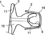
图3是根据第二实施例的与图1相似的植入物视图;Figure 3 is a view of an implant similar to Figure 1 according to a second embodiment;
图4是根据该第二实施例的植入物在植入构造下的视图;Figure 4 is a view of the implant according to this second embodiment in the implanted configuration;
图5是根据第三实施例的与图1相似的植入物视图;Figure 5 is a view of an implant similar to Figure 1 according to a third embodiment;
图6是根据第四实施例的与图1相似的植入物视图。Fig. 6 is a view of an implant similar to Fig. 1 according to a fourth embodiment.
为了简化,一个实施例中的部分或元件若在另一实施例中以相同或相似的方式再次出现,则用相同的附图标记来标示它并将不再对它进行描述。For simplicity, if a part or element in one embodiment appears again in the same or similar manner in another embodiment, it will be marked with the same reference numeral and will not be described again.
具体实施方式Detailed ways
图1和2示出一棘突间植入物1,它适于插入在两个椎骨的棘突之间,以能阻尼这些椎骨在脊柱牵伸过程中的向后运动。植入物1基本上呈H形,也就是说,它包括用于放置在所述棘突之间的中间部件2、界定上凹部4的一对凸伸上臂3以及界定下凹部6的一对凸伸下臂5,这些凹部4和6能接纳两个椎骨的棘突。Figures 1 and 2 show an interspinous implant 1 adapted to be inserted between the spinous processes of two vertebrae in order to damp the backward movement of these vertebrae during spinal distraction. The implant 1 is substantially H-shaped, that is to say it comprises an
如图2所示,臂3和5具有截头的前部上边缘3a和5a,这些上边缘分别倾斜并呈圆角形,以使植入物1可装配在椎骨的棘突的基部处,并尽可能靠近板层。As shown in Figure 2, the
植入物1还包括形成为穿过部件2的管道7,该管道7的端部是外张的。如果需要,该管道7可用来装配穿过其并围绕两椎骨的棘突配合的韧带。The implant 1 also comprises a
植入物1可包括由特别是聚酯的织物材料制成的包覆物,该包膜将其完全包覆住。The implant 1 may comprise a covering made of a textile material, in particular polyester, which encloses it completely.
如图所示,植入物1由不同材料制成的部件形成,即:As shown, the implant 1 is formed from parts made of different materials, namely:
-中心部件10,其由第一可弹性变形材料,例如硬度为65肖氏A的硅酮制成的;以及- a
-两个侧向部件11,其由比所述第一材料更刚性的第二可弹性变形的材料制成,位于中心部件10的相对两侧向侧,也就是说在设计成在植入后纵向位于棘突的每一侧上的那两侧上,这些侧向部件11连接至中心部件10。- two
侧向部件11在植入物1的整个高度上延伸;在图1所示的实施例中,它们的厚度除了在臂3和5的自由端部处变化稍大之外几乎不变化,并且它们在与中心部件10的整个组装界面上与该中心部件紧密结合。它们特别可由肖氏A硬度比中心部件10的材料高的硅酮制成,例如约85肖氏A的材料,并且它们被模制到该中心部件10上。The
这些更刚性的侧向部件11可抵制构成中心部件10的材料在可能由棘突施加在部件2上的高压缩力的作用下发生侧向蠕变的危险,因此为该部件2保存足够的阻尼能力。These more rigid
侧向部件11还具有加强臂3和5的刚度并因而提高植入物1在装配后的在位保持度的效果,特别是在脊柱扭转运动或其侧向弯曲的情况下,以及尤其是在部件2受到明显压缩的情况下。The
图3示出侧向部件11可在植入物1的棘突间中间部分处具有减小的厚度,从而如图4所示,允许位于植入物1同一侧上的臂3和5朝向彼此弯曲,以使得植入物可插入棘突间的空隙。臂3和5可借助于保持连结件15保持在该弯曲的位置。Figure 3 shows that the
图5示出侧向部件11也可通过植入物1的部件2来彼此连接。该部件2于是包括由两个部件11和中间连接部件12构成的元件,中心部件10覆盖模制在该元件上。FIG. 5 shows that the
在这种情况下,连接部件12是管状的,以在需要时允许一根或多根韧带穿过其以相对于椎骨提供对植入物1的附加保持作用。图6示出连接部件12也的横截面也可以是实心的,于是可提高植入物1的棘突间部件的阻尼程度。In this case, the connecting
如从上文中清楚地可见,本发明提供一种棘突间植入物,它由可弹性变形材料块体制成,在任何情况下都具有足够的阻尼能力,尤其是在特别严重的患者或有局部代偿性脊柱前凸过度的那些患者的情况下也具有足够的阻尼能力,并且加强植入物保持在位的作用,这样就可不再需要围绕所治疗的椎骨棘突装配韧带。As is clear from the foregoing, the present invention provides an interspinous implant made of a block of elastically deformable material, which in any case has sufficient damping capacity, especially in particularly severe patients or patients with There is also sufficient damping capacity in the case of those patients with partially compensated hyperlordosis and enhanced implant retention so that ligament fitting around the spinous process of the treated vertebra is no longer required.
无需说,本发明并不局限于以上以举例方式描述的实施例,而可延伸到所附权利要求书所涵盖的所有实施例。It goes without saying that the invention is not limited to the embodiments described above by way of example, but extends to all embodiments covered by the appended claims.
Claims (10)
Translated fromChineseApplications Claiming Priority (5)
| Application Number | Priority Date | Filing Date | Title |
|---|---|---|---|
| US85758906P | 2006-11-08 | 2006-11-08 | |
| US60/857,589 | 2006-11-08 | ||
| FR06/09738 | 2006-11-08 | ||
| FR0609738AFR2908035B1 (en) | 2006-11-08 | 2006-11-08 | INTEREPINE IMPLANT |
| PCT/IB2007/003389WO2008056237A2 (en) | 2006-11-08 | 2007-11-07 | Interspinous implant |
Publications (2)
| Publication Number | Publication Date |
|---|---|
| CN101636117A CN101636117A (en) | 2010-01-27 |
| CN101636117Btrue CN101636117B (en) | 2011-12-28 |
Family
ID=38293964
Family Applications (1)
| Application Number | Title | Priority Date | Filing Date |
|---|---|---|---|
| CN2007800492127AExpired - Fee RelatedCN101636117B (en) | 2006-11-08 | 2007-11-07 | interspinous implant |
Country Status (9)
| Country | Link |
|---|---|
| US (1) | US8118839B2 (en) |
| EP (1) | EP2088949B1 (en) |
| JP (2) | JP2010508934A (en) |
| KR (1) | KR20090108589A (en) |
| CN (1) | CN101636117B (en) |
| AU (1) | AU2007318980A1 (en) |
| FR (1) | FR2908035B1 (en) |
| IL (1) | IL198649A0 (en) |
| WO (1) | WO2008056237A2 (en) |
Families Citing this family (25)
| Publication number | Priority date | Publication date | Assignee | Title |
|---|---|---|---|---|
| WO2010048396A2 (en) | 2008-10-23 | 2010-04-29 | Linares Maedical Devices, Llc | Support insert associated with spinal vertebrae |
| JP2013504389A (en)* | 2009-09-11 | 2013-02-07 | アーティキュリンクス, インコーポレイテッド | Disc-shaped orthopedic device |
| JP2013509959A (en) | 2009-11-06 | 2013-03-21 | ジンテス ゲゼルシャフト ミット ベシュレンクテル ハフツング | Minimally invasive interspinous spacer implant and method |
| US9724140B2 (en) | 2010-06-02 | 2017-08-08 | Wright Medical Technology, Inc. | Tapered, cylindrical cruciform hammer toe implant and method |
| US9498273B2 (en) | 2010-06-02 | 2016-11-22 | Wright Medical Technology, Inc. | Orthopedic implant kit |
| US8608785B2 (en) | 2010-06-02 | 2013-12-17 | Wright Medical Technology, Inc. | Hammer toe implant with expansion portion for retrograde approach |
| US9072564B2 (en) | 2010-06-02 | 2015-07-07 | Wright Medical Technology, Inc. | Hammer toe implant and method |
| KR101066324B1 (en)* | 2011-04-06 | 2011-09-20 | 유창화 | Spinal process spacer |
| US20120323276A1 (en)* | 2011-06-17 | 2012-12-20 | Bryan Okamoto | Expandable interspinous device |
| FR2977139B1 (en) | 2011-06-30 | 2014-08-22 | Ldr Medical | INTER-SPINAL IMPLANT AND IMPLANTATION INSTRUMENT |
| WO2013075053A1 (en)* | 2011-11-17 | 2013-05-23 | Vertiflex Inc. | Interspinous spacers and associated methods of use and manufacture |
| WO2015028853A1 (en) | 2013-08-30 | 2015-03-05 | Newsouth Innovations Pty Limited | Spine stabilization device |
| AU2013308332B2 (en) | 2012-08-31 | 2017-01-19 | Newsouth Innovations Pty Limited | Bone stabilization device and methods of use |
| US8945232B2 (en) | 2012-12-31 | 2015-02-03 | Wright Medical Technology, Inc. | Ball and socket implants for correction of hammer toes and claw toes |
| US9724139B2 (en) | 2013-10-01 | 2017-08-08 | Wright Medical Technology, Inc. | Hammer toe implant and method |
| US9474561B2 (en) | 2013-11-19 | 2016-10-25 | Wright Medical Technology, Inc. | Two-wire technique for installing hammertoe implant |
| US9545274B2 (en) | 2014-02-12 | 2017-01-17 | Wright Medical Technology, Inc. | Intramedullary implant, system, and method for inserting an implant into a bone |
| US9498266B2 (en) | 2014-02-12 | 2016-11-22 | Wright Medical Technology, Inc. | Intramedullary implant, system, and method for inserting an implant into a bone |
| AU2014331633B2 (en) | 2014-09-18 | 2017-06-22 | Wright Medical Technology, Inc | Hammertoe implant and instrument |
| CN105960211B (en) | 2014-12-19 | 2019-01-11 | 瑞特医疗技术公司 | Intramedullary Anchors for Interphalangeal Arthrodesis |
| TWI627935B (en) | 2017-01-24 | 2018-07-01 | 好喜歡妮有限公司 | Interspinous stabilizer |
| EP3863544B1 (en)* | 2018-10-04 | 2023-01-18 | G & G S.R.L. | Improved interlaminar-type intervertebral support device |
| CN213098543U (en) | 2020-06-24 | 2021-05-04 | 好喜欢妮有限公司 | Interspinous process fixing device |
| TWM609706U (en)* | 2020-06-24 | 2021-04-01 | 好喜歡妮有限公司 | Interspinous stabilization device |
| FR3149183B1 (en) | 2023-06-01 | 2025-07-11 | Cousin Biotech | Vertebral implantation system of a vertebral spacer element |
Citations (2)
| Publication number | Priority date | Publication date | Assignee | Title |
|---|---|---|---|---|
| US20050203512A1 (en)* | 2004-03-09 | 2005-09-15 | Depuy Spine, Inc. | Posterior process dynamic spacer |
| WO2006106246A2 (en)* | 2005-04-08 | 2006-10-12 | Spinevision | Surgical intervertebral implant forming a swivel joint |
Family Cites Families (393)
| Publication number | Priority date | Publication date | Assignee | Title |
|---|---|---|---|---|
| US624969A (en) | 1899-05-16 | Peter peterson | ||
| US1153797A (en) | 1915-04-29 | 1915-09-14 | Jules Emile Kegreisz | Expansion-anchor. |
| US1516347A (en) | 1923-08-30 | 1924-11-18 | Pataky Anton | Coupling pin |
| US1870942A (en) | 1928-05-26 | 1932-08-09 | Gynex Corp | Syringe |
| US2077804A (en) | 1936-05-19 | 1937-04-20 | Morrison Gordon Monroe | Device for treating fractures of the neck of the femur |
| US2299308A (en) | 1941-08-15 | 1942-10-20 | Russell A Creighton | Self-locking spike |
| US2485531A (en) | 1948-01-13 | 1949-10-18 | Dzus William | Surgical toggle bolt |
| US2607370A (en) | 1948-07-13 | 1952-08-19 | Oscar F Anderson | Pipe plug |
| US2685877A (en) | 1952-03-20 | 1954-08-10 | Dobelle Martin | Femoral head prosthesis |
| US2677369A (en) | 1952-03-26 | 1954-05-04 | Fred L Knowles | Apparatus for treatment of the spinal column |
| US3065659A (en) | 1959-09-28 | 1962-11-27 | Superior Concrete Accessories | Expansion bolt |
| US3108595A (en) | 1960-08-08 | 1963-10-29 | Alfred P Overment | Retention catheter |
| US3397699A (en) | 1966-05-05 | 1968-08-20 | Gerald C. Kohl | Retaining catheter having resiliently biased wing flanges |
| US3426364A (en) | 1966-08-25 | 1969-02-11 | Colorado State Univ Research F | Prosthetic appliance for replacing one or more natural vertebrae |
| US3648691A (en) | 1970-02-24 | 1972-03-14 | Univ Colorado State Res Found | Method of applying vertebral appliance |
| DE2112139B2 (en) | 1971-03-13 | 1973-02-01 | Fischer, Artur, 7241 Tumhngen | SLEEVE-SHAPED CONNECTOR FOR COMPRESSION OSTEOSYNTHESIS IN TUBE BONE Fractures |
| US4011602A (en) | 1975-10-06 | 1977-03-15 | Battelle Memorial Institute | Porous expandable device for attachment to bone tissue |
| US4704057A (en) | 1976-09-15 | 1987-11-03 | Mechanical Plastics Corp. | Fastening element |
| PL114098B1 (en) | 1978-04-14 | 1981-01-31 | Wyzsza Szkola Inzynierska | Apparatus for correcting spinal curvature |
| US4274324A (en) | 1978-04-18 | 1981-06-23 | Giannuzzi Louis | Hollow wall screw anchor |
| CH628803A5 (en) | 1978-05-12 | 1982-03-31 | Sulzer Ag | Implant insertable between adjacent vertebrae |
| US4237875A (en) | 1979-02-23 | 1980-12-09 | Towmotor Corporation | Dynamic intramedullary compression nailing |
| US4327736A (en) | 1979-11-20 | 1982-05-04 | Kanji Inoue | Balloon catheter |
| US4289123A (en) | 1980-03-31 | 1981-09-15 | Dunn Harold K | Orthopedic appliance |
| GB2083754B (en) | 1980-09-15 | 1984-04-26 | Rezaian Seyed Mahmoud | Spinal fixator |
| SU988281A1 (en) | 1981-06-26 | 1983-01-15 | За витель | Vertical column fixing device |
| US4646998A (en) | 1981-11-20 | 1987-03-03 | Clairson International Corporation | Wall-mounted shelf support clip |
| US4519100A (en) | 1982-09-30 | 1985-05-28 | Orthopedic Equipment Co. Inc. | Distal locking intramedullary nail |
| US4499636A (en) | 1983-05-06 | 1985-02-19 | Nifco Inc. | Removable two-piece retaining means |
| US4822226A (en) | 1983-08-08 | 1989-04-18 | Kennedy Arvest G | Wing nut retainer and extractor |
| US4554914A (en) | 1983-10-04 | 1985-11-26 | Kapp John P | Prosthetic vertebral body |
| US4553273A (en) | 1983-11-23 | 1985-11-19 | Henry Ford Hospital | Vertebral body prosthesis and spine stabilizing method |
| GB8333442D0 (en) | 1983-12-15 | 1984-01-25 | Showell A W Sugicraft Ltd | Devices for spinal fixation |
| US4611582A (en) | 1983-12-27 | 1986-09-16 | Wisconsin Alumni Research Foundation | Vertebral clamp |
| US4604995A (en) | 1984-03-30 | 1986-08-12 | Stephens David C | Spinal stabilizer |
| US4573454A (en) | 1984-05-17 | 1986-03-04 | Hoffman Gregory A | Spinal fixation apparatus |
| JPS60187737U (en) | 1984-05-23 | 1985-12-12 | オリンパス光学工業株式会社 | Indwelling tube guide device |
| FR2575059B1 (en) | 1984-12-21 | 1988-11-10 | Daher Youssef | SHORING DEVICE FOR USE IN A VERTEBRAL PROSTHESIS |
| US4721103A (en) | 1985-01-31 | 1988-01-26 | Yosef Freedland | Orthopedic device |
| US4632101A (en) | 1985-01-31 | 1986-12-30 | Yosef Freedland | Orthopedic fastener |
| US4636217A (en) | 1985-04-23 | 1987-01-13 | Regents Of The University Of Minnesota | Anterior spinal implant |
| US4599086A (en) | 1985-06-07 | 1986-07-08 | Doty James R | Spine stabilization device and method |
| SE458417B (en) | 1985-08-15 | 1989-04-03 | Sven Olerud | FIXING INSTRUMENTS PROVIDED FOR USE IN SPINE OPERATIONS |
| US4662808A (en) | 1985-10-02 | 1987-05-05 | Lee-Rowan Company | Wall anchor |
| US4931055A (en) | 1986-05-30 | 1990-06-05 | John Bumpus | Distraction rods |
| GB8620937D0 (en) | 1986-08-29 | 1986-10-08 | Shepperd J A N | Spinal implant |
| US4787378A (en) | 1986-09-08 | 1988-11-29 | Sodhi Jitendra S | Self-retaining nail for fracture of neck of femur |
| US4969887A (en) | 1986-09-08 | 1990-11-13 | Sodhi Jitendra S | Self-retaining nail kit for repairing a fractured neck of femur |
| CA1283501C (en) | 1987-02-12 | 1991-04-30 | Thomas P. Hedman | Artificial spinal disc |
| SU1484348A1 (en) | 1987-03-04 | 1989-06-07 | Белорусский научно-исследовательский институт травматологии и ортопедии | Spinal column fixing device |
| FR2623085B1 (en) | 1987-11-16 | 1992-08-14 | Breard Francis | SURGICAL IMPLANT TO LIMIT THE RELATIVE MOVEMENT OF VERTEBRES |
| FR2625097B1 (en) | 1987-12-23 | 1990-05-18 | Cote Sarl | INTER-SPINOUS PROSTHESIS COMPOSED OF SEMI-ELASTIC MATERIAL COMPRISING A TRANSFILING EYE AT ITS END AND INTER-SPINOUS PADS |
| CH674709A5 (en) | 1988-04-27 | 1990-07-13 | Sulzer Ag | |
| US5609635A (en) | 1988-06-28 | 1997-03-11 | Michelson; Gary K. | Lordotic interbody spinal fusion implants |
| US4892545A (en) | 1988-07-14 | 1990-01-09 | Ohio Medical Instrument Company, Inc. | Vertebral lock |
| IT215084Z2 (en) | 1988-08-03 | 1990-07-30 | Torino A | VARIABLE EXCURSION CAMBRA |
| US4834600A (en) | 1988-08-25 | 1989-05-30 | Lemke Stuart H | Fastener assembly |
| GB8825909D0 (en) | 1988-11-04 | 1988-12-07 | Showell A W Sugicraft Ltd | Pedicle engaging means |
| US5201734A (en) | 1988-12-21 | 1993-04-13 | Zimmer, Inc. | Spinal locking sleeve assembly |
| US4886405A (en) | 1989-01-27 | 1989-12-12 | Blomberg Ingvar M | Wall mounting device |
| FR2642645B1 (en) | 1989-02-03 | 1992-08-14 | Breard Francis | FLEXIBLE INTERVERTEBRAL STABILIZER AND METHOD AND APPARATUS FOR CONTROLLING ITS VOLTAGE BEFORE PLACEMENT ON THE RACHIS |
| US5098433A (en) | 1989-04-12 | 1992-03-24 | Yosef Freedland | Winged compression bolt orthopedic fastener |
| DE3922044A1 (en) | 1989-07-05 | 1991-02-07 | Richter Turtur Matthias Dr | Treatment of fractured vertebra - by instrument which avoids any force on intact adjacent to vertebrae |
| US4932975A (en) | 1989-10-16 | 1990-06-12 | Vanderbilt University | Vertebral prosthesis |
| US5059193A (en) | 1989-11-20 | 1991-10-22 | Spine-Tech, Inc. | Expandable spinal implant and surgical method |
| US5345927A (en) | 1990-03-02 | 1994-09-13 | Bonutti Peter M | Arthroscopic retractors |
| US5454365A (en) | 1990-11-05 | 1995-10-03 | Bonutti; Peter M. | Mechanically expandable arthroscopic retractors |
| DE4012622C1 (en) | 1990-04-20 | 1991-07-18 | Eska Medical Luebeck Medizintechnik Gmbh & Co, 2400 Luebeck, De | Two-part metal vertebra implant - has parts locked by two toothed racks, pre-stressed by elastic cushion between both implant parts |
| US5047055A (en) | 1990-12-21 | 1991-09-10 | Pfizer Hospital Products Group, Inc. | Hydrogel intervertebral disc nucleus |
| US5356423A (en) | 1991-01-04 | 1994-10-18 | American Medical Systems, Inc. | Resectable self-expanding stent |
| US5390683A (en) | 1991-02-22 | 1995-02-21 | Pisharodi; Madhavan | Spinal implantation methods utilizing a middle expandable implant |
| US5171278A (en) | 1991-02-22 | 1992-12-15 | Madhavan Pisharodi | Middle expandable intervertebral disk implants |
| DE69209494T2 (en) | 1991-02-22 | 1996-10-31 | Pisharodi Madhavan | IMPLANT FROM AN EXPANDABLE INTERMEDIATE DISC |
| SE470047B (en) | 1991-05-15 | 1993-11-01 | Sven Olerud | Clamp jaw intended for surgical use |
| DE4128332A1 (en) | 1991-08-27 | 1993-03-04 | Man Ceramics Gmbh | SPINE BONE REPLACEMENT |
| US5290312A (en) | 1991-09-03 | 1994-03-01 | Alphatec | Artificial vertebral body |
| FR2681525A1 (en) | 1991-09-19 | 1993-03-26 | Medical Op | Device for flexible or semi-rigid stabilisation of the spine, in particular of the human spine, by a posterior route |
| CH686610A5 (en) | 1991-10-18 | 1996-05-15 | Pina Vertriebs Ag | Compression implant. |
| DE4208116C2 (en) | 1992-03-13 | 1995-08-03 | Link Waldemar Gmbh Co | Intervertebral disc prosthesis |
| EP0566810B1 (en) | 1992-04-21 | 1996-08-14 | SULZER Medizinaltechnik AG | Artificial spinal disc |
| US5316422A (en) | 1992-06-01 | 1994-05-31 | Qualcomm Incorporated | Blind fastener |
| US5312405A (en) | 1992-07-06 | 1994-05-17 | Zimmer, Inc. | Spinal rod coupler |
| FR2693364B1 (en) | 1992-07-07 | 1995-06-30 | Erpios Snc | INTERVERTEBRAL PROSTHESIS FOR STABILIZING ROTATORY AND FLEXIBLE-EXTENSION CONSTRAINTS. |
| FR2695026B1 (en) | 1992-08-25 | 1994-10-28 | Alexandre Worcel | Device for maintaining compression of a fractured bone. |
| DE9213656U1 (en) | 1992-10-09 | 1992-12-03 | Angiomed AG, 7500 Karlsruhe | Stent set |
| US5562735A (en) | 1992-11-09 | 1996-10-08 | Hospital For Joint Diseases | Spinal stabilization system and improved method |
| US5702395A (en) | 1992-11-10 | 1997-12-30 | Sofamor S.N.C. | Spine osteosynthesis instrumentation for an anterior approach |
| ATE206602T1 (en) | 1992-11-12 | 2001-10-15 | Neville Alleyne | DEVICE FOR PROTECTING THE HEART |
| US5306275A (en) | 1992-12-31 | 1994-04-26 | Bryan Donald W | Lumbar spine fixation apparatus and method |
| US5527314A (en) | 1993-01-04 | 1996-06-18 | Danek Medical, Inc. | Spinal fixation system |
| US5540703A (en) | 1993-01-06 | 1996-07-30 | Smith & Nephew Richards Inc. | Knotted cable attachment apparatus formed of braided polymeric fibers |
| US5496318A (en) | 1993-01-08 | 1996-03-05 | Advanced Spine Fixation Systems, Inc. | Interspinous segmental spine fixation device |
| FR2700941A1 (en) | 1993-02-03 | 1994-08-05 | Felman Daniel | Monobloc interspinal intervertebral fixation implant |
| US5415661A (en) | 1993-03-24 | 1995-05-16 | University Of Miami | Implantable spinal assist device |
| FR2703239B1 (en) | 1993-03-30 | 1995-06-02 | Brio Bio Rhone Implant Medical | Clip for interspinous prosthesis. |
| EP0621020A1 (en) | 1993-04-21 | 1994-10-26 | SULZER Medizinaltechnik AG | Intervertebral prosthesis and method of implanting such a prosthesis |
| DE4417629B4 (en) | 1993-06-24 | 2006-03-16 | SDGI Holdings, Inc., Wilmington | Implant for the replacement of vertebral bodies |
| FR2707864B1 (en) | 1993-07-23 | 1996-07-19 | Jean Taylor | Surgical forceps for tensioning an osteosynthesis ligament. |
| US5360430A (en) | 1993-07-29 | 1994-11-01 | Lin Chih I | Intervertebral locking device |
| US5458641A (en) | 1993-09-08 | 1995-10-17 | Ramirez Jimenez; Juan J. | Vertebral body prosthesis |
| US5456689A (en) | 1993-10-13 | 1995-10-10 | Arnold J. Kresch | Method and device for tissue resection |
| US5439463A (en) | 1993-11-12 | 1995-08-08 | Lin; Chih-I | Spinal clamping device |
| US5454812A (en) | 1993-11-12 | 1995-10-03 | Lin; Chih-I | Spinal clamping device having multiple distance adjusting strands |
| US5403316A (en) | 1993-12-02 | 1995-04-04 | Danek Medical, Inc. | Triangular construct for spinal fixation |
| FR2715293B1 (en) | 1994-01-26 | 1996-03-22 | Biomat | Vertebral interbody fusion cage. |
| US5653762A (en) | 1994-03-18 | 1997-08-05 | Pisharodi; Madhavan | Method of stabilizing adjacent vertebrae with rotating, lockable, middle-expanded intervertebral disk stabilizer |
| FR2717675B1 (en) | 1994-03-24 | 1996-05-03 | Jean Taylor | Interspinous wedge. |
| FR2719763B1 (en) | 1994-05-11 | 1996-09-27 | Jean Taylor | Vertebral implant. |
| FR2721501B1 (en) | 1994-06-24 | 1996-08-23 | Fairant Paulette | Prostheses of the vertebral articular facets. |
| DE4423257C2 (en) | 1994-07-02 | 2001-07-12 | Ulrich Heinrich | Implant to be inserted between the vertebral body of the spine as a placeholder |
| FR2722088B1 (en) | 1994-07-08 | 1998-01-23 | Cahlik Marc Andre | SURGICAL IMPLANT FOR STABILIZING THE INTERVERTEBRAL SPACE |
| FR2722087A1 (en) | 1994-07-08 | 1996-01-12 | Cahlik Marc Andre | Surgical implant for limiting relative movement of vertebrae |
| FR2722980B1 (en) | 1994-07-26 | 1996-09-27 | Samani Jacques | INTERTEPINOUS VERTEBRAL IMPLANT |
| DE9413471U1 (en) | 1994-08-20 | 1995-12-21 | Schäfer micomed GmbH, 73614 Schorndorf | Ventral intervertebral implant |
| ATE203885T1 (en) | 1994-09-08 | 2001-08-15 | Stryker Technologies Corp | HYDROGEL DISC CORE |
| FR2724554B1 (en) | 1994-09-16 | 1997-01-24 | Voydeville Gilles | DEVICE FOR FIXING A LIGAMENT PROSTHESIS |
| JPH10507386A (en) | 1994-10-17 | 1998-07-21 | レイメディカ, インコーポレイテッド | Artificial spinal disc nucleus |
| FR2725892A1 (en) | 1994-10-21 | 1996-04-26 | Felman Daniel | Vertebral implant insertion process using shape memory material |
| FR2728159B1 (en) | 1994-12-16 | 1997-06-27 | Tornier Sa | ELASTIC DISC PROSTHESIS |
| FR2729556B1 (en) | 1995-01-23 | 1998-10-16 | Sofamor | SPINAL OSTEOSYNTHESIS DEVICE WITH MEDIAN HOOK AND VERTEBRAL ANCHOR SUPPORT |
| US5665122A (en) | 1995-01-31 | 1997-09-09 | Kambin; Parviz | Expandable intervertebral cage and surgical method |
| FR2730156B1 (en) | 1995-02-03 | 1997-04-30 | Textile Hi Tec | INTER SPINOUS HOLD |
| FR2730158B1 (en) | 1995-02-06 | 1999-11-26 | Jbs Sa | DEVICE FOR MAINTAINING A NORMAL SPACING BETWEEN VERTEBRES AND FOR THE REPLACEMENT OF MISSING VERTEBRES |
| US5658335A (en) | 1995-03-09 | 1997-08-19 | Cohort Medical Products Group, Inc. | Spinal fixator |
| FR2731643A1 (en) | 1995-03-16 | 1996-09-20 | Jbs Sa | ANGULAR SCREWDRIVER DEVICE FOR SCREWING IN AND SCREWING DIFFICULT ACCESSIBLE SCREWS, PARTICULARLY IN THE SURGICAL FIELD |
| US5630816A (en) | 1995-05-01 | 1997-05-20 | Kambin; Parviz | Double barrel spinal fixation system and method |
| WO1996039090A1 (en) | 1995-06-06 | 1996-12-12 | Sdgi Holdings, Inc. | Device for linking adjacent rods in spinal instrumentation |
| US6102922A (en) | 1995-09-22 | 2000-08-15 | Kirk Promotions Limited | Surgical method and device for reducing the food intake of patient |
| US5690649A (en) | 1995-12-05 | 1997-11-25 | Li Medical Technologies, Inc. | Anchor and anchor installation tool and method |
| DE19603887C2 (en) | 1996-02-03 | 1998-07-02 | Lerch Karl Dieter | Arrangement for fixing a piece of bone that has been removed from the skull capsule for the purpose of the surgical intervention to the remaining skull leg |
| US5653763A (en) | 1996-03-29 | 1997-08-05 | Fastenetix, L.L.C. | Intervertebral space shape conforming cage device |
| EP0845965A1 (en) | 1996-06-18 | 1998-06-10 | Mehran Kasra | Bone prosthesis fixation device and methods of using same |
| US5746762A (en) | 1996-06-24 | 1998-05-05 | Bass; Lawrence S. | Device and method for surgical flap dissection |
| US5702455A (en) | 1996-07-03 | 1997-12-30 | Saggar; Rahul | Expandable prosthesis for spinal fusion |
| US5849004A (en) | 1996-07-17 | 1998-12-15 | Bramlet; Dale G. | Surgical anchor |
| US5716416A (en) | 1996-09-10 | 1998-02-10 | Lin; Chih-I | Artificial intervertebral disk and method for implanting the same |
| US5810815A (en) | 1996-09-20 | 1998-09-22 | Morales; Jose A. | Surgical apparatus for use in the treatment of spinal deformities |
| US6190414B1 (en) | 1996-10-31 | 2001-02-20 | Surgical Dynamics Inc. | Apparatus for fusion of adjacent bone structures |
| US5893850A (en) | 1996-11-12 | 1999-04-13 | Cachia; Victor V. | Bone fixation device |
| DE19652608C1 (en) | 1996-12-18 | 1998-08-27 | Eska Implants Gmbh & Co | Prophylaxis implant against fractures of osteoporotically affected bone segments |
| US7101375B2 (en) | 1997-01-02 | 2006-09-05 | St. Francis Medical Technologies, Inc. | Spine distraction implant |
| US5860977A (en) | 1997-01-02 | 1999-01-19 | Saint Francis Medical Technologies, Llc | Spine distraction implant and method |
| US6451019B1 (en) | 1998-10-20 | 2002-09-17 | St. Francis Medical Technologies, Inc. | Supplemental spine fixation device and method |
| US7201751B2 (en) | 1997-01-02 | 2007-04-10 | St. Francis Medical Technologies, Inc. | Supplemental spine fixation device |
| US20050245937A1 (en) | 2004-04-28 | 2005-11-03 | St. Francis Medical Technologies, Inc. | System and method for insertion of an interspinous process implant that is rotatable in order to retain the implant relative to the spinous processes |
| US6514256B2 (en) | 1997-01-02 | 2003-02-04 | St. Francis Medical Technologies, Inc. | Spine distraction implant and method |
| US7959652B2 (en) | 2005-04-18 | 2011-06-14 | Kyphon Sarl | Interspinous process implant having deployable wings and method of implantation |
| US20020143331A1 (en) | 1998-10-20 | 2002-10-03 | Zucherman James F. | Inter-spinous process implant and method with deformable spacer |
| US6695842B2 (en) | 1997-10-27 | 2004-02-24 | St. Francis Medical Technologies, Inc. | Interspinous process distraction system and method with positionable wing and method |
| US7306628B2 (en) | 2002-10-29 | 2007-12-11 | St. Francis Medical Technologies | Interspinous process apparatus and method with a selectably expandable spacer |
| US5836948A (en) | 1997-01-02 | 1998-11-17 | Saint Francis Medical Technologies, Llc | Spine distraction implant and method |
| US6068630A (en) | 1997-01-02 | 2000-05-30 | St. Francis Medical Technologies, Inc. | Spine distraction implant |
| US5725341A (en) | 1997-01-08 | 1998-03-10 | Hofmeister; Oskar | Self fusing fastener |
| WO2001054598A1 (en) | 1998-03-06 | 2001-08-02 | Disc-O-Tech Medical Technologies, Ltd. | Expanding bone implants |
| WO2004110300A2 (en) | 2001-07-25 | 2004-12-23 | Disc Orthopaedic Technologies Inc. | Deformable tools and implants |
| US20070282443A1 (en) | 1997-03-07 | 2007-12-06 | Disc-O-Tech Medical Technologies Ltd. | Expandable element |
| EP1905392B1 (en) | 1997-03-07 | 2011-05-18 | Kyphon SÀRL | System for percutaneous bone and spinal stabilization, fixation and repair |
| IL128261A0 (en) | 1999-01-27 | 1999-11-30 | Disc O Tech Medical Tech Ltd | Expandable element |
| US6022376A (en) | 1997-06-06 | 2000-02-08 | Raymedica, Inc. | Percutaneous prosthetic spinal disc nucleus and method of manufacture |
| EP1867293A2 (en) | 1997-10-27 | 2007-12-19 | St. Francis Medical Technologies, Inc. | Spine distraction implant |
| US5980523A (en) | 1998-01-08 | 1999-11-09 | Jackson; Roger | Transverse connectors for spinal rods |
| US5941881A (en) | 1998-01-09 | 1999-08-24 | Medidea, Llc | Bone fastening apparatus and related procedures |
| FR2774581B1 (en) | 1998-02-10 | 2000-08-11 | Dimso Sa | INTEREPINOUS STABILIZER TO BE ATTACHED TO SPINOUS APOPHYSIS OF TWO VERTEBRES |
| FR2775183B1 (en) | 1998-02-20 | 2000-08-04 | Jean Taylor | INTER-SPINOUS PROSTHESIS |
| DE19816782A1 (en) | 1998-04-16 | 1999-10-28 | Ulrich Gmbh & Co Kg | Implant for insertion between the vertebral body of the spine |
| DE19818143A1 (en) | 1998-04-23 | 1999-10-28 | Medinorm Ag | Device for connecting vertebrae of the spine |
| US6126689A (en) | 1998-06-15 | 2000-10-03 | Expanding Concepts, L.L.C. | Collapsible and expandable interbody fusion device |
| US6264658B1 (en) | 1998-07-06 | 2001-07-24 | Solco Surgical Instruments Co., Ltd. | Spine fixing apparatus |
| FR2782632B1 (en) | 1998-08-28 | 2000-12-29 | Materiel Orthopedique En Abreg | EXPANSIBLE INTERSOMATIC FUSION CAGE |
| US6352537B1 (en) | 1998-09-17 | 2002-03-05 | Electro-Biology, Inc. | Method and apparatus for spinal fixation |
| US7029473B2 (en) | 1998-10-20 | 2006-04-18 | St. Francis Medical Technologies, Inc. | Deflectable spacer for use as an interspinous process implant and method |
| US6554833B2 (en) | 1998-10-26 | 2003-04-29 | Expanding Orthopedics, Inc. | Expandable orthopedic device |
| US6261289B1 (en) | 1998-10-26 | 2001-07-17 | Mark Levy | Expandable orthopedic device |
| ATE322868T1 (en) | 1998-10-30 | 2006-04-15 | Ian Ross Griggs | FIXATION DEVICE |
| BR9805340B1 (en) | 1998-12-14 | 2009-01-13 | variable expansion insert for spinal stabilization. | |
| US7621950B1 (en) | 1999-01-27 | 2009-11-24 | Kyphon Sarl | Expandable intervertebral spacer |
| US6214037B1 (en) | 1999-03-18 | 2001-04-10 | Fossa Industries, Llc | Radially expanding stent |
| US6520991B2 (en) | 1999-05-11 | 2003-02-18 | Donald R. Huene | Expandable implant for inter-vertebral stabilization, and a method of stabilizing vertebrae |
| US6214050B1 (en) | 1999-05-11 | 2001-04-10 | Donald R. Huene | Expandable implant for inter-bone stabilization and adapted to extrude osteogenic material, and a method of stabilizing bones while extruding osteogenic material |
| US6245107B1 (en) | 1999-05-28 | 2001-06-12 | Bret A. Ferree | Methods and apparatus for treating disc herniation |
| US6419704B1 (en) | 1999-10-08 | 2002-07-16 | Bret Ferree | Artificial intervertebral disc replacement methods and apparatus |
| US6770096B2 (en) | 1999-07-01 | 2004-08-03 | Spinevision S.A. | Interbody spinal stabilization cage and spinal stabilization method |
| US7815590B2 (en) | 1999-08-05 | 2010-10-19 | Broncus Technologies, Inc. | Devices for maintaining patency of surgically created channels in tissue |
| CA2425951C (en) | 1999-08-18 | 2008-09-16 | Intrinsic Therapeutics, Inc. | Devices and method for nucleus pulposus augmentation and retention |
| US6964674B1 (en) | 1999-09-20 | 2005-11-15 | Nuvasive, Inc. | Annulotomy closure device |
| FR2799640B1 (en) | 1999-10-15 | 2002-01-25 | Spine Next Sa | IMPLANT INTERVETEBRAL |
| US6974478B2 (en) | 1999-10-22 | 2005-12-13 | Archus Orthopedics, Inc. | Prostheses, systems and methods for replacement of natural facet joints with artificial facet joint surfaces |
| FR2799948B1 (en) | 1999-10-22 | 2002-03-29 | Transco Esquisse | CONNECTION BAR FOR ANCHORING AN INTER-THINNING PROSTHESIS |
| ATE285207T1 (en) | 1999-10-22 | 2005-01-15 | Archus Orthopedics Inc | FACET ARTHROPLASTY DEVICES |
| CA2391062C (en) | 1999-11-11 | 2008-01-08 | Synthes (U.S.A.) | Radially expandable intramedullary nail |
| AU7862200A (en) | 2000-01-03 | 2001-07-16 | Y. Freedland | Flip-wing tissue retainer |
| US6293949B1 (en) | 2000-03-01 | 2001-09-25 | Sdgi Holdings, Inc. | Superelastic spinal stabilization system and method |
| US6336930B1 (en) | 2000-03-07 | 2002-01-08 | Zimmer, Inc. | Polymer filled bone plate |
| FR2806616B1 (en) | 2000-03-21 | 2003-04-11 | Cousin Biotech | INTERPINEUSE SHIM AND FASTENING DEVICE ON THE SACRUM |
| US6402750B1 (en) | 2000-04-04 | 2002-06-11 | Spinlabs, Llc | Devices and methods for the treatment of spinal disorders |
| US6432130B1 (en) | 2000-04-20 | 2002-08-13 | Scimed Life Systems, Inc. | Fully sheathed balloon expandable stent delivery system |
| US6645207B2 (en) | 2000-05-08 | 2003-11-11 | Robert A. Dixon | Method and apparatus for dynamized spinal stabilization |
| US6964667B2 (en) | 2000-06-23 | 2005-11-15 | Sdgi Holdings, Inc. | Formed in place fixation system with thermal acceleration |
| FR2811540B1 (en)* | 2000-07-12 | 2003-04-25 | Spine Next Sa | IMPORTING INTERVERTEBRAL IMPLANT |
| US6511508B1 (en) | 2000-08-04 | 2003-01-28 | Environmental Robots, Inc. | Surgical correction of human eye refractive errors by active composite artificial muscle implants |
| US6447546B1 (en) | 2000-08-11 | 2002-09-10 | Dale G. Bramlet | Apparatus and method for fusing opposing spinal vertebrae |
| US6733531B1 (en) | 2000-10-20 | 2004-05-11 | Sdgi Holdings, Inc. | Anchoring devices and implants for intervertebral disc augmentation |
| WO2002047587A2 (en) | 2000-10-25 | 2002-06-20 | Sdgi Holdings, Inc. | Vertically expanding intervertebral body fusion device |
| US6582467B1 (en) | 2000-10-31 | 2003-06-24 | Vertelink Corporation | Expandable fusion cage |
| FR2816197B1 (en)* | 2000-11-07 | 2003-01-10 | Jean Taylor | INTER-SPINABLE PROSTHESIS, TOOL AND PROCESS FOR PREPARING THE SAME |
| US6666891B2 (en) | 2000-11-13 | 2003-12-23 | Frank H. Boehm, Jr. | Device and method for lumbar interbody fusion |
| US6579319B2 (en) | 2000-11-29 | 2003-06-17 | Medicinelodge, Inc. | Facet joint replacement |
| US6419703B1 (en) | 2001-03-01 | 2002-07-16 | T. Wade Fallin | Prosthesis for the replacement of a posterior element of a vertebra |
| US6743257B2 (en) | 2000-12-19 | 2004-06-01 | Cortek, Inc. | Dynamic implanted intervertebral spacer |
| FR2818530B1 (en) | 2000-12-22 | 2003-10-31 | Spine Next Sa | INTERVERTEBRAL IMPLANT WITH DEFORMABLE SHIM |
| GB0102141D0 (en) | 2001-01-27 | 2001-03-14 | Davies John B C | Improvements in or relating to expandable bone nails |
| US6364883B1 (en) | 2001-02-23 | 2002-04-02 | Albert N. Santilli | Spinous process clamp for spinal fusion and method of operation |
| FR2822051B1 (en) | 2001-03-13 | 2004-02-27 | Spine Next Sa | INTERVERTEBRAL IMPLANT WITH SELF-LOCKING ATTACHMENT |
| US6582433B2 (en) | 2001-04-09 | 2003-06-24 | St. Francis Medical Technologies, Inc. | Spine fixation device and method |
| WO2003007829A1 (en) | 2001-07-20 | 2003-01-30 | Spinal Concepts, Inc. | Spinal stabilization system and method |
| US6375682B1 (en) | 2001-08-06 | 2002-04-23 | Lewis W. Fleischmann | Collapsible, rotatable and expandable spinal hydraulic prosthetic device |
| FR2828398B1 (en)* | 2001-08-08 | 2003-09-19 | Jean Taylor | VERTEBRA STABILIZATION ASSEMBLY |
| SK1002004A3 (en) | 2001-08-20 | 2004-08-03 | Synthes Ag | Interspinal prosthesis |
| EP1287794B1 (en) | 2001-08-24 | 2008-06-18 | Zimmer GmbH | Artificial spinal disc |
| US6736815B2 (en) | 2001-09-06 | 2004-05-18 | Core Medical, Inc. | Apparatus and methods for treating spinal discs |
| JP4539900B2 (en) | 2001-09-12 | 2010-09-08 | Hoya株式会社 | Atlantoaxial fixation spacer |
| US20030114853A1 (en) | 2001-10-12 | 2003-06-19 | Ian Burgess | Polyaxial cross connector |
| FR2832917B1 (en) | 2001-11-30 | 2004-09-24 | Spine Next Sa | ELASTICALLY DEFORMABLE INTERVERTEBRAL IMPLANT |
| WO2003051212A2 (en) | 2001-12-13 | 2003-06-26 | Sdgi Holdings, Inc. | Instrumentation and method for delivering an implant into a vertebral space |
| US6656155B2 (en) | 2001-12-17 | 2003-12-02 | Scimed Life Systems, Inc. | Catheter for endoluminal delivery of therapeutic agents that minimizes loss of therapeutic |
| AU2002360783A1 (en) | 2001-12-27 | 2003-07-24 | Osteotech Inc. | Orthopedic/neurosurgical system and method for securing vertebral bone facets |
| FR2835173B1 (en) | 2002-01-28 | 2004-11-05 | Biomet Merck France | INTERTEPINEOUS VERTEBRAL IMPLANT |
| US6733534B2 (en) | 2002-01-29 | 2004-05-11 | Sdgi Holdings, Inc. | System and method for spine spacing |
| US6923830B2 (en) | 2002-02-02 | 2005-08-02 | Gary K. Michelson | Spinal fusion implant having deployable bone engaging projections |
| JP3708883B2 (en) | 2002-02-08 | 2005-10-19 | 昭和医科工業株式会社 | Vertebral space retainer |
| US6669729B2 (en) | 2002-03-08 | 2003-12-30 | Kingsley Richard Chin | Apparatus and method for the replacement of posterior vertebral elements |
| US6808538B2 (en) | 2002-03-15 | 2004-10-26 | Stryker Spine | Vertebral body spacer having variable wedged endplates |
| EP1346708A1 (en) | 2002-03-20 | 2003-09-24 | A-Spine Holding Group Corp. | Three-hooked device for fixing spinal column |
| US7717959B2 (en) | 2002-03-30 | 2010-05-18 | Lytton William | Intervertebral device and method of use |
| US7048736B2 (en) | 2002-05-17 | 2006-05-23 | Sdgi Holdings, Inc. | Device for fixation of spinous processes |
| US20030220643A1 (en) | 2002-05-24 | 2003-11-27 | Ferree Bret A. | Devices to prevent spinal extension |
| PT1540184E (en)* | 2002-06-03 | 2015-08-20 | M & M Technologies Inc | Gear pump |
| US7070598B2 (en) | 2002-06-25 | 2006-07-04 | Sdgi Holdings, Inc. | Minimally invasive expanding spacer and method |
| US7087055B2 (en) | 2002-06-25 | 2006-08-08 | Sdgi Holdings, Inc. | Minimally invasive expanding spacer and method |
| US8317798B2 (en) | 2002-06-25 | 2012-11-27 | Warsaw Orthopedic | Minimally invasive expanding spacer and method |
| US20040010312A1 (en) | 2002-07-09 | 2004-01-15 | Albert Enayati | Intervertebral prosthesis |
| US20040087947A1 (en) | 2002-08-28 | 2004-05-06 | Roy Lim | Minimally invasive expanding spacer and method |
| FR2844179B1 (en)* | 2002-09-10 | 2004-12-03 | Jean Taylor | POSTERIOR VERTEBRAL SUPPORT KIT |
| US7931674B2 (en) | 2005-03-21 | 2011-04-26 | Kyphon Sarl | Interspinous process implant having deployable wing and method of implantation |
| US7549999B2 (en) | 2003-05-22 | 2009-06-23 | Kyphon Sarl | Interspinous process distraction implant and method of implantation |
| US7833246B2 (en) | 2002-10-29 | 2010-11-16 | Kyphon SÀRL | Interspinous process and sacrum implant and method |
| US20060064165A1 (en) | 2004-09-23 | 2006-03-23 | St. Francis Medical Technologies, Inc. | Interspinous process implant including a binder and method of implantation |
| US6723126B1 (en) | 2002-11-01 | 2004-04-20 | Sdgi Holdings, Inc. | Laterally expandable cage |
| US6685742B1 (en) | 2002-11-12 | 2004-02-03 | Roger P. Jackson | Articulated anterior expandable spinal fusion cage system |
| WO2004047689A1 (en) | 2002-11-21 | 2004-06-10 | Sdgi Holdings, Inc. | Systems and techniques for intravertebral spinal stablization with expandable devices |
| AU2003298670A1 (en) | 2002-11-21 | 2004-06-18 | Sdgi Holdings, Inc. | Systems and techniques for intravertebral spinal stabilization with expandable devices |
| FR2850009B1 (en) | 2003-01-20 | 2005-12-23 | Spine Next Sa | TREATMENT ASSEMBLY FOR THE DEGENERATION OF AN INTERVERTEBRAL DISC |
| US20040186577A1 (en) | 2003-01-29 | 2004-09-23 | Ferree Bret A. | In situ artificaial disc replacements and other prosthetic components |
| US7335203B2 (en) | 2003-02-12 | 2008-02-26 | Kyphon Inc. | System and method for immobilizing adjacent spinous processes |
| FR2851154B1 (en) | 2003-02-19 | 2006-07-07 | Sdgi Holding Inc | INTER-SPINOUS DEVICE FOR BRAKING THE MOVEMENTS OF TWO SUCCESSIVE VERTEBRATES, AND METHOD FOR MANUFACTURING THE SAME THEREOF |
| US20050049590A1 (en) | 2003-03-07 | 2005-03-03 | Neville Alleyne | Spinal implant with securement spikes |
| US7824444B2 (en) | 2003-03-20 | 2010-11-02 | Spineco, Inc. | Expandable spherical spinal implant |
| ITFI20030084A1 (en) | 2003-03-28 | 2004-09-29 | Cousin Biotech S A S | INTERLAMINARY VERTEBRAL PROSTHESIS |
| KR100582768B1 (en) | 2003-07-24 | 2006-05-23 | 최병관 | Prostheses for spinal spine insertion |
| CN2638760Y (en) | 2003-08-04 | 2004-09-08 | 邹德威 | Dilator for forming cavity in pyramid |
| US7377942B2 (en) | 2003-08-06 | 2008-05-27 | Warsaw Orthopedic, Inc. | Posterior elements motion restoring device |
| US20050085814A1 (en) | 2003-10-21 | 2005-04-21 | Sherman Michael C. | Dynamizable orthopedic implants and their use in treating bone defects |
| EP1675513B8 (en) | 2003-10-24 | 2013-07-10 | Cousin Biotech, S.A.S. | Inter-blade support |
| DE602004006709T2 (en) | 2003-11-07 | 2008-02-07 | Impliant Ltd. | SPINE GRAFT |
| AU2003304546A1 (en) | 2003-11-10 | 2005-06-08 | Umc Utrecht Holding B.V. | Expandable implant for treating fractured and/or collapsed bone |
| US7217293B2 (en) | 2003-11-21 | 2007-05-15 | Warsaw Orthopedic, Inc. | Expandable spinal implant |
| US20050165398A1 (en) | 2004-01-26 | 2005-07-28 | Reiley Mark A. | Percutaneous spine distraction implant systems and methods |
| US7641664B2 (en) | 2004-02-12 | 2010-01-05 | Warsaw Orthopedic, Inc. | Surgical instrumentation and method for treatment of a spinal structure |
| US8636802B2 (en) | 2004-03-06 | 2014-01-28 | DePuy Synthes Products, LLC | Dynamized interspinal implant |
| DE102004011685A1 (en) | 2004-03-09 | 2005-09-29 | Biedermann Motech Gmbh | Spine supporting element, comprising spiraled grooves at outer surface and three plain areas |
| US7458981B2 (en) | 2004-03-09 | 2008-12-02 | The Board Of Trustees Of The Leland Stanford Junior University | Spinal implant and method for restricting spinal flexion |
| US7507241B2 (en) | 2004-04-05 | 2009-03-24 | Expanding Orthopedics Inc. | Expandable bone device |
| FR2870107B1 (en) | 2004-05-11 | 2007-07-27 | Spine Next Sa | SELF-LOCKING DEVICE FOR FIXING AN INTERVERTEBRAL IMPLANT |
| US20080033552A1 (en) | 2004-05-17 | 2008-02-07 | Canon Kasushiki Kaisha | Sensor Device |
| US7585316B2 (en)* | 2004-05-21 | 2009-09-08 | Warsaw Orthopedic, Inc. | Interspinous spacer |
| US7344564B2 (en) | 2004-06-08 | 2008-03-18 | Spinal Generations, Llc | Expandable spinal stabilization device |
| FR2871366A1 (en) | 2004-06-09 | 2005-12-16 | Ceravic Soc Par Actions Simpli | PROSTHETIC EXPANSIBLE BONE IMPLANT |
| US7776091B2 (en) | 2004-06-30 | 2010-08-17 | Depuy Spine, Inc. | Adjustable posterior spinal column positioner |
| US20060015181A1 (en) | 2004-07-19 | 2006-01-19 | Biomet Merck France (50% Interest) | Interspinous vertebral implant |
| DE502004008055D1 (en) | 2004-08-13 | 2008-10-23 | Synthes Gmbh | INTERSPINAL IMPLANT |
| US7763053B2 (en) | 2004-08-30 | 2010-07-27 | Gordon Jeffrey D | Implant for correction of spinal deformity |
| WO2006041963A2 (en) | 2004-10-05 | 2006-04-20 | Abdou M S | Devices and methods for inter-vertebral orthopedic device placement |
| US20060085073A1 (en) | 2004-10-18 | 2006-04-20 | Kamshad Raiszadeh | Medical device systems for the spine |
| US7763074B2 (en) | 2004-10-20 | 2010-07-27 | The Board Of Trustees Of The Leland Stanford Junior University | Systems and methods for posterior dynamic stabilization of the spine |
| US8409282B2 (en) | 2004-10-20 | 2013-04-02 | Vertiflex, Inc. | Systems and methods for posterior dynamic stabilization of the spine |
| US8317864B2 (en) | 2004-10-20 | 2012-11-27 | The Board Of Trustees Of The Leland Stanford Junior University | Systems and methods for posterior dynamic stabilization of the spine |
| US8123807B2 (en) | 2004-10-20 | 2012-02-28 | Vertiflex, Inc. | Systems and methods for posterior dynamic stabilization of the spine |
| US8162985B2 (en) | 2004-10-20 | 2012-04-24 | The Board Of Trustees Of The Leland Stanford Junior University | Systems and methods for posterior dynamic stabilization of the spine |
| US8012207B2 (en) | 2004-10-20 | 2011-09-06 | Vertiflex, Inc. | Systems and methods for posterior dynamic stabilization of the spine |
| US9023084B2 (en) | 2004-10-20 | 2015-05-05 | The Board Of Trustees Of The Leland Stanford Junior University | Systems and methods for stabilizing the motion or adjusting the position of the spine |
| US8167944B2 (en) | 2004-10-20 | 2012-05-01 | The Board Of Trustees Of The Leland Stanford Junior University | Systems and methods for posterior dynamic stabilization of the spine |
| US20060089719A1 (en) | 2004-10-21 | 2006-04-27 | Trieu Hai H | In situ formation of intervertebral disc implants |
| US9055981B2 (en) | 2004-10-25 | 2015-06-16 | Lanx, Inc. | Spinal implants and methods |
| US7918875B2 (en) | 2004-10-25 | 2011-04-05 | Lanx, Inc. | Interspinous distraction devices and associated methods of insertion |
| US8241330B2 (en) | 2007-01-11 | 2012-08-14 | Lanx, Inc. | Spinous process implants and associated methods |
| EP1807012B1 (en) | 2004-10-25 | 2016-07-06 | Lanx, LLC | Nterspinous distraction devices |
| US20060095136A1 (en) | 2004-11-03 | 2006-05-04 | Mcluen Design, Inc. | Bone fusion device |
| US20060106381A1 (en) | 2004-11-18 | 2006-05-18 | Ferree Bret A | Methods and apparatus for treating spinal stenosis |
| US7655044B2 (en) | 2004-12-13 | 2010-02-02 | Depuy Spine, Inc. | Artificial facet joint device having a compression spring |
| US8403959B2 (en) | 2004-12-16 | 2013-03-26 | Med-Titan Spine Gmbh | Implant for the treatment of lumbar spinal canal stenosis |
| WO2006066228A2 (en) | 2004-12-16 | 2006-06-22 | Innovative Spinal Technologies | Expandable implants for spinal disc replacement |
| US20060149242A1 (en) | 2004-12-17 | 2006-07-06 | Gary Kraus | Spinal stabilization systems supplemented with diagnostically opaque materials |
| DE102005005694A1 (en) | 2005-02-08 | 2006-08-17 | Henning Kloss | Spine vertebra support device for twpporting two sucessive vertebras, useful in implantation processes has two supoirts and two suppor holders |
| US20070276493A1 (en) | 2005-02-17 | 2007-11-29 | Malandain Hugues F | Percutaneous spinal implants and methods |
| US8038698B2 (en) | 2005-02-17 | 2011-10-18 | Kphon Sarl | Percutaneous spinal implants and methods |
| US7611316B2 (en) | 2005-02-17 | 2009-11-03 | Illinois Tool Works Inc. | Heavy duty toggle bolt fastener for accommodating long screws and having properly positioned toggle nut component |
| US8007521B2 (en) | 2005-02-17 | 2011-08-30 | Kyphon Sarl | Percutaneous spinal implants and methods |
| US20060195102A1 (en) | 2005-02-17 | 2006-08-31 | Malandain Hugues F | Apparatus and method for treatment of spinal conditions |
| US8096994B2 (en) | 2005-02-17 | 2012-01-17 | Kyphon Sarl | Percutaneous spinal implants and methods |
| US7927354B2 (en) | 2005-02-17 | 2011-04-19 | Kyphon Sarl | Percutaneous spinal implants and methods |
| US7998174B2 (en) | 2005-02-17 | 2011-08-16 | Kyphon Sarl | Percutaneous spinal implants and methods |
| US20060184248A1 (en) | 2005-02-17 | 2006-08-17 | Edidin Avram A | Percutaneous spinal implants and methods |
| US8100943B2 (en) | 2005-02-17 | 2012-01-24 | Kyphon Sarl | Percutaneous spinal implants and methods |
| US8066742B2 (en) | 2005-03-31 | 2011-11-29 | Warsaw Orthopedic, Inc. | Intervertebral prosthetic device for spinal stabilization and method of implanting same |
| US7731751B2 (en) | 2005-03-31 | 2010-06-08 | Life Spine, Inc. | Expandable spinal devices and method of insertion |
| US20060241757A1 (en)* | 2005-03-31 | 2006-10-26 | Sdgi Holdings, Inc. | Intervertebral prosthetic device for spinal stabilization and method of manufacturing same |
| ES2556111T3 (en) | 2005-04-08 | 2016-01-13 | Paradigm Spine, Llc | Interspinous vertebral and lumbosacral stabilization devices |
| US7780709B2 (en) | 2005-04-12 | 2010-08-24 | Warsaw Orthopedic, Inc. | Implants and methods for inter-transverse process dynamic stabilization of a spinal motion segment |
| US7789898B2 (en) | 2005-04-15 | 2010-09-07 | Warsaw Orthopedic, Inc. | Transverse process/laminar spacer |
| WO2006116119A2 (en) | 2005-04-21 | 2006-11-02 | Spine Wave, Inc. | Dynamic stabilization system for the spine |
| US7727233B2 (en) | 2005-04-29 | 2010-06-01 | Warsaw Orthopedic, Inc. | Spinous process stabilization devices and methods |
| US20060247623A1 (en) | 2005-04-29 | 2006-11-02 | Sdgi Holdings, Inc. | Local delivery of an active agent from an orthopedic implant |
| US7951169B2 (en) | 2005-06-10 | 2011-05-31 | Depuy Spine, Inc. | Posterior dynamic stabilization cross connectors |
| US7837688B2 (en) | 2005-06-13 | 2010-11-23 | Globus Medical | Spinous process spacer |
| US20070005064A1 (en) | 2005-06-27 | 2007-01-04 | Sdgi Holdings | Intervertebral prosthetic device for spinal stabilization and method of implanting same |
| FR2887434B1 (en) | 2005-06-28 | 2008-03-28 | Jean Taylor | SURGICAL TREATMENT EQUIPMENT OF TWO VERTEBRATES |
| US7383639B2 (en) | 2005-07-12 | 2008-06-10 | Medtronic Spine Llc | Measurement instrument for percutaneous surgery |
| FR2889438B1 (en) | 2005-08-04 | 2008-06-06 | Scient X Sa | DOUBLE-SHAPED INTERVERTEBRAL IMPLANT |
| US7753938B2 (en) | 2005-08-05 | 2010-07-13 | Synthes Usa, Llc | Apparatus for treating spinal stenosis |
| BRPI0520561A2 (en) | 2005-09-21 | 2010-03-23 | Sintea Biotech S P A | intervertebral stabilization device, medical kit for intervertebral stabilization, intervertebral stabilization method |
| US20080183209A1 (en) | 2005-09-23 | 2008-07-31 | Spinal Kinetics, Inc. | Spinal Stabilization Device |
| US7879074B2 (en) | 2005-09-27 | 2011-02-01 | Depuy Spine, Inc. | Posterior dynamic stabilization systems and methods |
| US7604652B2 (en) | 2005-10-11 | 2009-10-20 | Impliant Ltd. | Spinal prosthesis |
| US8357181B2 (en) | 2005-10-27 | 2013-01-22 | Warsaw Orthopedic, Inc. | Intervertebral prosthetic device for spinal stabilization and method of implanting same |
| WO2007052975A1 (en) | 2005-11-03 | 2007-05-10 | Dong-Kyu Chin | Fixing device for spinous process |
| US7862591B2 (en) | 2005-11-10 | 2011-01-04 | Warsaw Orthopedic, Inc. | Intervertebral prosthetic device for spinal stabilization and method of implanting same |
| US7998173B2 (en) | 2005-11-22 | 2011-08-16 | Richard Perkins | Adjustable spinous process spacer device and method of treating spinal stenosis |
| US20070198091A1 (en) | 2005-12-06 | 2007-08-23 | Boyer Michael L | Facet joint prosthesis |
| US20070173822A1 (en) | 2006-01-13 | 2007-07-26 | Sdgi Holdings, Inc. | Use of a posterior dynamic stabilization system with an intradiscal device |
| US8083795B2 (en) | 2006-01-18 | 2011-12-27 | Warsaw Orthopedic, Inc. | Intervertebral prosthetic device for spinal stabilization and method of manufacturing same |
| US20070173823A1 (en) | 2006-01-18 | 2007-07-26 | Sdgi Holdings, Inc. | Intervertebral prosthetic device for spinal stabilization and method of implanting same |
| US20070233084A1 (en) | 2006-01-25 | 2007-10-04 | Spinemedica Corporation | Implantable spinous process prosthetic devices, including cuffs, and methods of fabricating same |
| US7691130B2 (en) | 2006-01-27 | 2010-04-06 | Warsaw Orthopedic, Inc. | Spinal implants including a sensor and methods of use |
| US7682376B2 (en) | 2006-01-27 | 2010-03-23 | Warsaw Orthopedic, Inc. | Interspinous devices and methods of use |
| US20070233088A1 (en) | 2006-01-27 | 2007-10-04 | Edmond Elizabeth W | Pedicle and non-pedicle based interspinous and lateral spacers |
| US20070191838A1 (en) | 2006-01-27 | 2007-08-16 | Sdgi Holdings, Inc. | Interspinous devices and methods of use |
| US7837711B2 (en) | 2006-01-27 | 2010-11-23 | Warsaw Orthopedic, Inc. | Artificial spinous process for the sacrum and methods of use |
| US20070233089A1 (en) | 2006-02-17 | 2007-10-04 | Endius, Inc. | Systems and methods for reducing adjacent level disc disease |
| US20070233068A1 (en) | 2006-02-22 | 2007-10-04 | Sdgi Holdings, Inc. | Intervertebral prosthetic assembly for spinal stabilization and method of implanting same |
| US8262698B2 (en) | 2006-03-16 | 2012-09-11 | Warsaw Orthopedic, Inc. | Expandable device for insertion between anatomical structures and a procedure utilizing same |
| US20070225810A1 (en) | 2006-03-23 | 2007-09-27 | Dennis Colleran | Flexible cage spinal implant |
| US7985246B2 (en) | 2006-03-31 | 2011-07-26 | Warsaw Orthopedic, Inc. | Methods and instruments for delivering interspinous process spacers |
| US20070270874A1 (en) | 2006-04-24 | 2007-11-22 | Sdgi Holdings, Inc. | Surgical distraction device and procedure |
| US8118844B2 (en) | 2006-04-24 | 2012-02-21 | Warsaw Orthopedic, Inc. | Expandable device for insertion between anatomical structures and a procedure utilizing same |
| US20070270824A1 (en) | 2006-04-28 | 2007-11-22 | Warsaw Orthopedic, Inc. | Interspinous process brace |
| US8048118B2 (en) | 2006-04-28 | 2011-11-01 | Warsaw Orthopedic, Inc. | Adjustable interspinous process brace |
| US8252031B2 (en) | 2006-04-28 | 2012-08-28 | Warsaw Orthopedic, Inc. | Molding device for an expandable interspinous process implant |
| US7846185B2 (en) | 2006-04-28 | 2010-12-07 | Warsaw Orthopedic, Inc. | Expandable interspinous process implant and method of installing same |
| US8105357B2 (en) | 2006-04-28 | 2012-01-31 | Warsaw Orthopedic, Inc. | Interspinous process brace |
| US20070270823A1 (en) | 2006-04-28 | 2007-11-22 | Sdgi Holdings, Inc. | Multi-chamber expandable interspinous process brace |
| US8348978B2 (en) | 2006-04-28 | 2013-01-08 | Warsaw Orthopedic, Inc. | Interosteotic implant |
| US8062337B2 (en) | 2006-05-04 | 2011-11-22 | Warsaw Orthopedic, Inc. | Expandable device for insertion between anatomical structures and a procedure utilizing same |
| US20070272259A1 (en) | 2006-05-23 | 2007-11-29 | Sdgi Holdings, Inc. | Surgical procedure for inserting a device between anatomical structures |
| US20070276496A1 (en) | 2006-05-23 | 2007-11-29 | Sdgi Holdings, Inc. | Surgical spacer with shape control |
| US20070276497A1 (en) | 2006-05-23 | 2007-11-29 | Sdgi Holdings. Inc. | Surgical spacer |
| US8147517B2 (en) | 2006-05-23 | 2012-04-03 | Warsaw Orthopedic, Inc. | Systems and methods for adjusting properties of a spinal implant |
| US20070276369A1 (en) | 2006-05-26 | 2007-11-29 | Sdgi Holdings, Inc. | In vivo-customizable implant |
| US20080021457A1 (en) | 2006-07-05 | 2008-01-24 | Warsaw Orthopedic Inc. | Zygapophysial joint repair system |
| US8048119B2 (en) | 2006-07-20 | 2011-11-01 | Warsaw Orthopedic, Inc. | Apparatus for insertion between anatomical structures and a procedure utilizing same |
| US20080114358A1 (en) | 2006-11-13 | 2008-05-15 | Warsaw Orthopedic, Inc. | Intervertebral Prosthetic Assembly for Spinal Stabilization and Method of Implanting Same |
| US20080114357A1 (en) | 2006-11-15 | 2008-05-15 | Warsaw Orthopedic, Inc. | Inter-transverse process spacer device and method for use in correcting a spinal deformity |
| US7879104B2 (en) | 2006-11-15 | 2011-02-01 | Warsaw Orthopedic, Inc. | Spinal implant system |
| DE202006018978U1 (en) | 2006-12-08 | 2007-02-15 | Aesculap Ag & Co. Kg | Implant for dorsal stabilizing of a human or animal spinal column has a fastening device for attaching to spinous processes of adjacent vertebrae in a spinal column |
| US7955392B2 (en) | 2006-12-14 | 2011-06-07 | Warsaw Orthopedic, Inc. | Interspinous process devices and methods |
| US20080167685A1 (en) | 2007-01-05 | 2008-07-10 | Warsaw Orthopedic, Inc. | System and Method For Percutanously Curing An Implantable Device |
| US8435268B2 (en) | 2007-01-19 | 2013-05-07 | Reduction Technologies, Inc. | Systems, devices and methods for the correction of spinal deformities |
| US20080183218A1 (en) | 2007-01-31 | 2008-07-31 | Nuvasive, Inc. | System and Methods for Spinous Process Fusion |
| US8034081B2 (en) | 2007-02-06 | 2011-10-11 | CollabComl, LLC | Interspinous dynamic stabilization implant and method of implanting |
| AU2008241447B2 (en) | 2007-04-16 | 2014-03-27 | Vertiflex, Inc. | Interspinous spacer |
| US7799058B2 (en) | 2007-04-19 | 2010-09-21 | Zimmer Gmbh | Interspinous spacer |
| US8142479B2 (en) | 2007-05-01 | 2012-03-27 | Spinal Simplicity Llc | Interspinous process implants having deployable engagement arms |
| US8840646B2 (en) | 2007-05-10 | 2014-09-23 | Warsaw Orthopedic, Inc. | Spinous process implants and methods |
| US20080281361A1 (en) | 2007-05-10 | 2008-11-13 | Shannon Marlece Vittur | Posterior stabilization and spinous process systems and methods |
| US8348976B2 (en) | 2007-08-27 | 2013-01-08 | Kyphon Sarl | Spinous-process implants and methods of using the same |
| CA2697170A1 (en) | 2007-09-14 | 2009-03-19 | Synthes Usa, Llc | Interspinous spacer |
| US8551171B2 (en) | 2007-10-12 | 2013-10-08 | Globus Medical, Inc. | Methods of stabilizing the sacroiliac joint |
| US20090105773A1 (en) | 2007-10-23 | 2009-04-23 | Warsaw Orthopedic, Inc. | Method and apparatus for insertion of an interspinous process device |
| WO2009083276A1 (en) | 2008-01-03 | 2009-07-09 | Andrea Fontanella | Percutaneous interspinous process spacer |
| ITPI20080010A1 (en) | 2008-02-07 | 2009-08-08 | Giuseppe Calvosa | INTERSTEIN VERTEBRAL DISTRACTOR FOR PERCUTANEOUS INSERTION |
| TW200938157A (en) | 2008-03-11 | 2009-09-16 | Fong-Ying Chuang | Interspinous spine fixing device |
| US8114136B2 (en) | 2008-03-18 | 2012-02-14 | Warsaw Orthopedic, Inc. | Implants and methods for inter-spinous process dynamic stabilization of a spinal motion segment |
| US8361152B2 (en) | 2008-06-06 | 2013-01-29 | Providence Medical Technology, Inc. | Facet joint implants and delivery tools |
| WO2009155319A1 (en) | 2008-06-17 | 2009-12-23 | Soteira, Inc. | Devices and methods for fracture reduction |
- 2006
- 2006-11-08FRFR0609738Apatent/FR2908035B1/ennot_activeExpired - Fee Related
- 2007
- 2007-11-07USUS12/513,100patent/US8118839B2/enactiveActive
- 2007-11-07AUAU2007318980Apatent/AU2007318980A1/ennot_activeAbandoned
- 2007-11-07CNCN2007800492127Apatent/CN101636117B/ennot_activeExpired - Fee Related
- 2007-11-07JPJP2009535829Apatent/JP2010508934A/enactivePending
- 2007-11-07KRKR1020097011437Apatent/KR20090108589A/ennot_activeWithdrawn
- 2007-11-07WOPCT/IB2007/003389patent/WO2008056237A2/enactiveApplication Filing
- 2007-11-07EPEP07825612.0Apatent/EP2088949B1/enactiveActive
- 2009
- 2009-05-07ILIL198649Apatent/IL198649A0/enunknown
- 2013
- 2013-03-11JPJP2013047931Apatent/JP5583804B2/enactiveActive
Patent Citations (2)
| Publication number | Priority date | Publication date | Assignee | Title |
|---|---|---|---|---|
| US20050203512A1 (en)* | 2004-03-09 | 2005-09-15 | Depuy Spine, Inc. | Posterior process dynamic spacer |
| WO2006106246A2 (en)* | 2005-04-08 | 2006-10-12 | Spinevision | Surgical intervertebral implant forming a swivel joint |
Also Published As
| Publication number | Publication date |
|---|---|
| KR20090108589A (en) | 2009-10-15 |
| AU2007318980A1 (en) | 2008-05-15 |
| JP2013135925A (en) | 2013-07-11 |
| CN101636117A (en) | 2010-01-27 |
| US20100070038A1 (en) | 2010-03-18 |
| JP2010508934A (en) | 2010-03-25 |
| WO2008056237A3 (en) | 2008-09-04 |
| FR2908035B1 (en) | 2009-05-01 |
| EP2088949A2 (en) | 2009-08-19 |
| WO2008056237A2 (en) | 2008-05-15 |
| EP2088949B1 (en) | 2015-06-17 |
| US8118839B2 (en) | 2012-02-21 |
| IL198649A0 (en) | 2010-02-17 |
| FR2908035A1 (en) | 2008-05-09 |
| JP5583804B2 (en) | 2014-09-03 |
Similar Documents
| Publication | Publication Date | Title |
|---|---|---|
| CN101636117B (en) | interspinous implant | |
| US7744630B2 (en) | Facet repair and stabilization | |
| EP2197374B1 (en) | Interspinous spacer | |
| US8029550B2 (en) | Intervertebral prosthetic device for spinal stabilization and method of implanting same | |
| US8672973B2 (en) | Facet replacement/spacing and flexible spinal stabilization | |
| AU2009246848B2 (en) | Composite spinal rod | |
| CN101528142A (en) | Spinal rod and method of use | |
| JP5841150B2 (en) | Spine implant set for dynamic stabilization of the spine | |
| US20120109305A1 (en) | Intervertebral cage having flexibility | |
| CN101610729A (en) | Facet Joint Implant Sizing Tool | |
| US8840647B2 (en) | Facet augmentation | |
| JP2009527280A (en) | Spine implant with offset keel | |
| US20120215260A1 (en) | Lateral Spine Stabilization Devices and Methods | |
| US20230172643A1 (en) | Implantable device, in particular of the intervertebral spacer type | |
| EP2073733B1 (en) | Interspinous spinal prosthesis | |
| KR20210072779A (en) | Enhanced Interlayer Intervertebral Support Device |
Legal Events
| Date | Code | Title | Description |
|---|---|---|---|
| C06 | Publication | ||
| PB01 | Publication | ||
| C10 | Entry into substantive examination | ||
| SE01 | Entry into force of request for substantive examination | ||
| C14 | Grant of patent or utility model | ||
| GR01 | Patent grant | ||
| CF01 | Termination of patent right due to non-payment of annual fee | Granted publication date:20111228 Termination date:20141107 | |
| EXPY | Termination of patent right or utility model |