CN101634501A - Frost-free type air source heat pump system - Google Patents
Frost-free type air source heat pump systemDownload PDFInfo
- Publication number
- CN101634501A CN101634501ACN200910098008ACN200910098008ACN101634501ACN 101634501 ACN101634501 ACN 101634501ACN 200910098008 ACN200910098008 ACN 200910098008ACN 200910098008 ACN200910098008 ACN 200910098008ACN 101634501 ACN101634501 ACN 101634501A
- Authority
- CN
- China
- Prior art keywords
- solution
- regenerator
- heat
- heat pump
- inlet
- Prior art date
- Legal status (The legal status is an assumption and is not a legal conclusion. Google has not performed a legal analysis and makes no representation as to the accuracy of the status listed.)
- Granted
Links
- 239000000243solutionSubstances0.000claimsabstractdescription179
- 230000008929regenerationEffects0.000claimsabstractdescription84
- 238000011069regeneration methodMethods0.000claimsabstractdescription84
- 230000001172regenerating effectEffects0.000claimsabstractdescription58
- 239000006096absorbing agentSubstances0.000claimsabstractdescription51
- 238000010521absorption reactionMethods0.000claimsabstractdescription24
- 238000001816coolingMethods0.000claimsabstractdescription24
- 230000001105regulatory effectEffects0.000claimsdescription83
- 239000007788liquidSubstances0.000claimsdescription70
- 239000003507refrigerantSubstances0.000claimsdescription34
- 239000012530fluidSubstances0.000claimsdescription26
- 239000000945fillerSubstances0.000claimsdescription11
- 238000010438heat treatmentMethods0.000claimsdescription10
- 239000007921spraySubstances0.000claimsdescription9
- 239000008151electrolyte solutionSubstances0.000claimsdescription8
- 239000003792electrolyteSubstances0.000claimsdescription7
- 238000002156mixingMethods0.000claimsdescription6
- 238000005057refrigerationMethods0.000claimsdescription6
- 238000007710freezingMethods0.000claimsdescription5
- 230000008014freezingEffects0.000claimsdescription5
- 238000012856packingMethods0.000claimsdescription5
- 238000005507sprayingMethods0.000claimsdescription4
- 230000008676importEffects0.000claims1
- 239000003570airSubstances0.000abstractdescription66
- 239000012080ambient airSubstances0.000abstractdescription5
- 239000012266salt solutionSubstances0.000abstractdescription4
- 238000003795desorptionMethods0.000abstract1
- 238000010586diagramMethods0.000description10
- 238000002347injectionMethods0.000description6
- 239000007924injectionSubstances0.000description6
- 238000000034methodMethods0.000description6
- 239000002918waste heatSubstances0.000description6
- XLYOFNOQVPJJNP-UHFFFAOYSA-NwaterSubstancesOXLYOFNOQVPJJNP-UHFFFAOYSA-N0.000description5
- 239000002826coolantSubstances0.000description4
- 230000007423decreaseEffects0.000description4
- 239000007789gasSubstances0.000description3
- 239000000203mixtureSubstances0.000description2
- 230000009286beneficial effectEffects0.000description1
- 239000003795chemical substances by applicationSubstances0.000description1
- 230000007812deficiencyEffects0.000description1
- 238000005265energy consumptionMethods0.000description1
- 238000005516engineering processMethods0.000description1
- 239000002699waste materialSubstances0.000description1
Images


Classifications
- Y—GENERAL TAGGING OF NEW TECHNOLOGICAL DEVELOPMENTS; GENERAL TAGGING OF CROSS-SECTIONAL TECHNOLOGIES SPANNING OVER SEVERAL SECTIONS OF THE IPC; TECHNICAL SUBJECTS COVERED BY FORMER USPC CROSS-REFERENCE ART COLLECTIONS [XRACs] AND DIGESTS
- Y02—TECHNOLOGIES OR APPLICATIONS FOR MITIGATION OR ADAPTATION AGAINST CLIMATE CHANGE
- Y02A—TECHNOLOGIES FOR ADAPTATION TO CLIMATE CHANGE
- Y02A30/00—Adapting or protecting infrastructure or their operation
- Y02A30/27—Relating to heating, ventilation or air conditioning [HVAC] technologies
- Y—GENERAL TAGGING OF NEW TECHNOLOGICAL DEVELOPMENTS; GENERAL TAGGING OF CROSS-SECTIONAL TECHNOLOGIES SPANNING OVER SEVERAL SECTIONS OF THE IPC; TECHNICAL SUBJECTS COVERED BY FORMER USPC CROSS-REFERENCE ART COLLECTIONS [XRACs] AND DIGESTS
- Y02—TECHNOLOGIES OR APPLICATIONS FOR MITIGATION OR ADAPTATION AGAINST CLIMATE CHANGE
- Y02B—CLIMATE CHANGE MITIGATION TECHNOLOGIES RELATED TO BUILDINGS, e.g. HOUSING, HOUSE APPLIANCES OR RELATED END-USER APPLICATIONS
- Y02B30/00—Energy efficient heating, ventilation or air conditioning [HVAC]
- Y02B30/62—Absorption based systems
- Y—GENERAL TAGGING OF NEW TECHNOLOGICAL DEVELOPMENTS; GENERAL TAGGING OF CROSS-SECTIONAL TECHNOLOGIES SPANNING OVER SEVERAL SECTIONS OF THE IPC; TECHNICAL SUBJECTS COVERED BY FORMER USPC CROSS-REFERENCE ART COLLECTIONS [XRACs] AND DIGESTS
- Y02—TECHNOLOGIES OR APPLICATIONS FOR MITIGATION OR ADAPTATION AGAINST CLIMATE CHANGE
- Y02E—REDUCTION OF GREENHOUSE GAS [GHG] EMISSIONS, RELATED TO ENERGY GENERATION, TRANSMISSION OR DISTRIBUTION
- Y02E10/00—Energy generation through renewable energy sources
- Y02E10/40—Solar thermal energy, e.g. solar towers
Landscapes
- Sorption Type Refrigeration Machines (AREA)
Abstract
Translated fromChinese
Description
Translated fromChinese技术领域technical field
本发明涉及制冷技术和空气源热泵的技术领域,尤其涉及一种无霜型空气源热泵系统。The invention relates to the technical field of refrigeration technology and air source heat pump, in particular to a frost-free air source heat pump system.
背景技术Background technique
空气源热泵系统目前正在我国长江流域以南地区广泛使用。但长江以南地区,冬季空气的相对湿度一般在75%以上,若环境温度在0℃左右,则热泵极易结霜。冬季蒸发器结霜问题是影响空气源热泵制热性能和广泛推广的重要因素之一。水冷冷水机组在夏季很多的工业或民用建筑中也广泛使用,但其冬季往往处于闲置状态,代之以单独锅炉来供暖,造成了设备利用率低和能量浪费高的双层弊端。如果能利用水冷冷水机组的冷却塔冬季从室外空气环境中吸热,则既可避免原机组的闲置,又避免了常规空气源热泵系统中的结霜问题,实现设备利用率高和降低能耗的双赢。传统冷却塔内的冷却介质通常为水,水在环境温度低的时候要结冰,此外,水还可能蒸发扩散到空气中,不仅不能从空气中吸热,而且还要向空气中放热,因此,要实现双赢,首先要取代冷却介质。如果采用类似盐类溶液做冷却介质,不仅可以避免结冰问题,同时,还可以吸收空气中的水分,实现空气中水蒸气潜热的吸收。但是,伴随而来的问题是要解决冷却介质的再生问题。本发明就是为解决上述问题而提出的。The air source heat pump system is currently being widely used in the south of the Yangtze River Basin in my country. However, in the areas south of the Yangtze River, the relative humidity of the air in winter is generally above 75%. If the ambient temperature is around 0°C, the heat pump is prone to frost. The problem of frosting on the evaporator in winter is one of the important factors affecting the heating performance and widespread promotion of air source heat pumps. Water-cooled chillers are also widely used in many industrial or civil buildings in summer, but they are often idle in winter and replaced by separate boilers for heating, resulting in double-layer disadvantages of low equipment utilization and high energy waste. If the cooling tower of the water-cooled chiller can be used to absorb heat from the outdoor air environment in winter, it can not only avoid the idleness of the original unit, but also avoid the frosting problem in the conventional air source heat pump system, and achieve high equipment utilization and reduce energy consumption win-win. The cooling medium in traditional cooling towers is usually water. Water will freeze when the ambient temperature is low. In addition, water may evaporate and diffuse into the air. Not only cannot absorb heat from the air, but also release heat to the air. Therefore, to achieve a win-win situation, the cooling medium must first be replaced. If a similar salt solution is used as the cooling medium, it can not only avoid the problem of freezing, but also absorb the moisture in the air to realize the absorption of the latent heat of water vapor in the air. However, the accompanying problem is to solve the regeneration of the cooling medium. The present invention is proposed in order to solve the above-mentioned problems.
发明内容Contents of the invention
本发明的目的是克服现有技术不足,提出了一种无霜型空气源热泵系统。The purpose of the present invention is to overcome the deficiencies of the prior art and propose a frost-free air source heat pump system.
一种无霜型空气源热泵系统包括热泵机组、溶液吸热子系统和溶液再生子系统三部分;溶液再生子系统包括溶液回热器、溶液/空气预热器、第一再生器、再生热吸收器、第二再生器、第一调节阀、第二调节阀、第二液体泵和第三液体泵,第一调节阀出口与溶液回热器的再生稀溶液进口、溶液/空气预热器、第一再生器、第二液体泵、再生热吸收器、第二再生器进口依次连接,第二再生器出口与第三液体泵进口、溶液回热器的再生浓溶液进口、第二调节阀进口依次连接;溶液吸热子系统包括冷却塔和第一液体泵,第一液体泵出口分成两路,一路为再生稀溶液,与第一调节阀进口相连,另一路为混合用稀溶液,与第二调节阀出口相连;热泵机组包括A、B、C、D、E、F六个连接端口,A、B端口是热泵机组室外换热器换热流体的连接端口,热泵机组A端口进口与第一液体泵出口相连,热泵机组B端口出口与冷却塔和第一液体泵的进口依次相连;热泵机组C、D端口是热泵机组高压侧与低压侧制冷剂管道的连接端口,与再生热吸收器相连,热泵机组E、F端口是热泵机组室内换热器换热流体的连接端口;溶液吸热子系统和溶液再生子系统的介质可为电解质或非电解质溶液。A frost-free air source heat pump system includes three parts: a heat pump unit, a solution heat absorption subsystem and a solution regeneration subsystem; the solution regeneration subsystem includes a solution regenerator, a solution/air preheater, a first regenerator, and a regeneration heat Absorber, second regenerator, first regulating valve, second regulating valve, second liquid pump and third liquid pump, outlet of first regulating valve and inlet of dilute solution for regeneration of solution regenerator, solution/air preheater , the first regenerator, the second liquid pump, the regenerative heat absorber, and the inlet of the second regenerator are connected in sequence, the outlet of the second regenerator is connected to the inlet of the third liquid pump, the inlet of the regenerated concentrated solution of the solution regenerator, and the second regulating valve The inlets are connected sequentially; the solution heat-absorbing subsystem includes a cooling tower and the first liquid pump, and the outlet of the first liquid pump is divided into two paths, one path is the dilute solution for regeneration, which is connected with the inlet of the first regulating valve, and the other path is the dilute solution for mixing, which is connected with the inlet of the first regulating valve. The outlet of the second regulating valve is connected; the heat pump unit includes six connection ports A, B, C, D, E, and F. The outlet of the first liquid pump is connected, and the outlet of port B of the heat pump unit is connected with the cooling tower and the inlet of the first liquid pump in turn; ports C and D of the heat pump unit are the connection ports of the high-pressure side and low-pressure side refrigerant pipes of the heat pump unit, which absorb the regenerative heat The E and F ports of the heat pump unit are the connection ports of the heat exchange fluid of the indoor heat exchanger of the heat pump unit; the medium of the solution heat absorption subsystem and the solution regeneration subsystem can be electrolyte or non-electrolyte solution.
另一种无霜型空气源热泵系统包括热泵机组、溶液吸热子系统和溶液再生子系统三部分;溶液再生子系统包括溶液回热器、溶液/空气预热器、第一再生器、再生热吸收器、第二再生器、第一调节阀、第二调节阀和第二液体泵,第一调节阀出口与溶液回热器的再生稀溶液进口、溶液/空气预热器、第一再生器、第二液体泵、再生热吸收器、第二再生器进口依次连接,第二再生器出口与溶液回热器的再生浓溶液进口、第二调节阀进口依次连接;溶液吸热子系统包括冷却塔、第一液体泵和引射器,第一液体泵的出口分成两路,一路为再生稀溶液,与第一调节阀进口相连,另一路为混合用稀溶液,与引射器进口相连,引射器的引射回路与第二调节阀出口相连;热泵机组包括A、B、C、D、E、F六个连接端口,热泵机组A、B端口是热泵机组室外换热器换热流体的连接端口,热泵机组A端口进口与引射器出口相连,热泵机组B端口出口与冷却塔、第一液体泵和引射器的进口依次相连;热泵机组C、D端口是热泵机组高压侧与低压侧制冷剂管道的连接端口,与再生热吸收器相连,热泵机组E、F端口是热泵机组室内换热器换热流体的连接端口;溶液吸热子系统和溶液再生子系统的介质可为电解质或非电解质溶液。Another frost-free air source heat pump system includes three parts: heat pump unit, solution heat absorption subsystem and solution regeneration subsystem; solution regeneration subsystem includes solution regenerator, solution/air preheater, first regenerator, regeneration Heat absorber, second regenerator, first regulating valve, second regulating valve and second liquid pump, outlet of first regulating valve and inlet of dilute solution for regeneration of solution regenerator, solution/air preheater, first regeneration The second liquid pump, the regenerative heat absorber, and the inlet of the second regenerator are connected in sequence, and the outlet of the second regenerator is connected with the regenerated concentrated solution inlet of the solution regenerator and the inlet of the second regulating valve in sequence; the solution heat absorption subsystem includes The cooling tower, the first liquid pump and the ejector, the outlet of the first liquid pump is divided into two paths, one is the dilute solution for regeneration, which is connected to the inlet of the first regulating valve, and the other is the dilute solution for mixing, which is connected to the inlet of the ejector , the injection circuit of the ejector is connected to the outlet of the second regulating valve; the heat pump unit includes six connection ports A, B, C, D, E, and F, and the ports A and B of the heat pump unit are the heat exchange ports of the outdoor heat exchanger of the heat pump unit. The connection port of the fluid, the inlet of port A of the heat pump unit is connected with the outlet of the ejector, the outlet of port B of the heat pump unit is connected with the inlet of the cooling tower, the first liquid pump and the ejector in sequence; ports C and D of the heat pump unit are the high-pressure side of the heat pump unit The connection port of the low-pressure side refrigerant pipe is connected with the regenerative heat absorber. The E and F ports of the heat pump unit are the connection ports of the heat exchange fluid of the heat pump unit’s indoor heat exchanger; the medium of the solution heat absorption subsystem and the solution regeneration subsystem can be For electrolyte or non-electrolyte solution.
所述的再生热吸收器包括第一单向阀、第二单向阀、第三单向阀、第四单向阀、第一节流装置、第二节流装置、过冷器;热泵机组制热工况下,制冷剂从第三单向阀正向进入,第三单向阀出口与过冷器的一端口、第一节流装置进口和第二单向阀正向进口依次相连,过冷器的制冷剂流动方向与再生热吸收器G、H端口的溶液流动方向相反;热泵机组制冷工况下,制冷剂从第一单向阀正向进入,第一单向阀出口与过冷器另一端口、第二节流装置进口和第四单向阀正向进口依次相连。The regenerative heat absorber includes a first one-way valve, a second one-way valve, a third one-way valve, a fourth one-way valve, a first throttling device, a second throttling device, and a subcooler; the heat pump unit Under the heating condition, the refrigerant enters from the third one-way valve in the forward direction, and the outlet of the third one-way valve is connected to the first port of the subcooler, the inlet of the first throttling device and the forward inlet of the second one-way valve in sequence. The refrigerant flow direction of the subcooler is opposite to the solution flow direction of the G and H ports of the regenerative heat absorber; under the cooling condition of the heat pump unit, the refrigerant enters from the first one-way valve in the forward direction, and the outlet of the first one-way valve is in the same direction as the supercooler. The other port of the cooler, the inlet of the second throttling device and the positive inlet of the fourth one-way valve are connected in sequence.
所述的再生热吸收器包括第一单向阀、第二单向阀、第三单向阀、第四单向阀、第一节流装置、过冷器;热泵机组制热工况下,制冷剂从第二单向阀正向进入,第二单向阀出口与过冷器一端口、第一节流装置进口和第四单向阀正向进口依次相连,再生热吸收器G、H端口的溶液流动方向与过冷器的制冷剂流动方向相反;热泵机组制冷工况下,制冷剂从第一单向阀正向进入,第一单向阀出口与过冷器另一端口、第一节流装置进口和第三单向阀正向进口依次相连。The regenerative heat absorber includes a first one-way valve, a second one-way valve, a third one-way valve, a fourth one-way valve, a first throttling device, and a subcooler; under the heating condition of the heat pump unit, Refrigerant enters from the second one-way valve in the forward direction, and the outlet of the second one-way valve is connected with the first port of the subcooler, the inlet of the first throttling device and the forward inlet of the fourth one-way valve in sequence, and the regenerative heat absorbers G and H The flow direction of the solution at the port is opposite to the flow direction of the refrigerant in the subcooler; under the cooling condition of the heat pump unit, the refrigerant enters from the first one-way valve in the forward direction, and the outlet of the first one-way valve is connected to the other port of the subcooler, the second The inlet of the first throttling device is sequentially connected with the forward inlet of the third one-way valve.
所述的再生热吸收器包括过冷器和第一节流装置;热泵机组为制冷循环,制冷剂从过冷器一端口进入,过冷器的另一端口与第一节流装置进口相连,再生热吸收器G、H端口的溶液流动方向与过冷器的制冷剂流动方向相反。The regenerative heat absorber includes a subcooler and a first throttling device; the heat pump unit is a refrigeration cycle, the refrigerant enters from one port of the subcooler, and the other port of the subcooler is connected to the inlet of the first throttling device, The flow direction of the solution at the ports G and H of the regenerative heat absorber is opposite to the flow direction of the refrigerant in the subcooler.
所述的溶液/空气预热器包括第一喷淋装置、气/液热交换器和挡风淋液器,喷淋装置在气/液热交换器的上方,气/液热交换器在挡风淋液器的上方;第一再生器包括第一再生器填料和第一再生储液器,第一再生器填料位于第一再生储液器的上方,挡风淋液器是连接溶液/空气预热器和第一再生器的连接部件;溶液/空气预热器和第一再生器的同侧侧壁面与第二再生器的一侧侧壁面共用;第二再生器包括第二喷淋装置、第二再生器填料、第二再生储液器和引风机,第二喷淋装置位于第二再生器填料的上方,第二再生器填料位于第二再生储液器的上方,引风机位于第二再生器填料和第二再生储液器之间,且靠近第二再生器与第一再生器的公共壁面处。The solution/air preheater includes a first spray device, an air/liquid heat exchanger and a windshield liquid shower, the spray device is above the air/liquid heat exchanger, and the air/liquid heat exchanger is on the Above the air shower; the first regenerator includes the first regenerator filler and the first regeneration reservoir, the first regenerator filler is located above the first regeneration reservoir, and the windshield shower is connected to the solution/air The connecting part of the preheater and the first regenerator; the same side wall of the solution/air preheater and the first regenerator is shared with the side wall of the second regenerator; the second regenerator includes the second spraying device , the second regenerator filling, the second regeneration liquid storage and the induced draft fan, the second spraying device is located above the second regenerator filling, the second regenerator filling is located above the second regeneration liquid storage, and the induced draft fan is located at the first Between the filler of the second regenerator and the second regenerator, and close to the common wall of the second regenerator and the first regenerator.
所述的吸热和再生所用介质为电解质或非电解质溶液;电解质或非电解质溶液冰点低于所在环境温度20℃~40℃。从冷却塔流入溶液回热器中的流体质量流量与从溶液回热器流出的流体质量流量应基本相等,流入溶液再生子系统的流体质量由冷却塔处理的风量和室外环境的含湿量综合确定。The medium used for heat absorption and regeneration is electrolyte or non-electrolyte solution; the freezing point of electrolyte or non-electrolyte solution is 20°C-40°C lower than the ambient temperature. The mass flow rate of the fluid flowing from the cooling tower into the solution regenerator should be basically equal to the mass flow rate of the fluid flowing out of the solution regenerator, and the quality of the fluid flowing into the solution regeneration subsystem is a combination of the air volume processed by the cooling tower and the moisture content of the outdoor environment Sure.
所述的第一调节阀、第二调节阀在夏季工况下都关闭,冬季工况下都打开。The first regulating valve and the second regulating valve are both closed in summer working conditions and open in winter working conditions.
本发明与现有技术相比具有的有益效果:The present invention has the beneficial effect compared with prior art:
1)用类似盐溶液代替水,通过冷却塔从环境中吸取热量,类似盐溶液的冰点温度低于环境温度20℃~40℃,从环境中吸热时能避免溶液结冰,且能充分吸取环境中空气的显热和潜热;1) Replace water with a similar salt solution, and absorb heat from the environment through a cooling tower. The freezing point temperature of a similar salt solution is 20°C to 40°C lower than the ambient temperature. When absorbing heat from the environment, the solution can be prevented from freezing and can be fully absorbed Sensible and latent heat of air in the environment;
2)溶液再生子系统中采用了溶液/空气预热器,充分回收了用于冷却浓缩再生溶液后的热湿空气热量。再生热源可采用热泵自身冷凝废热、太阳能或废热等低品位能源,提高了再生热源的有效利用率;2) A solution/air preheater is used in the solution regeneration subsystem, which fully recovers the heat of the hot and humid air used to cool the concentrated regeneration solution. The regenerative heat source can use low-grade energy such as the heat pump itself to condense waste heat, solar energy or waste heat, which improves the effective utilization rate of the regenerative heat source;
3)让流入溶液/空气预热器中的再生流体经溶液回热器后温度高于0℃,且通过调整空气循环量控制流出溶液/空气预热器的空气露点温度,使其高于0℃,避免空气经过溶液/空气预热器中可能发生的热湿空气结霜现象出现。3) Let the temperature of the regeneration fluid flowing into the solution/air preheater pass through the solution regenerator be higher than 0°C, and control the dew point temperature of the air flowing out of the solution/air preheater by adjusting the air circulation to make it higher than 0 ℃, to avoid frosting of hot and humid air that may occur in the air passing through the solution/air preheater.
附图说明Description of drawings
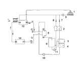
图1是热泵机组制冷剂切换的液体泵驱动溶液再生子系统流程图;Figure 1 is a flow chart of the liquid pump driven solution regeneration subsystem for refrigerant switching of the heat pump unit;
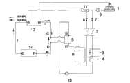
图2是热泵机组制冷剂切换的引射器引射溶液再生子系统流程图;Fig. 2 is a flow chart of the ejector injection solution regeneration subsystem for refrigerant switching of the heat pump unit;
图3(a)是热泵C、D端口带过冷器的I型单向节流转向开关管道连接结构示意图;Figure 3(a) is a schematic diagram of the pipe connection structure of the I-type one-way throttle steering switch with a subcooler at the ports C and D of the heat pump;
图3(b)是热泵C、D端口带过冷器的II型单向节流转向开关管道连接结构示意图;Figure 3(b) is a schematic diagram of the pipe connection structure of the type II one-way throttle steering switch with subcoolers at ports C and D of the heat pump;
图3(c)是热泵C、D端口带过冷器的III型节流装置管道连接结构示意图;Fig. 3(c) is a schematic diagram of the pipeline connection structure of the Type III throttling device with a subcooler at ports C and D of the heat pump;
图3(d)是热泵C、D端口不带过冷器的IV型单向节流转向开关管道连接结构示意图;Figure 3(d) is a schematic diagram of the pipe connection structure of the IV-type one-way throttle steering switch without a subcooler at the ports C and D of the heat pump;
图3(e)是热泵C、D端口不带过冷器的V型单向节流转向开关管道连接结构示意图;Figure 3(e) is a schematic diagram of the pipe connection structure of the V-shaped one-way throttle steering switch without a subcooler at the ports C and D of the heat pump;
图3(f)是热泵C、D端口不带过冷器的VI型节流装置管道连接结构示意图;Figure 3(f) is a schematic diagram of the pipeline connection structure of the VI-type throttling device without a subcooler at the ports C and D of the heat pump;
图4(a)再生热吸收器中G、H端口太阳能集热器与再生溶液管道直接接触的连接示意图;Figure 4(a) Schematic diagram of the direct contact between the G and H port solar collectors in the regenerative heat absorber and the regeneration solution pipeline;
图4(b)再生热吸收器中G、H端口太阳能集热器与再生溶液管道间接接触的连接示意图;Figure 4(b) Schematic diagram of the connection between the G and H port solar collectors in the regenerative heat absorber and the indirect contact with the regeneration solution pipeline;
图4(c)再生热吸收器中G、H端口废热热源与再生溶液管道直接接触的连接示意图;Figure 4(c) Schematic diagram of the direct contact between the waste heat source at ports G and H of the regenerative heat absorber and the regeneration solution pipeline;
图5溶液/空气预热器、第一再生器和第二再生器的组成结构及气流方向示意图;Figure 5 is a schematic diagram of the composition structure and airflow direction of the solution/air preheater, the first regenerator and the second regenerator;
图6是热泵机组换热流体切换的液体泵驱动溶液再生子系统流程图;Fig. 6 is a flow chart of the liquid pump driven solution regeneration subsystem for the heat exchange fluid switching of the heat pump unit;
图7是热泵机组换热流体切换的引射器引射溶液再生子系统流程图;Fig. 7 is a flow chart of the ejector injection solution regeneration subsystem for the heat exchange fluid switching of the heat pump unit;
图中:冷却塔1、溶液回热器2、溶液/空气预热器3、第一喷淋装置31、气/液换热器32、挡风淋液器33、第一再生器4、第一再生器填料41、第一再生储液器42、再生热吸收器5、第二再生器6、第二喷淋装置61、第二再生器填料62、第二再生储液器63、引风机64、第一调节阀7、第二调节阀8、第一液体泵9、第二液体泵10、第三液体泵11、过冷器12;、第一单向阀121、第二单向阀122、第三单向阀123、第四单向阀124、第一节流装置125、第二节流装置126、热泵机组室外换热器13、热泵机组室内换热器14、太阳能集热器15、废热热源15’、液液换热器16、第四液体泵17、第三调节阀18、第四调节阀19、第五调节阀20、第六调节阀21、第七调节阀22、第八调节阀23、第九调节阀24、第十调节阀25。In the figure:
具体实施方式Detailed ways
如图1所示,无霜型空气源热泵系统包括热泵机组、溶液吸热子系统和溶液再生子系统三部分;溶液再生子系统包括溶液回热器2、溶液/空气预热器3、第一再生器4、再生热吸收器5、第二再生器6、第一调节阀7、第二调节阀8、第二液体泵10和第三液体泵11,第一调节阀7出口与溶液回热器2的再生稀溶液进口、溶液/空气预热器3、第一再生器4、第二液体泵10、再生热吸收器5、第二再生器6进口依次连接,第二再生器6出口与第三液体泵11进口、溶液回热器2的再生浓溶液进口、第二调节阀8进口依次连接;溶液吸热子系统包括冷却塔1和第一液体泵9,第一液体泵9的出口分成两路,一路为再生稀溶液,与第一调节阀7进口相连,另一路为混合用稀溶液,与第二调节阀8出口相连;热泵机组包括A、B、C、D、E、F六个连接端口,A、B端口是热泵机组室外换热器13换热流体的连接端口,热泵机组A端口进口与第一液体泵9出口相连,热泵机组B端口出口与冷却塔1和第一液体泵9的进口依次相连;热泵机组C、D端口是热泵机组高压侧与低压侧制冷剂管道的连接端口,其与再生热吸收器5相连,热泵机组E、F端口是热泵机组室内换热器14换热流体的连接端口。As shown in Figure 1, the frost-free air source heat pump system includes three parts: the heat pump unit, the solution heat absorption subsystem and the solution regeneration subsystem; the solution regeneration subsystem includes the
如图2所示,另一种无霜型空气源热泵系统包括热泵机组、溶液吸热子系统和溶液再生子系统三部分;溶液再生子系统包括溶液回热器2、溶液/空气预热器3、第一再生器4、再生热吸收器5、第二再生器6、第一调节阀7、第二调节阀8、第二液体泵10,第一调节阀7出口与溶液回热器2的再生稀溶液进口、溶液/空气预热器3、第一再生器4、第二液体泵10、再生热吸收器5、第二再生器6进口依次连接,第二再生器6出口与溶液回热器2的再生浓溶液进口、第二调节阀8进口依次连接;溶液吸热子系统包括冷却塔1、第一液体泵9和引射器11’,第一液体泵9出口分成两路,一路为再生稀溶液,与第一调节阀7的进口相连,另一路为混合用稀溶液,与引射器11’的主干路相连,引射器11’的引射回路与与第二调节阀8出口相连;热泵机组包括A、B、C、D、E、F六个连接端口,热泵机组A、B端口是热泵机组室外换热器13换热流体的连接端口,热泵机组A端口进口与引射器11’出口相连,热泵机组B端口出口与冷却塔1、第一液体泵9和引射器11’的进口依次相连;热泵机组C、D端口是热泵机组高压侧与低压侧制冷剂管道的连接端口,与再生热吸收器5相连,热泵机组E、F端口是热泵机组室内换热器14换热流体的连接端口。As shown in Figure 2, another frost-free air source heat pump system includes three parts: heat pump unit, solution heat absorption subsystem and solution regeneration subsystem; the solution regeneration subsystem includes
如图3(a)所示,再生热吸收器5包括第一单向阀121、第二单向阀122、第三单向阀123、第四单向阀124、第一节流装置125、第二节流装置126、过冷器12;热泵机组制热工况下,制冷剂从第三单向阀123正向进入,第三单向阀123出口与过冷器12的一端口、第一节流装置125进口和第二单向阀122正向进口依次相连,过冷器12的制冷剂流动方向与再生热吸收器5中G、H端口的溶液流动方向相反;热泵机组制冷工况下,制冷剂从第一单向阀121正向进入,第一单向阀121出口与过冷器12另一端口、第二节流装置126进口和第四单向阀124正向进口依次相连。As shown in Figure 3 (a), the
如图3(b)所示,再生热吸收器5包括第一单向阀121、第二单向阀122、第三单向阀123、第四单向阀124、第一节流装置125、过冷器12;热泵机组制热工况下,制冷剂从第二单向阀122正向进入,第二单向阀122出口与过冷器12一端口、第一节流装置125进口和第四单向阀124正向进口依次相连,再生热吸收器5中G、H端口的溶液流动方向与过冷器12的制冷剂流动方向相反;热泵机组制冷工况下,制冷剂从第一单向阀121正向进入,第一单向阀121出口与过冷器12一端口、第一节流装置125进口和第三单向阀123正向进口依次相连。As shown in Figure 3 (b), the
如图3(c)所示,再生热吸收器5包括过冷器12和第一节流装置125;热泵机组为制冷循环,制冷剂从过冷器12一端口进入,过冷器12的另一端口与第一节流装置125进口相连,再生热吸收器5G、H端口的溶液流动方向与过冷器12的制冷剂流动方向相反。As shown in Figure 3 (c), the
如图5所示,溶液/空气预热器3包括第一喷淋装置31、气/液热交换器32和挡风淋液器33;第一再生器4包括第一再生器填料41和第一再生储液器42,挡风淋液器33是连接溶液/空气预热器3和第一再生器4的连接部件;溶液/空气预热器3、第一再生器4的同侧侧壁面与第二再生器6的一侧侧壁面共用;第二再生器6包括第二喷淋装置61、第二再生器填料62、第二再生储液器63和引风机64,第二喷淋装置61位于第二再生器填料62的上方,第二再生器填料62位于第二再生储液器63的上方,引风机64位于第二再生器填料62和第二再生储液器63之间,且靠近第二再生器6与第一再生器4的公共壁面处。As shown in Figure 5, the solution/
如图6所示,无霜型空气源热泵系统包括热泵机组、溶液吸热子系统和溶液再生子系统三部分;溶液再生子系统和溶液吸热子系统与图1同,热泵机组只有制冷循环,热泵机组A端口进口与第五调节阀20和第四调节阀19分别相连,热泵机组B端口出口与第六调节阀21和第三调节阀18分别相连;热泵机组C、D端口是热泵机组高压侧与低压侧制冷剂管道的连接端口,其与再生热吸收器5相连,热泵机组E、F端口是热泵机组室内换热器14换热流体的连接端口。热泵机组E端口进口与第七调节阀22和第九调节阀24分别相连,热泵机组F端口出口与第八调节阀23和第十调节阀25分别相连。夏季工况下,第三调节阀18、第四调节阀19、第九调节阀24、第十调节阀25均关闭,第五调节阀20、第六调节阀21、第七调节阀22、第八调节阀23全部打开。冬季工况下,第三调节阀18、第四调节阀19、第九调节阀24、第十调节阀25均打开,第五调节阀20、第六调节阀21、第七调节阀22、第八调节阀23全部关闭。As shown in Figure 6, the frost-free air source heat pump system includes three parts: the heat pump unit, the solution heat absorption subsystem and the solution regeneration subsystem; , the inlet of port A of the heat pump unit is connected to the fifth regulating
如图7所示,无霜型空气源热泵系统包括热泵机组、溶液吸热子系统和溶液再生子系统三部分;溶液再生子系统和溶液吸热子系统与图2同,热泵机组只有制冷循环,换热流体具体连接形式与图6相同。As shown in Figure 7, the frost-free air source heat pump system includes three parts: the heat pump unit, the solution heat absorption subsystem and the solution regeneration subsystem; the solution regeneration subsystem and the solution heat absorption subsystem are the same as in Figure 2, and the heat pump unit only has the refrigeration cycle , the specific connection form of the heat exchange fluid is the same as that in Fig. 6 .
实施方案可以分两类,第一类热泵子系统为制冷剂切换,包括制冷循环和制热循环两种形式,而热泵机组室内外换热器换热流体不作切换。具体有如下几种实施方式:The implementation schemes can be divided into two categories. The first type of heat pump subsystem is refrigerant switching, including two forms of refrigeration cycle and heating cycle, and the heat exchange fluid of the indoor and outdoor heat exchangers of the heat pump unit does not switch. Specifically, there are several implementation methods as follows:
第1-1种实施方案,即再生热源为热泵子系统的过冷器12,再生后流体由第三液体泵11驱动。Embodiment 1-1, that is, the regeneration heat source is the
具体实施过程为:溶液吸热子系统中溶液吸热循环为,浓度较高的溶液进入热泵机组室外换热器13,与室外换热器13发生热量交换后,溶液温度降低而浓度不变,进入冷却塔吸收环境空气的显热和部分潜热后,溶液温度升高浓度降低,从第一液体泵9流出的稀溶液,一部分经第一调节阀7进口进入再生子系统,再生后的浓溶液从第二调节阀8出口流出,与另一部分稀溶液混合后再次进入热泵机组室外换热器13中。The specific implementation process is as follows: the heat absorption cycle of the solution in the solution heat absorption subsystem is that the solution with a higher concentration enters the
溶液再生子系统中溶液再生循环为,需要再生的稀溶液经第一调节阀7,依次流入溶液回热器2、溶液/空气预热器3、第一再生器4,在第一种再生热吸收器5(如图3(a))或第二种再生热吸收器5(如图3(b))中吸收过冷器12的热量后,进入第二再生器6中,溶液被空气浓缩冷却后依次进入第三液体泵11和溶液回热器2的浓溶液进口,最后从第二调节阀8中流出。The solution regeneration cycle in the solution regeneration subsystem is that the dilute solution to be regenerated passes through the
溶液再生子系统中空气的流程为,室外环境空气先进入第一再生填料区41,与从挡风淋液器33下来的溶液进行换热,经引风机64进入第二再生填料区63中,与流入第二再生器6的高温稀溶液热质交换后,变成湿热空气,进入气/液换热器32中,与气/液换热器32外侧再生溶液换热后,变成温度略高于0℃的湿冷空气流出。The flow of air in the solution regeneration subsystem is that the outdoor ambient air first enters the first regeneration filling area 41, exchanges heat with the solution coming down from the windshield shower 33, and enters the second regeneration filling area 63 through the induced draft fan 64. After exchanging heat and mass with the high-temperature dilute solution flowing into the
第1-2种实施方案,即再生热源为热泵子系统的过冷器12,再生后流体由引射器11’驱动。In the first and second implementations, the regenerative heat source is the
具体实施过程为:溶液吸热子系统中溶液吸热循环为,浓度较高的溶液进入热泵机组室外换热器13,与室外换热器13发生热量交换后,溶液温度降低而浓度不变,进入冷却塔吸收环境空气的显热和部分潜热后,溶液温度升高浓度降低,从第一液体泵9流出的稀溶液,一部分经第一调节阀7进口进入再生子系统,再生后的浓溶液从第二调节阀8出口流出,通过引射器11’的引射回路与另一部分稀溶液混合后再次进入室外换热器13中。The specific implementation process is as follows: the heat absorption cycle of the solution in the solution heat absorption subsystem is that the solution with a higher concentration enters the
溶液再生子系统中溶液再生循环为,需要再生的溶液经第一调节阀7,依次流入溶液回热器2、溶液/空气预热器3、第一再生器4,在第一种再生热吸收器5(如图3(a))或第二种再生热吸收器5(如图3(b))中吸收过冷器12的热量后,进入第二再生器6中,溶液被空气浓缩冷却后经溶液回热器2的浓溶液进口、第二调节阀8进口,由引射器11’的引射回路流出。The solution regeneration cycle in the solution regeneration subsystem is that the solution to be regenerated passes through the
溶液再生子系统中空气的流程与实施方案一同。The flow of air in the solution regeneration subsystem is with the implementation.
第1-3、第1-4、第1-5、第1-6种实施方案,再生热源为太阳能集热器15,再生后流体由第三液体泵11驱动。In the 1-3, 1-4, 1-5, and 1-6 implementations, the regeneration heat source is a
第1-3实施方案中再生热吸收器包括第一单向阀121、第二单向阀122、第三单向阀123、第四单向阀124、第一节流装置125、第二节流装置126和太阳能集热器15(如图3(c)和图4(a));热泵机组制热工况下,制冷剂从第三单向阀123正向进入,第三单向阀123出口与第一节流装置125进口、第二单向阀122正向进口依次相连,再生热吸收器G、H端口的溶液与太阳能集热器15直接接触;热泵机组制冷工况下,制冷剂从第一单向阀121正向进入,第一单向阀121出口与第二节流装置126进口和第四单向阀124正向进口依次相连。In the first to third embodiments, the regenerative heat absorber includes a first one-
第1-4实施方案中再生热吸收器包括第一单向阀121、第二单向阀122、第三单向阀123、第四单向阀124、第一节流装置125和太阳能集热器15(如图3(d)和图4(a));热泵机组制热工况下,制冷剂从第二单向阀122正向进入,第二单向阀122出口与第一节流装置125进口、第四单向阀124正向进口依次相连,再生热吸收器G、H端口的溶液与太阳能集热器15直接接触;热泵机组制冷工况下,制冷剂从第一单向阀121正向进入,第一单向阀121出口与第一节流装置125进口和第三单向阀123正向进口依次相连。In the 1st-4th embodiment, the regenerative heat absorber includes a first one-
第1-5实施方案中再生热吸收器包括第一单向阀121、第二单向阀122、第三单向阀123、第四单向阀124、第一节流装置125、第二节流装置126、太阳能集热器15、液液换热器16、第四液体泵17(如图3(c)和4(b));制冷剂流程与第三实施方案同。In the first to fifth embodiments, the regenerative heat absorber includes a first one-
第1-6实施方案中再生热吸收器包括第一单向阀121、第二单向阀122、第三单向阀123、第四单向阀124、第一节流装置125、太阳能集热器15、液液换热器16、第四液体泵17(如图3(d)和4(b));制冷剂流程与第四实施方案同。In the 1st-6th embodiment, the regenerative heat absorber includes a first one-
第1-3、第1-4、第1-5、第1-6种实施方案的其余循环均与第1-1种实施方案同。All the other cycles of the 1-3, 1-4, 1-5, 1-6 implementations are the same as the 1-1 implementations.
类似实施方案有再生热源为太阳能集热器15,再生后流体由引射器11’驱动;或再生热源为废热热源15’(如图3(c)和4(c))或(如图3(d)和4(c)),再生后流体由引射器11’驱动,再生吸热器5的组成类似第1-3、第1-4、第1-5、第1-6方案,而其余循环与第1-2实施方案同,在此不赘述。Similar embodiments have the regenerative heat source as the
实施方案的第二类热泵子系统为换热流体切换,热泵子系统只有制冷循环,制冷剂不切换。具体实施方式如图6或如图7,再生溶液的驱动动力为第三液体泵11或引射器11’,再生热源可以是过冷器12(如图3(c)),也可以太阳能集热器15或废热热源15’,热泵机组C、D端口连接形式为图3(f)。The second type of heat pump subsystem in the embodiment is switching of the heat exchange fluid, and the heat pump subsystem only has a refrigeration cycle, and the refrigerant is not switched. 6 or 7, the driving power of the regeneration solution is the third
Claims (8)
Translated fromChinesePriority Applications (1)
| Application Number | Priority Date | Filing Date | Title |
|---|---|---|---|
| CN2009100980085ACN101634501B (en) | 2009-04-23 | 2009-04-23 | Frost-free type air source heat pump system |
Applications Claiming Priority (1)
| Application Number | Priority Date | Filing Date | Title |
|---|---|---|---|
| CN2009100980085ACN101634501B (en) | 2009-04-23 | 2009-04-23 | Frost-free type air source heat pump system |
Publications (2)
| Publication Number | Publication Date |
|---|---|
| CN101634501Atrue CN101634501A (en) | 2010-01-27 |
| CN101634501B CN101634501B (en) | 2011-05-18 |
Family
ID=41593766
Family Applications (1)
| Application Number | Title | Priority Date | Filing Date |
|---|---|---|---|
| CN2009100980085AExpired - Fee RelatedCN101634501B (en) | 2009-04-23 | 2009-04-23 | Frost-free type air source heat pump system |
Country Status (1)
| Country | Link |
|---|---|
| CN (1) | CN101634501B (en) |
Cited By (7)
| Publication number | Priority date | Publication date | Assignee | Title |
|---|---|---|---|---|
| CN101776353A (en)* | 2010-02-10 | 2010-07-14 | 东南大学 | Cooling tower-based solution type cold and hot water unit |
| CN102155815A (en)* | 2011-03-30 | 2011-08-17 | 浙江大学 | Steam jet refrigeration system based on double-fluid |
| CN103216981A (en)* | 2013-04-28 | 2013-07-24 | 宁波沃弗圣龙环境技术有限公司 | Frostless air handling unit and proportion-integration-differential control method thereof |
| CN103486680A (en)* | 2013-09-23 | 2014-01-01 | 广东西屋康达空调有限公司 | Energy-saving frostless air source air conditioning heat pump system |
| CN106765451A (en)* | 2016-12-01 | 2017-05-31 | 南昌大学 | A kind of frost-free type solution heat pump device |
| CN108120190A (en)* | 2017-11-10 | 2018-06-05 | 山东奇威特太阳能科技有限公司 | A kind of method that absorption installation heat exchanger surface delays frosting |
| CN110319617A (en)* | 2019-07-01 | 2019-10-11 | 上海理工大学 | Gas-fired heat pump device based on heat source tower |
- 2009
- 2009-04-23CNCN2009100980085Apatent/CN101634501B/ennot_activeExpired - Fee Related
Cited By (9)
| Publication number | Priority date | Publication date | Assignee | Title |
|---|---|---|---|---|
| CN101776353A (en)* | 2010-02-10 | 2010-07-14 | 东南大学 | Cooling tower-based solution type cold and hot water unit |
| CN102155815A (en)* | 2011-03-30 | 2011-08-17 | 浙江大学 | Steam jet refrigeration system based on double-fluid |
| CN103216981A (en)* | 2013-04-28 | 2013-07-24 | 宁波沃弗圣龙环境技术有限公司 | Frostless air handling unit and proportion-integration-differential control method thereof |
| CN103486680A (en)* | 2013-09-23 | 2014-01-01 | 广东西屋康达空调有限公司 | Energy-saving frostless air source air conditioning heat pump system |
| CN103486680B (en)* | 2013-09-23 | 2016-04-20 | 广东西屋康达空调有限公司 | A kind of energy-saving Frostless air-source air conditioner heat pump system |
| CN106765451A (en)* | 2016-12-01 | 2017-05-31 | 南昌大学 | A kind of frost-free type solution heat pump device |
| CN108120190A (en)* | 2017-11-10 | 2018-06-05 | 山东奇威特太阳能科技有限公司 | A kind of method that absorption installation heat exchanger surface delays frosting |
| CN110319617A (en)* | 2019-07-01 | 2019-10-11 | 上海理工大学 | Gas-fired heat pump device based on heat source tower |
| CN110319617B (en)* | 2019-07-01 | 2021-04-30 | 上海理工大学 | Gas heat pump device based on heat source tower |
Also Published As
| Publication number | Publication date |
|---|---|
| CN101634501B (en) | 2011-05-18 |
Similar Documents
| Publication | Publication Date | Title |
|---|---|---|
| CN101701737B (en) | Heat-pump-driven solution dehumidifying air-conditioning device | |
| CN103983042B (en) | The indoor cold-hot integrated system of a kind of solar energy | |
| CN101634501B (en) | Frost-free type air source heat pump system | |
| CN102022793B (en) | Efficient heat pump type heat source tower solution regeneration device and method based on latent heat recovery | |
| CN101571330B (en) | A frost-free multifunctional solar-assisted heat pump system | |
| CN201764752U (en) | Combined heating and cooling system coupled with solar air conditioning and ground source heat pump | |
| CN105222404B (en) | It is a kind of to utilize solar energy-air energy heat pump system | |
| CN101963412A (en) | Solar energy and electric energy combined heat pump system and cooling and heating method | |
| CN202083061U (en) | A solar absorption air conditioner | |
| CN103644612A (en) | Heat source tower heat pump air-conditioning system capable of using cool storage device to assist heating | |
| CN201819480U (en) | High-efficiency energy-saving heat pump device | |
| CN201311130Y (en) | Evaporative condenser heat pump central air conditioner | |
| CN102901374A (en) | Heat source tower device with pre-setting function | |
| CN103591663B (en) | Two high-efficiency heat pump air-conditioning system of a kind of summer in winter based on energy tower and method | |
| CN205783976U (en) | The refrigeration system that a kind of solar energy absorption type refrigeration is compound with absorption type refrigerating | |
| CN104567104A (en) | Solution heat pump system based on freezing regeneration and heat recovery thereof | |
| CN201875830U (en) | Latent heat recycling based efficient heat pump-type device for regenerating solutions in heat-source tower | |
| CN107631642B (en) | An air conditioning system including a heat source tower that uses phase change to exchange heat with air | |
| CN204555427U (en) | A kind of novel air-cooled heat pump utilizing solar energy | |
| CN201318799Y (en) | Air source heat water heater | |
| CN101504224B (en) | Solar energy and engine exhaust heat dual-power refrigeration air conditioner for vehicle | |
| CN105716324A (en) | Double-heat-source efficient air conditioner system based on compression-injection combination and application | |
| CN203100033U (en) | Two-stage reverse osmosis regeneration heat source tower heat pump system | |
| CN111595066B (en) | A heating regeneration frost-free heat pump integrated machine | |
| CN206504423U (en) | Heat source tower heat pump using soil to realize comprehensive utilization of solar energy and inter-seasonal energy storage |
Legal Events
| Date | Code | Title | Description |
|---|---|---|---|
| C06 | Publication | ||
| PB01 | Publication | ||
| C10 | Entry into substantive examination | ||
| SE01 | Entry into force of request for substantive examination | ||
| C14 | Grant of patent or utility model | ||
| GR01 | Patent grant | ||
| C17 | Cessation of patent right | ||
| CF01 | Termination of patent right due to non-payment of annual fee | Granted publication date:20110518 Termination date:20140423 |