CN101632947B - Microstructure arrangement for the bubble-free filling with a liquid of at least one system for draining off liquids - Google Patents
Microstructure arrangement for the bubble-free filling with a liquid of at least one system for draining off liquidsDownload PDFInfo
- Publication number
- CN101632947B CN101632947BCN2009101603255ACN200910160325ACN101632947BCN 101632947 BCN101632947 BCN 101632947BCN 2009101603255 ACN2009101603255 ACN 2009101603255ACN 200910160325 ACN200910160325 ACN 200910160325ACN 101632947 BCN101632947 BCN 101632947B
- Authority
- CN
- China
- Prior art keywords
- transition region
- liquid
- outlet
- inlet
- micro
- Prior art date
- Legal status (The legal status is an assumption and is not a legal conclusion. Google has not performed a legal analysis and makes no representation as to the accuracy of the status listed.)
- Expired - Lifetime
Links
- 239000007788liquidSubstances0.000titleclaimsabstractdescription134
- 230000007704transitionEffects0.000claimsabstractdescription165
- 238000009736wettingMethods0.000claimsabstractdescription11
- 230000005499meniscusEffects0.000claimsabstractdescription9
- 238000011176poolingMethods0.000claimsdescription16
- 230000008676importEffects0.000claims2
- 238000012797qualificationMethods0.000claims2
- 239000012530fluidSubstances0.000description11
- 238000007599dischargingMethods0.000description4
- 230000000694effectsEffects0.000description2
- 238000000034methodMethods0.000description2
- 239000011324beadSubstances0.000description1
- 230000015572biosynthetic processEffects0.000description1
- 230000004858capillary barrierEffects0.000description1
- 238000011161developmentMethods0.000description1
- 230000018109developmental processEffects0.000description1
- 238000007373indentationMethods0.000description1
- 238000005192partitionMethods0.000description1
- 239000010902strawSubstances0.000description1
Images


Classifications
- B—PERFORMING OPERATIONS; TRANSPORTING
- B01—PHYSICAL OR CHEMICAL PROCESSES OR APPARATUS IN GENERAL
- B01L—CHEMICAL OR PHYSICAL LABORATORY APPARATUS FOR GENERAL USE
- B01L3/00—Containers or dishes for laboratory use, e.g. laboratory glassware; Droppers
- B01L3/50—Containers for the purpose of retaining a material to be analysed, e.g. test tubes
- B01L3/502—Containers for the purpose of retaining a material to be analysed, e.g. test tubes with fluid transport, e.g. in multi-compartment structures
- B01L3/5027—Containers for the purpose of retaining a material to be analysed, e.g. test tubes with fluid transport, e.g. in multi-compartment structures by integrated microfluidic structures, i.e. dimensions of channels and chambers are such that surface tension forces are important, e.g. lab-on-a-chip
- B01L3/502723—Containers for the purpose of retaining a material to be analysed, e.g. test tubes with fluid transport, e.g. in multi-compartment structures by integrated microfluidic structures, i.e. dimensions of channels and chambers are such that surface tension forces are important, e.g. lab-on-a-chip characterised by venting arrangements
- B—PERFORMING OPERATIONS; TRANSPORTING
- B01—PHYSICAL OR CHEMICAL PROCESSES OR APPARATUS IN GENERAL
- B01L—CHEMICAL OR PHYSICAL LABORATORY APPARATUS FOR GENERAL USE
- B01L2200/00—Solutions for specific problems relating to chemical or physical laboratory apparatus
- B01L2200/06—Fluid handling related problems
- B01L2200/0621—Control of the sequence of chambers filled or emptied
- B—PERFORMING OPERATIONS; TRANSPORTING
- B01—PHYSICAL OR CHEMICAL PROCESSES OR APPARATUS IN GENERAL
- B01L—CHEMICAL OR PHYSICAL LABORATORY APPARATUS FOR GENERAL USE
- B01L2200/00—Solutions for specific problems relating to chemical or physical laboratory apparatus
- B01L2200/06—Fluid handling related problems
- B01L2200/0684—Venting, avoiding backpressure, avoid gas bubbles
- B—PERFORMING OPERATIONS; TRANSPORTING
- B01—PHYSICAL OR CHEMICAL PROCESSES OR APPARATUS IN GENERAL
- B01L—CHEMICAL OR PHYSICAL LABORATORY APPARATUS FOR GENERAL USE
- B01L2300/00—Additional constructional details
- B01L2300/08—Geometry, shape and general structure
- B01L2300/0861—Configuration of multiple channels and/or chambers in a single devices
- B01L2300/0864—Configuration of multiple channels and/or chambers in a single devices comprising only one inlet and multiple receiving wells, e.g. for separation, splitting
- B—PERFORMING OPERATIONS; TRANSPORTING
- B01—PHYSICAL OR CHEMICAL PROCESSES OR APPARATUS IN GENERAL
- B01L—CHEMICAL OR PHYSICAL LABORATORY APPARATUS FOR GENERAL USE
- B01L2400/00—Moving or stopping fluids
- B01L2400/06—Valves, specific forms thereof
- B01L2400/0688—Valves, specific forms thereof surface tension valves, capillary stop, capillary break
- B—PERFORMING OPERATIONS; TRANSPORTING
- B01—PHYSICAL OR CHEMICAL PROCESSES OR APPARATUS IN GENERAL
- B01L—CHEMICAL OR PHYSICAL LABORATORY APPARATUS FOR GENERAL USE
- B01L3/00—Containers or dishes for laboratory use, e.g. laboratory glassware; Droppers
- B01L3/50—Containers for the purpose of retaining a material to be analysed, e.g. test tubes
- B01L3/502—Containers for the purpose of retaining a material to be analysed, e.g. test tubes with fluid transport, e.g. in multi-compartment structures
- B01L3/5027—Containers for the purpose of retaining a material to be analysed, e.g. test tubes with fluid transport, e.g. in multi-compartment structures by integrated microfluidic structures, i.e. dimensions of channels and chambers are such that surface tension forces are important, e.g. lab-on-a-chip
- B01L3/502746—Containers for the purpose of retaining a material to be analysed, e.g. test tubes with fluid transport, e.g. in multi-compartment structures by integrated microfluidic structures, i.e. dimensions of channels and chambers are such that surface tension forces are important, e.g. lab-on-a-chip characterised by the means for controlling flow resistance, e.g. flow controllers, baffles
- Y—GENERAL TAGGING OF NEW TECHNOLOGICAL DEVELOPMENTS; GENERAL TAGGING OF CROSS-SECTIONAL TECHNOLOGIES SPANNING OVER SEVERAL SECTIONS OF THE IPC; TECHNICAL SUBJECTS COVERED BY FORMER USPC CROSS-REFERENCE ART COLLECTIONS [XRACs] AND DIGESTS
- Y10—TECHNICAL SUBJECTS COVERED BY FORMER USPC
- Y10T—TECHNICAL SUBJECTS COVERED BY FORMER US CLASSIFICATION
- Y10T436/00—Chemistry: analytical and immunological testing
- Y10T436/11—Automated chemical analysis
- Y10T436/110833—Utilizing a moving indicator strip or tape
- Y—GENERAL TAGGING OF NEW TECHNOLOGICAL DEVELOPMENTS; GENERAL TAGGING OF CROSS-SECTIONAL TECHNOLOGIES SPANNING OVER SEVERAL SECTIONS OF THE IPC; TECHNICAL SUBJECTS COVERED BY FORMER USPC CROSS-REFERENCE ART COLLECTIONS [XRACs] AND DIGESTS
- Y10—TECHNICAL SUBJECTS COVERED BY FORMER USPC
- Y10T—TECHNICAL SUBJECTS COVERED BY FORMER US CLASSIFICATION
- Y10T436/00—Chemistry: analytical and immunological testing
- Y10T436/11—Automated chemical analysis
- Y10T436/111666—Utilizing a centrifuge or compartmented rotor
Landscapes
- Chemical & Material Sciences (AREA)
- Health & Medical Sciences (AREA)
- Dispersion Chemistry (AREA)
- Analytical Chemistry (AREA)
- General Health & Medical Sciences (AREA)
- Hematology (AREA)
- Clinical Laboratory Science (AREA)
- Chemical Kinetics & Catalysis (AREA)
- Physical Or Chemical Processes And Apparatus (AREA)
- Micromachines (AREA)
- Feeding, Discharge, Calcimining, Fusing, And Gas-Generation Devices (AREA)
- Coating Apparatus (AREA)
Abstract
Translated fromChinese
Description
Translated fromChinese本申请是申请号为200410094216.5的原申请的分案申请,原申请的申请日为2004年12月20日、发明名称为“用于无气泡地填充至少一个用于排出液体的系统的微结构装置、具有这种装置的器具和填充方法”。 This application is a divisional application of the original application with the application number 200410094216.5, the filing date of the original application is December 20, 2004, and the title of the invention is "Microstructure device for filling at least one system for discharging liquid without bubbles , a device having such a device and a filling method". the
技术领域technical field
本发明涉及一种用于以一种液体无气泡地填充至少一个用于排出液体的系统(液体输出系统)的装置。 The invention relates to a device for bubble-free filling of at least one system for discharging a liquid (liquid delivery system) with a liquid. the
背景技术Background technique
在输送液体时由于在微结构系统中的毛细力,在输送路程中总是有带气泡的问题。这可能妨碍或甚至阻止所希望的液体输送。气泡经常在液体流转向时形成,例如在一个通道绕90°改变其方向时。在角区域中存在的棱边可以导致,在所述角区域完全被液体润湿之前,所述角区域没有完全被液体润湿并且液体已经进入到绕90°拐弯的通道段中(液体输出系统)。然后液体流在一个在角区域中形成的气泡的旁边流过,并进入到90°折弯的通道段中。但位于所述角区域中的气泡可以进一步从所述角区域中脱离,并且作为塞子位于绕90°折弯的通道段之前,也就是液体输出系统之前。由此可以阻止或至少阻碍进一步的液体输送。 When conveying liquids, there is always the problem of air bubbles in the conveying path due to the capillary forces in the microstructural system. This may hinder or even prevent desired fluid delivery. Bubbles are often formed when liquid flow turns, for example when a channel changes its direction around 90°. The presence of edges in the corner area can lead to the fact that the corner area is not completely wetted by the liquid and the liquid has already entered the channel section that turns around 90° before the corner area is completely wetted by the liquid (liquid delivery system ). The liquid flow then flows past an air bubble formed in the corner region and enters the 90° bent channel section. However, air bubbles located in the corner region can further escape from the corner region and be located as a plug in front of the channel section bent at 90°, ie in front of the fluid outlet system. Further liquid delivery can thereby be prevented or at least hindered. the
如果应该通过一个分支点把液体引到不同的液体输出系统中,可能出现类似的效果。在这里也不一定保证,在所有的液体输出系统润湿并且以液体填充之前,该分支点以液体填充并且在分支点上没有气泡。 A similar effect can occur if the liquid is to be led via a branch point into different liquid output systems. Here, too, it is not necessarily guaranteed that the branch point is filled with liquid and that there are no air bubbles at the branch point before all the liquid outlet systems are wetted and filled with liquid. the
从公开号为EP 1 201 304 A2的专利文献中已知一种用于检验液体的微结构平台,在该平台中,通过毛细力用液体填充不同的空腔。因此例如从此专利文献的图4中已知一个腔室130,它通过一个输入通道450填充。该腔室具有一个比较大的深度并且输入通道直接通入腔室盖板的下方,其中流入区域有一个小的横截面积。因此在流入区域中存在一个从输入通道的小横截面面到腔室的大横截面积的突然的过渡,它如一个 毛细阻塞那样起作用,在该过渡处中断液体输送。但是为了能够不中断液体输送并且通过输入通道实现完全地填充腔室,设置一个缺口440,它在腔室的侧壁上从输入通道的流入区域延伸至腔室的底部。在该缺口中存在一个增高的毛细力,这使得,通过输入通道引入的液体沿着缺口吸到腔室的底部。该缺口这样把液体引入到腔室的底部,并且然后将液体从腔室的底部提升到腔室中。在腔室完全被液体填满之前,腔室的出口朝入口结构410那边被润湿,并且液体从腔室130流出。但然后空气被包括在腔室130中,这是不期望的。 A microstructure platform for testing liquids is known from the patent publication EP 1 201 304 A2, in which various cavities are filled with liquid by capillary forces. A chamber 130 is thus known, for example, from FIG. 4 of this patent document, which is filled via an inlet channel 450 . The chamber has a comparatively large depth and the feed channel opens directly below the chamber cover, the inflow region having a small cross-sectional area. Therefore, there is a sudden transition from the small cross-sectional area of the inlet channel to the large cross-sectional area of the chamber in the inflow region, which acts like a capillary blockage, interrupting the liquid transport at this transition. However, in order to be able to completely fill the chamber with the feed channel without interrupting the liquid supply, a recess 440 is provided in the side wall of the chamber, which extends from the inflow region of the feed channel to the bottom of the chamber. There is an increased capillary force in this opening, which causes the liquid introduced through the feed channel to be sucked along the opening to the bottom of the chamber. The notch thus introduces the liquid into the bottom of the chamber and then lifts the liquid from the bottom of the chamber into the chamber. Before the chamber is completely filled with liquid, the outlet of the chamber is wetted towards the inlet structure 410 and liquid flows out of the chamber 130 . But then air is included in the chamber 130, which is not desired. the
从专利文献WO 99/46045图5和7中已知一种类似的缺口,在那里被称为导入槽52,它实现如在EP 1 201 304 A2中的缺口的同样的目的。 Known a kind of similar breach from patent document WO 99/46045 Fig. 5 and 7, be referred to as lead-in groove 52 there, it realizes the same purpose as the breach in EP 1 201 304 A2. the
此外,在专利文献EP 1 201 304 A2中描述了级联和蝶形结构,它们在一个以均匀速度流动的液体层中实现液体流的均匀扩散(或相反一个宽的液体流的相同形状的汇合)。但级联和蝶形结构仅仅保证有气泡地填充一个邻接的腔室。而在腔室中本身具有在边缘上的延缓结构,它们防止边缘流赶在前面并因此防止包含气泡。 Furthermore, cascade and butterfly structures are described in patent document EP 1 201 304 A2, which achieve a uniform spread of liquid streams in a liquid layer flowing at a uniform velocity (or conversely the same shaped confluence of a wide liquid stream ). However, the cascade and butterfly structures only ensure that an adjoining chamber is filled with air bubbles. On the other hand, there are delay structures at the edges in the chamber itself, which prevent the edge flow from being overtaken and thus prevent the inclusion of air bubbles. the
发明内容Contents of the invention
本发明的目的在于,建议一种装置,它保证无气泡地填充一个或多个所述液体输出系统。 The object of the present invention is to propose a device which ensures bubble-free filling of one or more of the liquid delivery systems. the
该目的通过按本发明的装置达到。本发明有利扩展构造在下面描述。 This object is achieved by the device according to the invention. Advantageous developments of the invention are described below. the
按本发明的用于以一种液体无气泡地填充至少一个用于排出液体的系统的微结构装置,包括以下特征:该装置具有一个用于将该装置与一个用于输入液体的系统连接的入口;该装置具有至少一个用于将该装置与所述至少一个排出液体的系统连接的出口;该装置具有一个过渡区,通过该过渡区,液体可从入口输送到所述至少一个出口;在过渡区的始端设置至少一个第一微结构元件,用于产生一个具有增高的毛细力的位置,以便达到完全地润湿限定所述具有增高的毛细力的位置的表面,并且以便从过渡区的始端到过渡区的末端产生一个由于毛细力吸引的液体弯月面,以及,在入口和过渡区之间设置一个用于收集通过入口输入的液体的汇集区,其中,汇集区高于过渡区,以及,汇集区通过所述具有增高的毛细力的位置和另外通过一个毛细阻塞与过渡区隔开,该毛细阻塞设计为在汇集区和过渡区之间的凸缘,其中,过渡区向着出口的方向锥形地收缩。According to the microstructural device according to the invention for filling at least one system for discharging liquid with a liquid without bubbles, the device has the following features: the device has a device for connecting the device to a system for feeding liquid Inlet; the device has at least one outlet for connecting the device to the at least one liquid discharge system; the device has a transition zone through which liquid can be transported from the inlet to the at least one outlet; in The beginning of the transition zone is provided with at least one first microstructured element for producing a site of increased capillary force in order to achieve complete wetting of the surface defining said site of increased capillary force and to facilitate the transition from the transition zone The beginning to the end of the transition zone creates a meniscus of liquid due to capillary attraction, and, between the inlet and the transition zone, a collection zone for collecting the liquid input through the inlet is provided, wherein the collection zone is higher than the transition zone, And, the collection area is separated from the transition area by the location with increased capillary force and additionally by a capillary stopper, which is designed as a flange between the collection area and the transition area, wherein the transition area faces towards the outlet. The direction shrinks conically.
按本发明的用于以一种液体无气泡地填充至少一个用于排出液体的系统的微结构装置,包括以下特征:该装置具有一个用于将该装置与一个用于输入液体的系统连接的入口;该装置具有至少一个用于将该装置与所述至少一个排出液体的系统连接的出口;该装置具有一个过渡区,通过该过渡区,液体可从入口输送到所述至少一个出口;在过渡区的始端设置至少一个第一微结构元件,用于产生一个具有增高的毛细力的位置,以便达到完全地润湿限定所述具有增高的毛细力的位置的表面,并且以便从过渡区的始端到过渡区的末端产生一个由于毛细力吸引的液体弯月面,以及,在入口和过渡区之间设置一个用于收集通过入口输入的液体的汇集区,其中,过渡区高于汇集区,以及,汇集区通过所述具有增高的毛细力的位置和另外通过一个毛细阻塞与过渡区隔开,该毛细阻塞设计为在汇集区和过渡区之间的凸缘,其中,过渡区向着出口的方向锥形地收缩。 According to the microstructural device according to the invention for filling at least one system for discharging liquid with a liquid without bubbles, the device has the following features: the device has a device for connecting the device to a system for feeding liquid Inlet; the device has at least one outlet for connecting the device to the at least one liquid discharge system; the device has a transition zone through which liquid can be transported from the inlet to the at least one outlet; in The beginning of the transition zone is provided with at least one first microstructured element for producing a site of increased capillary force in order to achieve complete wetting of the surface defining said site of increased capillary force and to facilitate the transition from the transition zone The beginning to the end of the transition zone creates a meniscus of liquid due to capillary attraction, and, between the inlet and the transition zone, a collection zone for collecting the liquid input through the inlet is provided, wherein the transition zone is higher than the collection zone, And, the collection area is separated from the transition area by the location with increased capillary force and additionally by a capillary stopper, which is designed as a flange between the collection area and the transition area, wherein the transition area faces towards the outlet. The direction shrinks conically. the
因此,一种按本发明用于以液体无气泡地填充至少一个液体输出系统的微结构装置具有一个用于将该装置与一个用于输入液体的系统(液体输入系统)连接的入口。此外,该装置具有至少一个用于将该装置与至少一个液体输出系统连接的出口,并且该装置包括一个过渡区,通过该过渡区液体可从入口输送到所述至少一个出口。在过渡区的始端设置至少一个第一微结构元件,用于产生一个具有增高毛细力的位置,以便达到完全地润湿限定所述具有增高的毛细力的位置的表面,尤其是侧壁、盖板和/或底部。 Thus, a microstructured device according to the invention for filling at least one liquid delivery system with liquid without bubbles has an inlet for connecting the device to a system for feeding a liquid (liquid supply system). Furthermore, the device has at least one outlet for connecting the device to at least one liquid delivery system, and the device comprises a transition region through which liquid can be conveyed from the inlet to the at least one outlet. At least one first microstructured element is arranged at the beginning of the transition zone for producing a position of increased capillary force in order to achieve complete wetting of the surfaces delimiting said position of increased capillary force, in particular side walls, covers plate and/or bottom. the
在过渡区始端的完全的润湿使得,在过渡区的始端不能形成气泡。然后由于作用的毛细力,一个液体弯月面从过渡区的始端吸引至过渡区的末端也就是该装置的出口。在此排除了包含气泡。由此可以通过过渡区不形成气泡地输送液体,并且保证无气泡地填充与出口邻接的液体输出系统。在用液体填充前包含在过渡区内的空气通过液体向出口方向向前推进而排挤到液体输出系统中。 Complete wetting at the beginning of the transition zone is such that bubbles cannot form at the beginning of the transition zone. A meniscus of liquid is then attracted from the beginning of the transition zone to the end of the transition zone, which is the outlet of the device, due to capillary forces acting on it. The inclusion of air bubbles is excluded here. As a result, the liquid can be transported through the transition zone without forming air bubbles, and a bubble-free filling of the liquid delivery system adjacent to the outlet is ensured. The air contained in the transition zone prior to filling with liquid is displaced into the liquid delivery system by the liquid advancing in the direction of the outlet. the
有利地,从始端到末端的过渡区具有一个无突然的过渡或角或类似 物的相同形状的横截面。Advantageously, the transition zone from start to end has a cross-section of the same shape without abrupt transitions or corners or the like.
在按本发明的装置中,在入口和过渡区之间设置一个用于汇集通过入口输入的液体的区域(汇集区)。然后汇集区可以通过所述具有增高的毛细力的位置并且另外通过一个毛细阻塞与其余的过渡区隔开。在所述具有增高的毛细力的位置通过液体润湿并且液体由于作用的毛细力沿着过渡区输送之后,然后该毛细阻塞可以逐渐地被润湿,从而消除在汇集区和其余的过渡区之间的毛细阻塞。按本发明,所述汇集区可以侧向地几乎完全地被过渡区包围。 In the device according to the invention, a region for collecting the liquid supplied through the inlet (collection region) is provided between the inlet and the transition region. The collection zone can then pass through the point of increased capillary force and be further separated from the remaining transition zone by a capillary barrier. After the location with increased capillary force has been wetted by the liquid and the liquid is transported along the transition zone due to the capillary force acting, this capillary blockage can then be gradually wetted so that it is eliminated between the confluence zone and the rest of the transition zone capillary blockage. According to the invention, the confluence region can be surrounded almost completely laterally by the transition region. the
汇集区可以具有一个基本上圆形的基面,其中装置的入口可以设置在汇集区基面的中心。 The collection area can have a substantially circular base, wherein the inlet of the device can be arranged in the center of the base of the collection area. the
在一个按本发明的装置中,在入口和出口之间的过渡区设计为基本上环形的。在汇集区具有一个基本上圆形基面的情况下尤其是这样。 In a device according to the invention, the transition region between the inlet and the outlet is substantially annular. This is especially the case if the pooling region has an essentially circular base. the
可在汇集区和过渡区之间构成的毛细阻塞按本发明可以由一个凸缘形成。液体向凸缘的边棱移近并且由于反向作用的毛细力不能越过凸缘。当液体从另外一侧移近凸缘并且润湿它时,然后凸缘才能被越过。所述设计为在汇集区和过渡区之间的凸缘的毛细阻塞一方面可以由一个高于过渡区的汇集区构成,或另一方面可以由高于汇集区的过渡区构成。 According to the invention, the capillary stop which can be formed between the confluence region and the transition region can be formed by a bead. The liquid moves towards the edge of the flange and cannot pass over the flange due to the opposing capillary forces. The flange can then be passed over when the liquid moves closer to the flange from the other side and wets it. The capillary blockage, which is designed as a flange between the confluence region and the transition region, can be formed on the one hand by a confluence region which is higher than the transition region or on the other hand by a transition region which is higher than the confluence region. the
一种按本发明的装置具有至少一个但有利地具有多个用于将该装置与液体输出系统连接的出口。所述出口有利地设置在过渡区的始端和至少一个末端之间。一种按本发明的装置可以这样设计,使得每一个用于连接该装置与液体输出系统的出口设置在过渡区的一个或多个末端上。 A device according to the invention has at least one, but advantageously a plurality of outlets for connecting the device to a fluid delivery system. Said outlet is advantageously arranged between the beginning and at least one end of the transition zone. A device according to the invention can be designed in such a way that each outlet for connecting the device to the fluid delivery system is arranged at one or more ends of the transition zone. the
入口和出口以及尤其是与所述入口和所述出口邻接的液体输入系统和液体输出系统可以具有定位方向,所述定位方向相互成一个不同于0°或180°的角度。在此尤其可能的是,入口和出口具有定位方向,所述定位方向相互成一个约90°的角度。 The inlet and outlet and in particular the fluid supply and fluid outlet adjoining the inlet and the outlet can have orientations which form an angle with one another which is different from 0° or 180°. In particular, it is possible here for the inlet and the outlet to have orientation directions which form an angle of approximately 90° to each other. the
一种按本发明布置的过渡区可以以特别的构造在始端和至少一个出口之间具有至少一个第二微结构元件。一个或多个所述第二微结构元件可以使液体穿过从其始端到出口的过渡区加速输送。 A transition zone arranged according to the invention can have at least one second microstructure element in a special configuration between the start and at least one outlet. One or more of said second microstructured elements may accelerate the transport of liquid across the transition from its origin to its outlet. the
按本发明的第一和/或第二微结构元件可以是一个斜面。同样地,第 一和/或第二微结构元件也可以是一个台阶。同样地,第一和/或第二微结构元件也可以是至少一根柱或至少一个缺口。 The first and/or second microstructure element according to the invention can be a bevel. Likewise, the first and/or second microstructure element can also be a step. Likewise, the first and/or the second microstructure element can also be at least one pillar or at least one notch. the
一种按本发明的具有一个用于输入液体的系统(液体输入系统)和一个用于输出液体的系统(液体输出系统)的微结构器具可以具有上述形式的装置。该器具的液体输入系统与液体输出系统相同为一个通道。所述过渡区可以设计为腔室。一种按本发明器具的过渡区和汇集区形成一个腔室的区段同样是可能的。 A microstructured device according to the invention having a system for supplying liquid (fluid supply system) and a system for supplying fluid (fluid supply system) can have a device of the type described above. The liquid input system of the appliance is the same channel as the liquid output system. The transition zone can be designed as a chamber. It is also possible for the transition region and the collection region of a device according to the invention to form sections of a chamber. the
附图说明Description of drawings
参考附图更详细地描述本发明的实施例,附图中: Embodiments of the present invention are described in more detail with reference to the accompanying drawings, in which:
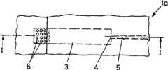
图1沿图2中线I-I截取的一个按本发明器具部件的剖面图, Fig. 1 cuts along line I-I in Fig. 2 by the sectional view of utensil parts of the present invention,
图2按照图1中箭头II的本发明第一种器具的俯视图, Fig. 2 is according to the top view of the first utensil of the present invention of arrow II among Fig. 1,
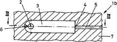
图3沿图4中的线III-III截取的一个按照本发明的第二种器具的剖面图, Fig. 3 cuts along a line III-III among Fig. 4 according to the sectional view of the second kind of utensil of the present invention,
图4沿图3中线IV-IV截取的按本发明的第二种器具的剖面图, Fig. 4 cuts along the sectional view of the second utensil of the present invention along line IV-IV in Fig. 3,
图5按本发明的第三种器具的一个透视立体图, Fig. 5 is by a perspective stereogram of the 3rd kind of utensil of the present invention,
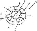
图6按本发明的第三种器具的俯视图, Fig. 6 is by the top view of the 3rd kind of utensil of the present invention,
图7沿图6中线VII-VII截取的按本发明的第三种器具的剖面图, Fig. 7 cuts along the sectional view of the third utensil of the present invention along line VII-VII in Fig. 6,
图8沿图6中线VIII-VIII截取的按本发明的第三种器具的剖面图, Fig. 8 cuts along the sectional view of the third utensil of the present invention along line VIII-VIII in Fig. 6,
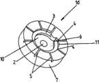
图9按本发明的第四种器具的透视图, Fig. 9 is by the perspective view of the 4th kind of utensil of the present invention,
图10按本发明的第四种器具的俯视图, Fig. 10 is by the top view of the 4th utensil of the present invention,
图11沿图10中线XI-XI截取的按本发明的第四种器具的剖面图, Fig. 11 cuts along the sectional view of the fourth utensil of the present invention along line XI-XI in Fig. 10,
图12沿图10中线XII-XII截取的按本发明的第四种器具的剖面图。 Fig. 12 is a sectional view of a fourth appliance according to the invention, taken along line XII-XII in Fig. 10 . the
在附图中示出的按本发明的器具具有部分特征,它们至少在其功能上相互一致。因此不同器具的相互功能上一致的特征用相同的附图标记标注。 The appliances according to the invention shown in the figures have partial features which at least correspond to one another in terms of their function. Mutually functionally identical features of different appliances are therefore marked with the same reference numerals. the
具体实施方式Detailed ways
在图1和图2中示出的第一种器具1a具有一个本体7,在该本体中制出一个凹槽。该凹槽形成一个过渡区3。一个通道从过渡区3开始延伸, 所述通道形成一个液体输出系统5。在此,液体输出系统5通过一个出口4连接到过渡区3上。过渡区3可以划分为两部分。一个远离出口4的第一部分具有柱形的第一微结构元件。该区域形成一个具有增高的毛细力的位置6。其余的朝向出口4的部分设计为没有特别的微结构元件。一个盖板8这样地覆盖过渡区3和液体输出系统5,使得在位置6的区域中一个入口2敞开,通过该入口可以将液体注入到过渡区3中。具有增高的毛细力的位置6的形成第一微结构元件的柱使得通过入口2注入到过渡区3的液体首先完全地停留在所述具有增高的毛细力的位置6上。液体没有通过位置6侵入很远,直到该位置6和限定该位置的过渡区表面例如盖板8的下侧、过渡区3的侧壁和过渡区3的底部被润湿。一旦位置6实现完全的和完整的润湿,也就是说在位置6上不再有空气,其他的通过入口2输入的液体保证,液体也进入到过渡区的朝向出口4的部分。在此,过渡区3朝向出口4的部分的润湿沿着边界面进行,所述边界面由盖板8的下侧、过渡区的侧壁和底部形成。沿着边界面的润湿保证,在朝向出口4的过渡区部分中的空气通过出口4从过渡区向外排挤,并且通过液体输出系统5从过渡区3中排出。一旦过渡区3完全用液体填满,液体同样通过出口4进入到液体输出系统中。为了改善在过渡区3中的液体流动特性并且尤其是加速液体的输送,可以在朝向出口4的过渡区3部分中设置一个斜面12作为第二微结构元件,该斜面把过渡区3底部的水平面向出口4升高到液体输出系统5的水平面。此外,整个过渡区3向着出口4的方向锥形地收缩,使得在出口4处没有产生过渡区3到液体输出系统5的跳跃式的横截面比率。 The first appliance 1a shown in FIGS. 1 and 2 has a
在按本发明的第一种器具中通过入口2注入的液体可以通过一个用作为液体输入系统的吸管或类似物输入。 In the first device according to the invention, the liquid injected through the
在图3和4中示出的按本发明的第二种器具1b同样具有一个本体7,在该本体中制出一个凹槽,该凹槽形成一个过渡区3。过渡区3具有一个入口2,在该入口中一个由通道构成的液体输入系统9通入到过渡区3中。此外,过渡区3还具有一个出口4,从该出口起一个由通道构成的液体输出系统5开始延伸。在此,该出口4设置在过渡区3的一个侧向的 边界面中,而且设置在过渡区3的一个与入口2相对置的末端上。本体7和因此整个过渡区3以及液体输出系统5用盖板8覆盖。 The
在入口2的区域中的过渡区的起始端处,过渡区3具有一个位置6,该位置具有增高的毛细力。该位置6由一个缺口构成,它使得从液体输入系统9流入的液体由于在位置6处增高的毛细力首先润湿位置6,并且从那里开始过渡区3沿着侧向的边界面、盖板8的下侧和过渡区3的底部润湿。然后一个液体弯月面由于作用的毛细力从入口2经由具有增高的毛细力的位置6沿过渡区3移动到出口4,并且首先把包含在过渡区3中的气体推到出口4。由此产生一个从液体输入系统9经位置6和其余的过渡区3到出口4的流动,其中防止在过渡区3和液体输出系统的内部形成气泡。因此例如液体流能够绕90°的转向而在器具内没有形成气泡。 At the start of the transition zone in the region of the
当然通过一个合适的器具达到液体流绕比90°更大或更小的角度的转向同样也是可能的,其中在此保证,液体的弯月面通过过渡区移动到更宽的正面,并且完全地润湿多个壁以及侧向的边界面、盖板8的底侧和过渡区的底部,并且包含在过渡区3中的空气首先被排挤到液体输出系统5中,使得在过渡区3或液体输出系统5中没有残留气泡。 Of course, it is also possible to achieve a deflection of the liquid flow around an angle larger or smaller than 90° by means of a suitable device, wherein it is ensured here that the meniscus of the liquid moves over the transition region to a wider front and completely Wet the walls and the lateral boundary surfaces, the underside of the
在图5至8中示出的按本发明的第三种器具1c具有一个基本上圆柱形的本体7。该本体7具有一个中心孔,该中心孔形成一个液体输入系统9并且以一个入口2通入到一个腔室中,该腔室由一个汇集区10和包围汇集区10的过渡区3构成。该腔室作为一个凹槽设置在本体7的端面上,其中汇集区10完全包围入口2地直接邻接入口2。过渡区3通过一个由一个凸缘构成的毛细阻塞11邻接汇集区10。在此,凸缘这样地设计,使得汇集区10凸出于过渡区3。 A
因此,过渡区3基本上环形地包围汇集区10,其中该环在过渡区3的始端和末端之间具有一个隔断。过渡区3的始端和末端通过一个突起部相互地隔开,该突起部形成所述基本上环形的过渡区3的隔断。 The
在过渡区的始端和过渡区3的末端之间从过渡区径向向外地分支出多个通道,所述通道构成液体输出系统5。所述液体输出系统5通过出口4与过渡区3连接。 Between the beginning of the transition zone and the end of the
过渡区3的始端包括一个具有增高的毛细力的位置6。该具有增高的毛细力的位置6由一个缺口形成,该缺口在汇集区10和过渡区3之间邻接毛细阻塞(Kapillarstopp)11。这个作为器具的一个第一微结构元件的缺口使得通过入口2进入到汇集区10中的液体由于作用的增高的毛细力吸到过渡区3的起始处。在液体继续侵入到过渡区3中之前,所述具有增高的毛细力的位置6继续使过渡区3的始端被完全地润湿。 The beginning of the
在过渡区3的始端完全被液体润湿之后,继续在过渡区3中作用的其他毛细力使得液体沿着过渡区输送,其中形成毛细阻塞11的凸缘被润湿,并且由此消除了毛细阻塞11。液体沿着过渡区3移动并在此润湿多个出口4,使得液体可以进入到多个液体输出系统5中。在过渡区3中的空气通过出口4和液体输出系统从过渡区3并且在必要时也从汇集区10中排挤出。因此在过渡区3和汇集区10中都没有残留气泡。因此能够实现无气泡地填充液体输出系统。 After the beginning of the
根据图9至12的按本发明的器具1d的第四实施例基本上与根据图5至8的第三实施例的结构相一致。按本发明的第三种器具和按本发明的第四种器具之间的区别基本上在于,与按本发明的第三种器具不同,在按本发明的第四种器具中汇集区10比基本上环形的过渡区3更深。这就是说,过渡区3凸出于汇集区10。在汇集区10和过渡区3之间的一个凸缘仍然形成一个毛细阻塞11,该毛细阻塞仅仅防止液体由于毛细力从汇集区10进入到过渡区3中。一个缺口形成位置6,该位置位于过渡区3的始端并且具有一个增高的毛细力。该位置6促使得过渡区3始端的润湿。所述具有增高的毛细力的位置6由一个第一微结构元件形成,它由一个缺口形成,该缺口在汇集区10和过渡区3之间邻接毛细阻塞11。所述具有增高的毛细力的位置6使得从入口2进入到汇集区10中的液体首先只润湿过渡区3的始端,并且然后一个液体弯月面沿着过渡区3从其始端移动到其末端,它逐渐地消除向汇集区10的毛细阻塞11,并且润湿多个出口4,使得液体也可以进入到液体输出系统中。位于过渡区3中和必要时还位于汇集区10中的空气通过出口4同时被排挤到多个液体输出区域5中,使得紧接着在汇集区10和过渡区3以及多个液体输出区域5中没有残留气泡。由此保证无气泡地填充液体输出系统。 The fourth exemplary embodiment of a
Claims (28)
Applications Claiming Priority (2)
| Application Number | Priority Date | Filing Date | Title |
|---|---|---|---|
| DE10360220.8 | 2003-12-20 | ||
| DE10360220ADE10360220A1 (en) | 2003-12-20 | 2003-12-20 | Fine structure arrangement in fluid ejection system, has predetermined region in transitional zone between inlet and discharge ports, at which capillary force is maximum |
Related Parent Applications (1)
| Application Number | Title | Priority Date | Filing Date |
|---|---|---|---|
| CNA2004100942165ADivisionCN1695808A (en) | 2003-12-20 | 2004-12-20 | Microstructured device, device with such device and filling method |
Publications (2)
| Publication Number | Publication Date |
|---|---|
| CN101632947A CN101632947A (en) | 2010-01-27 |
| CN101632947Btrue CN101632947B (en) | 2012-08-08 |
Family
ID=34638731
Family Applications (2)
| Application Number | Title | Priority Date | Filing Date |
|---|---|---|---|
| CNA2004100942165APendingCN1695808A (en) | 2003-12-20 | 2004-12-20 | Microstructured device, device with such device and filling method |
| CN2009101603255AExpired - LifetimeCN101632947B (en) | 2003-12-20 | 2004-12-20 | Microstructure arrangement for the bubble-free filling with a liquid of at least one system for draining off liquids |
Family Applications Before (1)
| Application Number | Title | Priority Date | Filing Date |
|---|---|---|---|
| CNA2004100942165APendingCN1695808A (en) | 2003-12-20 | 2004-12-20 | Microstructured device, device with such device and filling method |
Country Status (5)
| Country | Link |
|---|---|
| US (1) | US7485118B2 (en) |
| EP (1) | EP1559676B1 (en) |
| JP (1) | JP4931345B2 (en) |
| CN (2) | CN1695808A (en) |
| DE (1) | DE10360220A1 (en) |
Families Citing this family (23)
| Publication number | Priority date | Publication date | Assignee | Title |
|---|---|---|---|---|
| US20070280856A1 (en)* | 2006-06-02 | 2007-12-06 | Applera Corporation | Devices and Methods for Controlling Bubble Formation in Microfluidic Devices |
| US20070280857A1 (en)* | 2006-06-02 | 2007-12-06 | Applera Corporation | Devices and Methods for Positioning Dried Reagent In Microfluidic Devices |
| EP1977829A1 (en)* | 2007-03-29 | 2008-10-08 | Roche Diagnostics GmbH | Device for performing multiple analyses in parallel |
| EP3521833B1 (en) | 2007-10-30 | 2021-05-26 | PHC Holdings Corporation | Analyzing device |
| JP5059880B2 (en)* | 2008-02-01 | 2012-10-31 | 日本電信電話株式会社 | Flow cell |
| CA2716411C (en)* | 2008-02-27 | 2015-11-24 | Boehringer Ingelheim Microparts Gmbh | Apparatus for the separation of plasma |
| US10005082B2 (en) | 2008-04-11 | 2018-06-26 | Incyto Co., Ltd. | Microfluidic circuit element comprising microfluidic channel with nano interstices and fabrication method thereof |
| KR100998535B1 (en)* | 2008-04-11 | 2010-12-07 | 인싸이토 주식회사 | Microfluidic circuit device equipped with microfluidic channel having nanogap and manufacturing method thereof |
| KR101390717B1 (en) | 2008-09-02 | 2014-04-30 | 삼성전자주식회사 | Microfluidic device and method of loading sample thereto |
| EP2213364A1 (en)* | 2009-01-30 | 2010-08-04 | Albert-Ludwigs-Universität Freiburg | Phase guide patterns for liquid manipulation |
| US20120040445A1 (en)* | 2009-04-15 | 2012-02-16 | Koninklijke Philips Electronics N.V. | Gas-free fluid chamber |
| EP2486978A1 (en) | 2010-10-28 | 2012-08-15 | Roche Diagnostics GmbH | Microfluid test carrier for separating a fluid volume in partial volumes |
| EP2455162A1 (en)* | 2010-10-29 | 2012-05-23 | Roche Diagnostics GmbH | Microfluidic element for analysing a fluid sample |
| WO2013004673A1 (en) | 2011-07-05 | 2013-01-10 | Boehringer Ingelheim Microparts Gmbh | Microfluidic structure having recesses |
| US10058866B2 (en) | 2013-03-13 | 2018-08-28 | Abbott Laboratories | Methods and apparatus to mitigate bubble formation in a liquid |
| USD962471S1 (en) | 2013-03-13 | 2022-08-30 | Abbott Laboratories | Reagent container |
| US9535082B2 (en) | 2013-03-13 | 2017-01-03 | Abbott Laboratories | Methods and apparatus to agitate a liquid |
| USD978375S1 (en) | 2013-03-13 | 2023-02-14 | Abbott Laboratories | Reagent container |
| WO2017117553A1 (en)* | 2015-12-31 | 2017-07-06 | Mec Dynamics | Micro mechanical methods and systems for performing assays |
| US10258741B2 (en) | 2016-12-28 | 2019-04-16 | Cequr Sa | Microfluidic flow restrictor and system |
| WO2018127293A1 (en)* | 2017-01-09 | 2018-07-12 | Huawei Technologies Co., Ltd. | Electro hydro dynamic apparatus and system comprising an electro hydro dynamic apparatus |
| CN108722504A (en)* | 2017-04-19 | 2018-11-02 | 光宝电子(广州)有限公司 | Detection device and its injection mouth structure |
| KR102012243B1 (en)* | 2017-09-19 | 2019-11-04 | 한국기계연구원 | Micro Fluid Element having Micro Sub Flow Paths and Mold for Manufacturing the Same |
Citations (2)
| Publication number | Priority date | Publication date | Assignee | Title |
|---|---|---|---|---|
| CN1326549A (en)* | 1998-10-13 | 2001-12-12 | 微生物系统公司 | Fluid circuit components based upon passive fluid dynamics |
| US20020114738A1 (en)* | 2000-10-25 | 2002-08-22 | Wyzgol Raimund C. | Structures for precisely controlled transport of fluids |
Family Cites Families (33)
| Publication number | Priority date | Publication date | Assignee | Title |
|---|---|---|---|---|
| US4233029A (en)* | 1978-10-25 | 1980-11-11 | Eastman Kodak Company | Liquid transport device and method |
| US4310399A (en)* | 1979-07-23 | 1982-01-12 | Eastman Kodak Company | Liquid transport device containing means for delaying capillary flow |
| US4271119A (en)* | 1979-07-23 | 1981-06-02 | Eastman Kodak Company | Capillary transport device having connected transport zones |
| GB2090659A (en)* | 1981-01-02 | 1982-07-14 | Instrumentation Labor Inc | Analytical device |
| US4426451A (en)* | 1981-01-28 | 1984-01-17 | Eastman Kodak Company | Multi-zoned reaction vessel having pressure-actuatable control means between zones |
| US4473457A (en)* | 1982-03-29 | 1984-09-25 | Eastman Kodak Company | Liquid transport device providing diversion of capillary flow into a non-vented second zone |
| US4549952A (en)* | 1982-11-22 | 1985-10-29 | Eastman Kodak Company | Capillary transport device having means for increasing the viscosity of the transported liquid |
| US4618476A (en)* | 1984-02-10 | 1986-10-21 | Eastman Kodak Company | Capillary transport device having speed and meniscus control means |
| US4963498A (en)* | 1985-08-05 | 1990-10-16 | Biotrack | Capillary flow device |
| DE3851458T2 (en)* | 1987-04-08 | 1995-02-09 | Hitachi Ltd | Device with a vaginal flow cell. |
| JPS63262565A (en)* | 1987-04-20 | 1988-10-28 | Hitachi Ltd | flow cell |
| US5051237A (en)* | 1988-06-23 | 1991-09-24 | P B Diagnostic Systems, Inc. | Liquid transport system |
| US4957582A (en)* | 1989-03-16 | 1990-09-18 | Eastman Kodak Company | Capillary transport zone coated with adhesive |
| US5039617A (en)* | 1989-04-20 | 1991-08-13 | Biotrack, Inc. | Capillary flow device and method for measuring activated partial thromboplastin time |
| US5230866A (en)* | 1991-03-01 | 1993-07-27 | Biotrack, Inc. | Capillary stop-flow junction having improved stability against accidental fluid flow |
| US5744366A (en)* | 1992-05-01 | 1998-04-28 | Trustees Of The University Of Pennsylvania | Mesoscale devices and methods for analysis of motile cells |
| US5885527A (en)* | 1992-05-21 | 1999-03-23 | Biosite Diagnostics, Inc. | Diagnostic devices and apparatus for the controlled movement of reagents without membrances |
| US6156270A (en)* | 1992-05-21 | 2000-12-05 | Biosite Diagnostics, Inc. | Diagnostic devices and apparatus for the controlled movement of reagents without membranes |
| US5591643A (en)* | 1993-09-01 | 1997-01-07 | Abaxis, Inc. | Simplified inlet channels |
| GB9509487D0 (en)* | 1995-05-10 | 1995-07-05 | Ici Plc | Micro relief element & preparation thereof |
| US6143248A (en)* | 1996-08-12 | 2000-11-07 | Gamera Bioscience Corp. | Capillary microvalve |
| US6113855A (en)* | 1996-11-15 | 2000-09-05 | Biosite Diagnostics, Inc. | Devices comprising multiple capillarity inducing surfaces |
| DE19753849A1 (en)* | 1997-12-04 | 1999-06-10 | Roche Diagnostics Gmbh | Analytical test element with a tapered capillary channel |
| EP1058697B1 (en) | 1998-03-05 | 2008-11-26 | E.I. Du Pont De Nemours And Company | Polymeric films having controlled viscosity response to temperature and shear |
| AU739563B2 (en)* | 1998-03-11 | 2001-10-18 | Boehringer Ingelheim Microparts Gmbh | Sample support |
| DE19859693A1 (en)* | 1998-12-23 | 2000-06-29 | Microparts Gmbh | Device for draining a liquid from capillaries |
| US6193471B1 (en)* | 1999-06-30 | 2001-02-27 | Perseptive Biosystems, Inc. | Pneumatic control of formation and transport of small volume liquid samples |
| US6743399B1 (en)* | 1999-10-08 | 2004-06-01 | Micronics, Inc. | Pumpless microfluidics |
| FR2812306B1 (en)* | 2000-07-28 | 2005-01-14 | Gabriel Festoc | POLYMERSIS CHAIN AMPLIFICATION SYSTEM OF TARGET NUCLEIC SEQUENCES |
| US6653122B2 (en)* | 2001-04-24 | 2003-11-25 | Dade Microscan Inc. | Indentification test device in a random access microbiological analyzer |
| WO2003025547A1 (en)* | 2001-09-21 | 2003-03-27 | Biomedlab Corporation | Method and device for screening analytes using surface plasmon resonance |
| US20040042930A1 (en)* | 2002-08-30 | 2004-03-04 | Clemens Charles E. | Reaction chamber with capillary lock for fluid positioning and retention |
| US20040265172A1 (en)* | 2003-06-27 | 2004-12-30 | Pugia Michael J. | Method and apparatus for entry and storage of specimens into a microfluidic device |
- 2003
- 2003-12-20DEDE10360220Apatent/DE10360220A1/ennot_activeCeased
- 2004
- 2004-12-15EPEP04029633.7Apatent/EP1559676B1/ennot_activeExpired - Lifetime
- 2004-12-20USUS11/015,333patent/US7485118B2/enactiveActive
- 2004-12-20CNCNA2004100942165Apatent/CN1695808A/enactivePending
- 2004-12-20JPJP2004368438Apatent/JP4931345B2/ennot_activeExpired - Lifetime
- 2004-12-20CNCN2009101603255Apatent/CN101632947B/ennot_activeExpired - Lifetime
Patent Citations (2)
| Publication number | Priority date | Publication date | Assignee | Title |
|---|---|---|---|---|
| CN1326549A (en)* | 1998-10-13 | 2001-12-12 | 微生物系统公司 | Fluid circuit components based upon passive fluid dynamics |
| US20020114738A1 (en)* | 2000-10-25 | 2002-08-22 | Wyzgol Raimund C. | Structures for precisely controlled transport of fluids |
Also Published As
| Publication number | Publication date |
|---|---|
| CN1695808A (en) | 2005-11-16 |
| US7485118B2 (en) | 2009-02-03 |
| EP1559676B1 (en) | 2016-06-29 |
| US20050169778A1 (en) | 2005-08-04 |
| JP2005177754A (en) | 2005-07-07 |
| CN101632947A (en) | 2010-01-27 |
| EP1559676A2 (en) | 2005-08-03 |
| DE10360220A1 (en) | 2005-07-21 |
| EP1559676A3 (en) | 2008-12-03 |
| JP4931345B2 (en) | 2012-05-16 |
Similar Documents
| Publication | Publication Date | Title |
|---|---|---|
| CN101632947B (en) | Microstructure arrangement for the bubble-free filling with a liquid of at least one system for draining off liquids | |
| EP1682438B1 (en) | Multilayer hydrodynamic sheath flow structure | |
| JP3978189B2 (en) | Semiconductor device manufacturing method and manufacturing apparatus thereof | |
| US11648555B2 (en) | Domino capillary microfluidic circuit | |
| CA2359787A1 (en) | Devices for the analysis of fluids and controlled transport of fluids | |
| JP2004283828A (en) | Microstructure separation apparatus and microfluidic method for separating liquid components from a liquid containing particles | |
| US11911763B2 (en) | Microfluidic device and methods | |
| CN103517762A (en) | Control of liquid flow sequence on microfluidic device | |
| JP6573175B2 (en) | Separation apparatus, fluid device, separation method and mixing method | |
| AU2021254626A1 (en) | An arrangement for mixing fluids in a capillary driven fluidic system | |
| JPH03106411A (en) | Device for separating solid particles and high density fluid from low density fluid | |
| CN1278640C (en) | Cleaning device for a shaving head of a dry shaving apparatus | |
| KR101809071B1 (en) | Bubble removing device at the fluid to move micro channel and bubble removing method thereof | |
| US20210170408A1 (en) | Microfluidic valves | |
| KR102012242B1 (en) | Cover of microfluidic device, method of making the same cover and microfluidic device having the same cover | |
| AU2011205167B9 (en) | Multilayer hydrodynamic sheath flow structure | |
| US11578480B2 (en) | Grease interceptor and method of use thereof | |
| KR200357456Y1 (en) | A funnel | |
| KR20250045971A (en) | Microfluidic chip | |
| CN117443469A (en) | Microfluidic devices and fractionation methods |
Legal Events
| Date | Code | Title | Description |
|---|---|---|---|
| C06 | Publication | ||
| PB01 | Publication | ||
| C10 | Entry into substantive examination | ||
| SE01 | Entry into force of request for substantive examination | ||
| C14 | Grant of patent or utility model | ||
| GR01 | Patent grant | ||
| CX01 | Expiry of patent term | ||
| CX01 | Expiry of patent term | Granted publication date:20120808 |