CN101632113B - Calibration of displays having spatially-variable backlight - Google Patents
Calibration of displays having spatially-variable backlightDownload PDFInfo
- Publication number
- CN101632113B CN101632113BCN2008800082080ACN200880008208ACN101632113BCN 101632113 BCN101632113 BCN 101632113BCN 2008800082080 ACN2008800082080 ACN 2008800082080ACN 200880008208 ACN200880008208 ACN 200880008208ACN 101632113 BCN101632113 BCN 101632113B
- Authority
- CN
- China
- Prior art keywords
- light
- light source
- intensity
- controller
- indication
- Prior art date
- Legal status (The legal status is an assumption and is not a legal conclusion. Google has not performed a legal analysis and makes no representation as to the accuracy of the status listed.)
- Active
Links
- 238000012937correctionMethods0.000claimsdescription68
- 238000000034methodMethods0.000claimsdescription59
- 238000005259measurementMethods0.000claimsdescription14
- 230000004044responseEffects0.000claimsdescription13
- 238000001228spectrumMethods0.000claimsdescription13
- 230000006870functionEffects0.000claimsdescription12
- 230000008859changeEffects0.000claimsdescription6
- 238000012360testing methodMethods0.000description35
- 230000003287optical effectEffects0.000description8
- 230000007246mechanismEffects0.000description5
- 238000004088simulationMethods0.000description4
- 238000009826distributionMethods0.000description3
- 230000008569processEffects0.000description3
- 230000035945sensitivityEffects0.000description3
- 239000003086colorantSubstances0.000description2
- 238000001914filtrationMethods0.000description2
- 238000012986modificationMethods0.000description2
- 230000004048modificationEffects0.000description2
- 230000003595spectral effectEffects0.000description2
- OAICVXFJPJFONN-UHFFFAOYSA-NPhosphorusChemical compound[P]OAICVXFJPJFONN-UHFFFAOYSA-N0.000description1
- 230000008901benefitEffects0.000description1
- 230000008878couplingEffects0.000description1
- 238000010168coupling processMethods0.000description1
- 238000005859coupling reactionMethods0.000description1
- 230000003247decreasing effectEffects0.000description1
- 238000010586diagramMethods0.000description1
- 238000005286illuminationMethods0.000description1
- 238000004519manufacturing processMethods0.000description1
- 238000012545processingMethods0.000description1
- 230000009467reductionEffects0.000description1
- 238000003860storageMethods0.000description1
- 239000000126substanceSubstances0.000description1
- 238000002834transmittanceMethods0.000description1
Images


Classifications
- G—PHYSICS
- G09—EDUCATION; CRYPTOGRAPHY; DISPLAY; ADVERTISING; SEALS
- G09G—ARRANGEMENTS OR CIRCUITS FOR CONTROL OF INDICATING DEVICES USING STATIC MEANS TO PRESENT VARIABLE INFORMATION
- G09G3/00—Control arrangements or circuits, of interest only in connection with visual indicators other than cathode-ray tubes
- G09G3/20—Control arrangements or circuits, of interest only in connection with visual indicators other than cathode-ray tubes for presentation of an assembly of a number of characters, e.g. a page, by composing the assembly by combination of individual elements arranged in a matrix no fixed position being assigned to or needed to be assigned to the individual characters or partial characters
- G09G3/34—Control arrangements or circuits, of interest only in connection with visual indicators other than cathode-ray tubes for presentation of an assembly of a number of characters, e.g. a page, by composing the assembly by combination of individual elements arranged in a matrix no fixed position being assigned to or needed to be assigned to the individual characters or partial characters by control of light from an independent source
- G09G3/3406—Control of illumination source
- G09G3/342—Control of illumination source using several illumination sources separately controlled corresponding to different display panel areas, e.g. along one dimension such as lines
- G09G3/3426—Control of illumination source using several illumination sources separately controlled corresponding to different display panel areas, e.g. along one dimension such as lines the different display panel areas being distributed in two dimensions, e.g. matrix
- G—PHYSICS
- G09—EDUCATION; CRYPTOGRAPHY; DISPLAY; ADVERTISING; SEALS
- G09G—ARRANGEMENTS OR CIRCUITS FOR CONTROL OF INDICATING DEVICES USING STATIC MEANS TO PRESENT VARIABLE INFORMATION
- G09G3/00—Control arrangements or circuits, of interest only in connection with visual indicators other than cathode-ray tubes
- G09G3/20—Control arrangements or circuits, of interest only in connection with visual indicators other than cathode-ray tubes for presentation of an assembly of a number of characters, e.g. a page, by composing the assembly by combination of individual elements arranged in a matrix no fixed position being assigned to or needed to be assigned to the individual characters or partial characters
- G09G3/22—Control arrangements or circuits, of interest only in connection with visual indicators other than cathode-ray tubes for presentation of an assembly of a number of characters, e.g. a page, by composing the assembly by combination of individual elements arranged in a matrix no fixed position being assigned to or needed to be assigned to the individual characters or partial characters using controlled light sources
- G—PHYSICS
- G02—OPTICS
- G02F—OPTICAL DEVICES OR ARRANGEMENTS FOR THE CONTROL OF LIGHT BY MODIFICATION OF THE OPTICAL PROPERTIES OF THE MEDIA OF THE ELEMENTS INVOLVED THEREIN; NON-LINEAR OPTICS; FREQUENCY-CHANGING OF LIGHT; OPTICAL LOGIC ELEMENTS; OPTICAL ANALOGUE/DIGITAL CONVERTERS
- G02F1/00—Devices or arrangements for the control of the intensity, colour, phase, polarisation or direction of light arriving from an independent light source, e.g. switching, gating or modulating; Non-linear optics
- G02F1/01—Devices or arrangements for the control of the intensity, colour, phase, polarisation or direction of light arriving from an independent light source, e.g. switching, gating or modulating; Non-linear optics for the control of the intensity, phase, polarisation or colour
- G02F1/13—Devices or arrangements for the control of the intensity, colour, phase, polarisation or direction of light arriving from an independent light source, e.g. switching, gating or modulating; Non-linear optics for the control of the intensity, phase, polarisation or colour based on liquid crystals, e.g. single liquid crystal display cells
- G02F1/133—Constructional arrangements; Operation of liquid crystal cells; Circuit arrangements
- G—PHYSICS
- G09—EDUCATION; CRYPTOGRAPHY; DISPLAY; ADVERTISING; SEALS
- G09G—ARRANGEMENTS OR CIRCUITS FOR CONTROL OF INDICATING DEVICES USING STATIC MEANS TO PRESENT VARIABLE INFORMATION
- G09G3/00—Control arrangements or circuits, of interest only in connection with visual indicators other than cathode-ray tubes
- G09G3/20—Control arrangements or circuits, of interest only in connection with visual indicators other than cathode-ray tubes for presentation of an assembly of a number of characters, e.g. a page, by composing the assembly by combination of individual elements arranged in a matrix no fixed position being assigned to or needed to be assigned to the individual characters or partial characters
- G09G3/34—Control arrangements or circuits, of interest only in connection with visual indicators other than cathode-ray tubes for presentation of an assembly of a number of characters, e.g. a page, by composing the assembly by combination of individual elements arranged in a matrix no fixed position being assigned to or needed to be assigned to the individual characters or partial characters by control of light from an independent source
- G09G3/36—Control arrangements or circuits, of interest only in connection with visual indicators other than cathode-ray tubes for presentation of an assembly of a number of characters, e.g. a page, by composing the assembly by combination of individual elements arranged in a matrix no fixed position being assigned to or needed to be assigned to the individual characters or partial characters by control of light from an independent source using liquid crystals
- G—PHYSICS
- G02—OPTICS
- G02F—OPTICAL DEVICES OR ARRANGEMENTS FOR THE CONTROL OF LIGHT BY MODIFICATION OF THE OPTICAL PROPERTIES OF THE MEDIA OF THE ELEMENTS INVOLVED THEREIN; NON-LINEAR OPTICS; FREQUENCY-CHANGING OF LIGHT; OPTICAL LOGIC ELEMENTS; OPTICAL ANALOGUE/DIGITAL CONVERTERS
- G02F1/00—Devices or arrangements for the control of the intensity, colour, phase, polarisation or direction of light arriving from an independent light source, e.g. switching, gating or modulating; Non-linear optics
- G02F1/01—Devices or arrangements for the control of the intensity, colour, phase, polarisation or direction of light arriving from an independent light source, e.g. switching, gating or modulating; Non-linear optics for the control of the intensity, phase, polarisation or colour
- G02F1/13—Devices or arrangements for the control of the intensity, colour, phase, polarisation or direction of light arriving from an independent light source, e.g. switching, gating or modulating; Non-linear optics for the control of the intensity, phase, polarisation or colour based on liquid crystals, e.g. single liquid crystal display cells
- G02F1/133—Constructional arrangements; Operation of liquid crystal cells; Circuit arrangements
- G02F1/1333—Constructional arrangements; Manufacturing methods
- G02F1/1335—Structural association of cells with optical devices, e.g. polarisers or reflectors
- G02F1/1336—Illuminating devices
- G02F1/133602—Direct backlight
- G02F1/133603—Direct backlight with LEDs
- G—PHYSICS
- G02—OPTICS
- G02F—OPTICAL DEVICES OR ARRANGEMENTS FOR THE CONTROL OF LIGHT BY MODIFICATION OF THE OPTICAL PROPERTIES OF THE MEDIA OF THE ELEMENTS INVOLVED THEREIN; NON-LINEAR OPTICS; FREQUENCY-CHANGING OF LIGHT; OPTICAL LOGIC ELEMENTS; OPTICAL ANALOGUE/DIGITAL CONVERTERS
- G02F1/00—Devices or arrangements for the control of the intensity, colour, phase, polarisation or direction of light arriving from an independent light source, e.g. switching, gating or modulating; Non-linear optics
- G02F1/01—Devices or arrangements for the control of the intensity, colour, phase, polarisation or direction of light arriving from an independent light source, e.g. switching, gating or modulating; Non-linear optics for the control of the intensity, phase, polarisation or colour
- G02F1/13—Devices or arrangements for the control of the intensity, colour, phase, polarisation or direction of light arriving from an independent light source, e.g. switching, gating or modulating; Non-linear optics for the control of the intensity, phase, polarisation or colour based on liquid crystals, e.g. single liquid crystal display cells
- G02F1/133—Constructional arrangements; Operation of liquid crystal cells; Circuit arrangements
- G02F1/1333—Constructional arrangements; Manufacturing methods
- G02F1/1335—Structural association of cells with optical devices, e.g. polarisers or reflectors
- G02F1/1336—Illuminating devices
- G02F1/133602—Direct backlight
- G02F1/133612—Electrical details
- G—PHYSICS
- G02—OPTICS
- G02F—OPTICAL DEVICES OR ARRANGEMENTS FOR THE CONTROL OF LIGHT BY MODIFICATION OF THE OPTICAL PROPERTIES OF THE MEDIA OF THE ELEMENTS INVOLVED THEREIN; NON-LINEAR OPTICS; FREQUENCY-CHANGING OF LIGHT; OPTICAL LOGIC ELEMENTS; OPTICAL ANALOGUE/DIGITAL CONVERTERS
- G02F1/00—Devices or arrangements for the control of the intensity, colour, phase, polarisation or direction of light arriving from an independent light source, e.g. switching, gating or modulating; Non-linear optics
- G02F1/01—Devices or arrangements for the control of the intensity, colour, phase, polarisation or direction of light arriving from an independent light source, e.g. switching, gating or modulating; Non-linear optics for the control of the intensity, phase, polarisation or colour
- G02F1/13—Devices or arrangements for the control of the intensity, colour, phase, polarisation or direction of light arriving from an independent light source, e.g. switching, gating or modulating; Non-linear optics for the control of the intensity, phase, polarisation or colour based on liquid crystals, e.g. single liquid crystal display cells
- G02F1/133—Constructional arrangements; Operation of liquid crystal cells; Circuit arrangements
- G02F1/1333—Constructional arrangements; Manufacturing methods
- G02F1/1335—Structural association of cells with optical devices, e.g. polarisers or reflectors
- G02F1/1336—Illuminating devices
- G02F1/133621—Illuminating devices providing coloured light
- G02F1/133622—Colour sequential illumination
- G—PHYSICS
- G02—OPTICS
- G02F—OPTICAL DEVICES OR ARRANGEMENTS FOR THE CONTROL OF LIGHT BY MODIFICATION OF THE OPTICAL PROPERTIES OF THE MEDIA OF THE ELEMENTS INVOLVED THEREIN; NON-LINEAR OPTICS; FREQUENCY-CHANGING OF LIGHT; OPTICAL LOGIC ELEMENTS; OPTICAL ANALOGUE/DIGITAL CONVERTERS
- G02F2201/00—Constructional arrangements not provided for in groups G02F1/00 - G02F7/00
- G02F2201/58—Arrangements comprising a monitoring photodetector
- G—PHYSICS
- G09—EDUCATION; CRYPTOGRAPHY; DISPLAY; ADVERTISING; SEALS
- G09G—ARRANGEMENTS OR CIRCUITS FOR CONTROL OF INDICATING DEVICES USING STATIC MEANS TO PRESENT VARIABLE INFORMATION
- G09G2320/00—Control of display operating conditions
- G09G2320/02—Improving the quality of display appearance
- G09G2320/0233—Improving the luminance or brightness uniformity across the screen
- G—PHYSICS
- G09—EDUCATION; CRYPTOGRAPHY; DISPLAY; ADVERTISING; SEALS
- G09G—ARRANGEMENTS OR CIRCUITS FOR CONTROL OF INDICATING DEVICES USING STATIC MEANS TO PRESENT VARIABLE INFORMATION
- G09G2320/00—Control of display operating conditions
- G09G2320/02—Improving the quality of display appearance
- G09G2320/0285—Improving the quality of display appearance using tables for spatial correction of display data
- G—PHYSICS
- G09—EDUCATION; CRYPTOGRAPHY; DISPLAY; ADVERTISING; SEALS
- G09G—ARRANGEMENTS OR CIRCUITS FOR CONTROL OF INDICATING DEVICES USING STATIC MEANS TO PRESENT VARIABLE INFORMATION
- G09G2320/00—Control of display operating conditions
- G09G2320/04—Maintaining the quality of display appearance
- G09G2320/043—Preventing or counteracting the effects of ageing
- G—PHYSICS
- G09—EDUCATION; CRYPTOGRAPHY; DISPLAY; ADVERTISING; SEALS
- G09G—ARRANGEMENTS OR CIRCUITS FOR CONTROL OF INDICATING DEVICES USING STATIC MEANS TO PRESENT VARIABLE INFORMATION
- G09G2320/00—Control of display operating conditions
- G09G2320/06—Adjustment of display parameters
- G09G2320/0626—Adjustment of display parameters for control of overall brightness
- G09G2320/064—Adjustment of display parameters for control of overall brightness by time modulation of the brightness of the illumination source
- G—PHYSICS
- G09—EDUCATION; CRYPTOGRAPHY; DISPLAY; ADVERTISING; SEALS
- G09G—ARRANGEMENTS OR CIRCUITS FOR CONTROL OF INDICATING DEVICES USING STATIC MEANS TO PRESENT VARIABLE INFORMATION
- G09G2320/00—Control of display operating conditions
- G09G2320/06—Adjustment of display parameters
- G09G2320/0693—Calibration of display systems
- G—PHYSICS
- G09—EDUCATION; CRYPTOGRAPHY; DISPLAY; ADVERTISING; SEALS
- G09G—ARRANGEMENTS OR CIRCUITS FOR CONTROL OF INDICATING DEVICES USING STATIC MEANS TO PRESENT VARIABLE INFORMATION
- G09G2360/00—Aspects of the architecture of display systems
- G09G2360/14—Detecting light within display terminals, e.g. using a single or a plurality of photosensors
- G09G2360/145—Detecting light within display terminals, e.g. using a single or a plurality of photosensors the light originating from the display screen
Landscapes
- Physics & Mathematics (AREA)
- Engineering & Computer Science (AREA)
- General Physics & Mathematics (AREA)
- Computer Hardware Design (AREA)
- Theoretical Computer Science (AREA)
- Chemical & Material Sciences (AREA)
- Crystallography & Structural Chemistry (AREA)
- Nonlinear Science (AREA)
- Mathematical Physics (AREA)
- Optics & Photonics (AREA)
- Control Of Indicators Other Than Cathode Ray Tubes (AREA)
- Circuit Arrangement For Electric Light Sources In General (AREA)
- Liquid Crystal Display Device Control (AREA)
- Liquid Crystal (AREA)
- Devices For Indicating Variable Information By Combining Individual Elements (AREA)
Abstract
Translated fromChinese
Description
Translated fromChinese相关申请的交叉引用Cross References to Related Applications
本申请要求提交于2007年2月1日的名称为“具有空间可变背光的显示器的校准”(CALIBRATION OF DISPLAYS HAVINGSPATIALLY-VARIABLE BACKLIGHT)美国临时申请第60/899,098号的权益,通过引用将其完整结合在此。This application claims the benefit of U.S. Provisional Application No. 60/899,098, entitled "CALIBRATION OF DISPLAYS HAVING SPATIALLY-VARIABLE BACKLIGHT," filed February 1, 2007, which is incorporated by reference in its entirety combined here.
技术领域technical field
本发明涉及显示数字图像的显示器的校准。The invention relates to the calibration of displays for displaying digital images.
背景技术Background technique
用于显示数字图像的某些类型的显示器包括多个可单独控制的光源。这种显示器的例子包括国际申请No.PCT/CA03/00350中所描述的显示器,通过引用将该国际申请结合在此。例如,这种显示器可以使用发光二极管(LED)作为可单独控制的光源。Certain types of displays for displaying digital images include multiple individually controllable light sources. Examples of such displays include those described in International Application No. PCT/CA03/00350, which is hereby incorporated by reference. For example, such displays may use light emitting diodes (LEDs) as individually controllable light sources.
使用LED作为光源的一个问题是在特定驱动电流水平下发出的光量可能在各个LED之间显著地改变。这种改变可能是由生产过程变化引起的。另外,各个LED对于任何给定驱动电流将产生的光量趋向于随着LED老化而以不可预测的方式缓慢减小。One problem with using LEDs as light sources is that the amount of light emitted at a particular drive current level can vary significantly from LED to LED. Such changes may be caused by changes in the production process. Additionally, the amount of light that an individual LED will produce for any given drive current tends to slowly decrease in an unpredictable manner as the LED ages.
因此希望提供一种用于校准采用可单独控制的光源的显示器以补偿光源中的不同个体之间的明度(brightness)差异的机制。上述国际申请No.PCT/CA03/00350中描述了某些这种校准机制。It is therefore desirable to provide a mechanism for calibrating displays employing individually controllable light sources to compensate for differences in brightness between different individuals of the light sources. Some such calibration mechanisms are described in the aforementioned International Application No. PCT/CA03/00350.
与某些LED相关联的另一个问题是发射光的色谱可能在各个LED之间改变。例如,某些类型的白LED包括照射黄荧光粉的蓝LED。当被驱动以便发出白光时,这些LED中的单个LED可发出具有范围从“蓝白”到“黄白”的色谱(也称为“色温”)的光。LED之间的这种色温变化在许多情况下是不希望的。Another problem associated with certain LEDs is that the color spectrum of emitted light may vary from LED to LED. For example, some types of white LEDs include blue LEDs illuminated with yellow phosphor. When driven to emit white light, individual ones of these LEDs can emit light having a color spectrum (also referred to as a "color temperature") ranging from "blue-white" to "yellow-white." This variation in color temperature between LEDs is undesirable in many situations.
存在对于其它用于校准包括多个可单独控制的光源的显示器的方法和系统的需要。A need exists for other methods and systems for calibrating displays that include multiple individually controllable light sources.
发明内容Contents of the invention
本发明的一个方面提供一种用于校准包括耦合到控制器的可单独控制的光源的阵列的显示器的方法。可单独控制的光源被配置为当响应于图像数据在控制器的控制下被供给电流时发光。该方法包括收集由多个光源中的一个光源发出的光的至少一部分,接收表示收集的光的收集光信号,将收集光信号和预期的光特性进行比较,并且如果该比较指示收集的光的强度不同于由预期的光特性指示的预期强度,确定对于该一个光源的强度校正,该强度校正包括改变控制器提供给所述一个光源的电流脉冲的占空比的指示。One aspect of the invention provides a method for calibrating a display comprising an array of individually controllable light sources coupled to a controller. The individually controllable light sources are configured to emit light when supplied with current under the control of the controller in response to the image data. The method includes collecting at least a portion of light emitted by a light source of a plurality of light sources, receiving a collected light signal representative of the collected light, comparing the collected light signal to an expected characteristic of the light, and if the comparison indicates that the collected light is The intensity is different from the expected intensity indicated by the expected light characteristic, determining an intensity correction for the one light source, the intensity correction including an indication to change a duty cycle of a current pulse provided by the controller to the one light source.
下面描述本发明的其它方面和本发明的特定实施例的特征。Further aspects of the invention and features of specific embodiments of the invention are described below.
附图说明Description of drawings
在示出了本发明的非限制性实施例的附图中:In the drawings showing non-limiting embodiments of the invention:
图1A和1B示出了具有收集向前发射的光的校准机制的显示器;Figures 1A and 1B illustrate a display with an alignment mechanism that collects forward emitted light;
图2A-2C示出了收集杂散光的示例校准机制;2A-2C illustrate example calibration mechanisms for collecting stray light;
图3A示出了使用一个或多个附近的光源作为光检测器检测来自一个光源的杂散光的校准机制;Figure 3A shows a calibration mechanism for detecting stray light from one light source using one or more nearby light sources as light detectors;
图3B示出了用于选择性地使光源发光或检测光的示例电路的方框图;3B shows a block diagram of an example circuit for selectively illuminating a light source or detecting light;
图4是示出了根据本发明的一个实施例的用于校准显示器的方法的步骤的流程图;FIG. 4 is a flowchart illustrating the steps of a method for calibrating a display according to one embodiment of the present invention;
图5A示出了未校准的被提供用以驱动光源的电功率脉冲;Figure 5A shows uncalibrated electrical power pulses provided to drive the light source;
图5B示出了校准后的被提供用以驱动光源的电功率脉冲;和Figure 5B shows the calibrated electrical power pulses provided to drive the light source; and
图6示出了光源的示例布置。Figure 6 shows an example arrangement of light sources.
具体实施方式Detailed ways
在下文的描述中,阐述了特定细节以便提供对本发明的透彻理解。然而,可在不具有这些特定细节的情况下实现本发明。在其它情况中,未示出或详细描述公知元件以避免不必要地使得本发明不明确。因此,说明书和附图应被视为是说明性的,而不具有限制意义。In the following description, specific details are set forth in order to provide a thorough understanding of the present invention. However, the invention may be practiced without these specific details. In other instances, well known elements have not been shown or described in detail to avoid unnecessarily obscuring the invention. Accordingly, the specification and drawings are to be regarded as illustrative rather than restrictive.
本发明提供了用于校准包括包含多个可单独控制的光源的照明器的显示器的系统和方法。照明器可以从背后照明屏幕。在某些实施例中,测量每个可单独控制的光源的光输出,并且将其与预期光输出进行比较。当一个光源的测量输出不同于该光源的预期输出时,可以确定针对该光源的校正。确定的校正可以包括调整提供给该光源和/或相邻光源的照明器控制信号的指示。照明器控制信号可例如直接或间接控制驱动电流、驱动波形、驱动波形的占空比、驱动波形的波形状等中的一个或多个。The present invention provides systems and methods for calibrating displays that include luminaires that include a plurality of individually controllable light sources. The illuminator can illuminate the screen from behind. In some embodiments, the light output of each individually controllable light source is measured and compared to an expected light output. A correction for a light source may be determined when the measured output of the light source differs from the expected output of the light source. The determined correction may comprise adjusting an indication of illuminator control signals provided to the light source and/or adjacent light sources. The illuminator control signal may, for example, directly or indirectly control one or more of the drive current, the drive waveform, the duty cycle of the drive waveform, the shape of the drive waveform, and the like.
在某些实施例中,屏幕可以包括包含多个可单独控制的像素元件的调制器。在这些实施例中,确定的校正可以附加地或可替换地包括调整由该光源从背后照明的该调制器的部分的调制器控制信号的指示。调制器控制信号可例如控制一个或多个像素元件的透射率、使一个或多个像素元件传递来自照明器的光的时间等。In some embodiments, the screen may include a modulator comprising a plurality of individually controllable pixel elements. In these embodiments, the determined correction may additionally or alternatively comprise adjusting an indication of the modulator control signal for the portion of the modulator that is backlit by the light source. The modulator control signal may, for example, control the transmittance of the one or more pixel elements, the time at which the one or more pixel elements deliver light from the illuminator, or the like.
一旦确定了校正,则可通过调整根据图像数据产生的照明器和/或调制器控制信号来应用该校正。还可以在根据图像数据产生照明器和/或调制器控制信号时应用校正。可替换地,可将校正存储在电子存储器或其它适合的存储系统内以供将来应用。Once a correction is determined, it may be applied by adjusting illuminator and/or modulator control signals generated from the image data. Corrections may also be applied when generating illuminator and/or modulator control signals from image data. Alternatively, the corrections may be stored in electronic memory or other suitable storage system for future use.
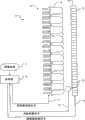
图1A示出了包括调制器12的显示器10,包括可单独控制的光源16的阵列的照明器14从背后照明调制器12。调制器12包括多个像素元件13。可以单独控制像素元件13以便选择性地调制来自光源16的光。在示出的实施例中,光源16包括发光二极管(LED)。在下面的描述中,光源16被称为LED 16,并且调制器12被称为LCD面板。可使用其它适合的光源以取代LED 16。可使用其它适合的调制器以取代LCD面板12。可如例如在国际申请No.PCT/CA03/00350中所描述的单独控制每个LED 16的光输出和每个像素元件13的调制。FIG. 1A shows a display 10 comprising a
控制器19产生照明器控制信号17和调制器控制信号18以便显示所希望的图像。所希望的图像可由图像数据11指定,图像数据11直接或间接地指定每个像素的亮度(luminance)值(以及色值,如果图像是彩色图像)。图像数据11可具有任何适合的格式,并且可以使用任何适合的色模型指定亮度和色值。例如,图像数据11可以指定:A
每个像素的红、绿和蓝(RGB)色值;Red, green, and blue (RGB) color values for each pixel;
YIQ值,其中每个像素由被称为亮度的值(Y)和被称为色度的一对值(I,Q)表示;YIQ values, where each pixel is represented by a value (Y) called luminance and a pair of values (I, Q) called chrominance;
CMY或CMYK值;CMY or CMYK values;
YUV值;YUV value;
YCbCr值;YCbCr value;
HSV值;或HSV value; or
HSL值。HSL value.
图像数据11可以具有任何适合的图像数据格式。
在某些实施例中,光源16可以包括不同颜色的LED,或可以包括三色LED,每个三色LED包括全部封装在单个壳体内的红、绿和蓝LED。在这种实施例中,照明器控制信号17可以使得适合的驱动电路分别控制不同颜色的LED 16的明度,并且在特定的颜色中,分别控制位于不同位置的LED 16的明度。这允许照明器14在调制器12上投射在调制器12上的不同位置处具有不同颜色混合的光图案,或以时间交织(time interleaved)的方式在调制器12上顺序地投射红色、绿色和蓝色图案。In some embodiments,
在图1A的实施例中,控制器19接收图像数据11,并且基于图像数据11产生控制LED 16的强度的照明器控制信号17。控制器19还产生控制每个像素元件13所传递(pass)的光的量的调制器控制信号18。在某些实施例中,调制器控制信号18还可以控制每个像素元件13所传递的光的光谱。In the embodiment of FIG. 1A , a
例如,可基于LED 16的强度和散布(spread)函数产生调制器控制信号18。LED 16的散布函数代表入射到调制器12上的来自LED16的光的图案。可以在光场模拟中使用LED 16的强度和散布函数,以便获得由照明器14在调制器12上创建的预期照明图案。然后可以使用光场模拟确定为了显示所希望的图像而应当由每个像素元件13传递的光的量。在所希望的图像是彩色图像的情况下,还可以使用光场模拟确定为了显示所希望的图像而应当由每个像素元件13应用的颜色过滤(如果有的话)的量。For example,
在图1A的实施例中,光检测器20检测由LED 16发出的光,并且向控制器19提供光检测器信号21。光检测器信号21可以指示在光检测器20处检测到的由LED 16发出的光的强度。光检测器20可以附加地或可替换地包括分光计,在该情况下,光检测器信号21可以指示由LED 16发出的光的光谱特性。In the embodiment of FIG. 1A ,
在图1A的实施例中,提供了可以移动到不同位置以便捕获来自不同LED 16的向前发射的光的单个光检测器20。在可替换方案中,可以提供多个光检测器,或可以提供适合的光学系统以将来自LED16的光导向光检测器20。例如,图1B示出了类似于图1A的实施例,其中平面光波导22收集由LED 16发出的向前发射的光的一小部分,并且将该光传送到光检测器20。图1B的实施例还包括如例如国际申请No.PCT/CA03/00350中所描述的、用于提高每个LED 16照明调制器12的均匀性的反射壁通道的栅格23。In the embodiment of FIG. 1A , a
图1A和1B本质上是示意性的。调制器12和光源16的组件可被布置成任何适合的二维布置,而不必如图所示那样布置。Figures 1A and 1B are schematic in nature. The assembly of
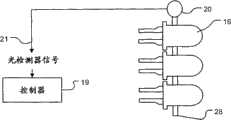
图2A-C示出了光检测器20检测由LED 16发出的杂散光的实施例。在图2A的实施例中,光波导24将来自LED 16的杂散光传送到光检测器20。仅有由每个LED 16发出的光的一小部分被波导24捕获。只要波导24和相应LED 16之间的耦合不改变,由波导24捕获的由LED 16发出的光的比例保持恒定。一个光检测器20或数个光检测器20可被定位在方便的位置,诸如定位在照明器14的边缘处。2A-C illustrate an embodiment in which
在图2B的实施例中,用平面光波导26取代单个光波导24。用于LED 16的电源线穿过波导26中的孔。一个或多个光检测器20定位在光波导26的边缘处。由任何LED 16在向后方向上发射的光被俘获到光波导26内,并且被光检测器20检测。在图2C的实施例中,平面光波导28在侧向方向上收集由LED 16发出的光,并且将光传送到一个或多个光检测器20。In the embodiment of FIG. 2B , the single
图3A示出了由附近的LED 16收集来自一个LED 16的杂散光的实施例。当来自响应于照明器控制信号17发光的一个LED 16的杂散光入射到不发光的LED 16上时,在该不发光LED 16中感应出电势。Figure 3A shows an embodiment where stray light from one
每个LED 16可连接到电路32。图3中仅示出了连接到不发光LED 16的电路32。由入射光在不发光LED 16上感应出的电势可以导致与入射到其上的光的强度成比例的电流在连接的电路32中流动。可由电流检测器33测量在电路32中流动的电流,电流检测器33给控制器19提供反馈信号31。控制器19可以基于来自其它LED 16的反馈信号31确定该一个LED 16的光输出。可替换地,电路32可连接到控制器19,并且控制器19可以包括用于测量由不发光LED 16产生的电流的一个或多个内置的电流检测器。在这些实施例中,控制器19可以基于电流测量确定该一个LED 16的光输出。可以在仅有一个LED 16发出入射到对其进行电流测量的不发光LED 16上的光时,或在已知的一组两个或更多个LED 16发光时,进行这种电流测量,从而可以单独地确定每个发光LED 16的贡献。每个发光LED 16的贡献可例如使用与该发光LED 16具有已知几何关系的多个不发光LED 16感测来自该发光LED 16的光,通过三角测量被单独确定。在图3A的实施例中不需要独立的光检测器20。Each
图3B示出了这样的实施例,其中提供了开关34以用于将LED 16选择性地连接到驱动电路35或测量电路36。可由控制器19借助开关控制线37在驱动位置和测量位置之间操作开关34。当开关34位于驱动位置时,由驱动电路35响应来自控制器19的控制信号38驱动LED16发光。测量电路36可以给LED 16提供反偏压,并且可被配置成使得由LED 16吸取的电流随入射到LED 16上的光的量而变化。当开关34处于测量位置时,可由测量电路36测量流过LED 16的电流,测量电路36给控制器提供表示入射到LED 16上的光的测量信号39。FIG. 3B shows an embodiment in which a
图4是示出根据本发明的一个实施例的用于校准显示器的方法40的流程图。可由诸如例如根据图1A-B,2A-C或3A-B的实施例中的任一个的显示器的被多个可单独控制的光源从背后照明的显示器的控制器执行方法40。方法40还可以应用于包括多个可单独控制的光源的其它类型的显示器。FIG. 4 is a flowchart illustrating a
在块41,控制器使得光源中的此处被称为受测试源的一个光源发光。受测试源可在显示图像期间或响应校准照明器控制信号发光。At
在某些情况下,控制器可以仅使得受测试源发光。在这些情况下,可由发出的光入射到其上的光检测器检测发出的光,或可使用任何适合的光学系统收集发出的光并将其提供给光检测器。可替换地,在光源包括LED的实施例中,可由相邻的LED检测发出的光。In some cases, the controller may only illuminate the source under test. In these cases, the emitted light may be detected by a photodetector upon which the emitted light is incident, or any suitable optical system may be used to collect the emitted light and provide it to the photodetector. Alternatively, in embodiments where the light source comprises LEDs, emitted light may be detected by adjacent LEDs.
在其它情况下,控制器可以使得受测试源之外的一个或多个光源发光。在这些情况下,可由被定位成使得仅有来自受测试源的光入射到其上的光检测器检测由受测试源发出的光,或可由被配置为仅收集由受测试源发出的光的光学系统收集由受测试源发出的光,并且将其提供给光检测器。In other cases, the controller may illuminate one or more light sources other than the source under test. In these cases, the light emitted by the source under test may be detected by a photodetector positioned such that only light from the source under test is incident thereon, or may be detected by a light detector configured to collect only light emitted by the source under test. An optical system collects the light emitted by the source under test and provides it to a light detector.
在块42,控制器接收收集光信号。收集光信号可以包括从一个或多个光检测器接收的一个或多个光检测器信号。可替换地或附加地,收集光信号可以包括从LED接收的一个或多个反馈信号。收集光信号可以指示从受测试源发出的光的强度。在某些实施例中,收集光信号还指示从受测试源发出的光的色温。At
收集光信号可以表示在校准周期(cycle)期间收集的光,在校准周期中向受测试源提供校准照明器控制信号。可替换地,收集光信号可以表示在显示器显示图像时收集的光,在显示器显示图像时向受测试源提供由图像数据确定的照明器控制信号。The collected light signal may represent light collected during a calibration cycle in which a calibration illuminator control signal is provided to the source under test. Alternatively, the collected light signal may represent light collected while the display is displaying an image, at which time an illuminator control signal determined from the image data is provided to the source under test.
在块44,控制器确定由收集光信号表示的收集的光的预期光特性。确定预期光特性可以例如包括查找存储的受测试源的参考值。预期光特性可以例如包括对于给定的照明器控制信号所预期的强度水平和/或光谱特性。存储值可例如被存储在控制器可访问的存储器内。At
在块46,控制器将收集光信号与预期光特性进行比较。如果收集光信号指示由受测试源发出的光具有预期特性(块46,“是”输出),则不需要校正。然后,方法40可以返回块41,以便校准其它光源,或如果已经校准了所有光源则可以结束。At
如果收集光信号指示由受测试源发出的光不具有预期特性(块46,“否”输出),则可能需要校正。然后,方法40进入块48。If the collected light signal indicates that the light emitted by the source under test does not have the expected characteristics (block 46, "No" output), then correction may be required.
在块48,控制器基于块46的比较结果确定将应用的校正。例如,如果比较指示由受测试源发出的光的强度不同于预期强度,控制器可以确定针对受测试源的强度校正,并且将该强度校正存储在位于该控制器可访问的存储器中的数据结构中。类似地,如果比较结果指示受测试源的色温不同于预期色温,控制器可以确定针对受测试源的颜色校正,并且将该颜色校正存储在位于该控制器可访问的存储器中的数据结构中。At
如果比较指示由受测试源发出的光的强度小于预期强度,强度校正可包括例如调整照明器控制信号以使得给受测试源提供增加的电流的指示。可替换地或附加地,强度校正可以包括调整照明器控制信号以使得给受测试源提供增加的电压的指示。If the comparison indicates that the intensity of light emitted by the source under test is less than expected, intensity correction may include, for example, adjusting the illuminator control signal so that an indication of increased current is provided to the source under test. Alternatively or additionally, the intensity correction may comprise adjusting the illuminator control signal such that an indication of an increased voltage is provided to the source under test.
在某些实施例中,向光源提供电功率脉冲,而不是提供连续的供电。对于每个光源,脉冲的占空比确定由该光源发出的光的被察觉强度。此处术语“占空比”指的是给光源提供电功率的时间的比例。图5A示出了用于给光源提供电功率脉冲的示例照明器控制信号,其中光源在50%的时间中以最大强度发光,这对应于50%的占空比。脉冲的时间标度为使得人眼察觉到光源以50%的强度连续发光。在这些实施例中,强度校正可以包括调整照明器控制信号以使得给受测试源提供的电脉冲具有增加的或减小的占空比的指示。图5B示出了针对如下情况的这种调整后的照明器控制信号的例子,即其中受测试源被确定为具有33%的强度降低,并且照明器控制信号被调整以将脉冲的占空比增加33%,得到调整后的66.5%的占空比。In some embodiments, pulses of electrical power are provided to the light source rather than a continuous supply of power. For each light source, the duty cycle of the pulses determines the perceived intensity of the light emitted by that light source. Herein the term "duty cycle" refers to the proportion of time that electric power is supplied to a light source. Fig. 5A shows an example illuminator control signal for providing pulses of electrical power to a light source, wherein the light source emits light at
取代或除了对于受测试源调整照明器控制信号的指示之外,强度校正可以包括对于受测试源周围的区域内的其它光源调整照明器控制信号的指示。图6示出了包括矩形阵列的一部分的光源的示例布置。图6所示的光源的列和行分别用参考字母a-e和数字1-5标记。在图6的实施例中,如果光源c3的强度小于预期强度,强度校正可以包括例如增加提供给光源c2,c4,b3和d3的电流、电压和/或电功率的占空比的指示。强度校正还可以包括对于光源b2,b4,d2和d4或对于距离光源c3更远的光源调整照明器控制信号的指示。Instead of or in addition to adjusting the indication of the illuminator control signal for the source under test, the intensity correction may include adjusting the indication of the illuminator control signal for other light sources in the area around the source under test. Figure 6 shows an example arrangement of light sources comprising part of a rectangular array. The columns and rows of light sources shown in Figure 6 are labeled with reference letters a-e and numbers 1-5, respectively. In the embodiment of FIG. 6, if the intensity of light source c3 is less than expected, the intensity correction may include, for example, an indication to increase the duty cycle of the current, voltage and/or electrical power supplied to light sources c2, c4, b3 and d3. The intensity correction may also include an indication to adjust the illuminator control signal for light sources b2, b4, d2 and d4 or for light sources further away from light source c3.
在某些实施例中,强度校正包括以不均匀的方式对于受测试源周围的区域内的光源调整照明器控制信号的指示。例如,可以根据加权函数不均匀地调整周围光源的照明器控制信号。加权函数可以例如基于周围光源的强度,或周围光源的强度与受测试源的预期强度的相似性。加权函数中可以包括的一个因素是来自受测试源的光的空间分布。可以基于以该空间分布对测量的强度的加权,产生强度校正。空间分布可以是例如用于显示器的图像处理的点散布函数。In some embodiments, the intensity correction includes adjusting the indication of the illuminator control signal in a non-uniform manner for light sources in an area surrounding the source under test. For example, illuminator control signals for ambient light sources may be non-uniformly adjusted according to a weighting function. The weighting function may eg be based on the intensity of the surrounding light sources, or the similarity of the intensity of the surrounding light sources to the expected intensity of the source under test. One factor that can be included in the weighting function is the spatial distribution of light from the source under test. Intensity corrections can be generated based on weighting the measured intensities with this spatial distribution. The spatial distribution may be, for example, a point spread function for image processing of a display.
例如,在图6的实施例中,如果光源c3的强度小于预期强度,强度校正可以包括例如这样的指示,即增加给在光源c3的预定邻域(proximity)内的具有最高强度的一个或多个光源提供的电流、电压和/或电功率的脉冲宽度。例如,如果光源a1与光源c3周围的其它光源相比具有相对高的强度,强度校正可以包括这样的指示,即增加给光源a1提供的电流、电压和/或电功率的脉冲宽度,而不调整更靠近光源c3的光源的照明器控制信号。可替换地,强度校正可以包括例如这样的指示,即增加给在光源c3的预定邻域内的、具有最接近光源c3的预期强度的强度值的一个或多个光源提供的电流、电压和/或电功率的脉冲宽度。For example, in the embodiment of FIG. 6, if the intensity of light source c3 is less than the expected intensity, the intensity correction may include, for example, an indication to add to one or more sources with the highest intensity within a predetermined proximity of light source c3. The pulse width of current, voltage and/or electrical power supplied by a light source. For example, if light source a1 has a relatively high intensity compared to other light sources surrounding light source c3, the intensity correction may include an indication to increase the current, voltage, and/or pulse width of electrical power provided to light source a1 without adjusting more. Illuminator control signal for light sources close to light source c3. Alternatively, the intensity correction may include, for example, an indication to increase the current, voltage and/or Pulse width of electrical power.
在光源包括均匀间隔的LED的阵列的实施例中,强度校正可以包括这样的指示,即调整控制信号,以使得对于距连接到测量电路的不发光LED相同距离的源,该不发光LED感测到相同的强度。距该不发光LED相同距离的多个源可被校准以均匀地发光。然后,另一个不发光LED可检测这些校准后的LED的强度,并且使用检测到的强度作为参考强度。该其它不发光LED可被用于检测距其的距离与校准后的LED相同的其它源的强度,并且基于参考强度校准这些其它源。可以在整个LED阵列上执行该处理,以便使得LED均匀发光,而不用校准作为检测器的每个LED的灵敏度。一旦LED被校准以均匀发光,可以使用类似处理校准作为检测器的每个LED的灵敏度。因此随后可以使用作为检测器的LED的灵敏度,而不用重复上述的处理。In embodiments where the light source comprises an array of evenly spaced LEDs, the intensity correction may include an indication that the control signal is adjusted so that for a source at the same distance from a non-emitting LED connected to the measurement circuit, the non-emitting LED senses to the same intensity. Multiple sources at the same distance from the non-emitting LED can be calibrated to emit light evenly. Then, another non-emitting LED can detect the intensity of these calibrated LEDs and use the detected intensity as a reference intensity. This other non-emitting LED can be used to detect the intensity of other sources at the same distance as the calibrated LED, and to calibrate these other sources based on the reference intensity. This process can be performed across the entire LED array in order to make the LEDs emit light evenly without calibrating the sensitivity of each LED as a detector. Once the LEDs are calibrated to emit light uniformly, a similar process can be used to calibrate the sensitivity of each LED as a detector. The sensitivity of the LED as detector can thus be used subsequently without repeating the above-mentioned process.
除了或取代强度校正之外,在块48,控制器可确定受测试源需要颜色校正。可例如通过提供照明器控制信号以驱动受测试源发出白光,测量发出的光的光谱,并且将测量的光谱与预期光谱进行比较,做出需要颜色校正的确定。预期频谱可以包括例如诸如由ITURecommendation BT.709规定的D65白点的预定的频谱。In addition to or instead of intensity correction, at
在光源包括彩色光源的实施例中,颜色校正可以包括这样的指示,即调整用于产生受测试源的照明器控制信号的色值,以便补偿与预期色温的任何偏离。可替换地或附加地,颜色校正可以包括这样的指示,即调整用于产生来自受测试源的光入射到其上的调制器部分的调制器控制信号的色值。例如可以通过用受测试源的测量的色温取代预期色温以计算受测试源的颜色校准的散布函数,确定调制器控制信号的这种调整。然后,可以在光场模拟中包括颜色校准的散布函数,从而调制器应用颜色过滤,以校正所显示的图像的观看者察觉到的色温。在使用RGB色值的实施例中,例如可以通过以红色、绿色和蓝色通道的最小值归一化测量的光谱,确定对色值的调整。In embodiments where the light source comprises a colored light source, the color correction may include an instruction to adjust the color values used to generate the illuminator control signal for the source under test to compensate for any deviation from the expected color temperature. Alternatively or additionally, color correction may comprise an indication to adjust the color value of the modulator control signal used to generate the modulator portion on which the light from the source under test is incident. Such an adjustment of the modulator control signal may be determined, for example, by substituting the measured color temperature of the source under test for the expected color temperature to calculate a spread function of the color calibration of the source under test. A color calibrated spread function can then be included in the light field simulation so that the modulator applies color filtering to correct the color temperature perceived by a viewer of the displayed image. In embodiments using RGB color values, adjustments to the color values may be determined, for example, by normalizing the measured spectrum with the minimum values of the red, green, and blue channels.
在块48确定了校正之后,可以在块50应用校正。应用校正可以包括如校正所指示的那样调整照明器和/或调制器控制信号。还可以在块50存储校正。存储校正可以包括在控制器可以访问的电子存储器中存储校正。控制器可在校正被确定时应用校正,或可以存储多个校正,并且在随后的时间应用存储的校正。After the correction is determined at
可以对于多个光源中的每一个顺序地执行方法40。例如,当驱动显示器以显示由图像数据指定的一系列帧时,可在每一帧期间对于光源中的一个光源执行方法40,直到校准了每个光源为止。可替换地,可对于多于一个的光源同时执行方法40。例如,可以在块42接收表示从光源的一个子集或全部光源收集的光的多个收集光信号。在对于光源的一个子集接收到收集光信号的实施例中,可对于光源的所有其它子集重复方法40。
可定期地自动执行方法40,或可以响应由控制器接收的校准命令执行方法40。可替换地或附加地,可以连续地或定期地测量来自显示器的数据,并且可响应于测量数据超出阈值来执行方法40。测量数据可以包括例如热数据。
如本领域的技术人员鉴于前面的公开将会明了的,在本发明的实现中可以有许多变化和修改,而不脱离本发明的范围。例如:As will be apparent to those skilled in the art in view of the foregoing disclosure, many changes and modifications are possible in the practice of the invention without departing from the scope of the invention. For example:
取代在提供照明器和调制器控制信号的控制器处接收收集光信号,可以提供分开的校准控制器,以接收收集光信号并且确定将被应用的校正。Instead of receiving the collected light signal at the controller providing illuminator and modulator control signals, a separate calibration controller may be provided to receive the collected light signal and determine the correction to be applied.
如本领域的技术人员鉴于前面的公开将会明了的,在本发明的实现中可以有许多变化和修改,而不脱离本发明的范围。因此,本发明的范围应根据下面的权利要求所定义的实质内容解释。As will be apparent to those skilled in the art in view of the foregoing disclosure, many changes and modifications are possible in the practice of the invention without departing from the scope of the invention. Accordingly, the scope of the present invention should be construed in light of the substance defined by the following claims.
Claims (30)
Applications Claiming Priority (3)
| Application Number | Priority Date | Filing Date | Title |
|---|---|---|---|
| US89909807P | 2007-02-01 | 2007-02-01 | |
| US60/899,098 | 2007-02-01 | ||
| PCT/CA2008/000221WO2008092276A1 (en) | 2007-02-01 | 2008-02-01 | Calibration of displays having spatially-variable backlight |
Publications (2)
| Publication Number | Publication Date |
|---|---|
| CN101632113A CN101632113A (en) | 2010-01-20 |
| CN101632113Btrue CN101632113B (en) | 2012-10-03 |
Family
ID=39673618
Family Applications (1)
| Application Number | Title | Priority Date | Filing Date |
|---|---|---|---|
| CN2008800082080AActiveCN101632113B (en) | 2007-02-01 | 2008-02-01 | Calibration of displays having spatially-variable backlight |
Country Status (8)
| Country | Link |
|---|---|
| US (1) | US8471807B2 (en) |
| EP (2) | EP2118880A4 (en) |
| JP (1) | JP5002656B2 (en) |
| KR (1) | KR101126094B1 (en) |
| CN (1) | CN101632113B (en) |
| ES (1) | ES2893327T3 (en) |
| MX (1) | MX2009008192A (en) |
| WO (1) | WO2008092276A1 (en) |
Families Citing this family (31)
| Publication number | Priority date | Publication date | Assignee | Title |
|---|---|---|---|---|
| US8442316B2 (en)* | 2007-01-05 | 2013-05-14 | Geo Semiconductor Inc. | System and method for improving color and brightness uniformity of backlit LCD displays |
| WO2010039440A1 (en) | 2008-09-30 | 2010-04-08 | Dolby Laboratories Licensing Corporation | Systems and methods for applying adaptive gamma in image processing for high brightness and high dynamic range displays |
| GB2465195A (en)* | 2008-11-10 | 2010-05-12 | Iti Scotland Ltd | Controlling the brightness of an LCD backlight comprising a plurality of LEDs |
| CN101749569A (en)* | 2008-12-02 | 2010-06-23 | 鸿富锦精密工业(深圳)有限公司 | Light emitting module |
| US20120038922A1 (en)* | 2009-02-19 | 2012-02-16 | 3D Perception As | Method and device for measuring at least one of light intensity and colour in at least one modulated image |
| WO2010120582A2 (en) | 2009-04-15 | 2010-10-21 | Dolby Laboratories Licensing Corporation | Thin displays having spatially variable backlights |
| KR101409162B1 (en) | 2009-06-02 | 2014-06-19 | 돌비 레버러토리즈 라이쎈싱 코오포레이션 | Multi-die led package and backlight unit using the same |
| US8791932B2 (en)* | 2009-06-18 | 2014-07-29 | Sharp Kabushiki Kaisha | Display device and display control method |
| WO2011028335A1 (en) | 2009-09-02 | 2011-03-10 | Dolby Laboratories Licensing Corporation | Compensation for sub-par lighting in displays |
| US9341887B2 (en) | 2009-09-11 | 2016-05-17 | Dolby Laboratories Licensing Corporation | Displays with a backlight incorporating reflecting layer |
| CN102598675B (en) | 2009-10-28 | 2014-12-03 | 杜比实验室特许公司 | Stereoscopic dual modulator display device using full color anaglyph |
| US9681112B2 (en)* | 2009-11-05 | 2017-06-13 | Lg Electronics Inc. | Image display apparatus and method for controlling the image display apparatus |
| KR101267304B1 (en) | 2010-02-22 | 2013-05-27 | 돌비 레버러토리즈 라이쎈싱 코오포레이션 | Methods and systems for reducing power consumption in dual modulation displays |
| EP3051530B1 (en) | 2010-06-21 | 2022-08-31 | Dolby Laboratories Licensing Corporation | Displaying images on local-dimming displays |
| US8717278B2 (en) | 2010-08-31 | 2014-05-06 | Dolby Laboratories Licensing Corporation | Method and apparatus for adjusting drive values for dual modulation displays |
| US9124881B2 (en)* | 2010-12-03 | 2015-09-01 | Fly's Eye Imaging LLC | Method of displaying an enhanced three-dimensional images |
| WO2012078262A1 (en) | 2010-12-06 | 2012-06-14 | Dolby Laboratories Licensing Corporation | Methods and apparatus for image adjustment for displays having 2d and 3d display modes |
| WO2012082825A2 (en) | 2010-12-17 | 2012-06-21 | Dolby Laboratories Licensing Corporation | Quantum dots for display panels |
| US8982038B2 (en)* | 2011-05-13 | 2015-03-17 | Samsung Display Co., Ltd. | Local dimming display architecture which accommodates irregular backlights |
| EP2766894A1 (en) | 2011-10-13 | 2014-08-20 | Dolby Laboratories Licensing Corporation | Methods and apparatus for backlighting dual modulation display devices |
| US9747866B2 (en)* | 2011-11-22 | 2017-08-29 | Dolby Laboratories Licensing Corporation | Optimizing light output profile for dual-modulation display performance |
| WO2013159812A1 (en)* | 2012-04-24 | 2013-10-31 | Hewlett-Packard Development Company, L.P. | Printing system and method of operation |
| KR101620309B1 (en)* | 2012-08-10 | 2016-05-12 | 돌비 레버러토리즈 라이쎈싱 코오포레이션 | A light source, a method for illuminating a diaplay panel in a display system, an apparatus and a computer-readable storage medium thereof |
| JP5800946B2 (en)* | 2013-05-10 | 2015-10-28 | キヤノン株式会社 | Image display apparatus and control method thereof |
| JP2015200734A (en)* | 2014-04-07 | 2015-11-12 | キヤノン株式会社 | Image display apparatus, image display apparatus control method, and program |
| US20170061894A1 (en)* | 2015-08-26 | 2017-03-02 | Canon Kabushiki Kaisha | Image display apparatus |
| CN108521826B (en)* | 2016-12-28 | 2020-04-28 | 三菱电机株式会社 | Light emitting unit, display device, and multi-display device |
| FR3101691B1 (en)* | 2019-10-04 | 2022-07-08 | Valeo Vision | METHOD FOR CONTROLLING A LIGHT DEVICE FOR THE EMISSION OF A PIXELIZED LIGHT BEAM |
| US12016097B2 (en)* | 2019-12-20 | 2024-06-18 | Lumileds Llc | Failure detection and correction for LED arrays |
| US11804187B2 (en)* | 2021-06-25 | 2023-10-31 | Apple Inc. | Displays with reduced color non-uniformity |
| JP2023112276A (en)* | 2022-02-01 | 2023-08-14 | セイコーエプソン株式会社 | Circuit device and display device |
Citations (5)
| Publication number | Priority date | Publication date | Assignee | Title |
|---|---|---|---|---|
| CN1643565A (en)* | 2002-03-13 | 2005-07-20 | 不列颠哥伦比亚大学 | High dynamic range display devices |
| US20060028156A1 (en)* | 2004-08-06 | 2006-02-09 | Paul Jungwirth | Lighting system including photonic emission and detection using light-emitting elements |
| US7052138B2 (en)* | 2002-12-05 | 2006-05-30 | Olympus Corporation | Display apparatus, light source device, and illumination unit |
| US20060238723A1 (en)* | 2005-04-22 | 2006-10-26 | El-Ghoroury Hussein S | Low profile, large screen display using a rear projection array system |
| CN101044541A (en)* | 2004-10-22 | 2007-09-26 | 阿德文泰克全球有限公司 | System and method for setting brightness uniformity in an active-matrix organic light-emitting diode (oled) flat-panel display |
Family Cites Families (140)
| Publication number | Priority date | Publication date | Assignee | Title |
|---|---|---|---|---|
| US4316196A (en)* | 1977-03-10 | 1982-02-16 | Bell & Howell Corporation | Illumination and light gate utilization methods and apparatus |
| US4170771A (en)* | 1978-03-28 | 1979-10-09 | The United States Of America As Represented By The Secretary Of The Army | Orthogonal active-passive array pair matrix display |
| US4229095A (en)* | 1979-01-29 | 1980-10-21 | Eastman Kodak Company | Electro-optical color imaging apparatus |
| US4364039A (en)* | 1980-07-25 | 1982-12-14 | Texas Instruments Incorporated | Stacked electro-optic display |
| US4441791A (en)* | 1980-09-02 | 1984-04-10 | Texas Instruments Incorporated | Deformable mirror light modulator |
| US4378568A (en)* | 1981-01-29 | 1983-03-29 | Eastman Kodak Company | Light valve imaging apparatus and method for providing gray scale |
| US4374397A (en)* | 1981-06-01 | 1983-02-15 | Eastman Kodak Company | Light valve devices and electronic imaging/scan apparatus with locationally-interlaced optical addressing |
| JPS5810481U (en)* | 1981-07-10 | 1983-01-22 | シャープ株式会社 | liquid crystal display device |
| FR2536563B1 (en)* | 1982-11-23 | 1985-07-26 | Ssih Equipment Sa | LIGHT EMITTING ELEMENT WITH DISCHARGE TUBE FOR MATRIX DISPLAY BOARD |
| NL8401605A (en)* | 1984-05-18 | 1985-12-16 | Optische Ind De Oude Delft Nv | LIGHT BOX FOR GIVING A BACKGROUND LIGHT WITH BRIGHTNESS VALUES ADAPTED TO THE BLACK OF A LIGHT BOX FOR VIEWING. |
| JPS6218593A (en)* | 1985-07-17 | 1987-01-27 | シャープ株式会社 | data processing equipment |
| US4868668A (en)* | 1986-08-21 | 1989-09-19 | Electrohome Limited | System and method for image adjustment in an optical projection system |
| ES2040258T3 (en)* | 1986-09-20 | 1993-10-16 | Thorn Emi Plc | DISPLAY DEVICE. |
| US4726663A (en)* | 1986-11-14 | 1988-02-23 | Tektronix, Inc. | Switchable color filter with enhanced transmissivity |
| US4801194A (en)* | 1987-09-23 | 1989-01-31 | Eastman Kodak Company | Multiplexed array exposing system having equi-angular scan exposure regions |
| US4933754A (en)* | 1987-11-03 | 1990-06-12 | Ciba-Geigy Corporation | Method and apparatus for producing modified photographic prints |
| US4987410A (en)* | 1988-01-25 | 1991-01-22 | Kaiser Aerospace & Electronics Corporation | Multiple image forming apparatus |
| JPH01200232A (en)* | 1988-02-04 | 1989-08-11 | Sharp Corp | Ferroelectric liquid crystal display device |
| GB8823490D0 (en)* | 1988-10-06 | 1988-11-16 | Emi Plc Thorn | Method & apparatus for projecting scanned two/threedimensional modulated light pattern originating from light source |
| US5247366A (en)* | 1989-08-02 | 1993-09-21 | I Sight Ltd. | Color wide dynamic range camera |
| JP2582644B2 (en)* | 1989-08-10 | 1997-02-19 | 富士写真フイルム株式会社 | Flat panel image display |
| US4954789A (en)* | 1989-09-28 | 1990-09-04 | Texas Instruments Incorporated | Spatial light modulator |
| US5075789A (en)* | 1990-04-05 | 1991-12-24 | Raychem Corporation | Displays having improved contrast |
| GB9008031D0 (en)* | 1990-04-09 | 1990-06-06 | Rank Brimar Ltd | Projection systems |
| GB9008032D0 (en) | 1990-04-09 | 1990-06-06 | Rank Brimar Ltd | Video display systems |
| FR2669744B1 (en)* | 1990-11-23 | 1994-03-25 | Thomson Csf | LIGHTING DEVICE AND APPLICATION TO A VISUALIZATION DEVICE. |
| FR2664712B1 (en)* | 1991-10-30 | 1994-04-15 | Thomson Csf | OPTICAL MODULATION DEVICE WITH DEFORMABLE CELLS. |
| US5724062A (en)* | 1992-08-05 | 1998-03-03 | Cree Research, Inc. | High resolution, high brightness light emitting diode display and method and producing the same |
| US5359345A (en)* | 1992-08-05 | 1994-10-25 | Cree Research, Inc. | Shuttered and cycled light emitting diode display and method of producing the same |
| GB2278480A (en)* | 1993-05-25 | 1994-11-30 | Sharp Kk | Optical apparatus |
| US5440197A (en)* | 1993-10-05 | 1995-08-08 | Tir Technologies, Inc. | Backlighting apparatus for uniformly illuminating a display panel |
| ATE203836T1 (en)* | 1993-10-05 | 2001-08-15 | Tir Technologies Inc | LIGHT SOURCE FOR BACKLIGHTING |
| US5748828A (en)* | 1993-11-10 | 1998-05-05 | Alliedsignal Inc. | Color separating backlight |
| JP3213462B2 (en)* | 1993-11-25 | 2001-10-02 | 三洋電機株式会社 | Liquid crystal display |
| US5717422A (en)* | 1994-01-25 | 1998-02-10 | Fergason; James L. | Variable intensity high contrast passive display |
| US5592193A (en)* | 1994-03-10 | 1997-01-07 | Chunghwa Picture Tubes, Ltd. | Backlighting arrangement for LCD display panel |
| WO1996004582A1 (en)* | 1994-08-04 | 1996-02-15 | Rank Brimar Limited | Display system |
| US5639158A (en)* | 1994-08-19 | 1997-06-17 | Nec Corporation | Led-array light source |
| US5572341A (en)* | 1994-10-25 | 1996-11-05 | Fergason; James L. | Electro-optical dithering system using birefringence for optical displays and method |
| US5715029A (en)* | 1994-10-25 | 1998-02-03 | Fergason; James L. | Optical dithering system using birefringence for optical displays and method |
| US6184969B1 (en) | 1994-10-25 | 2001-02-06 | James L. Fergason | Optical display system and method, active and passive dithering using birefringence, color image superpositioning and display enhancement |
| US5537256A (en)* | 1994-10-25 | 1996-07-16 | Fergason; James L. | Electronic dithering system using birefrigence for optical displays and method |
| US6243055B1 (en)* | 1994-10-25 | 2001-06-05 | James L. Fergason | Optical display system and method with optical shifting of pixel position including conversion of pixel layout to form delta to stripe pattern by time base multiplexing |
| US6560018B1 (en)* | 1994-10-27 | 2003-05-06 | Massachusetts Institute Of Technology | Illumination system for transmissive light valve displays |
| US5646702A (en)* | 1994-10-31 | 1997-07-08 | Honeywell Inc. | Field emitter liquid crystal display |
| US5658829A (en)* | 1995-02-21 | 1997-08-19 | Micron Technology, Inc. | Semiconductor processing method of forming an electrically conductive contact plug |
| JP3764504B2 (en)* | 1995-02-28 | 2006-04-12 | ソニー株式会社 | Liquid crystal display |
| US6111560A (en)* | 1995-04-18 | 2000-08-29 | Cambridge Display Technology Limited | Display with a light modulator and a light source |
| US5787030A (en)* | 1995-07-05 | 1998-07-28 | Sun Microsystems, Inc. | Correct and efficient sticky bit calculation for exact floating point divide/square root results |
| US6120839A (en)* | 1995-07-20 | 2000-09-19 | E Ink Corporation | Electro-osmotic displays and materials for making the same |
| US6120588A (en)* | 1996-07-19 | 2000-09-19 | E Ink Corporation | Electronically addressable microencapsulated ink and display thereof |
| US5809215A (en)* | 1996-04-18 | 1998-09-15 | Lexmark International, Inc. | Method of printing to inhibit intercolor bleeding |
| US5729242A (en)* | 1996-05-08 | 1998-03-17 | Hughes Electronics | Dual PDLC-projection head-up display |
| US6323989B1 (en)* | 1996-07-19 | 2001-11-27 | E Ink Corporation | Electrophoretic displays using nanoparticles |
| GB2317290B (en)* | 1996-09-11 | 2000-12-06 | Seos Displays Ltd | Image display apparatus |
| KR100261214B1 (en)* | 1997-02-27 | 2000-07-01 | 윤종용 | Histrogram equalization method and apparatus of a contrast expanding apparatus in image processing system |
| US5986628A (en)* | 1997-05-14 | 1999-11-16 | Planar Systems, Inc. | Field sequential color AMEL display |
| US5959777A (en)* | 1997-06-10 | 1999-09-28 | The University Of British Columbia | Passive high efficiency variable reflectivity image display device |
| US6215920B1 (en)* | 1997-06-10 | 2001-04-10 | The University Of British Columbia | Electrophoretic, high index and phase transition control of total internal reflection in high efficiency variable reflectivity image displays |
| US5815303A (en)* | 1997-06-26 | 1998-09-29 | Xerox Corporation | Fault tolerant projective display having redundant light modulators |
| US6300932B1 (en)* | 1997-08-28 | 2001-10-09 | E Ink Corporation | Electrophoretic displays with luminescent particles and materials for making the same |
| US6476783B2 (en)* | 1998-02-17 | 2002-11-05 | Sarnoff Corporation | Contrast enhancement for an electronic display device by using a black matrix and lens array on outer surface of display |
| AU3767899A (en)* | 1998-04-27 | 1999-11-16 | E-Ink Corporation | Shutter mode microencapsulated electrophoretic display |
| JP3280307B2 (en)* | 1998-05-11 | 2002-05-13 | インターナショナル・ビジネス・マシーンズ・コーポレーション | Liquid crystal display |
| US6243068B1 (en)* | 1998-05-29 | 2001-06-05 | Silicon Graphics, Inc. | Liquid crystal flat panel display with enhanced backlight brightness and specially selected light sources |
| JP3763378B2 (en) | 1998-07-21 | 2006-04-05 | シャープ株式会社 | Light guide film manufacturing method, light guide film manufactured by the manufacturing method, laminated film, and liquid crystal display device |
| EP1018718B1 (en)* | 1998-07-24 | 2005-09-14 | Seiko Epson Corporation | Display |
| GB9828287D0 (en) | 1998-12-23 | 1999-02-17 | Secr Defence Brit | Image display system |
| US6381372B1 (en)* | 1998-12-30 | 2002-04-30 | Xerox Corporation | Systems and methods for designing image processing filters using templates |
| US6831624B1 (en)* | 1999-01-15 | 2004-12-14 | Sharp Kabushiki Kaisha | Time sequentially scanned display |
| JP2000214827A (en) | 1999-01-21 | 2000-08-04 | Toray Ind Inc | Color liquid crystal display device in field sequential drive system |
| US6520646B2 (en)* | 1999-03-03 | 2003-02-18 | 3M Innovative Properties Company | Integrated front projection system with distortion correction and associated method |
| JP2000275595A (en) | 1999-03-25 | 2000-10-06 | Sharp Corp | Inspection method of liquid crystal display |
| US6439731B1 (en)* | 1999-04-05 | 2002-08-27 | Honeywell International, Inc. | Flat panel liquid crystal display |
| US6327072B1 (en)* | 1999-04-06 | 2001-12-04 | E Ink Corporation | Microcell electrophoretic displays |
| US6483643B1 (en)* | 1999-04-08 | 2002-11-19 | Larry Zuchowski | Controlled gain projection screen |
| US6144162A (en)* | 1999-04-28 | 2000-11-07 | Intel Corporation | Controlling polymer displays |
| US7071907B1 (en) | 1999-05-07 | 2006-07-04 | Candescent Technologies Corporation | Display with active contrast enhancement |
| US6631995B2 (en)* | 1999-09-02 | 2003-10-14 | Koninklijke Philips Electronics N.V. | Method of and device for generating an image having a desired brightness |
| JP2001100699A (en) | 1999-09-29 | 2001-04-13 | Canon Inc | Projection display device and its application system |
| JP2001100689A (en) | 1999-09-30 | 2001-04-13 | Canon Inc | Display device |
| US6054120A (en)* | 1999-10-08 | 2000-04-25 | Burgoyne; Bradley C. | Sunscreen applicator system |
| JP3688574B2 (en) | 1999-10-08 | 2005-08-31 | シャープ株式会社 | Liquid crystal display device and light source device |
| US6359662B1 (en) | 1999-11-05 | 2002-03-19 | Agilent Technologies, Inc. | Method and system for compensating for defects in a multi-light valve display system |
| US6414661B1 (en)* | 2000-02-22 | 2002-07-02 | Sarnoff Corporation | Method and apparatus for calibrating display devices and automatically compensating for loss in their efficiency over time |
| WO2001069584A1 (en) | 2000-03-14 | 2001-09-20 | Mitsubishi Denki Kabushiki Kaisha | Image display and image displaying method |
| DE60103524T2 (en) | 2000-03-15 | 2005-06-30 | Imax Corp., Mississauga | IMPROVEMENTS ON DMD IMAGE DISPLAY DEVICES |
| EP1136874A1 (en) | 2000-03-22 | 2001-09-26 | Hewlett-Packard Company, A Delaware Corporation | Projection screen |
| US6428189B1 (en)* | 2000-03-31 | 2002-08-06 | Relume Corporation | L.E.D. thermal management |
| TWI240241B (en)* | 2000-05-04 | 2005-09-21 | Koninkl Philips Electronics Nv | Assembly of a display device and an illumination system |
| US6621482B2 (en)* | 2000-05-15 | 2003-09-16 | Koninklijke Philips Electronics N.V. | Display arrangement with backlight means |
| US6608614B1 (en)* | 2000-06-22 | 2003-08-19 | Rockwell Collins, Inc. | Led-based LCD backlight with extended color space |
| ATE538594T1 (en) | 2000-07-03 | 2012-01-15 | Imax Corp | METHOD AND DEVICE FOR EXPANDING THE DYNAMIC RANGE OF A PROJECTION SYSTEM |
| JP2002091385A (en) | 2000-09-12 | 2002-03-27 | Matsushita Electric Ind Co Ltd | Lighting equipment |
| US6952195B2 (en) | 2000-09-12 | 2005-10-04 | Fuji Photo Film Co., Ltd. | Image display device |
| US6680834B2 (en)* | 2000-10-04 | 2004-01-20 | Honeywell International Inc. | Apparatus and method for controlling LED arrays |
| JP2002140338A (en) | 2000-10-31 | 2002-05-17 | Toshiba Corp | Dictionary construction support device and dictionary construction support method |
| US6644832B2 (en)* | 2000-12-25 | 2003-11-11 | Seiko Epson Corporation | Illumination device and manufacturing method therefor, display device, and electronic instrument |
| TW548964B (en) | 2001-01-24 | 2003-08-21 | Koninkl Philips Electronics Nv | Window brightness enhancement for LCD display |
| EP1390806B1 (en) | 2001-02-27 | 2010-08-25 | Dolby Laboratories Licensing Corporation | High dynamic range display devices |
| US20020159002A1 (en) | 2001-03-30 | 2002-10-31 | Koninklijke Philips Electronics N.V. | Direct backlighting for liquid crystal displays |
| US6590561B1 (en)* | 2001-05-26 | 2003-07-08 | Garmin Ltd. | Computer program, method, and device for controlling the brightness of a display |
| US6863401B2 (en) | 2001-06-30 | 2005-03-08 | Texas Instruments Incorporated | Illumination system |
| US7002533B2 (en)* | 2001-08-17 | 2006-02-21 | Michel Sayag | Dual-stage high-contrast electronic image display |
| US7175281B1 (en) | 2003-05-13 | 2007-02-13 | Lightmaster Systems, Inc. | Method and apparatus to increase the contrast ratio of the image produced by a LCoS based light engine |
| US7053881B2 (en) | 2001-11-02 | 2006-05-30 | Sharp Kabushiki Kaisha | Image display device and image display method |
| US7064740B2 (en) | 2001-11-09 | 2006-06-20 | Sharp Laboratories Of America, Inc. | Backlit display with improved dynamic range |
| CN100490007C (en)* | 2002-01-11 | 2009-05-20 | 反射公司 | Spatial Light Modulator with Charge Pump Pixel Cell |
| US6720942B2 (en)* | 2002-02-12 | 2004-04-13 | Eastman Kodak Company | Flat-panel light emitting pixel with luminance feedback |
| US6802612B2 (en) | 2002-03-15 | 2004-10-12 | Hewlett-Packard Development Company, L.P. | Configurations for color displays by the use of lenticular optics |
| US6728023B1 (en)* | 2002-05-28 | 2004-04-27 | Silicon Light Machines | Optical device arrays with optimized image resolution |
| US6753661B2 (en) | 2002-06-17 | 2004-06-22 | Koninklijke Philips Electronics N.V. | LED-based white-light backlighting for electronic displays |
| NZ517713A (en) | 2002-06-25 | 2005-03-24 | Puredepth Ltd | Enhanced viewing experience of a display through localised dynamic control of background lighting level |
| US20040012551A1 (en) | 2002-07-16 | 2004-01-22 | Takatoshi Ishii | Adaptive overdrive and backlight control for TFT LCD pixel accelerator |
| KR100828531B1 (en) | 2002-07-26 | 2008-05-13 | 삼성전자주식회사 | Liquid crystal display |
| US6832037B2 (en) | 2002-08-09 | 2004-12-14 | Eastman Kodak Company | Waveguide and method of making same |
| US6817717B2 (en) | 2002-09-19 | 2004-11-16 | Hewlett-Packard Development Company, L.P. | Display system with low and high resolution modulators |
| DE10245892A1 (en) | 2002-09-30 | 2004-05-13 | Siemens Ag | Illumination device for backlighting an image display device |
| GB0228089D0 (en) | 2002-12-02 | 2003-01-08 | Seos Ltd | Dynamic range enhancement of image display apparatus |
| JP3498290B1 (en) | 2002-12-19 | 2004-02-16 | 俊二 岸村 | White LED lighting device |
| JP4417639B2 (en)* | 2003-02-28 | 2010-02-17 | 日東光学株式会社 | Versa Lighter |
| KR100852579B1 (en) | 2003-03-31 | 2008-08-14 | 샤프 가부시키가이샤 | Surface illumination device and liquid display device using the same |
| JP4016876B2 (en)* | 2003-04-23 | 2007-12-05 | セイコーエプソン株式会社 | projector |
| AU2004235139A1 (en)* | 2003-04-25 | 2004-11-11 | Visioneered Image Systems, Inc. | Led illumination source/display with individual led brightness monitoring capability and calibration method |
| US7289163B2 (en)* | 2003-04-28 | 2007-10-30 | Samsung Electronics Co., Ltd. | Method and apparatus for adjusting color edge center in color transient improvement |
| US7097495B2 (en) | 2003-07-14 | 2006-08-29 | Tribotek, Inc. | System and methods for connecting electrical components |
| US7052152B2 (en) | 2003-10-03 | 2006-05-30 | Philips Lumileds Lighting Company, Llc | LCD backlight using two-dimensional array LEDs |
| US20070024576A1 (en) | 2004-01-13 | 2007-02-01 | Hassan Paddy A | Correction arrangements for portable devices with oled displays |
| DK1745436T3 (en) | 2004-04-15 | 2012-09-10 | Dolby Lab Licensing Corp | Methods and systems for converting images from low dynamic range to high dynamic range |
| US7532192B2 (en)* | 2004-05-04 | 2009-05-12 | Sharp Laboratories Of America, Inc. | Liquid crystal display with filtered black point |
| DK1779362T3 (en) | 2004-07-27 | 2016-06-27 | Dolby Laboratories Licensing Corp | Quick image reproduction on screen dual modulator |
| US20060092183A1 (en)* | 2004-10-22 | 2006-05-04 | Amedeo Corporation | System and method for setting brightness uniformity in an active-matrix organic light-emitting diode (OLED) flat-panel display |
| JP2006209054A (en)* | 2004-12-28 | 2006-08-10 | Hitachi Ltd | LIGHTING DEVICE AND DISPLAY DEVICE USING THE SAME |
| US7404645B2 (en) | 2005-06-20 | 2008-07-29 | Digital Display Innovations, Llc | Image and light source modulation for a digital display system |
| AU2007212447B2 (en) | 2006-02-03 | 2013-02-21 | Imclone Llc | IGF-IR antagonists as adjuvants for treatment of prostate cancer |
| KR100790698B1 (en) | 2006-04-19 | 2008-01-02 | 삼성전기주식회사 | Backlight Unit for Liquid Crystal Display |
| KR101204861B1 (en) | 2006-07-28 | 2012-11-26 | 삼성디스플레이 주식회사 | Backlight unit and liquid crystal display comprising the same |
| KR100828366B1 (en) | 2006-08-01 | 2008-05-08 | 삼성전자주식회사 | LCD TV with Dimming Panel and its Control Method |
| KR20080058821A (en) | 2006-12-22 | 2008-06-26 | 삼성전자주식회사 | Backlight Unit and Liquid Crystal Display |
| KR20080058820A (en) | 2006-12-22 | 2008-06-26 | 삼성전자주식회사 | Display device and control method |
- 2008
- 2008-02-01EPEP08706352Apatent/EP2118880A4/ennot_activeCeased
- 2008-02-01WOPCT/CA2008/000221patent/WO2008092276A1/enactiveApplication Filing
- 2008-02-01MXMX2009008192Apatent/MX2009008192A/enactiveIP Right Grant
- 2008-02-01EPEP14179095.6Apatent/EP2860721B1/enactiveActive
- 2008-02-01JPJP2009547506Apatent/JP5002656B2/enactiveActive
- 2008-02-01ESES14179095Tpatent/ES2893327T3/enactiveActive
- 2008-02-01KRKR1020097018107Apatent/KR101126094B1/enactiveActive
- 2008-02-01CNCN2008800082080Apatent/CN101632113B/enactiveActive
- 2008-02-01USUS12/524,809patent/US8471807B2/enactiveActive
Patent Citations (5)
| Publication number | Priority date | Publication date | Assignee | Title |
|---|---|---|---|---|
| CN1643565A (en)* | 2002-03-13 | 2005-07-20 | 不列颠哥伦比亚大学 | High dynamic range display devices |
| US7052138B2 (en)* | 2002-12-05 | 2006-05-30 | Olympus Corporation | Display apparatus, light source device, and illumination unit |
| US20060028156A1 (en)* | 2004-08-06 | 2006-02-09 | Paul Jungwirth | Lighting system including photonic emission and detection using light-emitting elements |
| CN101044541A (en)* | 2004-10-22 | 2007-09-26 | 阿德文泰克全球有限公司 | System and method for setting brightness uniformity in an active-matrix organic light-emitting diode (oled) flat-panel display |
| US20060238723A1 (en)* | 2005-04-22 | 2006-10-26 | El-Ghoroury Hussein S | Low profile, large screen display using a rear projection array system |
Also Published As
| Publication number | Publication date |
|---|---|
| JP5002656B2 (en) | 2012-08-15 |
| EP2118880A4 (en) | 2010-08-25 |
| EP2860721B1 (en) | 2021-09-01 |
| KR101126094B1 (en) | 2012-03-21 |
| US20100002026A1 (en) | 2010-01-07 |
| KR20090104913A (en) | 2009-10-06 |
| EP2860721A3 (en) | 2015-07-29 |
| MX2009008192A (en) | 2009-08-12 |
| EP2118880A1 (en) | 2009-11-18 |
| JP2010518419A (en) | 2010-05-27 |
| CN101632113A (en) | 2010-01-20 |
| EP2860721A2 (en) | 2015-04-15 |
| WO2008092276A1 (en) | 2008-08-07 |
| ES2893327T3 (en) | 2022-02-08 |
| US8471807B2 (en) | 2013-06-25 |
Similar Documents
| Publication | Publication Date | Title |
|---|---|---|
| CN101632113B (en) | Calibration of displays having spatially-variable backlight | |
| RU2419888C1 (en) | Backlight device, method of controlling backlight and liquid-crystal display device | |
| US10219342B2 (en) | Light source device and control method of light source device | |
| EP2168404B1 (en) | Systems and methods for calibrating solid state lighting panels using combined light output measurements | |
| JP4785931B2 (en) | System and method for calibrating a solid state lighting panel | |
| EP2082620B1 (en) | Method and driver for determining drive values for driving a lighting device | |
| US7557518B2 (en) | Solid-state, color-balanced backlight with wide illumination range | |
| KR20060012276A (en) | LED lighting source / display and calibration method with individual LED brightness monitoring | |
| US20080252664A1 (en) | Device and Method for Driving Light-Emitting Diodes | |
| US20080088244A1 (en) | Variable Color Illumination Apparatus | |
| US20090278789A1 (en) | Scanning backlight color control | |
| US9618789B2 (en) | Planar lighting apparatus and liquid crystal display apparatus | |
| JP2005513724A (en) | Color control for LED-based light emitters | |
| CN106169283B (en) | LED display device and image display device | |
| JP6234041B2 (en) | Image display apparatus and control method thereof | |
| US20150116388A1 (en) | Display apparatus and control method thereof | |
| JP2019113653A (en) | Liquid crystal display device | |
| JP2008251460A (en) | Backlight device, backlight control method, and liquid crystal display | |
| US20080012820A1 (en) | System and method for achieving desired operation illumination condition for light emitters | |
| KR100831871B1 (en) | LED backlight control circuit | |
| JP4715244B2 (en) | Projection device | |
| JP2020187199A (en) | Liquid crystal display device |
Legal Events
| Date | Code | Title | Description |
|---|---|---|---|
| C06 | Publication | ||
| PB01 | Publication | ||
| C10 | Entry into substantive examination | ||
| SE01 | Entry into force of request for substantive examination | ||
| C14 | Grant of patent or utility model | ||
| GR01 | Patent grant |