CN101630797B - Wireless remote control socket assembly - Google Patents
Wireless remote control socket assemblyDownload PDFInfo
- Publication number
- CN101630797B CN101630797BCN2009100421743ACN200910042174ACN101630797BCN 101630797 BCN101630797 BCN 101630797BCN 2009100421743 ACN2009100421743 ACN 2009100421743ACN 200910042174 ACN200910042174 ACN 200910042174ACN 101630797 BCN101630797 BCN 101630797B
- Authority
- CN
- China
- Prior art keywords
- module
- control
- wireless remote
- remote control
- power
- Prior art date
- Legal status (The legal status is an assumption and is not a legal conclusion. Google has not performed a legal analysis and makes no representation as to the accuracy of the status listed.)
- Expired - Fee Related
Links
- 238000000034methodMethods0.000claimsdescription5
- 230000001105regulatory effectEffects0.000claimsdescription3
- 238000010586diagramMethods0.000description7
- 239000003990capacitorSubstances0.000description3
- 230000009286beneficial effectEffects0.000description1
- 230000004397blinkingEffects0.000description1
- 238000012790confirmationMethods0.000description1
- 239000013078crystalSubstances0.000description1
- 230000000694effectsEffects0.000description1
- 230000005611electricityEffects0.000description1
Images


Landscapes
- Selective Calling Equipment (AREA)
- Remote Monitoring And Control Of Power-Distribution Networks (AREA)
Abstract
Description
Translated fromChinese技术领域technical field
本发明涉及用电设备的取电装置,特别是一种能够利用无线控制信号进行遥控的插座组件。The invention relates to a power-taking device of electric equipment, in particular to a socket assembly capable of remote control by using wireless control signals.
背景技术Background technique
现有的插座大多是利用手动操作插座上的机械开关来实现对插口的通断控制,使用不方便,对所接的电器不能进行有效管理,随着家庭、办公室等场所中所使用的电器数量越来越多,当大量的电器通过这种插座取电时,上述缺点将会更加突出。为了使用方便,市面上出现了遥控型插座组件,可以通过红外线或者无线网络进行插口通断的控制,但这种遥控插座一般只能一对一控制,即一个遥控器控制一个插座,并不能进行集中管理。Most of the existing sockets use the mechanical switch on the manual operation socket to realize the on-off control of the socket, which is inconvenient to use and cannot effectively manage the connected electrical appliances. More and more, when a large amount of electrical equipment gets electricity by this socket, above-mentioned shortcoming will be more outstanding. For the convenience of use, remote control socket components have appeared on the market, which can control the socket on and off through infrared rays or wireless networks. centralized management.
发明内容Contents of the invention
为解决上述问题,本发明提供一种使用简单、能够进行集中管理的无线遥控插座组件。To solve the above problems, the present invention provides a wireless remote control socket assembly that is easy to use and capable of centralized management.
本发明为解决其问题所采用的技术方案是:The technical scheme that the present invention adopts for solving its problem is:
一种无线遥控插座组件,包括无线遥控器以及两个或两个以上受无线遥控器控制的插座,所述无线遥控器包括遥控器控制芯片以及分别与遥控器控制芯片连接的发射模块、按键模块、显示模块、电源模块,所述插座包括市电输入接口、取电端和取电端通断控制器,所述取电端通断控制器包括:A wireless remote control socket assembly, including a wireless remote control and two or more sockets controlled by the wireless remote control, the wireless remote control includes a remote control control chip, a transmitting module connected to the remote control control chip, and a key module , a display module, and a power module, the socket includes a mains input interface, a power-taking terminal, and an on-off controller for the power-taking terminal, and the on-off controller for the power-taking terminal includes:
接收模块,接收无线遥控器发射的无线信号,处理后得到控制信号;The receiving module receives the wireless signal transmitted by the wireless remote controller, and obtains the control signal after processing;
控制模块,处理接收模块送入的控制信号,生成N路驱动信号,其中N为1,2,3,……,n;The control module processes the control signal sent by the receiving module, and generates N driving signals, where N is 1, 2, 3, ..., n;
学习按键,与控制模块连接,作为取电端通断控制器是否学习无线遥控器的遥控编码的选择控制端;The learning button is connected with the control module and serves as the selection control terminal for whether the on-off controller of the power-taking terminal learns the remote control code of the wireless remote control;
存储模块,与控制模块通讯并存储学习的遥控编码;The storage module communicates with the control module and stores the learned remote control codes;
执行模块,接收控制模块发出的N路驱动信号,控制取电端的N个插口的通断,其中N为1,2,3,……,n;The execution module receives N-channel drive signals sent by the control module, and controls the on-off of N sockets at the power-taking terminal, where N is 1, 2, 3, ..., n;
电源单元,将输入的交流电转换成稳压直流电,为取电端通断控制器提供工作电源。The power supply unit converts the input AC power into regulated DC power to provide working power for the on-off controller at the power-taking end.
优选的是,所述遥控器控制芯片为包含有LCD显示驱动的控制芯片,所述显示模块为LCD。Preferably, the remote controller control chip is a control chip including an LCD display driver, and the display module is an LCD.
优选的是,所述取电端通断控制器的控制模块为单片机。Preferably, the control module of the power-taking terminal on-off controller is a single-chip microcomputer.
优选的是,所述市电输入接口后端依次串接有过流保险和防雷模块。Preferably, overcurrent insurance and lightning protection modules are sequentially connected in series at the rear end of the mains input interface.
本发明的有益效果是:本发明通过设置能够简单方便地对插座进行定时通断控制和手动通断控制,从而实现对插座所接电器的有效管理;由于无线遥控器可以一次控制多个插座,每个插座上也可以设置多个受控插口,因此本发明能够对多个电器的集中控制,此外,每个插座通过学习不同的遥控编码进行区分识别,能够避免控制混乱的情况。The beneficial effects of the present invention are: the present invention can simply and conveniently perform timing on-off control and manual on-off control on the socket by setting, thereby realizing effective management of electrical appliances connected to the socket; since the wireless remote controller can control multiple sockets at one time, Multiple controlled sockets can also be set on each socket, so the present invention can centrally control multiple electrical appliances. In addition, each socket can distinguish and identify by learning different remote control codes, which can avoid control confusion.
过流保险和防雷模块能够给插座提供更好的保护,使得本发明具有更高的可靠性。The overcurrent insurance and lightning protection module can provide better protection for the socket, so that the present invention has higher reliability.
附图说明Description of drawings
下面结合附图和实施例对本发明作进一步说明:Below in conjunction with accompanying drawing and embodiment the present invention will be further described:
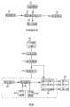
图1为本发明的无线遥控器和插座的硬件框图;Fig. 1 is the hardware block diagram of wireless remote controller and socket of the present invention;
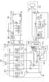
图2为无线遥控器的电路原理图;Fig. 2 is a schematic circuit diagram of a wireless remote controller;
图3为插座的电路原理图;Fig. 3 is the circuit principle diagram of socket;
图4为无线遥控器一种实施例的外观示意图;FIG. 4 is a schematic diagram of the appearance of an embodiment of a wireless remote controller;
图5为无线遥控器一种实施例的操作框图。Fig. 5 is an operation block diagram of an embodiment of a wireless remote controller.
具体实施方式Detailed ways
参照图1,本发明的无线遥控插座组件,包括无线遥控器以及受无线遥控器控制的插座,插座的数量设置为两个或者两个以上,实现一个无线遥控器对多路插座的控制,其中无线遥控器包括遥控器控制芯片101以及分别与遥控器控制芯片101连接的发射模块102、按键模块103、显示模块104、电源模块105,插座包括市电输入接口201、取电端202和取电端通断控制器,所述取电端通断控制器包括:Referring to Fig. 1, the wireless remote control socket assembly of the present invention includes a wireless remote control and a socket controlled by the wireless remote control, and the number of sockets is set to two or more to realize the control of multiple sockets by a wireless remote control, wherein The wireless remote control includes a remote
接收模块203,接收无线遥控器发射的无线信号,处理后得到控制信号;The
控制模块204,处理接收模块203送入的控制信号,生成N路驱动信号,其中N为1,2,3,……,n;The
学习按键205,与控制模块204连接,作为取电端通断控制器是否学习无线遥控器的遥控编码的选择控制端;The learning button 205 is connected with the
存储模块206,与控制模块204通讯并存储学习的遥控编码;The
执行模块207,接收控制模块204发出的N路驱动信号,控制取电端202的N个插口的通断,其中N为1,2,3,……,n;The
电源单元208,将输入的交流电转换成稳压直流电,为取电端通断控制器提供工作电源。The
本发明优选实施方式的电路原理图参照图2至图3。其中无线遥控器的遥控器控制芯片101为MK9A120P,显示模块采用LCD,其中MK9A120P为台湾芯睿公司设计的专LCD驱动单元机,其具有21个I/O口,能够最大驱动900点的LCD,其内部含有LCD显示驱动电路,应用十分方便。在本实施例中,直流电压12V经电阻R3进入可调稳压器LM117的输入端,LM117输出恒定电压给MK9A120P供电,而发射模块102则直接由直流电压12V供电,电容C9、C10分别跨接于LM117的输入、输出端和地之间,使LM117的输出电压更稳定。按键模块103设有5个按键,5个按键的一端分别连接MK9A120P的I/O口PA0-PA4,另一端并接后共地,当任一按键被按下时,相应的I/O口的电平被拉低到0V,此时MK9A120P会检测到相应的操作信号并进行处理。此外,MK9A120P的PB0、PB1接有电容C6、C7和晶振Y1组成的外部振荡器,其外围还接有其他电容和电阻,这属于该芯片的基本应用,在此不再累述。The schematic circuit diagram of the preferred embodiment of the present invention refers to FIG. 2 to FIG. 3 . Among them, the
插座取电端通断控制器的控制模块204采用的单片机型号SN8P2501,在本实施例中,SN8P2501的第13脚连接接收模块203,第8、9脚连接存储模块206,第7脚连接学习按键205,第5、6脚还连接有LED指示灯。当学习按键205被按下时,SN8P2501的第7脚被拉低到0V,学习按键205被持续按下一段时间后,取电端通断控制器进入编码学习状态,SN8P2501所接的LED指示灯会有相应的状态提示,此时取电端通断控制器能够接受无线遥控器发出的遥控编码,并将接收到的遥控编码存储于存储模块206中。无线遥控器发送无线信号后,每一个插座的取电端通断控制器的接收模块都会接收到此信号,只有发现接收到的无线信号中包含的信号编码与之前学习并存于存储模块206中的遥控编码相同才会进行相应的处理,不相同则会忽略此信号。SN8P2501的第1、2、3和第14脚是驱动信号输出端,即能够同时驱动4路的执行结构工作,对4个插口的通断状态进行控制。每一路执行结构包括驱动电阻、NPN三极管以及继电器,所述继电器的触点开关串接于插口的交流输出线路中,继电器的控制线圈一侧连接电源模块输出正极,另一侧连接NPN三极管的集电极,NPN三极管的发射极接地,基极通过驱动电阻连接控制模块的驱动信号输出端。SN8P2501的驱动信号为低电平时,NPN三极管不导通,继电器的控制线圈没有电流通过,继电器的触点开关打开,取电端插口的交流输出线路断开,插口没有电供应;当驱动信号为高电平时,NPN三极管导通,继电器的控制线圈通电,继电器的触点开关被吸闭合,取电端插口的交流输出线路导通,插口此时有电供应。The single-chip microcomputer model SN8P2501 adopted by the
为了使插座工作时具有更高的可靠性,所述市电输入接口201后端依次串接有过流保险209和防雷模块210,当电路过流时,过流保险烧断,取电端和电源模块的交流输入侧同时切断,整个插座会停止工作,避免出现交流断电而取电端通断控制器还能动作的情况。In order to make the socket work with higher reliability, an
无线遥控器一种实施方式的外观参照图4,包括壳体、LCD显示模块和按键模块,按键模块设置的5个按键分布如图所示,分别为上键、下键、左键、右键和中键,其中中键为确认/选择键,无线遥控器的操作框图参照图5。Refer to Figure 4 for the appearance of an embodiment of the wireless remote control, which includes a housing, an LCD display module, and a key module. The five keys arranged on the key module are distributed as shown in the figure, which are up key, down key, left key, right key and The middle button, where the middle button is a confirmation/selection button, refer to Figure 5 for the operation block diagram of the wireless remote controller.
常规状态下,无线遥控器LCD显示模块的主菜单显示遥控器的系统时间,显示格式为:年-月-日-星期-时-分。In the normal state, the main menu of the LCD display module of the wireless remote controller displays the system time of the remote controller, and the display format is: year-month-day-week-hour-minute.
在主菜单中按中键,进入第二级菜单,分为3个子菜单:1、设定系统时间;2、设定各路参数;3、返回。按上下键选择子菜单,被选中的子菜单处于闪烁状态,按中键进入相应的子菜单。Press the middle button in the main menu to enter the second-level menu, which is divided into 3 submenus: 1. Set system time; 2. Set various parameters; 3. Return. Press the up and down keys to select a submenu, the selected submenu is blinking, press the middle key to enter the corresponding submenu.
进入“设定系统时间”第三级菜单中,按左右键选择被调节的参数项,按上下键调整数值,按中键保存退出,并回到主菜单。Enter the third-level menu of "Set System Time", press the left and right keys to select the parameter item to be adjusted, press the up and down keys to adjust the value, press the middle key to save and exit, and return to the main menu.
进入“设定各路参数”第三级菜单中,按上下键切换到各路,此时按中键进入第四级菜单;按左右键选择某路名称的各个字符,此时按上下键切换所选择的字符,字符切换的范围为A、B、C……Z共26个大写英文字母。Enter the third-level menu of "Set parameters of each channel", press the up and down keys to switch to each channel, then press the middle key to enter the fourth-level menu; press the left and right keys to select each character of a channel name, and press the up and down keys to switch For the selected character, the character switching range is A, B, C...Z, a total of 26 uppercase English letters.
第四级菜单是各路的设定菜单。分为4个子菜单:1、设定参数;2、手动控制;3、密码学习;4、返回。按上下键选择子菜单,按中键进入相应的子菜单。进入密码学习菜单之前,必须先按一下某路插座上的学习按键,进入该路的编码学习状态后,按一下遥控器上的某一个按钮把遥控编码发送出去,此时该路插座的取电端通断控制器的接收模块学习此信号并存于存储模块中。The fourth level menu is the setting menu of each channel. Divided into 4 submenus: 1. Setting parameters; 2. Manual control; 3. Password learning; 4. Return. Press the up and down keys to select a submenu, and press the middle key to enter the corresponding submenu. Before entering the password learning menu, you must first press the learning button on the socket of a certain channel. After entering the code learning state of the channel, press a button on the remote control to send the remote control code. The receiving module of the end-on-off controller learns the signal and stores it in the storage module.
进入“设定参数”第五级菜单中,按左右键选择要设定的项,按上下键调整相应的参数,按中键保存退出,并回到主菜单。Enter the fifth-level menu of "Setting parameters", press the left and right keys to select the item to be set, press the up and down keys to adjust the corresponding parameters, press the middle key to save and exit, and return to the main menu.
进入“手动控制”第五级菜单中,按上下键选择各插口,按左键使所选择的插口处于打开状态,按右键使所选择的插口处于关闭状态,按中键保存退出,并回到主菜单。Enter the fifth-level menu of "Manual Control", press the up and down keys to select each socket, press the left button to open the selected socket, press the right button to close the selected socket, press the middle button to save and exit, and return to main menu.
上述只是对本发明的优选实施例进行了图示和描述,但本发明的实施方式并不受上述实施例的限制,只要其以基本相同的手段达到本发明的技术效果,都应属于本发明的保护范围。The above are only illustrations and descriptions of the preferred embodiments of the present invention, but the implementation of the present invention is not limited by the above embodiments, as long as they achieve the technical effects of the present invention by basically the same means, they should all belong to the scope of the present invention protected range.
Claims (5)
Translated fromChinesePriority Applications (1)
| Application Number | Priority Date | Filing Date | Title |
|---|---|---|---|
| CN2009100421743ACN101630797B (en) | 2009-08-26 | 2009-08-26 | Wireless remote control socket assembly |
Applications Claiming Priority (1)
| Application Number | Priority Date | Filing Date | Title |
|---|---|---|---|
| CN2009100421743ACN101630797B (en) | 2009-08-26 | 2009-08-26 | Wireless remote control socket assembly |
Publications (2)
| Publication Number | Publication Date |
|---|---|
| CN101630797A CN101630797A (en) | 2010-01-20 |
| CN101630797Btrue CN101630797B (en) | 2012-07-25 |
Family
ID=41575797
Family Applications (1)
| Application Number | Title | Priority Date | Filing Date |
|---|---|---|---|
| CN2009100421743AExpired - Fee RelatedCN101630797B (en) | 2009-08-26 | 2009-08-26 | Wireless remote control socket assembly |
Country Status (1)
| Country | Link |
|---|---|
| CN (1) | CN101630797B (en) |
Families Citing this family (15)
| Publication number | Priority date | Publication date | Assignee | Title |
|---|---|---|---|---|
| US8749093B2 (en) | 2010-06-09 | 2014-06-10 | Powertech Industrial Co., Ltd. | Electric receptacle module |
| CN102456991A (en)* | 2010-10-18 | 2012-05-16 | 陈万添 | Power socket device capable of remotely controlling on and off of power supply and remote control type power socket thereof |
| CN102570129B (en)* | 2010-12-21 | 2014-10-22 | 胜德国际研发股份有限公司 | Power socket module |
| CN102393664A (en)* | 2011-10-26 | 2012-03-28 | 宁波市科迈隆电器有限公司 | Power supply control device |
| CN102411839A (en)* | 2011-12-05 | 2012-04-11 | 上海大学 | All-in-one infrared remote controller with only three keys and operation method thereof |
| CN103326198B (en)* | 2013-06-27 | 2015-08-12 | 福建易美特电子科技有限公司 | With the remote control socket of learning functionality |
| CN103885345A (en)* | 2013-09-09 | 2014-06-25 | 苏州将鹏五金有限公司 | Remote-control-type power supply management device and management method thereof |
| CN103914967B (en)* | 2014-01-25 | 2017-01-04 | 温州众合拉链有限公司 | Intelligent socket, intelligent socket control system and method |
| CN103869718A (en)* | 2014-02-25 | 2014-06-18 | 朱金荣 | System device for realizing zero power consumption standby of household appliance |
| CN104283259B (en)* | 2014-09-22 | 2017-12-05 | 小米科技有限责任公司 | The method and apparatus of power supply processing |
| CN104319899A (en)* | 2014-11-15 | 2015-01-28 | 成都九华圆通科技发展有限公司 | Centralized control system of remote control power switch |
| CN104934799A (en)* | 2015-05-08 | 2015-09-23 | 苏州市大力电器有限公司 | Multifunctional intelligent socket |
| CN106329235A (en)* | 2015-07-02 | 2017-01-11 | 国网天津市电力公司 | Intelligent socket with infrared learning function |
| CN106025728A (en)* | 2016-07-30 | 2016-10-12 | 孙文兵 | Wireless infrared intelligent socket |
| CN110718053A (en)* | 2019-11-07 | 2020-01-21 | 唐山海森电子股份有限公司 | Remote control type intelligent card swiping control system for motor-pumped well |
Citations (2)
| Publication number | Priority date | Publication date | Assignee | Title |
|---|---|---|---|---|
| CN1512319A (en)* | 2002-12-31 | 2004-07-14 | 联想(北京)有限公司 | Intelligent remote control receiving method |
| CN101064398A (en)* | 2007-03-15 | 2007-10-31 | 暨南大学 | Remote control socket system and its wireless remote control method |
- 2009
- 2009-08-26CNCN2009100421743Apatent/CN101630797B/ennot_activeExpired - Fee Related
Patent Citations (2)
| Publication number | Priority date | Publication date | Assignee | Title |
|---|---|---|---|---|
| CN1512319A (en)* | 2002-12-31 | 2004-07-14 | 联想(北京)有限公司 | Intelligent remote control receiving method |
| CN101064398A (en)* | 2007-03-15 | 2007-10-31 | 暨南大学 | Remote control socket system and its wireless remote control method |
Also Published As
| Publication number | Publication date |
|---|---|
| CN101630797A (en) | 2010-01-20 |
Similar Documents
| Publication | Publication Date | Title |
|---|---|---|
| CN101630797B (en) | Wireless remote control socket assembly | |
| CN105933193B (en) | Intelligent switch control system and method | |
| CN206250518U (en) | A kind of smart jack | |
| CN202502373U (en) | A control system circuit of an electric oven | |
| CN106384920A (en) | Fixed smart socket | |
| CN102591240B (en) | Control system circuit of electric oven | |
| CN105337126B (en) | Power line device with intelligent plug | |
| CN102969627B (en) | Safety socket with luminous device | |
| CN201490487U (en) | Wireless remote control socket assembly | |
| CN207768060U (en) | A kind of curtain controller | |
| CN102280021A (en) | Infrared remote control switch | |
| CN206135100U (en) | A fixed smart socket | |
| CN108021031A (en) | Intelligent switch and intelligent switch control system | |
| CN201829927U (en) | Electrical equipment load type identification system | |
| CN204859673U (en) | An electronic lighting control system based on smart home | |
| CN207557719U (en) | A kind of online Environmental-protecting dust-removing controller | |
| CN202903933U (en) | Fault indication circuit of control and protection electric appliance | |
| CN202602004U (en) | Multifunctional intelligent socket | |
| CN107095564A (en) | A kind of curtain controller | |
| CN202931467U (en) | Television remote controller and television set | |
| CN202997213U (en) | Multifunctional socket | |
| CN202383814U (en) | Remote controller with voice prompt function | |
| CN107741718B (en) | Off-line environment-friendly dust removal controller | |
| CN207764974U (en) | An infrared remote control switch based on single chip microcomputer | |
| CN204807967U (en) | Take measurable intelligent control circuit of WIFI function |
Legal Events
| Date | Code | Title | Description |
|---|---|---|---|
| C06 | Publication | ||
| PB01 | Publication | ||
| C10 | Entry into substantive examination | ||
| SE01 | Entry into force of request for substantive examination | ||
| C14 | Grant of patent or utility model | ||
| GR01 | Patent grant | ||
| CF01 | Termination of patent right due to non-payment of annual fee | Granted publication date:20120725 Termination date:20150826 | |
| EXPY | Termination of patent right or utility model |