CN101626721B - Medical data transmission system - Google Patents
Medical data transmission systemDownload PDFInfo
- Publication number
- CN101626721B CN101626721BCN2008800075284ACN200880007528ACN101626721BCN 101626721 BCN101626721 BCN 101626721BCN 2008800075284 ACN2008800075284 ACN 2008800075284ACN 200880007528 ACN200880007528 ACN 200880007528ACN 101626721 BCN101626721 BCN 101626721B
- Authority
- CN
- China
- Prior art keywords
- data
- communication unit
- transmission system
- generating circuit
- data transmission
- Prior art date
- Legal status (The legal status is an assumption and is not a legal conclusion. Google has not performed a legal analysis and makes no representation as to the accuracy of the status listed.)
- Expired - Fee Related
Links
Images


Classifications
- A—HUMAN NECESSITIES
- A61—MEDICAL OR VETERINARY SCIENCE; HYGIENE
- A61B—DIAGNOSIS; SURGERY; IDENTIFICATION
- A61B5/00—Measuring for diagnostic purposes; Identification of persons
- A61B5/0002—Remote monitoring of patients using telemetry, e.g. transmission of vital signals via a communication network
- A—HUMAN NECESSITIES
- A61—MEDICAL OR VETERINARY SCIENCE; HYGIENE
- A61B—DIAGNOSIS; SURGERY; IDENTIFICATION
- A61B5/00—Measuring for diagnostic purposes; Identification of persons
- A61B5/72—Signal processing specially adapted for physiological signals or for diagnostic purposes
- A61B5/7232—Signal processing specially adapted for physiological signals or for diagnostic purposes involving compression of the physiological signal, e.g. to extend the signal recording period
Landscapes
- Health & Medical Sciences (AREA)
- Life Sciences & Earth Sciences (AREA)
- Engineering & Computer Science (AREA)
- Heart & Thoracic Surgery (AREA)
- Molecular Biology (AREA)
- Biophysics (AREA)
- Pathology (AREA)
- Biomedical Technology (AREA)
- Computer Networks & Wireless Communication (AREA)
- Medical Informatics (AREA)
- Physics & Mathematics (AREA)
- Surgery (AREA)
- Animal Behavior & Ethology (AREA)
- General Health & Medical Sciences (AREA)
- Public Health (AREA)
- Veterinary Medicine (AREA)
- Measuring And Recording Apparatus For Diagnosis (AREA)
- Arrangements For Transmission Of Measured Signals (AREA)
Abstract
Translated fromChinese
Description
Translated fromChinese本发明始于一种具有在权利要求1的前序部分中说明的特征的医学数据传输系统,如由WO 2006/133851 A2已知的。The invention begins with a medical data transmission system having the features stated in the preamble of
至少两个设备属于此类数据传输系统。第一设备预期地(bestimmungsgemaess)被病人携带在身上并且在工作中产生医学相关的数据,所述数据被无线地传输给第二设备。第一设备典型地是测量设备,所述测量设备利用病人体内或身上的传感器进行测量并产生测量数据作为医学相关的数据,所述数据被传输到第二设备。但第一设备也可以是治疗设备,例如输注设备,所述输注设备注入药剂,特别是胰岛素。由这样的治疗设备产生的医学相关的数据典型地是治疗数据,例如输注速率等。At least two devices belong to this type of data transmission system. The first device is intended to be carried by the patient and during operation generates medically relevant data, which are transmitted wirelessly to the second device. The first device is typically a measuring device which performs measurements with sensors in or on the patient and generates measurement data as medically relevant data which are transmitted to the second device. However, the first device can also be a therapeutic device, for example an infusion device, which injects a medicament, in particular insulin. The medically relevant data produced by such therapeutic devices is typically therapeutic data, such as infusion rates and the like.
此类医学数据传输系统的第二设备典型地用于指示、分析由第一设备产生的医学相关的数据和/或用于控制第一设备。The second device of such a medical data transmission system is typically used for displaying, evaluating medically relevant data generated by the first device and/or for controlling the first device.
在第一设备中,医学相关的数据由一电路产生并从内部的通信单元无线地传输到第二设备,所述电路例如包含用于在活的有机体内测量被分析物浓度的传感器。在此,由所述电路产生的数据首先被存储在转交存储器中,从所述转交存储器它们可以被通信单元读取。因而必然地,不仅数据产生电路而且通信单元都可以访问转交存储器。因此,为了避免冲突,在已知的带有对数据的直接存取(随机存取randomaccess)的数据传输系统中存取规则和控制机制被定义。In a first device, medically relevant data is generated by an electrical circuit, for example comprising a sensor for measuring an analyte concentration in a living organism, and wirelessly transmitted from an internal communication unit to a second device. In this case, the data generated by the circuit are first stored in a forwarding memory from which they can be read by the communication unit. It is thus necessary that not only the data generating circuit but also the communication unit have access to the hand-off memory. Therefore, access rules and control mechanisms are defined in known data transmission systems with direct access to data (random access) in order to avoid conflicts.
WO 2006/133851 A2教导在医学数据传输系统中应用转交存储器,所述转交存储器不仅针对所述电路而且针对通信单元各具有自身的数据输入端和数据输出端。所述电路和通信单元对转交存储器的同时访问虽然几乎不可能,但是特别地在将预定协议(例如蓝牙)用于与第二设备通信的情况下可能导致很大的问题。WO 2006/133851 A2 teaches the use of handover memories in medical data transmission systems, which each have their own data input and data output for both the circuit and the communication unit. Simultaneous access to the handover memory by the circuit and the communication unit is hardly possible, but can cause major problems especially if a predetermined protocol (eg Bluetooth) is used for communication with the second device.
因此,对于不同系统组件对共有的存储器进行访问的异步通信进程,一般地考虑提高的数据损坏概率。这要求用于数据保护的高的花费,例如将缓冲存储器用于短期缓冲存储数据,并且附加地要求高程度的在参与的系统组件之间的协商与控制。For asynchronous communication processes in which different system components access a shared memory, therefore, an increased probability of data corruption is generally taken into consideration. This requires high outlay for data protection, for example the use of buffer memory for short-term buffer storage of data, and additionally requires a high degree of negotiation and control between the involved system components.
根据US 6,571,128 B2已知,在医学数据传输系统中,通过以下方式避免在数据产生电路和通信单元之间对共有存储器的访问冲突,即数据产生电路包含一微处理器作为主处理器而通信单元包含另一微处理器作为从处理器。以这种方式虽然可以防止访问冲突,然而只是通信单元对转交存储器的访问还可能受限。作为另一缺点出现,在主处理器故障时通信单元的微处理器通常完全不再能够访问转交存储器,并因此所有存储在转交存储器上的数据丢失。当数据只是相当少有地(例如大约以周的间隔)从第一设备被传输到第二设备时,这是特别严重的。According to US 6,571,128 B2 it is known, in medical data transmission systems, to avoid access conflicts to shared memory between the data generation circuit and the communication unit in that the data generation circuit contains a microprocessor as main processor and the communication unit Contains another microprocessor as a slave processor. Although access conflicts can be prevented in this way, only the communication unit's access to the transfer memory may still be restricted. Another disadvantage arises that in the event of a failure of the main processor, the microprocessor of the communication unit is generally no longer able to access the forwarding memory at all, and thus all data stored in the forwarding memory is lost. This is particularly serious when data is transferred from the first device to the second device only relatively infrequently (eg at approximately weekly intervals).
因此,本发明的任务是,说明一条途径,如何在医学数据传输系统中可以在不提高参与的系统组件之间的协调花费和控制花费的情况下改善通信单元对转交存储器的访问可能性。It is therefore the object of the present invention to specify a way by which in a medical data transmission system the access possibilities of the communication unit to the handover memory can be improved without increasing the coordination and control effort between the participating system components.
依照本发明,该任务通过具有在权利要求1中说明的特征的医学数据传输系统来解决。本发明的有利的改进方案是从属权利要求的主题。According to the invention, this object is solved by a medical data transmission system having the features stated in
在依照本发明的数据传输系统中,不要求在数据产生电路与通信单元之间的同步或协调。因为于是也不必在数据产生电路与通信单元之间交换控制信号,所以能够以在硬件、协议软件、项目组织和评估方面的有利的小的花费实现本发明系统。In the data transmission system according to the invention, no synchronization or coordination between the data generating circuit and the communication unit is required. Since it is then also not necessary to exchange control signals between the data generating circuit and the communication unit, the system according to the invention can be realized with advantageously low outlay in terms of hardware, protocol software, project organization and evaluation.
在依照本发明的数据传输系统中,数据产生电路经由第一数据线与转交存储器相连接,而通信单元经由第二数据线与转交存储器相连接。转换开关在第一开关状态中闭合第一数据线并断开第二数据线,从而在第一开关状态中唯独所述的数据产生电路能够访问转交存储器。在转换开关的第二开关状态中,第一数据线是断开的而第二数据线是闭合的,从而唯独通信单元能够访问转交存储器。在此,转换开关在不与数据产生电路通信的情况下在第一和第二开关状态之间变换。以这种方式可以排除数据产生电路对通信单元的每种影响,并因此创造一种真正的对已知主-从结构的替代。特别地,在依照本发明的数据传输系统中通信单元对转交存储器的访问及因此对医学相关的数据(所述数据应被传输到第二设备)的访问不受所述的数据产生电路限制。In the data transmission system according to the present invention, the data generation circuit is connected to the hand-off memory via the first data line, and the communication unit is connected to the hand-off memory via the second data line. In a first switching state, the changeover switch closes the first data line and opens the second data line, so that in the first switching state only the data generation circuit in question can access the hand-off memory. In the second switching state of the changeover switch, the first data line is open and the second data line is closed, so that only the communication unit can access the hand-off memory. In this case, the changeover switch switches between the first and the second switching state without communicating with the data generating circuit. In this way every influence of the data generation circuit on the communication unit can be excluded and thus create a real alternative to the known master-slave structure. In particular, in the data transmission system according to the invention, the communication unit's access to the transfer memory and thus to the medically relevant data which are to be transmitted to the second device is not restricted by the data generation circuit.
转换开关优选地由通信单元操作,特别优选地唯独由通信单元操作。如果通信单元需要访问转交存储器,例如以便响应第二设备的请求而提供由数据产生电路所采集的医学相关的数据,那么通信单元操作所述转换开关,并由此将它从它的第一开关状态置为第二开关状态。在通信单元从转交存储器读出了所需的数据并因此暂时不需要继续访问转交存储器之后,通信单元再度操作转换开关并由此将它置回到第一开关状态,在所述第一开关状态中仅仅所述的数据产生电路具有对存储器的访问权。也可能的是,如此实施转交开关,使得它当通信单元不再访问转交存储器预定数量的时钟周期时自动回到第一开关状态。The changeover switch is preferably operated by the communication unit, particularly preferably exclusively by the communication unit. If the communication unit needs to access the forwarding memory, for example in order to provide medically relevant data collected by the data generating circuit in response to a request from the second device, the communication unit operates the changeover switch and thereby switches it from its first switch The state is set to the second switch state. After the communication unit has read the required data from the hand-off memory and therefore temporarily does not need to continue accessing the Only the data generation circuit described in has access to the memory. It is also possible to implement the hand-off switch in such a way that it automatically returns to the first switching state when the communication unit no longer accesses the hand-off memory for a predetermined number of clock cycles.
为了避免数据产生电路对通信单元的影响,所述开关也可以自动地在它的开关状态之间变换,例如其方式是它由独立的随机存取处理器操作并因此使得所述的数据产生电路和通信单元能够分别交替地访问转交存储器。In order to avoid the influence of the data generating circuit on the communication unit, the switch can also be changed automatically between its switching states, for example in such a way that it is operated by an independent random access processor and thus makes the data generating circuit The and communication units are respectively able to alternately access the care-of memory.
因为转换开关在不与数据产生电路通信的情况下在第一和第二开关状态之间变换,所以数据产生电路的写过程和读过程可能被中断并因此被干扰。由数据产生电路写入到转交存储器中的数据因此可能是受损的、不完整的或有错误的。与此相关联的问题例如可以通过以下方式被对待,即数据产生电路包含微处理器,所述微处理器重复由转换过程中断的写过程或读过程,并且拥有自身的存储器,在所述存储器中数据可以在传输到转交存储器之前被中间存储(zwischenspeichern)。在写过程被中断的情况下,数据产生电路的存储器可以按这种方式再度被读出,并且其内容可以被传输到转交存储器中。Since the changeover switch changes between the first and the second switching state without communicating with the data generating circuit, the writing process and the reading process of the data generating circuit can be interrupted and thus disturbed. Data written by the data generation circuit into the care-of memory may therefore be corrupted, incomplete or erroneous. The problems associated with this can be treated, for example, in that the data generating circuit contains a microprocessor which repeats the write or read process interrupted by the conversion process and has its own memory in which The data can be buffered (zwischenspeichern) before being transferred to the transfer storage. In the event of an interruption of the writing process, the memory of the data generation circuit can be read out again in this way and its content can be transferred to the transfer memory.
另一种特别适合于测量设备(所述测量设备在所谓的“连续监视”范围内以例如一分钟的短的时间间隔提供测量数据)的可能性在于,忽略失败的写过程,因为单个的测量值或者甚至在几分钟上的测量值系列(其由于被中断的写过程而丢失)可以在稍后的分析中被内插(interpoliert)。Another possibility, which is particularly suitable for measuring devices which provide measurement data at short time intervals, for example one minute, in the context of so-called "continuous monitoring", consists in ignoring failed write processes, since individual measurement Values or even measured value series over several minutes, which are lost due to an interrupted writing process, can be interpolated in a later analysis.
本发明的其他细节和优点根据实施例参考附图加以阐明。在此描述的特征可以单个地及组合地成为权利要求的主题。相同的和相互对应的组件在此以一致的附图标记来标明。Further details and advantages of the invention are explained on the basis of an exemplary embodiment with reference to the drawings. Features described here can be the subject-matter of the claims both individually and in combination. Identical and mutually corresponding components are identified here with identical reference numerals.
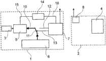
图1示出了在采集医学相关的数据时的医学数据传输系统的实施例的示意图;FIG. 1 shows a schematic diagram of an embodiment of a medical data transmission system when collecting medical-related data;
图2示出了在无线传输医学相关数据时的在第二开关状态中的图1中示出的实施例;FIG. 2 shows the embodiment shown in FIG. 1 in a second switching state during wireless transmission of medically relevant data;
图3示出了在无线传输配置数据时的所描述的实施例;Figure 3 shows the described embodiment when the configuration data is transmitted wirelessly;
图4示出了在依照图3传输配置数据之后的在另一开关状态中的所描述的实施例;FIG. 4 shows the described embodiment in another switching state after transmission of configuration data according to FIG. 3;
图5示出了所描述的数据传输系统的数据总线结构的实施例的示意实施;Figure 5 shows a schematic implementation of an embodiment of a data bus structure of the described data transmission system;
图6示出了所描述的数据传输系统的数据总线结构的另一实施例;Fig. 6 shows another embodiment of the data bus structure of the described data transmission system;
图7示出了医学数据传输系统的另一实例;并且Figure 7 shows another example of a medical data transmission system; and
图8示出了医学数据传输系统的又一实例。Fig. 8 shows yet another example of a medical data transmission system.
图1中示出的医学传输系统包括第一设备1,所述第一设备1预期地由病人携带在身上并且在工作中产生医学相关的数据,所述数据被无线地传输到第二设备2。在所描述的实施例中,第一设备1是具有在病人体内的用于在活的有机体内测量被分析物浓度(例如葡萄糖浓度)的可植入传感器的测量设备。第二设备2是指示设备,所述指示设备具有用于输出所测量的被分析物浓度值的输出装置,例如显示器。The medical transmission system shown in FIG. 1 comprises a
第一设备1包含通信单元7,所述通信单元7包含发送器、接收器和用于控制与第二设备2的通信的微处理器。同样地,第二设备2包含通信单元8,所述通信单元8包含发送器、接收器和用于控制与第一设备1的通信的微处理器。The
医学相关的数据在第一设备中作为测量数据借助于电路被产生,所述电路除了传感器3之外包含微处理器5。该微处理器5控制第一设备的基本功能,所述基本功能在所描述的实施例中是产生测量数据,但是例如也可以是治疗病人,例如通过注入药剂。数据产生电路的微处理器5因此在本申请的范围内也被视为系统处理器。数据产生电路3,5和通信单元7各自经由分离的供电线路15,16连接到能量源14,例如电池。该能量源14既不可以被数据产生电路3,5关断,也不可以被通信单元7关断。The medically relevant data are generated in the first device as measurement data by means of an electrical circuit which, besides the
在所描述的实施例中,模拟的传感器信号(例如与所寻找的测量量相关的电流强度)利用微处理器5的模数转换器被数字化并经受预分析。在该预分析中,传感器3的数字化的原始数据(所述原始数据以例如1秒的第一时间间隔被获得)被压缩,并且由此产生针对例如1分钟的第二时间间隔的测量数据。该数据压缩例如可以通过取平均值来实现,或者也可以使用复杂的用于数据处理或压缩的方法,诸如在EP 1702559 A2或DE 102004020160 A1中所说明的。In the described exemplary embodiment, the analog sensor signal (for example the current intensity related to the measured variable sought) is digitized by means of an analog-to-digital converter of the
由微处理器5产生的测量数据被存储在转交存储器6中,微处理器5经由第一数据线10被连接到所述转交存储器6。转换开关11位于该第一数据线10中,所述转换开关11在图1中以其第一开关状态被示出,在所述第一开关状态中它闭合第一数据线10,从而产生数据的微处理器5可以将作为医学相关的数据的测量数据写入转交存储器6。The measurement data generated by the
转交存储器6经由第二数据线12被连接到第一设备2的通信单元7。在图1所示出的转换开关11的第一开关状态中,该第二数据线12被断开,从而通信单元7不能够访问转交存储器6。转换开关11在所描述的实施例中仅被通信单元7(确切地说在通信单元7中所包含的微处理器)操作。为此目的,通信单元7经由控制线路13与转换开关相连接。需要时,通信单元7设法取得对转交存储器6的访问可能性,其方式是它借助一信号经由控制线路13操作该转换开关并且将其从图1中所描述的第一开关状态置为图2中所描述的第二开关状态。The hand-
在第二开关状态中,转换开关11断开第一数据线10并闭合第二数据线12,从而此时唯独通信单元7能够访问转交存储器6并读取被存储在其中的测量数据。该测量数据随后被通信单元7作为信号序列20无线传输到第二设备2。在读取转交存储器6之后,通信单元7再度操作转换开关11,以将它置回到它的第一开关状态,从而转交存储器11又可以被数据产生电路(在所描述的实施例中也即连接到传感器3的处理器5)写入测量数据。所读取的数据被通信单元7在转交存储器6中标记为已读或被删除,从而转交存储器6的有关的存储空间又可以被写入。In the second switching state, the
转交存储器6也可以被数据产生电路或者说系统处理器5用作主存储器。但可能的是,数据产生电路或者说系统处理器可以访问分离的存储器,并且在转交存储器中唯独存储数据产生电路与通信单元7之间交换的数据。The
在所描述的实施例中,测量数据的传输通过由第二设备2的通信单元8所发送的请求信号21来触发。在接收这样的请求信号21时,第一设备1的通信单元7操作转换开关11,以便能够读取转交存储器11,并且随后发送所读取的测量数据。由第一设备1以及由第二设备2所发送的信号序列通常始终包含独特的标志,所述标志排除系统陌生的设备的影响。例如面向分组的协议(如蓝牙、Zigbee、HomeRF、Wibree、NFC、IEEE 802.11)或者其他协议可以被用于传输。In the described embodiment, the transmission of the measurement data is triggered by a request signal 21 sent by the
因为转换开关11在不与第一设备1的数据产生电路3,5通信的情况下在其开关状态之间变换,所以所述电路或者说其中包含的微处理器5的写入过程可能被中断并因此被干扰。作为中断写入过程的结果,可能在转交存储器6中形成错误的数据。为了这在稍后的对测量数据的分析中不导致结果的歪曲,测量数据被数据产生电路的微处理器5组合成数据块,并且分别对数据块计算数据校验和(Datensicherungssumme)。在无错误的未被中断的写入过程中,这些数据块与它们各自的数据校验和一起被存储在转交存储器6中。通过检验这些数据校验和,稍后可以确定,在转交存储器6中所存储的数据块是有错误的或是没有错误的。数据校验和可以由通信单元7的微处理器检验,从而有错误的数据块已被提早识别并且根本不会首先被发送给第二设备2。但也可能的是,在第二设备2的分析单元中检验所述的数据校验和,并且在第二设备2中才分拣有错误的数据记录或者只要可能就纠正。优选地,数据校验和既由通信单元7也由第二设备2进行检验。在传输过程中,添加特定于相应协议的校验和。Since the
在所描述的数据传输系统中,数据也可以从第二设备2被传输到第一设备1,所述数据在那里为数据产生电路、特别是其中所包含的微处理器5所需。此类数据例如可以是配置数据,例如对于传感器3最佳的电极电压的值或者控制命令,所述控制命令涉及医学相关的数据的产生。此类配置数据从第二设备2到第一设备1的传输被称为下载(Download),以将该工作模式区别于被称为上载(Upload)的医学相关数据从第一设备1到第二设备2的传输。在图5和图6中所描述的转交存储器6具有报头(Header)6a、为上载数据预留的存储区域6b和为下载数据预留的存储区域6c。In the described data transmission system, data can also be transmitted from the
在图3中示意地被示出的下载模式中,第二设备2的通信单元8首先发送请求信号22,并且在它被第一设备的通信单元7获得之后发送由附图标记23表示的数据,例如为数据产生电路(在所描述的实施例中也即连接到传感器3的微处理器5)所确定的配置数据。通信单元7随后将转换开关11置为第二开关状态,从而通信单元7能够访问转交存储器6并且将所接收的数据存储在那里。随后,通信单元再度操作转换开关11,以将它又置回到它的第一开关状态,在所述第一开关状态中它被连接到数据产生电路,也即其中所包含的微处理器5。也可能的是,布置所述转换开关11,使得它当通信单元变得不活动时自动回到它的第一开关状态。In the download mode shown schematically in FIG. 3, the
因为在数据产生电路3,5与通信单元7之间仅仅经由转交存储器6交换数据,所以数据产生电路的微处理器5不知道,是否在转交存储器6中已提供了对它而言新的下载数据。数据产生电路的微处理器5因而以确定的时间间隔读出转交存储器6的为配置数据或类似者所预留的存储区域6c。为了防止下载数据仅仅不完全地被系统处理器5读取,在所描述的实施例中规定,在完成下载后,通信单元7最早在一时间段过去之后又将转换开关11置为第二开关状态,所述时间段如此大,使得系统处理器5在此期间不依赖何时完成下载在任何情况下都已读出了转交存储器6的下载区域。等待时间例如可以被选择为在系统处理器5读出转交存储器6下载区域的尝试之间的时间间隔的两倍,在所述等待时间内通信单元7的微处理器在一次结束的下载之后不再操作转换开关11。Since data are only exchanged between the
在转交存储器6与通信单元7之间或者在转交存储器6与系统处理器5之间的数据线10,12可以依照图5被构建为并行总线,也即包括多个单根线,例如约30根数据线。在所描述的实施例中设置有8位数据线、16位地址线和3位控制线。优选地,转换开关11在这样的情况下转换这样的并行数据线的所有单个的线。但也可能的是,在转交存储器6与通信单元7之间或者在转交存储器6与系统处理器5之间的数据线10,12被构建为串行的。适合的串行总线系统例如有SPI或ICC。在数据线10,12的此类串行构成中,转交存储器6例如可以被构建为EEPROM,这在供电电压的可能的中止时具有持续的中间存储的优点。但是,特别是在数据线10,12的并行方案中转交存储器例如也可以被构建为RAM存储器,所述RAM存储器对于带有快速存取的系统是特别有利的。The data lines 10, 12 between the
转换开关11原则上可以被实现为机械开关或电子开关,例如晶体管开关。特别是在作为并行总线的数据线10,12的实施方案中,转换开关例如可以被构建为ASIC或者甚至被构建为微处理器,或者包含上述的转换开关。除此之外也存在以下可能性,即利用逻辑元件(AND,NAND,OR,NOR,EXOR,锁存器等)或者借助于可自由编程逻辑器件(PLD)来实现转换开关。The
图7示出了医学数据传输系统的另一实施例,所述实施例主要通过以下方式区别于根据前面的图所说明的数据传输系统,即转换开关11由随机存取处理器17操作,从而数据产生电路的系统处理器5和通信单元7可以分别交替地访问所述转交存储器11。在此,转换时刻可以由随机存取处理器17随意选择,例如可以通过内部随机发生器预先给定。FIG. 7 shows another embodiment of a medical data transmission system which differs from the data transmission system explained with reference to the previous figures mainly in that the
系统处理器5和通信单元11分别具有对中间存储器17,18的访问,在所述中间存储器17,18中可以中间存储为转交存储器6所确定的数据。
图8示出了医学数据传输系统的又一实施例,第一设备30属于所述医学数据传输系统,所述第一设备30预期地由病人携带在身上并且在工作中产生医学相关的数据,所述数据被无线传输到第二设备31的接收器37。第一设备30包含微处理器32,所述微处理器32控制医学相关数据的产生,并借助于电子开关33将该数据调制到由频率发生器34提供的载波频率上以便发射,而且经由天线35发射。该数据被第二设备31接收。因为原则上每个接收器都可以接收该数据,所以所述数据优选地被第一设备30的处理器32加密并且在由第二设备31的处理器36接收之后被解密。Fig. 8 shows another embodiment of the medical data transmission system, the
所述数据的发射单向地进行,也即没有在第一设备与第二设备之间交换控制脉冲。数据保护(Datensicherung)可以通过数据保护码来实现,所述数据保护码针对数据分组被计算并且使得能够检验,数据分组是否已被损坏。数据保护的另一可能性在于,多次发送数据分组,从而提高不受扰的接收的概率。The transmission of the data takes place unidirectionally, ie without exchanging control pulses between the first device and the second device. Data protection can be implemented by means of data protection codes which are calculated for the data packets and enable checking whether the data packets have been corrupted. Another possibility for data protection consists in transmitting data packets multiple times, thereby increasing the probability of undisturbed reception.
以根据图8所描述的方式,首先只能够上载数据。对于下载,可以实现相应的反向信道(例如在另一频率上),所述反向信道以完全反过来的方式被驱动。In the manner described with reference to FIG. 8, only data can be uploaded at first. For downloading, a corresponding counter-channel (for example on another frequency) can be implemented which is driven in exactly the opposite way.
根据图8所说明的用于数据传输的方法也可以被用在根据图1至7所阐述的数据传输系统中。例如所述的产生数据的电路可以被配备发射器,经由所述发射器在特别工作模式中(例如用于测试或评估目的)单向发送。The method for data transmission described with reference to FIG. 8 can also be used in the data transmission system described with reference to FIGS. 1 to 7 . For example the said data-generating circuit may be equipped with a transmitter via which unidirectional transmission in a special mode of operation (for example for testing or evaluation purposes).
所说明的用于数据传输的方法可以被用于有线的以及无线的数据传输,例如也被用于光学的数据传输。转换开关11也可以按相应的方式在设备2中被用在通信单元8与输出单元4之间。可以在第一设备中以及在第二设备中分别装入转换开关11。The described method for data transmission can be used for wired as well as wireless data transmission, for example also for optical data transmission. The
附图标记列表List of reference signs
1 第一设备1 first device
2 第二设备2 second device
3 传感器3 sensors
4 输出装置4 output device
5 微处理器5 microprocessors
6 转交存储器6 handover memory
6a 报头6a header
6b 存储区域6b storage area
6c 存储区域6c storage area
7 通信单元7 Communication unit
8 通信单元8 communication unit
10 第一数据线10 The first data line
11 转换开关11 transfer switch
12 第二数据线12 Second data line
13 控制线路13 control circuit
14 能量源14 energy source
15 供电线路15 power supply lines
16 供电线路16 power supply line
20 信号序列20 signal sequence
21 请求信号21 request signal
22 请求信号22 request signal
30 第一设备30 first equipment
31 第二设备31 Second device
32 微处理器32 microprocessors
33 开关33 switch
34 频率发生器34 frequency generator
35 天线35 antenna
36 处理器36 processors
37 接收器37 Receiver
Claims (12)
Applications Claiming Priority (3)
| Application Number | Priority Date | Filing Date | Title |
|---|---|---|---|
| EP07004859.0 | 2007-03-09 | ||
| EP07004859.0AEP1967132B8 (en) | 2007-03-09 | 2007-03-09 | Medical data transmission system |
| PCT/EP2008/001637WO2008110272A2 (en) | 2007-03-09 | 2008-03-01 | Medical data transmission system |
Publications (2)
| Publication Number | Publication Date |
|---|---|
| CN101626721A CN101626721A (en) | 2010-01-13 |
| CN101626721Btrue CN101626721B (en) | 2011-10-19 |
Family
ID=38358054
Family Applications (1)
| Application Number | Title | Priority Date | Filing Date |
|---|---|---|---|
| CN2008800075284AExpired - Fee RelatedCN101626721B (en) | 2007-03-09 | 2008-03-01 | Medical data transmission system |
Country Status (4)
| Country | Link |
|---|---|
| US (1) | US8477026B2 (en) |
| EP (1) | EP1967132B8 (en) |
| CN (1) | CN101626721B (en) |
| WO (1) | WO2008110272A2 (en) |
Families Citing this family (8)
| Publication number | Priority date | Publication date | Assignee | Title |
|---|---|---|---|---|
| US8160900B2 (en) | 2007-06-29 | 2012-04-17 | Abbott Diabetes Care Inc. | Analyte monitoring and management device and method to analyze the frequency of user interaction with the device |
| US8924159B2 (en) | 2008-05-30 | 2014-12-30 | Abbott Diabetes Care Inc. | Method and apparatus for providing glycemic control |
| US8591410B2 (en) | 2008-05-30 | 2013-11-26 | Abbott Diabetes Care Inc. | Method and apparatus for providing glycemic control |
| US20140273824A1 (en)* | 2013-03-15 | 2014-09-18 | Medtronic, Inc. | Systems, apparatus and methods facilitating secure pairing of an implantable device with a remote device using near field communication |
| EP3744247A1 (en)* | 2013-03-15 | 2020-12-02 | Abbott Diabetes Care, Inc. | Medical device data processing and communication methods and systems |
| CN103514135A (en)* | 2013-05-29 | 2014-01-15 | 深圳市中兴移动通信有限公司 | Mobile storage device and mobile terminal |
| JP2016531663A (en) | 2013-08-01 | 2016-10-13 | ゾール メディカル コーポレイションZOLL Medical Corporation | System and method for utilizing an identification device in a wearable medical treatment device |
| TWI760830B (en)* | 2020-08-28 | 2022-04-11 | 佳易科技股份有限公司 | Storage device and medical apparatus using the same |
Citations (2)
| Publication number | Priority date | Publication date | Assignee | Title |
|---|---|---|---|---|
| US6434429B1 (en)* | 1999-06-25 | 2002-08-13 | Biotronik Mess- Und Therapiegeraete Gmbh & Co. Ingenieurbuero Berlin | Implant with close and long-range telemetry |
| CN1440532A (en)* | 2000-05-16 | 2003-09-03 | 爱科来株式会社 | Measurement data processing system |
Family Cites Families (13)
| Publication number | Priority date | Publication date | Assignee | Title |
|---|---|---|---|---|
| EP0113379B1 (en) | 1982-12-13 | 1987-09-30 | Fraunhofer-Gesellschaft Zur Förderung Der Angewandten Forschung E.V. | Coupler for processors |
| US4622979A (en)* | 1984-03-02 | 1986-11-18 | Cardiac Monitoring, Inc. | User-worn apparatus for monitoring and recording electrocardiographic data and method of operation |
| JPS6446432A (en)* | 1987-08-14 | 1989-02-20 | Omron Tateisi Electronics Co | Electronic hemomanometer |
| US4883064A (en)* | 1987-11-19 | 1989-11-28 | Equimed Corporation | Method and system for gathering electrocardiographic data |
| US6949816B2 (en)* | 2003-04-21 | 2005-09-27 | Motorola, Inc. | Semiconductor component having first surface area for electrically coupling to a semiconductor chip and second surface area for electrically coupling to a substrate, and method of manufacturing same |
| US6014578A (en)* | 1998-08-06 | 2000-01-11 | Meotronic, Inc. | Ambulatory recorder having method of configuring size of data subject to loss in volatile memory |
| US6398727B1 (en)* | 1998-12-23 | 2002-06-04 | Baxter International Inc. | Method and apparatus for providing patient care |
| US6577899B2 (en) | 2000-01-21 | 2003-06-10 | Medtronic Minimed, Inc. | Microprocessor controlled ambulatory medical apparatus with hand held communication device |
| US6633772B2 (en)* | 2000-08-18 | 2003-10-14 | Cygnus, Inc. | Formulation and manipulation of databases of analyte and associated values |
| DE102004020160A1 (en)* | 2004-04-24 | 2005-11-10 | Roche Diagnostics Gmbh | Method and device for monitoring a concentration of an analyte in the living body of a human or animal |
| DE502006001913D1 (en)* | 2005-03-15 | 2008-12-11 | Roche Diagnostics Gmbh | Method and system for the analysis of glucose metabolism |
| US8034002B2 (en)* | 2005-03-17 | 2011-10-11 | Coifman Robert E | Apparatus and method for intelligent electronic peak flow meters |
| US8095123B2 (en)* | 2005-06-13 | 2012-01-10 | Roche Diagnostics International Ag | Wireless communication system |
- 2007
- 2007-03-09EPEP07004859.0Apatent/EP1967132B8/ennot_activeNot-in-force
- 2008
- 2008-03-01CNCN2008800075284Apatent/CN101626721B/ennot_activeExpired - Fee Related
- 2008-03-01WOPCT/EP2008/001637patent/WO2008110272A2/enactiveApplication Filing
- 2009
- 2009-09-09USUS12/556,309patent/US8477026B2/ennot_activeExpired - Fee Related
Patent Citations (2)
| Publication number | Priority date | Publication date | Assignee | Title |
|---|---|---|---|---|
| US6434429B1 (en)* | 1999-06-25 | 2002-08-13 | Biotronik Mess- Und Therapiegeraete Gmbh & Co. Ingenieurbuero Berlin | Implant with close and long-range telemetry |
| CN1440532A (en)* | 2000-05-16 | 2003-09-03 | 爱科来株式会社 | Measurement data processing system |
Also Published As
| Publication number | Publication date |
|---|---|
| CN101626721A (en) | 2010-01-13 |
| EP1967132A1 (en) | 2008-09-10 |
| WO2008110272A3 (en) | 2008-10-30 |
| EP1967132B8 (en) | 2015-06-03 |
| US8477026B2 (en) | 2013-07-02 |
| US20100141429A1 (en) | 2010-06-10 |
| HK1140399A1 (en) | 2010-10-15 |
| EP1967132B1 (en) | 2015-03-04 |
| WO2008110272A2 (en) | 2008-09-18 |
Similar Documents
| Publication | Publication Date | Title |
|---|---|---|
| CN101626721B (en) | Medical data transmission system | |
| US7908334B2 (en) | System and method for addressing implantable devices | |
| US10617296B2 (en) | Method and system for providing data communication in continuous glucose monitoring and management system | |
| US8187183B2 (en) | Continuous glucose monitoring system and methods of use | |
| CN116097232A (en) | Secure communication in medical monitoring systems | |
| US7237712B2 (en) | Implantable device and communication integrated circuit implementable therein | |
| WO2008011593A2 (en) | System and method for addressing implantable devices | |
| EP2425238A1 (en) | An addressable integrated circuit and method thereof | |
| CN119585805A (en) | Dynamic discovery window for wireless communication between devices | |
| US20250306779A1 (en) | Over-the-Air Programming of Sensing Devices | |
| WO2014110487A1 (en) | Synchronizing wireless data acquisition of physiological information | |
| HK1140399B (en) | Medical data transmission system | |
| Cao et al. | Secure method for software upgrades for implantable medical devices | |
| JP2024504669A (en) | Multi-sensor system for intraoral area | |
| CN117751412A (en) | Over-the-air programming of sensing devices | |
| Dimitrov | Wireless module for distance measurement of patient’s temperature in hospitals | |
| WO2022172802A1 (en) | Wireless communication system, wireless communication method, wireless communication device, and program | |
| Sheth | Head movement detection system using Rabbit microprocessor |
Legal Events
| Date | Code | Title | Description |
|---|---|---|---|
| C06 | Publication | ||
| PB01 | Publication | ||
| C10 | Entry into substantive examination | ||
| SE01 | Entry into force of request for substantive examination | ||
| REG | Reference to a national code | Ref country code:HK Ref legal event code:DE Ref document number:1140399 Country of ref document:HK | |
| C14 | Grant of patent or utility model | ||
| GR01 | Patent grant | ||
| REG | Reference to a national code | Ref country code:HK Ref legal event code:GR Ref document number:1140399 Country of ref document:HK | |
| CF01 | Termination of patent right due to non-payment of annual fee | ||
| CF01 | Termination of patent right due to non-payment of annual fee | Granted publication date:20111019 Termination date:20200301 |