CN101621714B - Node and data processing system and data processing method - Google Patents
Node and data processing system and data processing methodDownload PDFInfo
- Publication number
- CN101621714B CN101621714BCN2008101282156ACN200810128215ACN101621714BCN 101621714 BCN101621714 BCN 101621714BCN 2008101282156 ACN2008101282156 ACN 2008101282156ACN 200810128215 ACN200810128215 ACN 200810128215ACN 101621714 BCN101621714 BCN 101621714B
- Authority
- CN
- China
- Prior art keywords
- optical burst
- optical
- burst
- channel
- cross
- Prior art date
- Legal status (The legal status is an assumption and is not a legal conclusion. Google has not performed a legal analysis and makes no representation as to the accuracy of the status listed.)
- Active
Links
Images


Classifications
- H—ELECTRICITY
- H04—ELECTRIC COMMUNICATION TECHNIQUE
- H04J—MULTIPLEX COMMUNICATION
- H04J3/00—Time-division multiplex systems
- H04J3/02—Details
- H04J3/06—Synchronising arrangements
- H04J3/0635—Clock or time synchronisation in a network
- H04J3/0638—Clock or time synchronisation among nodes; Internode synchronisation
- H04J3/0658—Clock or time synchronisation among packet nodes
- H—ELECTRICITY
- H04—ELECTRIC COMMUNICATION TECHNIQUE
- H04J—MULTIPLEX COMMUNICATION
- H04J14/00—Optical multiplex systems
- H04J14/02—Wavelength-division multiplex systems
- H04J14/0201—Add-and-drop multiplexing
- H04J14/0202—Arrangements therefor
- H04J14/021—Reconfigurable arrangements, e.g. reconfigurable optical add/drop multiplexers [ROADM] or tunable optical add/drop multiplexers [TOADM]
- H04J14/0212—Reconfigurable arrangements, e.g. reconfigurable optical add/drop multiplexers [ROADM] or tunable optical add/drop multiplexers [TOADM] using optical switches or wavelength selective switches [WSS]
- H—ELECTRICITY
- H04—ELECTRIC COMMUNICATION TECHNIQUE
- H04J—MULTIPLEX COMMUNICATION
- H04J14/00—Optical multiplex systems
- H04J14/02—Wavelength-division multiplex systems
- H04J14/0201—Add-and-drop multiplexing
- H04J14/0202—Arrangements therefor
- H04J14/0213—Groups of channels or wave bands arrangements
- H—ELECTRICITY
- H04—ELECTRIC COMMUNICATION TECHNIQUE
- H04J—MULTIPLEX COMMUNICATION
- H04J14/00—Optical multiplex systems
- H04J14/02—Wavelength-division multiplex systems
- H04J14/0278—WDM optical network architectures
- H04J14/0284—WDM mesh architectures
- H—ELECTRICITY
- H04—ELECTRIC COMMUNICATION TECHNIQUE
- H04L—TRANSMISSION OF DIGITAL INFORMATION, e.g. TELEGRAPHIC COMMUNICATION
- H04L45/00—Routing or path finding of packets in data switching networks
- H04L45/62—Wavelength based
- H—ELECTRICITY
- H04—ELECTRIC COMMUNICATION TECHNIQUE
- H04Q—SELECTING
- H04Q11/00—Selecting arrangements for multiplex systems
- H04Q11/0001—Selecting arrangements for multiplex systems using optical switching
- H04Q11/0005—Switch and router aspects
- H—ELECTRICITY
- H04—ELECTRIC COMMUNICATION TECHNIQUE
- H04Q—SELECTING
- H04Q11/00—Selecting arrangements for multiplex systems
- H04Q11/0001—Selecting arrangements for multiplex systems using optical switching
- H04Q11/0062—Network aspects
- H04Q11/0066—Provisions for optical burst or packet networks
- H—ELECTRICITY
- H04—ELECTRIC COMMUNICATION TECHNIQUE
- H04J—MULTIPLEX COMMUNICATION
- H04J14/00—Optical multiplex systems
- H04J14/02—Wavelength-division multiplex systems
- H04J14/0201—Add-and-drop multiplexing
- H04J14/0202—Arrangements therefor
- H04J14/0205—Select and combine arrangements, e.g. with an optical combiner at the output after adding or dropping
- H—ELECTRICITY
- H04—ELECTRIC COMMUNICATION TECHNIQUE
- H04J—MULTIPLEX COMMUNICATION
- H04J14/00—Optical multiplex systems
- H04J14/02—Wavelength-division multiplex systems
- H04J14/0278—WDM optical network architectures
- H04J14/0283—WDM ring architectures
- H—ELECTRICITY
- H04—ELECTRIC COMMUNICATION TECHNIQUE
- H04J—MULTIPLEX COMMUNICATION
- H04J14/00—Optical multiplex systems
- H04J14/02—Wavelength-division multiplex systems
- H04J14/0278—WDM optical network architectures
- H04J14/0286—WDM hierarchical architectures
- H—ELECTRICITY
- H04—ELECTRIC COMMUNICATION TECHNIQUE
- H04Q—SELECTING
- H04Q11/00—Selecting arrangements for multiplex systems
- H04Q11/0001—Selecting arrangements for multiplex systems using optical switching
- H04Q11/0062—Network aspects
- H04Q11/0071—Provisions for the electrical-optical layer interface
- H—ELECTRICITY
- H04—ELECTRIC COMMUNICATION TECHNIQUE
- H04Q—SELECTING
- H04Q11/00—Selecting arrangements for multiplex systems
- H04Q11/0001—Selecting arrangements for multiplex systems using optical switching
- H04Q11/0005—Switch and router aspects
- H04Q2011/0037—Operation
- H04Q2011/0045—Synchronisation
- H—ELECTRICITY
- H04—ELECTRIC COMMUNICATION TECHNIQUE
- H04Q—SELECTING
- H04Q11/00—Selecting arrangements for multiplex systems
- H04Q11/0001—Selecting arrangements for multiplex systems using optical switching
- H04Q11/0062—Network aspects
- H04Q2011/0064—Arbitration, scheduling or medium access control aspects
Landscapes
- Engineering & Computer Science (AREA)
- Computer Networks & Wireless Communication (AREA)
- Signal Processing (AREA)
- Optical Communication System (AREA)
- Data Exchanges In Wide-Area Networks (AREA)
Abstract
Translated fromChinese
Description
Translated fromChinese技术领域technical field
本发明实施例涉及通信领域,特别涉及一种节点、数据处理系统和数据处理方法。 The embodiments of the present invention relate to the communication field, and in particular to a node, a data processing system and a data processing method. the
背景技术Background technique
通信网络中的节点按其功能可分为源节点、目的节点和中间节点,源节点是充当信源发送业务数据的节点,目的节点是充当宿源接收业务数据的节点,中间节点是转发业务数据的节点,换言之,有业务数据上路的节点可以称为源节点,有业务数据下路的节点可以称为目的节点。通信网络主要由上层的数据通信网络和下层的传送网络组成,通信网络按照网络拓扑结构可分为核心网络和汇聚网络,那么位于核心网络中的节点可称为核心节点,位于汇聚网络中的节点可称为边缘节点。核心节点主要由上层的数据通信网络中的核心路由器以及下层的传送网络中的波长分叉复用设备组成,边缘节点主要由上层的数据通信网络中的边缘路由器以及下层的传送网络中的波长分叉复用设备组成。例如,上述通信网络中的边缘节点和核心节点当有业务上路和下路时可分别作为源节点和目的节点,当没有业务上路和下路时可作为中间节点。在上述通信网络中通常边缘节点是作为源节点和目的节点,而核心节点是作为中间节点。随着高宽带业务的兴起和宽带用户数量的增长,通信网络中的网络流量呈指数增长,导致对节点中的路由器容量和功耗的要求越来越高。目前,为了支持通信网络中的业务数据传送,路由器的容量和功耗都已经发展到了无法承受的地步,并且资金花费和运作花费高昂。因此,降低节点中路由器的容量和功耗,即降低节点的容量和功耗,尤其是降低节点的功耗是当前亟待解决的问题。 The nodes in the communication network can be divided into source nodes, destination nodes and intermediate nodes according to their functions. The source node is a node that acts as a source to send business data, the destination node is a node that acts as a sink source to receive business data, and the intermediate node is a node that forwards business data. In other words, a node with service data on the road can be called a source node, and a node with business data off the road can be called a destination node. The communication network is mainly composed of an upper-layer data communication network and a lower-layer transmission network. The communication network can be divided into a core network and an aggregation network according to the network topology. The nodes in the core network can be called core nodes, and the nodes in the aggregation network may be referred to as edge nodes. The core node is mainly composed of the core router in the upper layer data communication network and the wavelength bifurcation multiplexing equipment in the lower layer transmission network. Cross-multiplexing equipment composition. For example, the edge nodes and core nodes in the communication network above can serve as source nodes and destination nodes respectively when there is service on and off, and can serve as intermediate nodes when there is no service on and off. In the above-mentioned communication network, edge nodes are usually used as source nodes and destination nodes, while core nodes are used as intermediate nodes. With the rise of high-bandwidth services and the increase in the number of broadband users, the network traffic in the communication network increases exponentially, resulting in higher and higher requirements on the capacity and power consumption of routers in nodes. At present, in order to support the transmission of service data in the communication network, the capacity and power consumption of routers have developed to an unbearable level, and the capital and operation costs are high. Therefore, reducing the capacity and power consumption of the router in the node, that is, reducing the capacity and power consumption of the node, especially reducing the power consumption of the node is an urgent problem to be solved at present. the
针对上述问题,现有技术一提出了一种解决方案,现有技术一是在通信网络中,节点,尤其是核心节点,利用波长交叉连接设备或OTN交叉连接设备代替原有的波长分插复用设备,此方案中非本地下路的业务数据经过节点时可以直接在波长层或ODU层穿通,由于节点的波长交叉连接设备或OTN交叉连接设备的电处理效率高,因此,现有技术一的技术方案可以在某种程度上降低节点的功耗,尤其是降低核心节点的功耗。 Aiming at the above problems, prior art 1 proposes a solution. In prior art 1, in a communication network, nodes, especially core nodes, use wavelength cross-connect equipment or OTN cross-connect equipment to replace the original wavelength add-drop multiplexing In this solution, the non-local downlink service data can pass through the wavelength layer or ODU layer directly when passing through the node. Since the wavelength cross-connect device or OTN cross-connect device of the node has high electrical processing efficiency, the existing technology The technical solution can reduce the power consumption of nodes to some extent, especially the power consumption of core nodes. the
针对上述问题,现有技术二提出了另一种解决方案,即全光交换技术,例如,光突发交换(Optical Burst Switch)技术。OBS技术的主要思想是使光突发通道与控制通道在物理上分离,分别传送光突发数据和控制通道,节点仅对控制通道进行电处理,根据控制通道中携带的信息为即将到来的光突发数据预留资源,使光突发数据经过节点时无需进行光电转换,可直接在光层实现传送和交换,从而减少了节点的电处理过程,降低了节点的功耗。 To address the above problems, prior art 2 proposes another solution, that is, an all-optical switching technology, for example, an optical burst switching (Optical Burst Switch) technology. The main idea of OBS technology is to physically separate the optical burst channel from the control channel, and transmit the optical burst data and the control channel separately. Resources are reserved for burst data, so that optical burst data can be transmitted and switched directly at the optical layer without photoelectric conversion when passing through nodes, thereby reducing the electrical processing process of nodes and power consumption of nodes. the
但是,在实现本发明过程中,发明人发现现有技术中至少存在如下问题: But, in realizing the present invention process, inventor finds that there is following problem at least in prior art:
现有技术一中的技术方案中由于业务数据在节点穿通的波长层或ODU层的颗粒大,因此采用波长或者ODU路径连接节点的带宽过大,采用波长或者ODU路径连接节点相当于在节点间提供了直达的路径,尤其是边缘节点,该路径的数量近似与节点的数量呈平方关系(n*(n-1)/2,n为节点的路由器数量),当节点需要连接更多的节点时,需要的路径数量庞大,需要的连接数增加,并且节点需要提供更多的端口来连接更多的节点,这导致节点的体积、功耗和成本增大。 In the technical solution of prior art 1, since the granularity of service data in the wavelength layer or ODU layer through which nodes pass through is large, the bandwidth of connecting nodes using wavelength or ODU paths is too large. Using wavelengths or ODU paths to connect nodes is equivalent to connecting nodes between nodes. Provides a direct path, especially the edge node, the number of the path is approximately quadratic with the number of nodes (n*(n-1)/2, n is the number of routers of the node), when the node needs to connect more nodes When , the number of required paths is huge, the number of required connections increases, and the node needs to provide more ports to connect more nodes, which leads to an increase in the size, power consumption and cost of the node. the
现有技术二虽然降低了节点的功耗,但由于光突发交换技术缺乏合适的光缓存器,使得数据在OBS系统中传输时容易在光层产生冲突。 Although the second prior art reduces the power consumption of nodes, due to the lack of a suitable optical buffer in the optical burst switching technology, it is easy to cause conflicts at the optical layer when data is transmitted in the OBS system. the
发明内容Contents of the invention
本发明实施例提供了一种节点、数据处理系统和数据处理方法,克服了现有技术中节点的体积、功耗和成本大以及全光交换中光层产生数据冲突的 缺陷,从而降低了节点的体积、功耗和成本以及避免了全光交换中光层产生数据冲突的问题。 Embodiments of the present invention provide a node, a data processing system, and a data processing method, which overcome the defects of large size, power consumption, and cost of nodes in the prior art, and data conflicts at the optical layer in all-optical switching, thereby reducing the number of nodes. The size, power consumption and cost of the all-optical switching avoid the problem of data conflicts in the optical layer. the
本发明实施例提供了一种节点,包括: An embodiment of the present invention provides a node, including:
控制模块,用于生成同步信息和光突发配置信息; A control module, configured to generate synchronization information and optical burst configuration information;
至少一个同步处理模块,用于根据所述同步信息对一个或多个波长上的光突发通道进行同步处理; At least one synchronization processing module, configured to perform synchronization processing on optical burst channels on one or more wavelengths according to the synchronization information;
交叉连接模块,用于根据所述光突发配置信息对同步处理后的光突发通道进行交叉连接处理。 A cross-connect module, configured to perform cross-connect processing on the synchronously processed optical burst channels according to the optical burst configuration information. the
本发明实施例还提供了一种数据处理系统,包括:至少二个节点,所述节点间采用一个或多个波长上的光突发通道进行连接,所述节点用于将业务数据通过所述光突发通道进行传送。 The embodiment of the present invention also provides a data processing system, including: at least two nodes, the nodes are connected by optical burst channels on one or more wavelengths, and the nodes are used to transmit service data through the Optical burst channel for transmission. the
本发明实施例还提供了一种数据处理方法,包括:控制模块生成同步信息和光突发配置信息;同步处理模块根据所述同步信息对一个或多个波长上的光突发通道进行同步处理;交叉连接模块根据所述光突发配置信息对同步处理后的光突发通道进行交叉连接处理。 The embodiment of the present invention also provides a data processing method, including: the control module generates synchronization information and optical burst configuration information; the synchronization processing module performs synchronization processing on the optical burst channels on one or more wavelengths according to the synchronization information; The cross-connection module performs cross-connection processing on the synchronously processed optical burst channels according to the optical burst configuration information. the
本发明实施例又提供了一种数据处理方法,包括:节点间采用一个或多个波长上的光突发通道进行连接,所述节点将业务数据通过所述光突发通道进行传送。 The embodiment of the present invention further provides a data processing method, including: nodes are connected using optical burst channels on one or more wavelengths, and the nodes transmit service data through the optical burst channels. the
本发明实施例的技术方案中,通过在一个波长上划分多个OB通道,使数据处理系统的节点间可通过OB通道来传送业务数据,从而降低了节点间的连接带宽,节点的端口上可包括多个OB通道,使节点可以通过多个OB通道连接更多的节点,增加了节点的可用连接数,同时对于一个节点而言,在连接数相同的情况下,可以减少节点端口的数量,从而降低了节点的体积、功耗以及成本;OB通道是配置的,相对固定,节点通过光突发配置信息对OB通道进行交叉连接处理,避免了全光交换中由于缺乏光缓存器而在光层产生数据冲突的问题;节点对OB通道进行的同步和交叉连接处理是在光层完成的, 减少了光电、电光转换以及电处理过程,降低了节点的功耗、体积以及成本。 In the technical solution of the embodiment of the present invention, by dividing multiple OB channels on one wavelength, the nodes of the data processing system can transmit service data through the OB channels, thereby reducing the connection bandwidth between nodes, and the ports of the nodes can Including multiple OB channels, so that the node can connect more nodes through multiple OB channels, increasing the number of available connections of the node. At the same time, for a node, when the number of connections is the same, the number of node ports can be reduced. This reduces the size, power consumption and cost of the node; the OB channel is configured and relatively fixed, and the node performs cross-connection processing on the OB channel through the optical burst configuration information, avoiding the lack of optical buffers in the all-optical switching The problem of data conflicts at the layer; the synchronization and cross-connection processing of the OB channel by the node is completed at the optical layer, which reduces the photoelectric, electro-optical conversion and electrical processing processes, and reduces the power consumption, volume and cost of the node. the
附图说明Description of drawings
图1为本发明实施例中通信网络的结构示意图; Fig. 1 is the structural representation of communication network in the embodiment of the present invention;
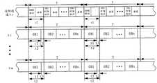
图2为本发明实施例中OB通道的结构示意图; Fig. 2 is the structural representation of OB channel in the embodiment of the present invention;
图3为本发明实施例中OB的物理格式示意图; Fig. 3 is the schematic diagram of the physical format of OB in the embodiment of the present invention;
图4为本发明节点实施例一的结构示意图; Fig. 4 is a schematic structural diagram of node embodiment 1 of the present invention;
图5为本发明节点实施例二的结构示意图; Figure 5 is a schematic structural diagram of the second embodiment of the node of the present invention;
图6为本发明节点实施例一中控制通道与OB通道的时序关系图; FIG. 6 is a timing relationship diagram between the control channel and the OB channel in node embodiment 1 of the present invention;
图7为本发明节点中交叉连接模块的结构示意图之一; Fig. 7 is one of structural representations of the cross-connect module in the node of the present invention;
图8为本发明节点中交叉连接模块的结构示意图之二; Fig. 8 is the second structural diagram of the cross-connect module in the node of the present invention;
图9为本发明节点实施例三的结构示意图; Figure 9 is a schematic structural diagram of the third embodiment of the node of the present invention;
图10为本发明节点中交叉连接模块的结构示意图之三; Fig. 10 is the third structural diagram of the cross-connect module in the node of the present invention;
图11为本发明节点实施例四的结构示意图; Figure 11 is a schematic structural diagram of the fourth embodiment of the node of the present invention;
图12为本发明节点实施例四中光功率包络信号与OB时隙时钟的示意图; Fig. 12 is a schematic diagram of the optical power envelope signal and the OB time slot clock in the fourth node embodiment of the present invention;
图13为本发明节点中交叉连接模块的结构示意图之四; Fig. 13 is the fourth structural diagram of the cross-connect module in the node of the present invention;
图14为本发明节点中交叉连接模块的结构示意图之五。 FIG. 14 is a fifth structural schematic diagram of a cross-connect module in a node of the present invention. the
具体实施方式Detailed ways
下面通过附图和实施例,对本发明实施例的技术方案做进一步的详细描述。 The technical solutions of the embodiments of the present invention will be described in further detail below with reference to the drawings and embodiments. the
为能更清楚的描述本发明实施例中的节点和数据处理系统,本发明实施例以一个通信网络为例,但此通信网络不应成为对本发明的限制。图1为本发明实施例中通信网络的结构示意图,如图1所示,该通信网络由核心网络和汇聚网络组成,核心网络包括节点C1、C2、C3和C4,C1、C2、C3和C4作为核心节点;C1、C2、C3和C4分别对应一个汇聚网络,汇聚网络包括多个节点,例如,C1对应的汇聚网络中包括节点C1N1、C1N2......C1N10,C1N1、C1N2......C1N10作为边缘节点。在本发明实施例的技术方案中,通信网络的节点间是通过光突发(Optical Burst,以下简称OB)通道来传送业务数据的,节点间是通过OB通道连接的,OB通道为在光纤的一个或者多个波长上划分出的子波长通道,节点通过对承载业务数据的OB通道对应的OB进行处理,从而实现对OB通道的处理。图2为本发明实施例中OB通道的结构示意图,如图2所示,例如,一根光纤包括多个波长λ1、λ2......λm,在λ1、λ2......λm上分别划分出数个时隙,称为OB时隙,t2为OB时隙的长度;OB时隙中的有效载荷为OB,OB长度为t1,在t1时间内激光器开启时才可能有数据传输;t3为保护时间,保护时间主要指OB发送、接收以及切换时,光器件开启、关闭所需的时间。多个OB时隙组成一帧,称为OB帧,T为帧周期,图中所示为OB1至OBn组成一帧。在一个波长中,以T为单位周期性发送OB帧。其中OB1、OB2......OBn的长度可以相同,也可以不同,即划分的OB时隙的长度可以相同,也可以不同。不同周期同一位置的OB组成一个OB通道,例如OB1通道、OB2通道......OBn通道等。首先业务数据会被适配成OB,因为业务数据是分组传送的,所以业务数据按分组适配成多个OB,这些OB再以时间间隔T进行传送,从而完成整个业务数据的传送,这些以时间间隔T进行传送的OB就组成了OB通道。例如,业务数据被适配成多个OB1,OB1再以时间间隔T进行传送,这些以时间间隔T进行传送的OB1就组成了OB1通道,多个OB1承载业务数据,即OB1通道承载该业务数据。承载业务数据的OB通道可以是一个波长上的OB通道,例如λ1上的OB1通道;可以是一个波长上的多个OB通道,例如λ1上的OB1通道、OB2通道和OB3通道;也可以是多个波长上的对应的同一位置上的OB组成的OB通道,例如,可以是一根光纤中部分波长上的OB1或者是所有波长上的OB1组成的通道;还可以是多个波长上的多个对应的同一位置上的OB组成的多个OB通道,例如,可以是一根光纤中部分波长上的OB1组成的OB通道和OB2组成的OB通道或 者是所有波长上的OB1组成的通道和OB2组成的通道。图1中的节点间是通过OB通道连接的,例如,图1中示出三个OB通道,分别为连接C2N1和C3N10的λ1上的OB2通道、连接C1N10和C3N1的λ1上的OB3通道以及连接C1N10和C3N2的λ2上的OB2通道。例如,从C2N1发往C3N10的业务数据采用λ1上的OB2通道承载。图3为本发明实施例中OB的物理格式示意图,如图3所示,一个OB主要包括功率锁定、定时、定界、开销和净荷,其中,功率锁定用于突发接收机锁定OB的功率,定时用于突发接收机锁定OB的时钟,定界用于定出OB的边界,OB开销中包含有OB通道的信息,净荷承载的是OB的净荷,即突发容器(Burst Container,以下简称BC)。OB通道需要配置,具体可以采用静态配置或动态配置。其中静态配置可以为手工配置,通过命令行或者网络管理平面进行配置;动态配置可以通过控制平面进行自动配置,例如基于控制平面协议通用多协议标志交换协议(Genera lized Multiprotocol Label Switching,简称GMPLS)或自动交换光网络(Automatic Switch Optical Network,简称ASON)进行自动配置。In order to describe the nodes and the data processing system in the embodiment of the present invention more clearly, the embodiment of the present invention takes a communication network as an example, but the communication network should not be a limitation of the present invention. Fig. 1 is a schematic structural diagram of a communication network in an embodiment of the present invention. As shown in Fig. 1, the communication network is composed of a core network and an aggregation network, and the core network includes nodes C1, C2, C3 and C4, C1, C2, C3 and C4 As core nodes; C1, C2, C3 and C4 respectively correspond to a convergence network, and the convergence network includes multiple nodes. For example, the convergence network corresponding to C1 includes nodes C1N1, C1N2...C1N10, C1N1, C1N2.. ...C1N10 as an edge node. In the technical solution of the embodiment of the present invention, the nodes of the communication network transmit service data through an optical burst (Optical Burst, hereinafter referred to as OB) channel, and the nodes are connected through an OB channel, and the OB channel is an optical fiber channel. For the sub-wavelength channels divided on one or more wavelengths, the node processes the OB channel corresponding to the OB channel carrying service data, so as to realize the processing of the OB channel. Fig. 2 is a schematic structural diagram of an OB channel in an embodiment of the present invention, as shown in Fig. 2, for example, an optical fiber includes multiple wavelengths λ1, λ2...λm, and in λ1, λ2... λm is divided into several time slots, which are called OB time slots, and t2 is the length of the OB time slot; the payload in the OB time slot is OB, and the length of the OB is t1. Data may only be available when the laser is turned on within t1 Transmission; t3 is the protection time, which mainly refers to the time required for the optical device to be turned on and off when the OB is sending, receiving and switching. A plurality of OB time slots form a frame, which is called an OB frame, and T is the frame period, as shown in the figure, OB1 to OBn form a frame. In one wavelength, OB frames are periodically sent in units of T. The lengths of OB1, OB2...OBn can be the same or different, that is, the lengths of the divided OB time slots can be the same or different. OBs at the same position in different cycles form an OB channel, such as OB1 channel, OB2 channel...OBn channel, etc. First of all, the business data will be adapted into OBs, because the business data is transmitted in groups, so the business data will be adapted into multiple OBs according to the groups, and these OBs will be transmitted at a time interval T to complete the transmission of the entire business data. The OBs that are transmitted at time interval T constitute the OB channel. For example, business data is adapted into multiple OB1s, and OB1s are transmitted at time intervals T. These OB1s transmitted at time intervals T form OB1 channels. Multiple OB1s carry business data, that is, OB1 channels carry the business data. . The OB channel carrying service data can be an OB channel on one wavelength, such as OB1 channel on λ1; it can be multiple OB channels on one wavelength, such as OB1 channel, OB2 channel and OB3 channel on λ1; it can also be multiple The OB channel composed of OBs corresponding to the same position on each wavelength, for example, can be a channel composed of OB1 on some wavelengths in an optical fiber or OB1 on all wavelengths; it can also be multiple channels on multiple wavelengths Corresponding to multiple OB channels composed of OBs at the same position, for example, it can be an OB channel composed of OB1 and OB2 on some wavelengths in an optical fiber or a channel composed of OB1 and OB2 on all wavelengths composed of channels. The nodes in Figure 1 are connected through OB channels. For example, Figure 1 shows three OB channels, which are the OB2 channel on λ1 connecting C2N1 and C3N10, the OB3 channel on λ1 connecting C1N10 and C3N1, and the connection OB2 channel on λ2 of C1N10 and C3N2. For example, the service data sent from C2N1 to C3N10 is carried by the OB2 channel on λ1. Figure 3 is a schematic diagram of the physical format of the OB in the embodiment of the present invention. As shown in Figure 3, an OB mainly includes power locking, timing, demarcation, overhead and payload, wherein the power locking is used for the burst receiver to lock the OB The power and timing are used for the burst receiver to lock the clock of the OB, and the delimitation is used to define the boundary of the OB. The OB overhead contains the information of the OB channel, and the payload carries the payload of the OB, that is, the burst container (Burst container) Container, hereinafter referred to as BC). The OB channel needs to be configured, which can be static configuration or dynamic configuration. Wherein the static configuration can be manually configured, configured through the command line or the network management plane; the dynamic configuration can be automatically configured through the control plane, such as based on the control plane protocol General Multiprotocol Label Switching (Generated Multiprotocol Label Switching, referred to as GMPLS) or Automatically switch optical network (Automatic Switch Optical Network, referred to as ASON) for automatic configuration.
本发明实施例通过在一个波长上划分多个OB通道,节点间可通过OB通道来传送业务数据。OB通道的带宽小,降低了节点间的连接带宽,节点的端口上包括多个OB通道,使节点可以通过OB通道连接更多的节点,增加了节点的可用连接数,同时对于一个节点而言,在连接数相同的情况下,可以减少节点端口的数量,从而降低了节点的体积、功耗以及成本;由于不同的OB通道时间上是分离的,相互独立,因此一个OB通道的配置变更不会影响其他OB通道,使OB通道配置变更更安全,有利于实现OB通道的动态配置。 In the embodiment of the present invention, by dividing multiple OB channels on one wavelength, service data can be transmitted between nodes through the OB channels. The bandwidth of the OB channel is small, which reduces the connection bandwidth between nodes. The port of the node includes multiple OB channels, so that the node can connect more nodes through the OB channel, increasing the number of available connections of the node. At the same time, for a node , in the case of the same number of connections, the number of node ports can be reduced, thereby reducing the size, power consumption and cost of the node; because different OB channels are separated in time and independent of each other, the configuration change of an OB channel does not change It will affect other OB channels, making OB channel configuration changes more secure, and conducive to the realization of dynamic configuration of OB channels. the
图4为本发明节点实施例一的结构示意图,如图4所示,节点包括控制模块11、同步处理模块12和交叉连接模块13。控制模块11用于生成同步信息,并将同步信息发送到同步处理模块12;控制模块11还用于生成光突发配置信息,并将光突发配置信息发送到交叉连接模块13。同步处理模块12根据同步信息对一个或多个波长上的OB通道进行同步处理,并将同步处理后 的OB通道发送到交叉连接模块13。交叉连接模块13根据光突发配置信息对同步处理后的OB通道进行交叉连接处理。本实施例中同步处理模块12可以为一个或多个,图4中只示出一个。 FIG. 4 is a schematic structural diagram of a node embodiment 1 of the present invention. As shown in FIG. 4 , the node includes a
本实施例中的节点的端口上包括多个OB通道,节点可以通过多个OB通道连接更多的节点,增加了节点的可用连接数,同时对于一个节点而言,在连接数相同的情况下,可以减少节点端口的数量,从而降低了节点的体积、功耗以及成本;本实施例中OB通道是配置的,相对固定,节点可通过光突发配置信息对OB通道进行交叉连接处理,避免了全光交换中由于缺乏光缓存器而在光层产生数据冲突的问题;本实施例中的节点对OB通道进行的同步和交叉连接处理是在光层完成的,减少了光电、电光转换以及电处理过程,降低了节点的功耗。 The port of the node in this embodiment includes multiple OB channels, and the node can connect more nodes through multiple OB channels, which increases the number of available connections of the node. At the same time, for a node, when the number of connections is the same , can reduce the number of node ports, thereby reducing the size, power consumption and cost of the node; in this embodiment, the OB channel is configured and relatively fixed, and the node can perform cross-connection processing on the OB channel through the optical burst configuration information to avoid The problem of data conflicts in the optical layer due to the lack of optical buffers in all-optical switching is solved; the synchronization and cross-connection processing of the nodes on the OB channel in this embodiment is completed in the optical layer, reducing the need for photoelectric, electro-optical conversion and The electrical processing process reduces the power consumption of the node. the
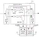
图5为本发明节点实施例二的结构示意图,如图5所示,节点包括控制模块11、同步处理模块12和交叉连接模块13。控制模块11包括检测单元111、生成单元112、配置信息生成单元113,其中,检测单元111用于从预先分离的信号中检测出OB帧头时钟和OB时隙时钟,并将OB帧头时钟发送给同步处理模块12,本实施例中预先分离的信号为控制通道;生成单元112用于对OB帧头时钟和OB时隙时钟进行处理生成新OB帧头时钟和新OB时隙时钟,并将新OB帧头时钟发送给同步处理模块12;配置信息生成单元113,用于根据预先设置的光突发通道配置信息以及新OB帧头时钟和新OB时隙时钟生成光突发配置信息,并将光突发配置信息发送给交叉连接模块13,本实施例中光突发通道配置信息包括连接节点的OB通道的信息,即包括节点间通过一个或多个OB通道进行连接的信息。而光突发配置信息在光突发通道配置信息的基础上还包括各个OB通道的时序关系,即在交叉连接处理过程中交叉连接模块13根据光突发配置信息对组成OB通道的OB进行交叉连接处理,从而实现对OB通道的交叉连接处理。同步处理模块12包括阵列控制单元121和阵列单元122,阵列控制单元121用于根据OB帧头时钟和新OB帧头时钟生 成阵列控制信息,阵列单元122用于根据阵列控制信息配置光延时阵列,通过光延时阵列对一个或多个波长中的OB通道进行同步处理,并将同步处理后的OB通道发送给交叉连接模块13。本实施例中交叉连接模块13包括波长交叉单元131和光突发交叉单元132,波长交叉单元131用于根据光突发配置信息对同步处理后的OB通道所在的波长进行交叉连接处理;光突发交叉单元132用于根据光突发配置信息对同步处理后的OB通道进行交叉连接处理。 FIG. 5 is a schematic structural diagram of a node embodiment 2 of the present invention. As shown in FIG. 5 , the node includes a
节点还包括第一薄膜滤波器26、接收机24、控制通道处理模块14、控制通道生成模块15、发射机25和第二薄膜滤波器27。其中,第一薄膜滤波器26从光纤中预先分离出控制通道,并将控制通道发送到接收机24;接收机24用于将接收到的控制通道进行光电转换,并将转换后的控制通道发送到控制通道处理模块14,控制通道处理模块14用于对控制通道进行处理生成控制通道信息和处理完成信息,控制通道生成模块15用于根据新OB帧头时钟、新OB时隙时钟和控制通道信息生成新控制通道;发射机25用于将接收到的新控制通道进行电光转换;第二薄膜滤波器27用于将经过电光转换的新控制通道耦合进光纤中。其中,处理完成信息可作为生成单元112生成新OB帧头时钟和新OB时隙时钟时延时处理的基准之一。 The node also includes a first
节点还包括客户侧业务处理模块16、突发容器适配模块17和光突发成帧模块18。客户侧业务处理模块16用于对业务数据进行处理;突发容器适配模块17用于将处理后的业务数据封装进突发容器或者对封装进突发容器的业务数据进行解封装生成业务数据;光突发成帧模块18用于根据新OB帧头时钟、新OB时隙时钟将封装有业务数据的突发容器适配成OB或者对接收到的OB进行处理生成封装有业务数据的突发容器。节点还包括突发接收机19和突发发射机20,突发接收机19用于将经过交叉连接处理的OB进行光电转换,并发送给光突发成帧模块18,突发发射机20用于将光突发成帧模块18适配成的OB进行电光转换,并发送到交叉连接模块13。 The node also includes a client-side
进一步地,该节点还可以包括第一故障检测模块21、第二故障检测模块 22和故障监测模块23,第一故障检测模块21用于检测所述光突发交叉单元132的输入波长的光功率,第二故障检测模块22用于检测所述光突发交叉单元132的输出波长的光功率,故障监测模块23用于根据输入波长的光功率、输出波长的光功率和光突发配置信息生成光突发通道故障信息,光突发通道故障信息用于监测进入和经过所述光突发交叉单元132的光突发通道的故障,以实现对光突发通道故障的监测。 Further, the node may also include a first
另外,节点还可以包括光纤放大器28,用于对接收到的光纤中的信号进行光放大,例如可以为掺铒光纤放大器(Erbium-doped Optical FiberAmplifer,简称EDFA)。 In addition, the node may also include an
本实施例中的节点需要对OB通道进行同步处理,OB通道的同步处理包括OB时隙的同步和OB帧的同步。首先需要在每根光纤中指定一个波长作为控制通道,并由第一薄膜滤波器26将该波长从输入波长中分离出来,也就是说由第一薄膜滤波器26预先将控制通道分离出来,该控制通道经过接收机24的光电转换后被发送到控制通道处理模块14,该控制通道的信号包括OB帧标识和OB时隙标识。在本实施例的节点中需要通过该控制通道实现一个或多个波长中OB通道的同步。图6为本发明节点实施例一中控制通道与OB通道的时序关系图,如图6所示,控制通道主要包括OB帧标识、OB时隙标识以及净荷,其中OB帧标识表示OB帧开始位置,同时表示OB1时隙开始位置,OB时隙标识标识每个OB时隙开始位置,净荷承载时钟信息以及其它管理维护信息。控制通道主要有几大作用:一是传送时钟信息,二是传送OB通道的同步信息,三是传送维护管理信息。每个节点锁定控制通道的时钟作为业务时钟,时钟的优先级等时钟维护信息由控制通道净荷承载,维护管理信息承载在控制通道净荷中。在每根光纤中,OB通道和控制通道保持同步,即每个OB时隙对齐控制通道的相应的OB时隙标识以及OB帧对齐控制通道中的OB帧标识,例如λ1上的OB通道对应的OB2与控制通道λc中的OB2时隙标识对齐,λ1中的OB帧与控制通道λc中的OB帧标识对齐。由于控制通道在节 点会进行电处理,存在延时,因此OB通道需要进行光路延时,以确保在节点出口处,控制通道和OB通道继续保持同步。 The nodes in this embodiment need to perform synchronization processing on the OB channel, and the synchronization processing on the OB channel includes synchronization of OB time slots and synchronization of OB frames. Firstly, a wavelength needs to be designated as a control channel in each optical fiber, and the wavelength is separated from the input wavelength by the first thin-
如图5所示,节点中OB通道的同步处理是由控制模块11和同步处理模块12配合完成的。检测单元111从控制通道的OB帧标识和OB时隙标识中检测出OB帧头时钟和OB时隙时钟,并将OB帧头时钟和OB时隙时钟发送给生成单元112;生成单元112对OB帧头时钟和OB时隙时钟进行滤波和延时处理,生成新OB帧头时钟和新OB时隙时钟,其中延时处理以控制通道处理模块14生成的处理完成信息为基准,并在此基础上再延迟一段时间。此外,第一生成单元112还会同时监测处理完成信息,如果处理完成信息的延时持续变化而超过一定门限的话,可以对生成的新OB帧头时钟以及新OB时隙时钟进行调整;阵列控制单元121根据OB帧头时钟和新OB帧头时钟生成阵列控制信息,本实施例中阵列控制信息为计算出的OB帧头时钟和新OB帧头时钟的时间差;阵列单元122根据阵列控制信息配置光延时阵列,通过光延时阵列对一个或多个波长的OB通道进行同步处理,本实施例中同步处理为对OB通道进行光路延时。在进行同步处理的同时,控制通道生成模块15会根据控制通道处理模块14生成的控制通道信息以及新OB帧头时钟和新OB帧头时钟生成新控制通道,新控制通道经过发射机25电光转换后被发送到第二薄膜滤波器27,并由第二薄膜滤波器27将其耦合进光纤中。同时由于OB通道进行了光路延时处理,其在经过交叉连接处理后将与耦合进光纤的新控制通道保持同步。 As shown in FIG. 5 , the synchronization processing of the OB channel in the node is completed by the cooperation of the
在对OB通道进行同步处理之后需要对经过同步处理的OB通道进行交叉连接处理,如图5所示,波长交叉单元131用于根据光突发配置信息对同步处理后的OB通道所在的波长进行交叉连接处理,光突发交叉单元132用于根据光突发配置信息对同步处理后的OB通道进行交叉连接处理。当OB通道为本地下路的OB通道时,光突发交叉单元132将该OB通道对应的OB发送到突发接收机19,突发接收机19将接收到的OB进行光电转换,并发送给光突发 成帧模块18,光突发成帧模块18对接收到的OB进行处理生成封装有业务数据的突发容器,突发容器适配模块17对封装进突发容器的业务数据进行解封装生成业务数据,客户侧业务处理模块16对该业务数据进行处理,例如对该业务数据进行处理可以包括检测或适配处理,还可以包括汇聚或转发处理,由此完成业务数据本地下路的过程。当节点有业务数据上路时,客户侧业务处理模块16对该业务数据进行处理,突发容器适配模块17将经过处理的业务数据封装进突发容器,光突发成帧模块18根据新OB帧头时钟、新OB时隙时钟将封装有业务数据的突发容器适配成OB。突发发射机20将适配成的OB进行电光转换并发送到交叉连接模块13,本实施例中突发发射机20将适配成的OB经过电光转换并发送到波长交叉单元131,从而完成业务数据的上路过程。 After synchronizing the OB channels, it is necessary to perform cross-connection processing on the synchronously processed OB channels. As shown in FIG. For cross-connect processing, the optical burst
其中,根据通信网络中节点采用的突发接收机和突发发射机类型的不同,节点中的交叉连接模块13的结构和交叉连接处理过程会有所不同。例如,本实施例中的节点可以为图1中核心节点C2对应的汇聚网络中的边缘节点C2N1,且图1中的所有边缘节点均采用固定波长的突发发射机19和可调波长的突发接收机20,此时图1中每个边缘节点均应只能以固定的波长发送业务数据,即在每个边缘节点上路的业务数据为以一个固定的波长发送,此种情况在图1中未示出,图1中所示的节点间的多个承载业务数据的OB通道仅是用以说明节点间通过OB通道传送业务数据的多种情况,而不是本实施例中节点间承载业务数据的OB通道的情况。图7为本发明节点中交叉连接模块的结构示意图之一,如图7所示,交叉连接模块包括波长交叉单元131和光突发交叉单元132,其中波长交叉单元131包括分波器和合波器,光突发交叉单元132包括多个分路器、多个光开关和耦合器。因为该交叉连接模块连接的突发接收机19为可调波长的突发接收机,所以突发接收机19可接收不同波长上的OB,即发送自不同节点且需要在本节点下路的OB,即接收需要在本地下路的OB通道,这就需要交叉连接模块对接收到的多个波长上的OB通道进 行交叉连接处理。首先波长交叉单元131中的分波器对接收到的波长进行分波处理,然后通过控制光突发交叉单元132中的分路器和光开关,对每个波长上的OB通道对应的OB进行处理,取出本节点需要接收到的OB通道对应的OB,即本地下路的OB通道对应的OB,并将取出的不同的波长上的OB经过耦合器耦合后发送到突发接收机19,即光突发交叉单元132通过对OB通道对应的OB进行处理以实现OB通道的下路过程,将其余不需要本地下路的OB通道所在的波长发送到合波器。因为本实施例中的突发发射机20为固定波长的突发发射机,所以突发发射机20需要以固定波长将本地上路的OB通道对应的OB发送到合波器以实现OB通道的上路。其中不需要本地下路的OB通道可实现在交叉连接模块中直接穿通,即实现在节点的光层穿通,无需进行光电、电光转换以及复杂的电处理过程。图7中的交叉连接模块适用于发送自其它节点且需要在该节点下路的业务数据承载在一个波长上的一个OB通道或者一个波长上的多个OB通道的情况,该节点的交叉连接模块取出一个波长上的一个OB通道对应的OB或者一个波长上的多个OB通道对应的OB即完成该业务数据的下路过程。当发送自其它节点且需要在该节点下路的业务数据承载在多个波长上的同一位置OB组成的OB通道时,交叉连接模块的结构示意图可以如图8所示,图8为本发明节点中交叉连接模块的结构示意图之二,如图8所示,交叉连接模块包括波长交叉单元131和光突发交叉单元132,其中波长交叉单元131包括波带滤波器和波带合波器,光突发交叉单元132包括多个分路器、多个光开关和耦合器。因为在本节点下路的业务数据对应的OB通道承载在多个波长中,所以波长交叉单元131中的波带滤波器需要对光纤中的波带进行滤波处理,将OB通道对应的多个波长滤出,然后通过控制光突发交叉单元132中的分路器和光开关,对承载OB通道的多个波长进行处理,取出本节点需要接收到的多个波长上的OB,并将取出的多个波长上的OB经过耦合后发送到突发接收机19,本实施例中突发接收机19由分波器和突发接收阵列组成,分波器对OB通道所在的多个波长进行分波处理,并发送给突 发接收阵列,由突发接收阵列同时接收不同波长上的OB,从而完成承载在多个波长的OB通道上的业务数据的下路过程。不需要在本节点下路的OB通道与本节点上路的OB通道均被发送到波带合波器。其中本节点上路的业务数据可以承载在多个波长上同一位置的OB组成的OB通道上。当发送自其它节点且需要在该节点下路的业务数据承载在多个波长上的多个对应的同一位置的OB组成的多个OB通道时,其交叉连接模块的结构和功能与业务数据承载在多个波长上的同一位置OB组成的OB通道时相同,其业务数据的下路过程也与业务数据承载在多个波长上的同一位置OB组成的OB通道时相似,不同之处在于突发接收阵列同时接收不同波长上的多个对应的同一位置的OB,从而完成业务数据的下路过程。图8中的交叉连接模块存在一种特例情况,当需要在本节点下路的业务数据承载在一根光纤上的所有波长上的同一位置OB组成的OB通道或者承载在一根光纤上的所有波长上的多个对应的同一位置OB组成的多个OB通道时,波长交叉单元131可以简化,不需要波带滤波器和波带合波器,但此时需要一个耦合器将本地上路的OB通道耦合进光纤中,光突发交叉单元132包括分路器和光开关,光突发交叉单元132对承载在所有波长上的OB通道进行处理,取出该OB通道中的OB,并将取出的OB发送到光突发接收机19。 Wherein, according to the different types of burst receivers and burst transmitters adopted by nodes in the communication network, the structure and cross-connect processing process of the
又例如,图1中的所有边缘节点还可采用可调波长的突发发射机和固定波长的突发接收机,此时每个边缘节点接收一个固定波长上的OB通道,此种情况在图1中未示出,图1中所示的节点间的多个承载业务数据的OB通道仅是用以说明节点间通过OB通道传送业务数据的多种情况,而不是本实施例中节点间承载业务数据的OB通道的情况。此时节点的交叉连接模块13中可仅包括波长交叉单元131。图9为本发明节点实施例三的结构示意图,如图9所示,本实施例与实施例二中节点的区别仅在于,由于本实施例中交叉连接模块不包括光突发交叉单元,因此本实施例中的节点不包括第一故障检测模块和第二故障检测模块,此时通道故障检测的功能可以由突发接收机完成, 所以节点还可以包括故障监测模块,其中故障监测模块图中未示出,其余模块及其功能与实施例二中相同,此处不再详细描述。其中交叉连接模块13仅包括波长交叉单元131,其具体结构可如图10中所示,图10为本发明节点中交叉连接模块的结构示意图之三,如图10所示,该交叉连接模块包括波长交叉单元131,波长交叉单元131由TFF和耦合器组成。对于边缘节点,由于其交叉连接模块连接的突发接收机19为固定波长的突发接收机,所以在该固定波长上的OB通道均为该边缘节点需要接收的OB通道,即均为本边缘节点下路的OB通道,因此波长交叉单元131的交叉连接处理过程为从光纤的多个波长中将突发接收机19需要接收的波长取出即可,此过程由波长交叉单元131中的TFF来实现,TFF从光纤的多个波长中过滤出突发接收机19需要接收的波长,并将其发送到突发接收机19,从而完成了OB通道的本地下路的过程,同时TFF将不需要本地下路的OB通道所在的其余波长发送到耦合器;由于突发发射机20为可调波长的突发发射机,所以突发发射机20可以将OB通道对应的OB以需要的波长直接通过耦合器耦合进光纤。此交叉连接处理过程只需要对OB通道所在的波长进行交叉连接处理,即可实现对OB通道的交叉连接处理。图10中的交叉连接模块适用于需要在本地下路的OB通道为一个波长上的一个OB通道或者一个波长上的多个OB通道的情况。 As another example, all the edge nodes in Figure 1 can also use adjustable wavelength burst transmitters and fixed wavelength burst receivers. At this time, each edge node receives an OB channel on a fixed wavelength. This situation is shown in Fig. Not shown in 1, the multiple OB channels between nodes shown in Figure 1 that carry service data are only used to illustrate various situations in which service data is transmitted between nodes through OB channels, rather than the OB channels between nodes in this embodiment. The OB channel of business data. At this time, the
实施例二和实施例三中的节点可作为边缘节点和核心节点,可完成对OB通道的同步和交叉连接处理。尤其是作为边缘节点时,在交叉连接处理过程中,通过对OB通道的下路可实现本节点接收业务数据;通过将业务数据适配成OB并将OB上路,从而实现了OB通道上路,即可实现本节点发送业务数据;不在本节点下路的OB通道可直接通过该节点,从而实现业务数据的转发。 The nodes in Embodiment 2 and Embodiment 3 can be used as edge nodes and core nodes, and can complete synchronization and cross-connection processing of OB channels. Especially when used as an edge node, in the process of cross-connection processing, the node can receive service data by dropping the OB channel; by adapting the service data to OB and putting the OB on the road, the OB channel can be added, that is This node can send business data; the OB channels that are not dropped by this node can directly pass through this node, so as to realize the forwarding of business data. the
节点实施例二和实施例三的技术方案中,节点,尤其是作为边缘节点,其端口上可包括多个OB通道,节点可以通过多个OB通道连接更多的节点,增加了节点间的可用连接数,同时对于一个节点而言,在连接数相同的情况下,可以减少节点端口的数量,从而降低了节点设备的体积、功耗以及成本; 本实施例中的OB通道是配置的,相对固定,节点可通过光突发配置信息对OB通道进行交叉连接处理,避免了全光交换中由于缺乏光缓存器而在光层产生数据冲突的问题。 In the technical solutions of node embodiment 2 and embodiment 3, nodes, especially as edge nodes, can include multiple OB channels on their ports, and nodes can connect to more nodes through multiple OB channels, increasing the available number of connections, at the same time, for a node, when the number of connections is the same, the number of node ports can be reduced, thereby reducing the size, power consumption and cost of the node device; the OB channel in this embodiment is configured, relatively Fixed, the node can cross-connect the OB channel through the optical burst configuration information, avoiding the problem of data conflicts in the optical layer due to the lack of optical buffers in all-optical switching. the
图11为本发明节点实施例四的结构示意图,如图11所示,节点包括控制模块11、多个同步处理模块12和交叉连接模块13。控制模块11包括多个光功率检测单元114、多个检测单元111、生成单元112和配置信息生成单元113,本实施例中为每根光纤配置了一个光功率检测单元114、一个检测单元111和一个同步处理模块12。其中,光功率检测单元114用于对接收的光功率信号进行光电转换,并输出光功率包络信号到检测单元111;检测单元111用于从预先分离的信号中检测出OB帧头时钟和OB时隙时钟,并将OB帧头时钟发送给同步处理模块12,本实施例中预先分离的信号为光功率包络信号;生成单元112用于对OB帧头时钟和OB时隙时钟进行处理生成新OB帧头时钟和新OB时隙时钟,并将新OB帧头时钟发送给同步处理模块12;配置信息生成单元113用于根据预先设置的光突发通道配置信息以及新OB帧头时钟和新OB时隙时钟生成光突发配置信息,并将光突发配置信息发送给交叉连接模块13。每个同步处理模块12包括阵列控制单元121和阵列单元122,阵列控制单元121用于根据OB帧头时钟和新OB帧头时钟生成阵列控制信息,阵列单元122用于根据阵列控制信息配置光延时阵列,通过光延时阵列对多个波长中的OB通道进行同步处理,并将同步处理后的OB通道发送给交叉连接模块13。交叉连接模块13用于根据所述配置信息对多个同步处理模块发送的同步处理后的OB通道进行交叉连接处理。 FIG. 11 is a schematic structural diagram of
节点还包括第一薄膜滤波器26、接收机24、控制通道处理模块14、控制通道生成模块15、发射机25和第二薄膜滤波器27。其中,第一薄膜滤波器26从光纤中预先分离出控制通道,并将控制通道发送到接收机24;接收机24用于将接收到的控制通道进行光电转换,并将转换后的控制通道发送到控制通道处理模块14,控制通道处理模块14用于对控制通道进行处理生成 控制通道信息,控制通道生成模块15用于根据新OB帧头时钟、新OB时隙时钟和控制通道信息生成新控制通道;发射机25用于将接收到的新控制通道进行电光转换;第二薄膜滤波器27用于将经过电光转换的新控制通道耦合进光纤中。本实施例中的控制通道还可以为多个,例如可以从每根光纤分离出一个控制通道,还可以根据不同的实际应用从部分光纤分离出控制通道。 The node also includes a first
节点还可以包括多个光纤放大器28,用于对接收到的光纤中的信号进行光放大,例如可以为EDFA。 The node may also include multiple
本实施例中的节点需要对OB通道进行同步处理。节点对OB通道的同步处理是基于OB的自带信息进行的。每个光功率检测单元114从其连接的光纤中分出10%的光功率信号进行检测,并输出光功率包络信号;检测单元111从光功率包络信号中检测出每根光纤的OB帧头时钟和OB时隙时钟;生成单元112根据每根光纤对应的OB帧头时钟和OB时隙时钟进行综合处理,选取一个最优值做为新OB帧头时钟和新OB时隙时钟;每根光纤对应的阵列控制单元121根据OB帧头时钟和新OB帧头时钟生成阵列控制信息,本实施例中阵列控制信息为计算出的OB帧头时钟和新OB帧头时钟的时间差,阵列单元122根据阵列控制信息配置光延时阵列,通过光延时阵列对OB通道进行光路延时,完成对多根光纤中多个波长上的OB通道的同步处理过程。 The nodes in this embodiment need to perform synchronous processing on the OB channel. The synchronous processing of the node to the OB channel is based on the OB's own information. Each optical
下面通过具体的实例对上述同步处理过程中检测单元检测出OB帧头时钟和OB时隙时钟的过程进行进一步的详细描述。图12为本发明节点实施例四中光功率包络信号与OB时隙时钟的示意图,如图12所示,光功率检测单元114输出一根光纤中的光功率包络信号,假设一根光纤中的不同波长上的OB通道是同步的,则光功率包络信号包括了若干脉冲,且这些脉冲就对应不同的OB时隙,由于光纤中每个波长的OB时隙上不一定会配置OB,因此光功率包络信号中的脉冲幅度有高有低,甚至出现缺失的情况。检测单元111需要首先对光功率包络信号进行处理,例如整形和滤波,得出规则的OB时隙时钟,如图12中所示。然后检测单元111从光功率包络信号中检测出OB帧头 时钟,具体包括:例如,预先设定第一个OB时隙(OB1时隙)对应的OB1的功率锁定区域采用全“1”编码,其它OB时隙对应的OB的功率锁定区域为“1”和“0”的混合编码,例如采用类似“101010”的“1”和“0”交替的编码。这样,只要功率锁定区域足够长,即编码足够长,就可以在光功率包络信号中对应OB1时隙头部的位置检测出一个尖峰。检测单元111根据预先设定的OB的功率锁定区域的编码检测光功率包络信号中OB时隙的功率值,例如可以为在一个OB时隙内对功率值进行多次采样,如果该OB时隙的功率值符合光突发的功率锁定区域的编码为全“1”编码的特征,即检测出在某一个OB时隙的开始位置出现了一个功率尖峰,即编码为全“1”,则表明这个OB时隙为OB1时隙,即OB帧的开始位置,取出该脉冲,就得出“OB帧头时钟”,从而检测单元111完成从每根光纤中检测OB帧头时钟和OB时隙时钟的过程。 The process of detecting the OB frame header clock and the OB time slot clock by the detection unit in the above synchronization process will be further described in detail below with specific examples. Fig. 12 is a schematic diagram of the optical power envelope signal and the OB time slot clock in the fourth embodiment of the node of the present invention. As shown in Fig. 12, the optical
本实施例中对多个波长的OB通道的同步处理也可采用实施例二中的同步处理方法,实施例二中的利用控制通道实现OB通道同步的方法技术成熟。但因本实施例中节点接入多根光纤,如采用实施例二中的同步处理方法,需要从每根光纤中分离出控制通道,并对控制通道进行处理,这使控制通道的数量有些冗余,因此本实施例中采用OB自带信息实现OB通道同步,减少了对控制通道的处理,使得业务数据传输和控制管理分离,进一步降低了成本。另外,实施例二中的节点对OB通道的同步处理过程也可采用实施例四中的方法,此时需要在控制模块中增加光功率检测单元。 In this embodiment, the synchronization processing method for the OB channels of multiple wavelengths may also be adopted in the second embodiment, and the method for realizing the synchronization of the OB channels by using the control channel in the second embodiment is mature. However, because the nodes in this embodiment are connected to multiple optical fibers, if the synchronous processing method in Embodiment 2 is adopted, the control channel needs to be separated from each optical fiber, and the control channel is processed, which makes the number of control channels somewhat redundant. In addition, in this embodiment, OB channel synchronization is implemented by using the OB's own information, which reduces the processing of the control channel, separates service data transmission from control management, and further reduces costs. In addition, the method in
在对OB通道进行同步处理之后,需要对经过同步处理的OB通道进行交叉连接处理。例如,在通信网络中,本实施例中的节点可以为图1中的核心节点C2,根据该通信网络中边缘节点采用的突发接收机和突发发射机类型的不同,本实施例中节点中的交叉连接模块13的结构和交叉连接处理过程会有所不同。当通信网络中的边缘节点均采用固定波长的突发接收机19和可调波长的突发发射机20时,C2中的交叉连接模块13可只包括波长交叉单元131,其交叉连接功能由波长交叉单元131来实现。图13为本发明节点中交叉连接 模块的结构示意图之四,如图13所示,交叉连接模块仅包括波长交叉单元131,波长交叉单元131由分波器、合波器和耦合器组成。因边缘节点采用固定波长的突发接收机,即C2对应的边缘节点只能接收固定的波长,所以C2的波长交叉单元131中的分波器将连接边缘节点的光纤中的波长进行分波处理,并通过合波器将其它核心节点接收的波长和C2对应的边缘节点接收的波长分别进行合波处理,并将C2对应的边缘节点接收的波长通过耦合器耦合进C2汇聚网络光纤;因来自其它核心节点C1、C3和C4的业务数据均是C2对应的边缘节点需要接收的业务数据,所以只需将承载有该业务数据的OB通道所在的波长直接通过耦合器耦合进C2汇聚网络光纤即可。图13中的交叉连接模块通过对OB通道所在的波长进行交叉连接处理即可实现对OB通道的交叉连接处理。 After synchronizing the OB channels, it is necessary to perform cross-connection processing on the synchronized OB channels. For example, in a communication network, the node in this embodiment may be the core node C2 in FIG. The structure of the
又例如,当通信网络中的边缘节点均采用可调波长的突发接收机19和固定波长的突发发射机20时,C2中的交叉连接模块13可只包括光纤交叉单元,其交叉连接功能由光纤交叉单元来实现。图14为本发明节点中交叉连接模块的结构示意图之五,如图14所示,交叉连接模块仅包括光纤交叉单元,光纤交叉单元由分路器和耦合器组成。因边缘网络中的突发接收机为可调波长的突发接收机,即C2对应的边缘节点可接收任意波长,所以光纤交叉单元只需将来自C2汇聚网络的光纤进行分路处理,并通过耦合器将经过分路处理的光纤耦合到C2汇聚网络以及发送到其它核心节点;对于其它核心节点接入光纤交叉单元131的光纤,则通过耦合器直接将其耦合进C2汇聚网络。 For another example, when the edge nodes in the communication network all adopt the
本实施例中的节点作为核心节点和边缘节点,可完成对OB通道的同步和交叉连接处理。尤其是作为核心节点,在交叉连接处理过程中,该节点通过对OB通道所在波长或者光纤完成交叉连接处理,实现了OB通道的交叉连接处理,OB通道可直接在该节点穿通,而无需经过光电或电光转换以及电处理过程,从而实现了OB通道在该节点的光层的直接穿通。 The nodes in this embodiment, as core nodes and edge nodes, can complete the synchronization and cross-connection processing of OB channels. Especially as a core node, in the process of cross-connection processing, the node realizes the cross-connection processing of the OB channel by completing the cross-connection processing on the wavelength or optical fiber where the OB channel is located. The OB channel can directly pass through the node without going through the photoelectric Or electro-optic conversion and electrical processing, so as to realize the direct penetration of the OB channel at the optical layer of this node. the
本实施例中的OB通道是配置的,相对固定,节点,尤其是作为核心节点, 可通过配置信息对OB通道进行交叉连接处理,避免了全光交换中由于缺乏光缓存器而在光层产生数据冲突的问题;节点对OB通道进行的同步和交叉连接处理是在光层完成的,减少了光电、电光转换以及电处理过程,降低了核心节点的功耗、体积以及成本。 The OB channel in this embodiment is configured and relatively fixed. Nodes, especially as core nodes, can perform cross-connection processing on the OB channel through configuration information, avoiding the occurrence of optical layer due to lack of optical buffers in all-optical switching. The problem of data conflict; the synchronization and cross-connection processing of nodes on OB channels is completed at the optical layer, which reduces the photoelectric, electro-optical conversion and electrical processing processes, and reduces the power consumption, volume and cost of core nodes. the
在上述四个实施例的基础上中,OB通道可以采用通道保护的方式进行保护,增强了网络的可靠性。其中根据保护方式的不同,实现的方式也不同,具体可以参照目前比较成熟的波分网络以及SDH网络中对于通道的保护方法。例如,实现OB通道的保护可以为:在源节点,即有业务数据上路的节点,客户侧业务数据经过客户侧业务处理模块的处理、突发容器适配模块的封装后,被发送到光突发成帧模块,经光突发成帧模块适配成OB后,OB被复制成二路,通过光突发发射机发送出去。这二路相同的OB,分别组成不同的OB通道,这二个OB通道就形成保护关系。一般的情况下,这二个OB通道会经过不同的物理链路,例如光纤路径。在目的节点即有业务数据下路的节点,接收到这二个OB通道后,光突发成帧模块会选择一个OB通道进行处理,如果目的节点检测到当前选择的OB通道出现了故障,则会切换到另一个OB通道上,从而完成OB通道的保护倒换过程,实现对OB通道的保护。由于不同的OB通道在时间上是分离的,相互独立,因此OB通道的保护倒换可以不影响其他OB通道,使网络的可靠性更高。 On the basis of the above four embodiments, the OB channel can be protected by means of channel protection, which enhances the reliability of the network. According to the different protection methods, the implementation methods are also different. For details, refer to the protection methods for the channel in the relatively mature WDM network and SDH network. For example, the protection of the OB channel can be implemented as follows: at the source node, that is, the node with business data on the road, the customer-side business data is processed by the customer-side business processing module and encapsulated by the burst container adaptation module, and then sent to the optical burst After the framing module is adapted into an OB by the optical burst framing module, the OB is copied into two channels and sent out through the optical burst transmitter. These two identical OBs form different OB channels respectively, and these two OB channels form a protection relationship. Generally, the two OB channels will pass through different physical links, such as optical fiber paths. The destination node is the node that has business data down the road. After receiving the two OB channels, the optical burst framing module will select an OB channel for processing. If the destination node detects that the currently selected OB channel is faulty, then It will switch to another OB channel to complete the protection switching process of the OB channel and realize the protection of the OB channel. Since different OB channels are separated in time and are independent of each other, the protection switching of the OB channel does not affect other OB channels, making the network more reliable. the
本发明实施例还提供了一种数据处理系统,作为一个实施例,该数据处理系统包括至少二个节点,所述节点间采用一个或多个波长上的光突发通道进行连接,所述节点将业务数据通过所述光突发通道进行传送。 The embodiment of the present invention also provides a data processing system. As an embodiment, the data processing system includes at least two nodes, and the nodes are connected by optical burst channels on one or more wavelengths. The nodes The service data is transmitted through the optical burst channel. the
本实施例中的数据处理系统中节点间通过OB通道进行连接,来传送业务数据,节点的端口上包括多个OB通道,使节点可以通过OB通道连接更多的节点,增加了节点的可用连接数,同时对于一个节点而言,在连接数相同的情况下,可以减少节点端口的数量,从而降低了节点设备的体积、功耗以及成本;传送业务数据的OB通道是配置的,相对固定,节点可对OB通道进行 处理,避免了全光交换中由于缺乏光缓存器而在光层产生数据冲突的问题。 In the data processing system in this embodiment, nodes are connected through OB channels to transmit business data. The ports of nodes include multiple OB channels, so that nodes can connect to more nodes through OB channels, increasing the available connections of nodes. At the same time, for a node, when the number of connections is the same, the number of node ports can be reduced, thereby reducing the size, power consumption and cost of the node device; the OB channel for transmitting business data is configured and relatively fixed. Nodes can process OB channels, avoiding the problem of data conflicts at the optical layer due to the lack of optical buffers in all-optical switching. the
作为另一个实施例,数据处理系统包括四个节点,节点间采用一个或多个波长上的OB通道传送业务数据,其中四个节点还用于对承载业务数据的一个或多个波长上的OB通道进行同步处理和交叉连接处理的节点。例如,如图1所示,四个节点可以为核心网络中的核心节点C2、核心节点C2对应的汇聚网络中的边缘节点C2N1、核心网络中的核心节点C3和核心节点C3对应的汇聚网络中的边缘节点C3N10。 As another embodiment, the data processing system includes four nodes, and the OB channels on one or more wavelengths are used to transmit service data among the nodes, and the four nodes are also used to transmit OB channels on one or more wavelengths carrying service data. The node where the channel performs synchronization processing and cross-connect processing. For example, as shown in Figure 1, the four nodes can be the core node C2 in the core network, the edge node C2N1 in the convergence network corresponding to the core node C2, the core node C3 in the core network, and the convergence network corresponding to the core node C3 The edge node C3N10. the
边缘节点C2N1和C3N10可采用图5中的节点,如图5所示,边缘节点C2N1和C3N10的具体结构及各结构的功能与节点实施例二中相同,此处不再详细描述。 The edge nodes C2N1 and C3N10 can use the nodes in Figure 5, as shown in Figure 5, the specific structures and functions of the edge nodes C2N1 and C3N10 are the same as those in the second embodiment of the nodes, and will not be described in detail here. the
核心节点C2和C3可采用图11中的节点,如图11所示,核心节点C2和C3的具体结构及各结构的功能与节点实施例四相同,此处不再详细描述。 The core nodes C2 and C3 can use the nodes in Figure 11, as shown in Figure 11, the specific structures and functions of the core nodes C2 and C3 are the same as those in the fourth embodiment of the nodes, and will not be described in detail here. the
当通信网络中的边缘节点均采用可调波长的突发接收机和固定波长的突发发射机时,数据处理系统中的边缘节点C2N1和C3N10中的交叉连接模块可采用图7中的交叉连接模块,如图7所示,该交叉连接模块包括波长交叉单元131和光突发交叉单元132,其中波长交叉单元131包括分波器和合波器,光突发交叉单元132包括多个分路器、多个光开关和耦合器。数据处理系统中的核心节点C2和C3可采用图14中的交叉连接模块,如图14所示,交叉连接模块仅包括光纤交叉单元,光纤交叉单元由分路器和耦合器组成。 When the edge nodes in the communication network adopt adjustable wavelength burst receivers and fixed wavelength burst transmitters, the cross-connect modules in the edge nodes C2N1 and C3N10 in the data processing system can use the cross-connect in Figure 7 Module, as shown in Figure 7, the cross-connect module includes a
下面通过一个实例具体阐述上述数据处理系统对OB通道进行同步处理和交叉连接处理的过程。 The process of synchronizing and cross-connecting the OB channel by the above data processing system will be described in detail below through an example. the
例如业务数据需要从C2汇聚网络中的C2N1发送到C3汇聚网络中的C3N10,该业务数据需要依次经过C2N1、C2、C3和C3N10,由一个波长上的一个OB通道承载,例如,本实施例中设定为λ1上的OB2通道。在该业务数据传送过程中,数据处理系统需要对承载该业务数据的OB通道进行同步处理和交叉连接处理,以实现OB通道对应的OB的上路、穿通以及下路的过程, 从而完成业务数据的传送。 For example, service data needs to be sent from C2N1 in the C2 aggregation network to C3N10 in the C3 aggregation network. The service data needs to pass through C2N1, C2, C3, and C3N10 in sequence, and be carried by an OB channel on one wavelength. For example, in this embodiment Set to OB2 channel on λ1. During the service data transmission process, the data processing system needs to perform synchronous processing and cross-connection processing on the OB channel carrying the service data, so as to realize the process of adding, passing through and dropping the OB corresponding to the OB channel, so as to complete the business data. send. the
如图5和图7所示,边缘节点C2N1通过客户侧业务处理模块16、突发容器适配模块17、光突发成帧模块18和突发发射机20完成需要发送到C3N10的业务数据的上路过程。客户侧业务处理模块16接收需要发送的业务数据,并对该业务进行处理,例如对该业务进行检测,并将处理后的业务数据发送到突发容器适配模块17。突发容器适配模块17将业务数据封装进突发容器。光突发成帧模块18根据C2N1进行同步处理时生成的新OB帧头时钟和新OB时隙时钟将封装有业务数据的BC适配成OB,本实施例中为λ1上的OB2;同时光突发成帧模块18还会将OB2与发送到其他边缘节点的OB组装成OB帧,该OB帧所在波长为λ1。突发发射机20将OB2所在的OB帧发送到波长交叉单元131中,从而完成业务数据在N1的上路过程。波长交叉单元131中的合波器将OB2所在的波长与其它波长进行合波处理,并发送到核心节点C2。如图11和14所示,核心节点C2接收来自汇聚网络光纤中的OB通道和其它核心节点光纤中的OB通道,并对所有光纤中的OB通道进行同步处理过程,同步处理过程是由多个同步处理模块12和控制模块11完成,具体的同步处理方法与节点实施例四中相同,此处不再详细描述。接着光纤交叉单元中的分路器对来自C2汇聚网络的光纤进行分路处理,直接将C2汇聚网络的光纤分路到C3,即直接将承载有业务数据的OB2通道所在的光纤分路到C3。C3对所有接入光纤中的OB通道进行同步处理过程,同步处理过程是由多个同步处理模块12和控制模块11完成,具体的同步处理方法与节点实施例四中相同,此处不再详细描述。接着C3光纤交叉单元中的耦合器直接将接入C3的光纤耦合进C3汇聚网络光纤,即将承载有业务数据的OB2通道所在的光纤耦合进C3汇聚网络中接入N10的光纤。如图5和图7所示,边缘节点C3N10中的同步处理模块12和控制模块11对来自C3的光纤中的多个波长的OB通道进行同步处理,具体的同步处理方法与节点实施例二中相同,此处不再详细描述。接着C3N10的波长交叉单元131中的分波器对经过同步处理后的来自C3的光 纤中的多个波长进行分波处理,通过控制光突发交叉单元132中的分路器和光开关,对每个波长上的OB进行处理,取出本节点需要接收到的OB,即本地下路的OB,其中包括λ1上的承载有业务数据的OB2,并将OB2和其它需要在本地下路的OB通过耦合器进行耦合后,发送到突发接收机19,突发接收机19对本地下路的OB进行光电转换后,发送到光突发成帧模块18,光突发成帧模块18对接收到的OB进行处理生成封装有业务数据的突发容器,突发容器适配模块17对封装有业务数据的突发容器进行封装生成业务数据,该业务数据中包括OB2通道承载的业务数据,最后客户侧业务处理模块16对业务数据进行处理,例如可以包括检测或适配处理,还可以包括汇聚或转发处理,最终完成OB2通道上的业务数据在C3N10下路的过程,即实现了将业务数据通过λ1上的OB2通道从C2汇聚网络中的C2N1发送到C3汇聚网络中的C3N10。 As shown in Figure 5 and Figure 7, the edge node C2N1 completes the business data that needs to be sent to C3N10 through the client-side
本实施例中承载业务数据的还可以是一个波长上的多个OB通道,其同步处理和交叉连接处理的过程和业务数据承载在一个波长上的一个OB通道的同步处理和交叉连接处理过程相似,不同之处仅在于在边缘节点C2N1上路的业务数据以及在边缘节点C3N10下路的业务数据承载在一个波长上的多个OB通道上,具体的同步处理、交叉连接处理过程此处不再详细描述。 In this embodiment, service data can also be carried by multiple OB channels on one wavelength, and the process of synchronous processing and cross-connection processing is similar to the process of synchronous processing and cross-connection processing of an OB channel with service data carried on one wavelength. , the difference is only that the service data on the edge node C2N1 and the service data off the edge node C3N10 are carried on multiple OB channels on one wavelength, and the specific synchronization processing and cross-connection processing processes will not be detailed here. describe. the
本实施例中承载业务数据的还可以是多个波长上对应的同一位置上的OB组成的OB通道或者是多个波长上的多个对应的同一位置的OB组成的多个OB通道时,此时边缘节点C2N1和C3N10可采用图5中的节点,其交叉连接模块可采用图8中的交叉连接模块对承载业务数据的OB通道进行交叉连接处理,以完成业务数据在C2N1的上路和C3N10的下路过程,其具体处理过程与节点实施例二中相同,此处不再详细描述。当承载业务数据的是一根光纤上的所有波长上的同一位置OB组成的OB通道或者是一根光纤上的所有波长上的多个对应的同一位置OB组成的多个OB通道时,图8中的波长交叉单元131可以简化,不需要波带滤波器和波带合波器,但此时需要一个耦合器将本地上 路的OB通道耦合进光纤中。 In this embodiment, what carries service data may also be an OB channel composed of OBs corresponding to the same position on multiple wavelengths or multiple OB channels composed of multiple OBs corresponding to the same position on multiple wavelengths. At the same time, the edge nodes C2N1 and C3N10 can use the nodes in Figure 5, and their cross-connection modules can use the cross-connection module in Figure 8 to perform cross-connection processing on the OB channel carrying business data, so as to complete the on-road of business data in C2N1 and the connection of C3N10 The specific process of the drop process is the same as that in the second embodiment of the node, and will not be described in detail here. When the service data is carried by an OB channel composed of OBs at the same position on all wavelengths on an optical fiber or multiple OB channels composed of multiple corresponding OBs at the same position on all wavelengths on an optical fiber, Figure 8 The
本实施例中的数据处理系统,节点间通过OB通道进行连接,即通过OB通道来传送业务数据,节点的端口上包括多个OB通道,使节点可以通过OB通道连接更多的节点,增加了节点的可用连接数,同时对于一个节点而言,在连接数相同的情况下,可以减少节点端口的数量,从而降低了节点设备的体积、功耗以及成本;OB通道是配置的,相对固定,节点,包括边缘节点和核心节点,可通过配置信息对OB通道进行交叉连接处理,避免了全光交换中由于缺乏光缓存器而产生数据冲突的问题;节点,尤其是核心节点对OB通道进行的同步和交叉连接处理是在光层完成的,减少了光电、电光转换以及电处理过程,降低了节点的功耗、体积以及成本,降低了通信网络的资金花费和运作花费,适于组建大容量网络,以适应快速增长的数据业务传送需求。 In the data processing system in this embodiment, nodes are connected through OB channels, that is, business data is transmitted through OB channels, and the ports of nodes include multiple OB channels, so that nodes can connect to more nodes through OB channels, increasing the The number of available connections of the node. At the same time, for a node, when the number of connections is the same, the number of node ports can be reduced, thereby reducing the size, power consumption and cost of the node device; the OB channel is configured and relatively fixed. Nodes, including edge nodes and core nodes, can perform cross-connection processing on OB channels through configuration information, avoiding the problem of data conflicts caused by lack of optical buffers in all-optical switching; nodes, especially core nodes, perform cross-connection processing on OB channels Synchronization and cross-connect processing are completed at the optical layer, which reduces the photoelectric, electro-optical conversion and electrical processing processes, reduces the power consumption, volume and cost of nodes, and reduces the capital and operating costs of the communication network. It is suitable for building large-capacity network to meet the rapidly growing demand for data service transmission. the
作为又一个实施例,数据处理系统包括四个节点,节点间采用一个或多个波长上的OB通道传送业务数据,其中四个节点还用于对承载业务数据的一个或多个波长上的OB通道进行同步处理和交叉连接处理的节点。例如,如图1所示,四个节点可以为核心网络中的核心节点C2、核心节点C2对应的汇聚网络中的边缘节点C2N1、核心网络中的核心节点C3和核心节点C3对应的汇聚网络中的边缘节点C3N10。 As yet another embodiment, the data processing system includes four nodes, and the nodes use OB channels on one or more wavelengths to transmit service data, and the four nodes are also used to transmit service data to OB channels on one or more wavelengths that carry service data. The node where the channel performs synchronization processing and cross-connect processing. For example, as shown in Figure 1, the four nodes can be the core node C2 in the core network, the edge node C2N1 in the convergence network corresponding to the core node C2, the core node C3 in the core network, and the convergence network corresponding to the core node C3 The edge node C3N10. the
边缘节点C2N1和C3N10可采用图9中的节点,如图9所示,边缘节点C2N1和C3N10的具体结构及各结构的功能与节点实施例三中相同,此处不再详细描述。 The edge nodes C2N1 and C3N10 can use the nodes in Figure 9, as shown in Figure 9, the specific structures and functions of the edge nodes C2N1 and C3N10 are the same as those in the third node embodiment, and will not be described in detail here. the
核心节点C2和C3可采用图11中的节点,如图11所示,核心节点C2和C3的具体结构及各结构的功能与节点实施例四中相同,此处不再详细描述。 The core nodes C2 and C3 can use the nodes in Figure 11, as shown in Figure 11, the specific structures and functions of the core nodes C2 and C3 are the same as those in the fourth node embodiment, and will not be described in detail here. the
当通信网络中的边缘节点均采用固定波长的突发接收机和可调波长的突发发射机时,数据处理系统中的边缘节点C2N1和C3N10中的交叉连接模块可采用图10中的交叉连接模块,如图10所示,该交叉连接模块包括波长交叉单元131,波长交叉单元131由TFF和耦合器组成。数据处理系统中的核心 节点C2和C3可采用图13中的交叉连接模块,如图13所示,交叉连接模块仅包括波长交叉单元131,波长交叉单元131由分波器、合波器和耦合器组成。 When the edge nodes in the communication network all use burst receivers with fixed wavelengths and burst transmitters with adjustable wavelengths, the cross-connect modules in the edge nodes C2N1 and C3N10 in the data processing system can use the cross-connect in Figure 10 module, as shown in FIG. 10 , the cross-connect module includes a
下面通过一个实例具体阐述上述数据处理系统对OB通道进行同步处理和交叉连接处理的过程。 The process of synchronizing and cross-connecting the OB channel by the above data processing system will be described in detail below through an example. the
例如,业务数据需要从C2汇聚网络中的C2N1发送到C3汇聚网络中的C3N10,该业务数据需要依次经过C2N1、C2、C3和C3N10,由一个波长上的一个OB通道承载,例如,本实施例中设定为λ1上的OB2通道。在该业务数据传送过程中,数据处理系统需要对承载该业务数据的OB通道进行同步处理和交叉连接处理,以实现OB通道对应的OB的上路、穿通以及下路的过程,从而完成业务数据的传送。 For example, service data needs to be sent from C2N1 in the C2 aggregation network to C3N10 in the C3 aggregation network. The service data needs to pass through C2N1, C2, C3, and C3N10 in sequence, and be carried by an OB channel on one wavelength. For example, in this embodiment Set as the OB2 channel on λ1. During the service data transmission process, the data processing system needs to perform synchronous processing and cross-connection processing on the OB channel carrying the service data, so as to realize the process of adding, passing through and dropping the OB corresponding to the OB channel, thereby completing the service data transfer process. send. the
如图9和图10所示,边缘节点C2N1通过客户侧业务处理模块16、突发容器适配模块17、光突发成帧模块18和突发发射机20完成需要发送到C3N10的业务数据的上路过程。客户侧业务处理模块16接收需要发送的业务数据,并对该业务进行处理,例如对该业务数据进行检测,并将处理后的业务数据发送到突发容器适配模块17。突发容器适配模块17将业务数据封装进突发容器。光突发成帧模块18根据C2N1进行同步处理时生成的新OB帧头时钟和新OB时隙时钟将封装有业务数据的BC适配成OB,本实施例中为λ1上的OB2;同时光突发成帧模块18还会将OB2与发送到其他边缘节点的OB通道中的OB组装成OB帧,该OB帧所在波长为λ1。突发发射机20将OB2所在的OB帧发送到波长交叉单元131中,从而完成业务数据在C2N1的上路过程。波长交叉单元131中的耦合器直接将OB2通道所在的波长耦合进光纤中,并发送到核心节点C2。如图11和图13所示,核心节点C2接收来自汇聚网络光纤中的OB通道和其它核心节点光纤中的OB通道,并对所有光纤中的OB通道进行同步处理过程,同步处理过程是由多个同步处理模块12和控制模块11完成,具体的同步处理方法与节点实施例四中相同,此处不再详细描述。接着波长 交叉单元131中的分波器对来自C2汇聚网络光纤中的波长进行分波处理,并通过合波器将OB2通道所在波长λ1和其它需要发送到C3的波长进行合波处理,并发送到C3。C3对所有接入光纤中的波长上的OB通道进行同步处理,具体的同步处理方法与节点实施例四中相同,此处不再详细描述。接着C3的波长交叉单元131直接将C2接入的光纤耦合进C3汇聚网络光纤,即将承载有业务数据的OB2通道所在的光纤耦合进C3汇聚网络中接入C3N10的光纤。如图9和图10所示,边缘节点C3N10中的同步处理模块12和控制模块11对来自C3的光纤中的多个波长的OB通道进行同步处理,具体的同步处理方法与节点实施例四中相同,此处不再详细描述。接着C3N10的波长交叉单元131中的TFF从光纤中的多个波长中过滤出λ1,并将其发送到突发接收机19,即λ1上的OB通道发送到突发接收机19,其中包括承载有业务数据的OB2通道,突发接收机19对本地下路的OB通道对应的OB进行光电转换后,发送到光突发成帧模块18,光突发成帧模块18对接收到的OB通道进行处理生成封装有业务数据的突发容器,突发容器适配模块17对封装有业务数据的突发容器进行封装生成业务数据,该业务数据中包括OB2通道承载的业务数据,最后客户侧业务处理模块16对业务数据进行处理,例如对该业务数据进行处理可以包括检测或适配处理,还可以包括汇聚或转发处理,最终完成OB2通道上的业务数据在N10下路的过程,即实现了将业务数据通过λ1上的OB2通道从C2汇聚网络中的C2N1发送到C3汇聚网络中的C3N10。 As shown in Figure 9 and Figure 10, the edge node C2N1 completes the business data that needs to be sent to C3N10 through the client-side
本实施例中承载业务数据的还可以是一个波长上的多个OB通道,其同步处理和交叉连接处理的过程和业务数据承载在一个波长上的一个OB通道的同步处理和交叉连接处理过程相似,不同之处仅在于在边缘节点C2N1上路的业务数据以及在边缘节点C3N10下路的业务数据承载在一个波长上的多个OB通道上,具体的同步处理、交叉连接处理过程此处不再详细描述。 In this embodiment, service data can also be carried by multiple OB channels on one wavelength, and the process of synchronous processing and cross-connection processing is similar to the process of synchronous processing and cross-connection processing of an OB channel with service data carried on one wavelength. , the difference is only that the service data on the edge node C2N1 and the service data off the edge node C3N10 are carried on multiple OB channels on one wavelength, and the specific synchronization processing and cross-connection processing processes will not be detailed here. describe. the
本实施例中的数据处理系统中节点间通过OB通道进行连接,节点的端口上包括多个OB通道,使节点可以通过OB通道连接更多的节点,增加了节点 的可用连接数,同时对于一个节点而言,在连接数相同的情况下,可以减少节点端口的数量,从而降低了节点设备的体积、功耗以及成本;承载业务数据的OB通道是配置的,相对固定,节点可对OB通道进行交叉连接处理,避免了全光交换中由于缺乏光缓存器而在光层产生数据冲突的问题;节点对OB通道进行的同步和交叉连接处理是在光层完成的,减少了光电、电光转换以及电处理过程,降低了节点的功耗、体积以及成本。 In the data processing system in this embodiment, the nodes are connected through OB channels, and the ports of the nodes include multiple OB channels, so that the nodes can connect to more nodes through the OB channels, increasing the number of available connections of the nodes, and at the same time for a As far as nodes are concerned, when the number of connections is the same, the number of node ports can be reduced, thereby reducing the size, power consumption, and cost of node devices; the OB channels that carry business data are configured and relatively fixed, and nodes can control OB channels Perform cross-connection processing to avoid data conflicts at the optical layer due to the lack of optical buffers in all-optical switching; the synchronization and cross-connection processing of nodes for OB channels is completed at the optical layer, reducing the need for photoelectric and electro-optical conversion As well as the electrical processing process, the power consumption, volume and cost of the node are reduced. the
在数据处理系统的实施例中存在一种特例情况,该数据处理系统包括二个节点,此时二个节点分别作为源节点和目的节点,并且节点间仅采用一个波长上的一个OB通道传送业务数据,承载业务数据的OB通道在源节点上路,发送到目的节点后,在目的节点下路,从而完成业务数据的传送过程。在上述过程中,数据处理系统中的二个节点无需对OB通道进行同步处理和交叉连接处理,只需分别完成OB通道的上路和下路即可实现业务数据的传送。 There is a special case in the embodiment of the data processing system. The data processing system includes two nodes. At this time, the two nodes are respectively used as the source node and the destination node, and only one OB channel on one wavelength is used to transmit services between the nodes. For data, the OB channel carrying business data is put on the road at the source node, and after being sent to the destination node, it is dropped off at the destination node, thus completing the transmission process of the business data. In the above process, the two nodes in the data processing system do not need to perform synchronous processing and cross-connection processing on the OB channel, but only need to complete the add and drop of the OB channel respectively to realize the transmission of business data. the
本发明实施例提供了一种数据处理方法,具体包括: The embodiment of the present invention provides a data processing method, specifically including:
生成同步信息和光突发配置信息; Generate synchronization information and optical burst configuration information;
根据所述同步信息对一个或多个波长上的光突发通道进行同步处理; Synchronize optical burst channels on one or more wavelengths according to the synchronization information;
根据所述光突发配置信息对同步处理后的光突发通道进行交叉连接处理。 Perform cross-connection processing on the synchronously processed optical burst channels according to the optical burst configuration information. the
其中,所述生成同步信息和光突发配置信息具体包括:从预先分离的信号中检测出光突发帧头时钟和光突发时隙时钟;对所述光突发帧头时钟和光突发时隙时钟进行处理生成新光突发帧头时钟和新光突发时隙时钟,所述同步信息至少包括光突发帧头时钟和新光突发帧头时钟;根据预先设置的光突发通道配置信息以及所述新光突发帧头时钟和新光突发时隙时钟生成光突发配置信息。 Wherein, the generating the synchronization information and the optical burst configuration information specifically includes: detecting the optical burst frame header clock and the optical burst time slot clock from the pre-separated signal; Perform processing to generate a new optical burst frame header clock and a new optical burst time slot clock, the synchronization information includes at least the optical burst frame header clock and the new optical burst frame header clock; according to the preset optical burst channel configuration information and the The new optical burst frame header clock and the new optical burst time slot clock generate optical burst configuration information. the
所述同步处理模块根据所述同步信息对一个或多个波长上的光突发通道进行同步处理具体包括:根据所述光突发帧头时钟和所述新光突发帧头时钟生成阵列控制信息;根据所述阵列控制信息配置光延时阵列,通过所述光延 时阵列对所述一个或者多个波长中的光突发通道进行同步处理。 The synchronization processing module performs synchronization processing on the optical burst channels on one or more wavelengths according to the synchronization information, specifically including: generating array control information according to the optical burst frame header clock and the new optical burst frame header clock ; Configure an optical delay array according to the array control information, and perform synchronous processing on the optical burst channels in the one or more wavelengths through the optical delay array. the
所述根据所述光突发配置信息对同步处理后的光突发通道进行交叉连接处理可以为:根据所述光突发配置信息对同步处理后的光突发通道所在的光纤进行交叉连接处理。 The performing cross-connection processing on the synchronously processed optical burst channel according to the optical burst configuration information may be: performing cross-connection processing on the optical fiber where the synchronously processed optical burst channel is located according to the optical burst configuration information . the
所述根据所述光突发配置信息对同步处理后的光突发通道进行交叉连接处理还可以为:根据所述光突发配置信息对同步处理后的光突发通道所在的波长进行交叉连接处理。 The performing cross-connection processing on the synchronously processed optical burst channel according to the optical burst configuration information may also be: performing cross-connection on the wavelength of the synchronously processed optical burst channel according to the optical burst configuration information deal with. the
所述根据所述光突发配置信息对同步处理后的光突发通道进行交叉连接处理还可以为:根据所述光突发配置信息对同步处理后的光突发通道进行交叉连接处理。 The performing cross-connect processing on the synchronously processed optical burst channels according to the optical burst configuration information may also be: performing cross-connect processing on the synchronously processed optical burst channels according to the optical burst configuration information. the
所述根据所述光突发配置信息对同步处理后的光突发通道进行交叉连接处理还可以为:根据所述光突发配置信息对同步处理后的光突发通道所在的波长进行交叉连接处理以及根据所述光突发配置信息对同步处理后的光突发通道进行交叉连接处理。 The performing cross-connection processing on the synchronously processed optical burst channel according to the optical burst configuration information may also be: performing cross-connection on the wavelength of the synchronously processed optical burst channel according to the optical burst configuration information processing and performing cross-connect processing on the synchronously processed optical burst channels according to the optical burst configuration information. the
本发明实施例还提供了一种数据处理方法,具体包括:节点间采用一个或多个波长上的光突发通道进行连接,所述节点将业务数据通过所述光突发通道进行传送。 The embodiment of the present invention also provides a data processing method, which specifically includes: nodes are connected using optical burst channels on one or more wavelengths, and the nodes transmit service data through the optical burst channels. the
进一步地,还包括:所述节点对承载业务数据的一个或多个波长上的光突发通道进行同步处理和交叉连接处理。 Further, the method further includes: the node performs synchronization processing and cross-connection processing on optical burst channels on one or more wavelengths carrying service data. the
其中,所述节点对承载业务数据的一个或多个波长上的光突发通道进行同步处理和交叉连接处理可以为:生成同步信息和光突发配置信息;根据所述同步信息对一个或多个波长上的光突发通道进行同步处理;根据所述光突发配置信息对同步处理后的光突发通道进行交叉连接处理。 Wherein, the node performs synchronization processing and cross-connection processing on the optical burst channels on one or more wavelengths carrying service data may be: generating synchronization information and optical burst configuration information; performing synchronous processing on the optical burst channels on the wavelength; performing cross-connection processing on the synchronously processed optical burst channels according to the optical burst configuration information. the
上述数据处理方法实施例中的步骤并未限定严格的时序过程。 The steps in the above embodiments of the data processing method do not define a strict sequence process. the
本发明实施例数据处理方法的技术方案中节点间通过OB通道进行连接,节点的端口上包括多个OB通道,使节点可以通过OB通道连接更多的节点, 增加了节点的可用连接数,同时对于一个节点而言,在连接数相同的情况下,可以减少节点端口的数量,从而降低了节点设备的体积、功耗以及成本;承载业务数据的OB通道是配置的,相对固定,节点可对OB通道进行交叉连接处理,避免了全光交换中由于缺乏光缓存器而在光层产生数据冲突的问题;节点对OB通道进行的同步和交叉连接处理是在光层完成的,减少了光电、电光转换以及电处理过程,降低了节点的功耗、体积以及成本。 In the technical scheme of the data processing method of the embodiment of the present invention, the nodes are connected through OB channels, and the ports of the nodes include multiple OB channels, so that the nodes can connect to more nodes through the OB channels, increasing the number of available connections of the nodes, and at the same time For a node, when the number of connections is the same, the number of node ports can be reduced, thereby reducing the size, power consumption and cost of the node device; the OB channel carrying business data is configured and relatively fixed, and the node can The OB channel performs cross-connection processing, which avoids the problem of data conflicts at the optical layer due to the lack of optical buffers in all-optical switching; the synchronization and cross-connection processing of nodes on the OB channel is completed at the optical layer, reducing the need for optical, The electro-optic conversion and electrical processing process reduce the power consumption, volume and cost of the node. the
最后应说明的是:以上实施例仅用以说明本发明的技术方案而非对其进行限制,尽管参照较佳实施例对本发明进行了详细的说明,本领域的普通技术人员应当理解:其依然可以对本发明的技术方案进行修改或者等同替换,而这些修改或者等同替换亦不能使修改后的技术方案脱离本发明技术方案的精神和范围。 Finally, it should be noted that the above embodiments are only used to illustrate the technical solutions of the present invention and not to limit them. Although the present invention has been described in detail with reference to the preferred embodiments, those of ordinary skill in the art should understand that: it still Modifications or equivalent replacements can be made to the technical solutions of the present invention, and these modifications or equivalent replacements cannot make the modified technical solutions deviate from the spirit and scope of the technical solutions of the present invention. the
Claims (23)
Translated fromChinesePriority Applications (4)
| Application Number | Priority Date | Filing Date | Title |
|---|---|---|---|
| CN2008101282156ACN101621714B (en) | 2008-06-30 | 2008-06-30 | Node and data processing system and data processing method |
| PCT/CN2009/072548WO2010000200A1 (en) | 2008-06-30 | 2009-06-30 | Node, data processing system and data processing method |
| EP09771970.2AEP2293498B1 (en) | 2008-06-30 | 2009-06-30 | Node, data processing system and data processing method |
| US12/981,129US8509617B2 (en) | 2008-06-30 | 2010-12-29 | Node, data processing system, and data processing method |
Applications Claiming Priority (1)
| Application Number | Priority Date | Filing Date | Title |
|---|---|---|---|
| CN2008101282156ACN101621714B (en) | 2008-06-30 | 2008-06-30 | Node and data processing system and data processing method |
Publications (2)
| Publication Number | Publication Date |
|---|---|
| CN101621714A CN101621714A (en) | 2010-01-06 |
| CN101621714Btrue CN101621714B (en) | 2013-06-12 |
Family
ID=41465503
Family Applications (1)
| Application Number | Title | Priority Date | Filing Date |
|---|---|---|---|
| CN2008101282156AActiveCN101621714B (en) | 2008-06-30 | 2008-06-30 | Node and data processing system and data processing method |
Country Status (4)
| Country | Link |
|---|---|
| US (1) | US8509617B2 (en) |
| EP (1) | EP2293498B1 (en) |
| CN (1) | CN101621714B (en) |
| WO (1) | WO2010000200A1 (en) |
Families Citing this family (53)
| Publication number | Priority date | Publication date | Assignee | Title |
|---|---|---|---|---|
| US9636450B2 (en) | 2007-02-19 | 2017-05-02 | Udo Hoss | Pump system modular components for delivering medication and analyte sensing at seperate insertion sites |
| US9788771B2 (en) | 2006-10-23 | 2017-10-17 | Abbott Diabetes Care Inc. | Variable speed sensor insertion devices and methods of use |
| US7826879B2 (en) | 2006-02-28 | 2010-11-02 | Abbott Diabetes Care Inc. | Analyte sensors and methods of use |
| JP5087806B2 (en)* | 2006-09-11 | 2012-12-05 | ジーイーエー メカニカル エクイップメント ゲーエムベーハー | Centrifuge with rotor having horizontal axis of rotation |
| KR100827391B1 (en)* | 2006-12-26 | 2008-05-07 | 연세대학교 산학협력단 | Non-contact fingerprint image acquisition device using mirror |
| US20080199894A1 (en) | 2007-02-15 | 2008-08-21 | Abbott Diabetes Care, Inc. | Device and method for automatic data acquisition and/or detection |
| WO2008157820A1 (en) | 2007-06-21 | 2008-12-24 | Abbott Diabetes Care, Inc. | Health management devices and methods |
| CN101621714B (en) | 2008-06-30 | 2013-06-12 | 华为技术有限公司 | Node and data processing system and data processing method |
| US8876755B2 (en) | 2008-07-14 | 2014-11-04 | Abbott Diabetes Care Inc. | Closed loop control system interface and methods |
| DE102009059005A1 (en) | 2009-01-02 | 2010-08-19 | Franz Dietrich Meyer-Oeste | Air-cooled with iron-containing salt mixture aerosols |
| US9402544B2 (en) | 2009-02-03 | 2016-08-02 | Abbott Diabetes Care Inc. | Analyte sensor and apparatus for insertion of the sensor |
| DE102009016482B4 (en) | 2009-04-06 | 2011-09-01 | Siemens Aktiengesellschaft | Devices for assisting the placement of an implant |
| WO2010138856A1 (en) | 2009-05-29 | 2010-12-02 | Abbott Diabetes Care Inc. | Medical device antenna systems having external antenna configurations |
| DK3689237T3 (en) | 2009-07-23 | 2021-08-16 | Abbott Diabetes Care Inc | Method of preparation and system for continuous analyte measurement |
| EP3001194B1 (en) | 2009-08-31 | 2019-04-17 | Abbott Diabetes Care, Inc. | Medical devices and methods |
| DE102009052965B3 (en) | 2009-11-12 | 2011-07-21 | Eaton Industries GmbH, 53115 | Rotative double contact |
| US8084293B2 (en) | 2010-04-06 | 2011-12-27 | Varian Semiconductor Equipment Associates, Inc. | Continuously optimized solar cell metallization design through feed-forward process |
| EP2633712B1 (en) | 2010-10-28 | 2017-09-13 | Deutsche Telekom AG | Method, public land mobile network plmn and computer program for controling the plmn selection carried out by a mobile station |
| DE102011003008B4 (en) | 2011-01-21 | 2018-07-12 | Siltronic Ag | Guide cage and method for simultaneous two-sided material abrading processing of semiconductor wafers |
| CN107019515B (en) | 2011-02-28 | 2021-02-26 | 雅培糖尿病护理公司 | Method of displaying sensor readings and analyte monitoring device and method of operating the same |
| US8650826B2 (en) | 2011-07-19 | 2014-02-18 | Valinge Flooring Technology Ab | Mechanical locking system for floor panels |
| EP2731285B1 (en)* | 2011-07-29 | 2018-06-06 | Huawei Technologies Co., Ltd. | Data crossing system and method |
| MX338660B (en) | 2011-07-29 | 2016-04-27 | Wrh Walter Reist Holding Ag | Conveying device with a planar conveying element. |
| WO2012149812A1 (en)* | 2011-10-27 | 2012-11-08 | 华为技术有限公司 | Method for preventing node controller deadlock and node controller |
| US9069536B2 (en) | 2011-10-31 | 2015-06-30 | Abbott Diabetes Care Inc. | Electronic devices having integrated reset systems and methods thereof |
| WO2012167572A1 (en)* | 2011-11-25 | 2012-12-13 | 华为技术有限公司 | Polybox clustered optical network switching node, optical burst synchronization method and line frame |
| DE102012206094B4 (en) | 2012-04-13 | 2019-12-05 | Adidas Ag | Soles for sports footwear, shoes and method of making a shoe sole |
| CN102783178B (en) | 2012-05-15 | 2015-07-29 | 华为技术有限公司 | A kind of data processing method of optical transfer network, relevant device and system |
| DE102012106751A1 (en)* | 2012-07-25 | 2014-01-30 | Paul Hettich Gmbh & Co. Kg | Pull-out guide for relatively movable furniture parts |
| DE102013205892A1 (en)* | 2013-04-03 | 2014-10-09 | Robert Bosch Gmbh | Radar apparatus and method for operating a radar apparatus |
| CN104104431B (en) | 2013-04-11 | 2018-12-28 | 上海中兴软件有限责任公司 | The method, apparatus and system that ROADM optical-fiber network is monitored |
| ES2647515T3 (en)* | 2013-05-13 | 2017-12-22 | Huawei Technologies Co., Ltd. | Receiving device and optical switching network device |
| DE102013008467B4 (en) | 2013-05-21 | 2017-03-23 | Trw Automotive Gmbh | Fastening device for a folded airbag |
| US9713893B2 (en)* | 2013-07-09 | 2017-07-25 | Wenger Manufacturing, Inc. | Method of preconditioning comestible materials using steam/water static mixer |
| CN104301027B (en)* | 2013-07-16 | 2018-10-26 | 南京中兴新软件有限责任公司 | Method, system and the node of automatic protection switching are realized in optical outburst switching loop network |
| ITVR20130177A1 (en) | 2013-07-25 | 2015-01-26 | Sacmi Imola Sc | EQUIPMENT FOR THE PRINTING OF CONTAINER LOCKING BODIES |
| CN104796212B (en) | 2014-01-22 | 2019-07-05 | 中兴通讯股份有限公司 | A kind of smooth burst mode transmission net, node and transmission method |
| US20150211257A1 (en)* | 2014-01-28 | 2015-07-30 | Vsi, Llc | Free-wheel lock and assembly |
| KR101558084B1 (en) | 2014-04-15 | 2015-10-06 | 엘에스산전 주식회사 | Plc system having a plurality of cpu modules and control method thereof |
| AU2015369651B2 (en) | 2014-12-23 | 2020-03-12 | Genomatica, Inc. | Method of producing and processing diamines |
| CN105792030B (en)* | 2014-12-24 | 2020-12-11 | 中兴通讯股份有限公司 | Method for realizing optical burst transport network service across rings and corresponding main node |
| KR102553316B1 (en)* | 2015-03-06 | 2023-07-10 | 한국전자통신연구원 | Apparatus for generating broadcasting signal frame using layered division multiplexing and method using the same |
| JP2016219882A (en)* | 2015-05-14 | 2016-12-22 | 富士通株式会社 | Transmission equipment and transmission method |
| CN106716891B (en)* | 2015-06-25 | 2018-11-13 | 华为技术有限公司 | A kind of integrated-type All-optical switching node |
| DE102016100139A1 (en) | 2016-01-05 | 2017-07-06 | Knorr-Bremse Systeme für Nutzfahrzeuge GmbH | Silencer for a compressed air system of a vehicle, in particular commercial vehicle |
| CN106341187B (en)* | 2016-09-08 | 2019-02-19 | 国家电网公司 | Method and device for forwarding communication traffic request in OTN |
| US11071478B2 (en) | 2017-01-23 | 2021-07-27 | Abbott Diabetes Care Inc. | Systems, devices and methods for analyte sensor insertion |
| EP3517601A1 (en) | 2018-01-29 | 2019-07-31 | Bioprodukte Prof. Steinberg GmbH | Method and assembly for producing microalgae |
| US10801918B2 (en) | 2018-03-09 | 2020-10-13 | Viavi Solutions Inc. | Mult-wavelength pulsed optical test instrument |
| CN111740813B (en)* | 2018-06-22 | 2023-06-27 | Oppo广东移动通信有限公司 | Method, apparatus and storage medium for determining indication information size of demodulation reference signal |
| DE102020003162A1 (en) | 2020-05-27 | 2021-12-02 | Horst-W. Spechtmeyer | Method for detecting lies with a 2-dimensional lie detector |
| US11765751B2 (en) | 2020-07-02 | 2023-09-19 | Qualcomm Incorporated | Physical layer based mobility signaling |
| CA3188510A1 (en) | 2020-08-31 | 2022-03-03 | Vivek S. RAO | Systems, devices, and methods for analyte sensor insertion |
Citations (3)
| Publication number | Priority date | Publication date | Assignee | Title |
|---|---|---|---|---|
| CN1567724A (en)* | 2003-06-24 | 2005-01-19 | 上海博为光电科技有限公司 | A quick bit synchronous circuit |
| US6963564B1 (en)* | 2000-12-22 | 2005-11-08 | Alcatel | Method and apparatus for synchronized slotted optical burst switching |
| CN1761181A (en)* | 2005-11-04 | 2006-04-19 | 清华大学 | Device for testing time characteristic of outburst and error rate in outburst optical fiber transmission system |
Family Cites Families (14)
| Publication number | Priority date | Publication date | Assignee | Title |
|---|---|---|---|---|
| US6972097B2 (en)* | 1995-07-20 | 2005-12-06 | Nec Tokin Corporation | Composite magnetic material and electromagnetic interference suppressor member using the same |
| US20020118421A1 (en)* | 2000-12-22 | 2002-08-29 | Yijun Xiong | Channel scheduling in optical routers |
| JP3608612B2 (en)* | 2001-03-21 | 2005-01-12 | 信越化学工業株式会社 | Electromagnetic wave absorbing heat conducting composition, heat softening electromagnetic wave absorbing heat radiation sheet, and heat radiation construction method |
| US20030016671A1 (en)* | 2001-05-23 | 2003-01-23 | Johnston Richard S. | Wavelength division multiplexed network with frame switching |
| ATE399445T1 (en)* | 2002-05-10 | 2008-07-15 | Alcatel Lucent | METHOD AND DEVICE FOR SUPPORTING OAM FUNCTIONALITIES IN AN OPTICAL BURST SWITCHING NETWORK |
| KR100459572B1 (en)* | 2002-10-15 | 2004-12-03 | 삼성전자주식회사 | Optical multi-ring network for burst data communication |
| ATE318028T1 (en)* | 2003-10-09 | 2006-03-15 | Cit Alcatel | OPTICAL PACKET TRANSMISSION |
| CN1316799C (en) | 2003-12-03 | 2007-05-16 | 电子科技大学 | Method for supporting real-time service in optical burst exchange |
| US7734176B2 (en)* | 2003-12-22 | 2010-06-08 | Intel Corporation | Hybrid optical burst switching with fixed time slot architecture |
| US7630363B2 (en)* | 2004-12-31 | 2009-12-08 | Samsung Electronics Co., Ltd. | Apparatus for adjusting receiving time point of burst data in optical burst switching network and method thereof |
| US7835649B2 (en)* | 2006-02-24 | 2010-11-16 | Cisco Technology, Inc. | Optical data synchronization scheme |
| CN100407707C (en) | 2006-03-03 | 2008-07-30 | 北京大学 | Network system for carrying high-speed data services and transmission method thereof |
| KR100871041B1 (en)* | 2006-12-12 | 2008-11-27 | 한국정보통신대학교 산학협력단 | Optical data transmission device in optical switching system through time synchronization |
| CN101621714B (en) | 2008-06-30 | 2013-06-12 | 华为技术有限公司 | Node and data processing system and data processing method |
- 2008
- 2008-06-30CNCN2008101282156Apatent/CN101621714B/enactiveActive
- 2009
- 2009-06-30EPEP09771970.2Apatent/EP2293498B1/enactiveActive
- 2009-06-30WOPCT/CN2009/072548patent/WO2010000200A1/enactiveApplication Filing
- 2010
- 2010-12-29USUS12/981,129patent/US8509617B2/enactiveActive
Patent Citations (3)
| Publication number | Priority date | Publication date | Assignee | Title |
|---|---|---|---|---|
| US6963564B1 (en)* | 2000-12-22 | 2005-11-08 | Alcatel | Method and apparatus for synchronized slotted optical burst switching |
| CN1567724A (en)* | 2003-06-24 | 2005-01-19 | 上海博为光电科技有限公司 | A quick bit synchronous circuit |
| CN1761181A (en)* | 2005-11-04 | 2006-04-19 | 清华大学 | Device for testing time characteristic of outburst and error rate in outburst optical fiber transmission system |
Also Published As
| Publication number | Publication date |
|---|---|
| WO2010000200A1 (en) | 2010-01-07 |
| US20110097090A1 (en) | 2011-04-28 |
| EP2293498A1 (en) | 2011-03-09 |
| EP2293498B1 (en) | 2019-02-27 |
| CN101621714A (en) | 2010-01-06 |
| US8509617B2 (en) | 2013-08-13 |
| EP2293498A4 (en) | 2012-01-04 |
Similar Documents
| Publication | Publication Date | Title |
|---|---|---|
| CN101621714B (en) | Node and data processing system and data processing method | |
| US8824504B2 (en) | Packet add/drop multiplexer and data transmission method of packet add/drop multiplexer | |
| JP4844558B2 (en) | Optical communication method, optical communication apparatus, and optical communication system | |
| CN102379095B (en) | Method and apparatus for link sharing among multiple epons | |
| US8442040B2 (en) | Modular adaptation and configuration of a network node architecture | |
| JP5595313B2 (en) | Optical network system and WDM apparatus | |
| CN102291631B (en) | Hybrid access and transmission method and device of packet switching and optical transport network service | |
| US7280758B2 (en) | Optical multi-ring network for burst data communication | |
| US8861402B2 (en) | Optical transport switching node with framer | |
| TW201032502A (en) | Managed PON repeater and cross connect | |
| KR20150145128A (en) | Frame conversion-based Mid-span extender for the acceptance of G-PON service in XG-PON link and Method thereof | |
| US8665749B2 (en) | Method and apparatus for realizing source routing in a blocking cross network | |
| CN101022319A (en) | Dispatching device and method in optical communication network | |
| KR20040033859A (en) | 2-fiber optical ring network | |
| CN210168045U (en) | Optical module device | |
| CN100502258C (en) | Multi-port optical wavelength conversion unit | |
| US20150249874A1 (en) | Optical communication apparatus and optical communication method | |
| JP6250820B2 (en) | Method for merging metro network and access network, remote node, and optical line termination device | |
| KR20090100083A (en) | TMD-PON based remote relay device and system | |
| WO2024045813A1 (en) | Data transmission method, related device, and system | |
| CN120166323A (en) | Vehicle-mounted optical line terminal, passive optical network system and PON network communication method | |
| Johnson et al. | Evolution of optical core networks | |
| CN110708118A (en) | Optical module device and optical fiber capacity expansion system | |
| Novák et al. | Design and deployment of phase 4 of the CESNET2 DWDM optical transport core network | |
| Johnson et al. | Evolution of optical core networks |
Legal Events
| Date | Code | Title | Description |
|---|---|---|---|
| C06 | Publication | ||
| PB01 | Publication | ||
| C10 | Entry into substantive examination | ||
| SE01 | Entry into force of request for substantive examination | ||
| C14 | Grant of patent or utility model | ||
| GR01 | Patent grant |