CN101621471B - System for transmitting and receiving packets - Google Patents
System for transmitting and receiving packetsDownload PDFInfo
- Publication number
- CN101621471B CN101621471BCN2009101463993ACN200910146399ACN101621471BCN 101621471 BCN101621471 BCN 101621471BCN 2009101463993 ACN2009101463993 ACN 2009101463993ACN 200910146399 ACN200910146399 ACN 200910146399ACN 101621471 BCN101621471 BCN 101621471B
- Authority
- CN
- China
- Prior art keywords
- packet
- check code
- error check
- sequence number
- header
- Prior art date
- Legal status (The legal status is an assumption and is not a legal conclusion. Google has not performed a legal analysis and makes no representation as to the accuracy of the status listed.)
- Expired - Fee Related
Links
Images


Classifications
- H—ELECTRICITY
- H04—ELECTRIC COMMUNICATION TECHNIQUE
- H04L—TRANSMISSION OF DIGITAL INFORMATION, e.g. TELEGRAPHIC COMMUNICATION
- H04L1/00—Arrangements for detecting or preventing errors in the information received
- H—ELECTRICITY
- H04—ELECTRIC COMMUNICATION TECHNIQUE
- H04L—TRANSMISSION OF DIGITAL INFORMATION, e.g. TELEGRAPHIC COMMUNICATION
- H04L1/00—Arrangements for detecting or preventing errors in the information received
- H04L1/12—Arrangements for detecting or preventing errors in the information received by using return channel
- H04L1/16—Arrangements for detecting or preventing errors in the information received by using return channel in which the return channel carries supervisory signals, e.g. repetition request signals
- H04L1/18—Automatic repetition systems, e.g. Van Duuren systems
- H04L1/1809—Selective-repeat protocols
- H—ELECTRICITY
- H04—ELECTRIC COMMUNICATION TECHNIQUE
- H04L—TRANSMISSION OF DIGITAL INFORMATION, e.g. TELEGRAPHIC COMMUNICATION
- H04L1/00—Arrangements for detecting or preventing errors in the information received
- H04L1/004—Arrangements for detecting or preventing errors in the information received by using forward error control
- H04L1/0072—Error control for data other than payload data, e.g. control data
- H—ELECTRICITY
- H04—ELECTRIC COMMUNICATION TECHNIQUE
- H04L—TRANSMISSION OF DIGITAL INFORMATION, e.g. TELEGRAPHIC COMMUNICATION
- H04L65/00—Network arrangements, protocols or services for supporting real-time applications in data packet communication
- H—ELECTRICITY
- H04—ELECTRIC COMMUNICATION TECHNIQUE
- H04L—TRANSMISSION OF DIGITAL INFORMATION, e.g. TELEGRAPHIC COMMUNICATION
- H04L1/00—Arrangements for detecting or preventing errors in the information received
- H04L1/004—Arrangements for detecting or preventing errors in the information received by using forward error control
- H04L1/0056—Systems characterized by the type of code used
- H04L1/0061—Error detection codes
Landscapes
- Engineering & Computer Science (AREA)
- Computer Networks & Wireless Communication (AREA)
- Signal Processing (AREA)
- Multimedia (AREA)
- Detection And Prevention Of Errors In Transmission (AREA)
- Data Exchanges In Wide-Area Networks (AREA)
- Communication Control (AREA)
Abstract
Translated fromChinese
Description
Translated fromChinese技术领域technical field
在此所讨论的实施例的特定方面涉及发送/接收电路,其包括用于发送具有数据和头部信息的分组的发送电路和用于接收分组的接收电路。 Certain aspects of the embodiments discussed herein relate to transmit/receive circuitry that includes transmit circuitry for transmitting packets having data and header information and receive circuitry for receiving packets. the
背景技术Background technique
在分组发送/接收电路中,分组包括划分数据和附加到划分数据的头部信息。头部信息包括直到分组到达目的地时所需的信息,例如分组的目的地信息、序列号和头部差错校验码。添加差错校验码,以允许检测分组中是否出现差错。当接收到分组时,接收电路判断从数据生成的差错校验码与添加到数据的差错校验码是否一致。接收电路检测分组中是否出现差错。 In the packet transmission/reception circuit, a packet includes divided data and header information attached to the divided data. The header information includes information required until the packet reaches the destination, such as destination information of the packet, a sequence number, and a header error check code. Error checking codes are added to allow detection of errors in packets. When a packet is received, the reception circuit judges whether the error check code generated from the data coincides with the error check code added to the data. The receiving circuit detects whether an error has occurred in the packet. the
在此,当在分组中发现差错的情况下,接收电路请求发送电路重传分组。在将要重传分组的情况下,需要关于接收电路已经正常接收到直到哪个分组以及向发送电路请求重传哪个分组的信息。发送/接收电路使用序列号作为有关的信息。向各个分组添加序列号,以确认有关分组的顺序以及是否存在丢失的分组。执行控制,使得从发送电路发送的分组的序列号与由接收电路接收到的分组的序列号相匹配。发送电路具有用于对序列号进行计数的发送计数器,同样,接收电路具有用于对序列号进行计数的接收计数器。当正常接收到从发送电路发送的分组时,接收电路使接收计数器递增。接收电路将指示分组的正常接收的信号发送到发送电路。发送电路接收该信号。然后,发送电路使发送计数器递增。在从发送电路发送分组时,发送计数器的值与接收计数器的值一致。 Here, when an error is found in a packet, the receiving circuit requests the transmitting circuit to retransmit the packet. In the case where a packet is to be retransmitted, information about which packet has been normally received by the receiving circuit and which packet is requested to be retransmitted to the transmitting circuit is required. The transmit/receive circuit uses the serial number as relevant information. Sequence numbers are added to individual packets to confirm the order of the packets and whether there are any lost packets. Control is performed so that the sequence number of the packet transmitted from the transmission circuit matches the sequence number of the packet received by the reception circuit. The transmission circuit has a transmission counter for counting serial numbers, and the reception circuit has a reception counter for counting serial numbers similarly. When a packet transmitted from the transmission circuit is normally received, the reception circuit increments the reception counter. The receiving circuit sends a signal indicating normal reception of the packet to the transmitting circuit. The transmit circuit receives the signal. Then, the transmission circuit increments the transmission counter. When a packet is transmitted from the transmission circuit, the value of the transmission counter matches the value of the reception counter. the
为了实现有关的分组的发送/接收的确认以及分组重传的控制,需要差错校验码和序列号。然而,尽管事实是发送电路和接收电路每个分别管理待发送的分组的序列号和待接收的分组的序列号,但是序列号已经作为冗余信息被添加到头部信息。 In order to realize the confirmation of transmission/reception of related packets and the control of packet retransmission, an error check code and a sequence number are required. However, despite the fact that the transmission circuit and the reception circuit each separately manage the sequence number of the packet to be transmitted and the sequence number of the packet to be received, the sequence number has been added to the header information as redundant information. the
已经提出了日本未决专利申请No.2002-026963。 Japanese Laid-Open Patent Application No. 2002-026963 has been filed. the
发明内容Contents of the invention
因此,本发明的一个目的在于提供一种能够有效地发送和接收分组的发送接收电路。 SUMMARY OF THE INVENTION It is therefore an object of the present invention to provide a transmission and reception circuit capable of efficiently transmitting and receiving packets. the
根据实施例的一方面,一种系统具有发送机和接收机,发送机用于发送分组的序列,每个分组包括头部和数据,发送机具有:第一计数器,用于存储待发送的分组的第一序列号;第一生成单元,用于基于每个分组中的头部和数据以及与每个分组相对应的第一序列号来生成用于校验每个分组中的差错的差错校验码;和发送单元,用于连同每个差错校检码一起发送每个分组,接收机用于接收分组,接收机具有:第二计数器,用于存储从发送机接收到的分组的第二序列号;第二生成单元,用于基于从发送机接收到的每个分组中的头部和数据以及与每个分组相对应的第二序列号来生成用于校验每个分组中的差错的差错校验码;和差错校验单元,用于通过对由第二生成单元生成的差错校验码与从发送机接收到的差错校验码进行比较来校验分组的序列中的差错;其中,当由第二生成单元生成的差错校验码与从发送机接收到的差错校验码不匹配时,差错校验单元请求发送机重传分组,其中第一序列号和第二序列号不包括在分组中。 According to an aspect of an embodiment, a system has a sender and a receiver, the sender is used to send a sequence of packets, each packet includes a header and data, the sender has: a first counter for storing packets to be sent The first sequence number; the first generation unit is used to generate an error checker for checking errors in each packet based on the header and data in each packet and the first sequence number corresponding to each packet check code; and sending unit, for sending each grouping together with each error checking code, and receiver is used for receiving grouping, and receiver has: second counter, is used for storing the second of the grouping received from sender Sequence number; a second generating unit, configured to generate a sequence number for checking errors in each packet based on the header and data in each packet received from the sender and a second sequence number corresponding to each packet an error checking code; and an error checking unit for checking an error in the sequence of packets by comparing the error checking code generated by the second generating unit with the error checking code received from the transmitter; Wherein, when the error checking code generated by the second generation unit does not match the error checking code received from the transmitter, the error checking unit requests the transmitter to retransmit the packet, wherein the first sequence number and the second sequence number Not included in grouping. the
附图说明Description of drawings
图1是网络系统的结构示图; Figure 1 is a structural diagram of the network system;
图2是节点的结构示图; Fig. 2 is a structural diagram of a node;
图3是示出第一实施例中的分组格式的示图; Fig. 3 is a diagram showing a packet format in the first embodiment;
图4是第一实施例中的发送电路的结构示图; Fig. 4 is a structural diagram of the sending circuit in the first embodiment;
图5是示出第一实施例中的发送处理的流程图; Fig. 5 is a flowchart showing transmission processing in the first embodiment;
图6是示出生成头部差错校验码的方法的示图; Fig. 6 is a diagram showing a method for generating a header error check code;
图7是第一实施例中的接收电路的结构示图; Fig. 7 is a structural diagram of the receiving circuit in the first embodiment;
图8A和图8B是示出第一实施例中的接收处理的流程图; 8A and 8B are flowcharts showing reception processing in the first embodiment;
图9是示出使用头部差错校验码的校验方法的示图; Fig. 9 is a diagram showing a checking method using a header error checking code;
图10是示出第二实施例中的分组格式的示图; Fig. 10 is a diagram showing a packet format in the second embodiment;
图11是第二实施例中的发送电路的结构示图; Fig. 11 is a structural diagram of the sending circuit in the second embodiment;
图12是示出第二实施例中的发送处理的流程图; Fig. 12 is a flowchart showing transmission processing in the second embodiment;
图13是第二实施例中的接收电路的结构示图; Fig. 13 is a structural diagram of the receiving circuit in the second embodiment;
图14A和图14B是示出第二实施例中的接收处理的流程图;以及 14A and 14B are flowcharts showing reception processing in the second embodiment; and
图15是示出发送/接收数据与分组结构之间的对应关系的示图。 FIG. 15 is a diagram showing correspondence between transmission/reception data and packet structures. the
具体实施方式Detailed ways
以下将参照附图描述本技术的优选实施例。 Preferred embodiments of the present technology will be described below with reference to the accompanying drawings. the
第一实施例: First embodiment:
图1示出根据第一实施例的网络系统0的结构示图。经由网络30以及各个节点10的发送机/接收机20在节点之间发送或者接收数据。根据本实施例的网络系统0确保正确的分组顺序得到保证。根据本实施例的网络30是用于在数据链路层级执行发送的确认并且控制重传的类型。 FIG. 1 shows a structural diagram of a network system 0 according to a first embodiment. Data is transmitted or received between nodes via the
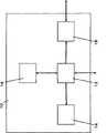
发送机/接收机20包括分组发送电路200、网络接口电路400和分组接收电路300。分组发送电路200经由网络30将分组发送到另一节点10的发送机/接收机20。分组接收电路300经由网络30从另一节点10的发送机/接收机20接收分组。网络接口电路400将分组发送到节点10,并且从节点10接收分组。 The transmitter/
在本实施例中,为了增加传送分组的速度,采用直通传送(cut-through transfer)。在直通传送中,分组被划分为微片(flit)。以如此划分的微片为单位来传送分组。发送机/接收机20依次接收微片。当完全获取分组的头部时,发送机/接收机20参照有关的头部来获取关于分组将要被传送到的目的地的信息。然后,发送机/接收机20开始将分组传送到分组的目的地。 In this embodiment, in order to increase the speed of transmitting packets, cut-through transfer is adopted. In cut-through transfer, packets are divided into flits. Packets are transmitted in units of flits thus divided. The sender/
图2示出节点10的结构的示例。节点10具有系统控制单元12、中央处理单元(CPU)14、存储器16和输入/输出(I/O)接口18。CPU 14执行数据处理。存储器16在其中存储数据。系统控制单元12连接到发送机/接收机20,以利用发送机/接收机20执行分组发送或接收。I/O接口18用于与其它设备的连接。 FIG. 2 shows an example of the structure of the
图3示出该本实施例中待发送或待接收的分组500的分组格式。在分组通信系统中,首先,待发送或待接收的数据被划分为小的数据片,称为分组。接下来,从源的节点到目的地的节点传送分组。 FIG. 3 shows the packet format of a
分组500具有头部差错校验码502、头部504、数据506和分组差错校验码508。头部差错校验码502是其中插入了通过本实施例的方法所生成的序列号的差错校验码。头部差错校验码502用于校验头部中的差错。头部504具有例如分组的源地址、分组的接收方地址(address of the sink)、分组类型和分组长度的信息。数据506包括给定的信息。分组差错校验码508用于校验数据506中的差错。分组500的各个字段的长度例如是如下。头部差错校验码502具有2字节的长度,头部504具有5字节的长度,数据506具有以8字节为单位而变化的可变长度,并且分组差错校验码508具有4字节的长度。
此外,在本实施例中,将指示分组的头部的STP码添加到分组500的开头的8字节字段。将指示分组末尾的END(末尾)码添加到分组的末尾的8字节字段。将指示正常分组的END信息或指示包括差错的分组的EDB信息写入END码。接收电路302参照END码来检测分组的末尾,并且判断分组是否为正常分组。 Also, in the present embodiment, an STP code indicating the head of the packet is added to the 8-byte field at the head of the
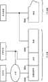
图4示出根据本实施例的分组发送电路200的结构。分组发送电路200包括发送电路202、头部差错校验码生成电路204、分组差错校验码生成电路203和发送序列号控制电路207。 FIG. 4 shows the structure of the
如参照图1所描述的,头部和数据经由网络接口电路400被输入到分组发送电路200。发送序列号控制电路207具有用于存储接下来待发送的分组的序列号的第一发送计数器205和用于存储接收侧可以正常接收的分组的序列号的第二发送计数器206,以便管理待发送的分组的序列号。当分组发送电路200发送分组时,第一发送计数器205递增。第二发送计数器206递增到分组接收电路300可以正常接收的分组的序列号。 As described with reference to FIG. 1 , the header and data are input to the
头部差错校验码生成电路204根据从网络接口电路400输入到分组发送电路200的头部以及由第一发送计数器205指示的序列号来生成头部差错校验码。分组差错校验码生成电路203根据从网络接口电路400输入到分组发送电路200的数据生成分组差错校验码。可以在头部差错校验码生成电路204和分组差错校验码生成电路203中使用给定的算法,例如CRC(循环冗余校验)算法,作为用于生成每个差错校验码的算法。发送电路202根据分组格式经由网络30将由头部差错校验码生成电路204生成的头部差错校验码、头部、数据和由分组差错校验码生成电路203生成的分组差错校验码发送到目的地的节点。 The header error check
将参照图5描述分组发送处理。在步骤S101,发送电路202接收头 部和数据。然后,处理进入到步骤S102。 Packet transmission processing will be described with reference to FIG. 5 . In step S101, the sending
在步骤S102,头部差错校验码生成电路204根据由第一发送计数器205指示的序列号以及由发送电路202接收到的头部来生成头部差错校验码。然后,处理进入到步骤S103。 In step S102 , the header error check
在步骤S103,分组差错校验码生成电路203根据由发送电路202接收到的数据生成分组差错校验码。然后,处理进入到步骤S104。 In step S103 , the packet error check
在步骤S104,发送电路202根据分组格式将头部差错校验码、头部、数据和分组差错校验码发送到网络30。这样,完成处理。 In step S104, the
图6是示出本实施例中生成头部差错校验码的方法的概念性示图。如图6所示,通过使用序列号和分组头部信息进行计算而生成本实施例中的头部差错校验码。 FIG. 6 is a conceptual diagram showing a method of generating a header error check code in the present embodiment. As shown in FIG. 6, the header error check code in this embodiment is generated by calculation using the sequence number and packet header information. the
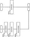
图7示出本实施例中的分组接收电路300的结构。分组接收电路300包括接收电路302、缓冲器304、头部差错校验码生成电路204、分组差错校验码生成电路203、接收序列号控制电路308、头部差错校验码比较电路310、分组差错校验码比较电路306和重传控制电路312。 FIG. 7 shows the structure of the
从分组发送电路200发送的分组经由网络30被输入到分组接收电路300。接收电路302接收分组,并且将接收到的分组输出到缓冲器304。接收电路302还将接收到的分组的头部输出到头部差错校验码生成电路204,将接收到的分组的头部差错校验码输出到头部差错校验码比较电路310,将接收到的分组的数据输出到分组差错校验码生成电路203,并且将接收到的分组的分组差错校验码输出到分组差错校验码比较电路306。 Packets transmitted from the
缓冲器304在其中存储从接收电路302输入的分组。接收序列号控制电路308具有接收计数器305,以管理接收到的分组的序列号。在接收计数器的初始状态下,接收计数器305指示与由第一发送计数器205指示的值相同的值。 The
头部差错校验码生成电路204根据从接收电路302输入的头部以及由接收计数器305指示的序列号来生成头部差错校验码。 The header error check
分组差错校验码生成电路203根据从接收电路302输入的数据生成分组差错校验码。可以在头部差错校验码生成电路204和分组差错校验码生成电路203中使用给定算法,例如CRC算法,作为用于生成每个差错校验码的算法。 The packet error check
头部差错校验码生成电路204将生成的头部差错校验码输出到头部差错校验码比较电路310。头部差错校验码比较电路310对从接收电路302输入的头部差错校验码和从头部差错校验码生成电路204输入的头部差错校验码进行比较。作为比较的结果,在从接收电路302输入的头部差错校验码与从头部差错校验码生成电路204输入的头部差错校验码相匹配的情况下,头部差错校验码比较电路310将指示这些码的匹配的信号输出到缓冲器304和接收序列号控制电路308。此外,在此情况下,也就是说,当这些头部差错校验码彼此匹配时,头部差错校验码比较电路310将指示已经接收到正常分组的ACK分组发送到发送该分组的源的节点10的发送机/接收机20的发送序列号控制电路207。 The header error check
当指示这些码的匹配的信号从头部差错校验码比较电路310被输入到接收序列号控制电路308时,接收计数器305递增。此外,当发送序列号控制电路207接收到ACK分组时,第二发送计数器206递增到ACK分组中的序列号。在正常发送/接收分组的情况下,当发送分组时,第一发送计数器205递增,而当接收分组时,接收计数器305递增。因此,第一发送计数器206指示与由接收计数器305指示的值相同的值。 When a signal indicating a match of these codes is input from the header error check
另一方面,作为这些码的比较结果,在从接收电路302输入的头部差错校验码与从头部差错校验码生成电路204输入的头部差错校验码不匹配的情况下,头部差错校验码比较电路310将指示这些码的不匹配的信号输出到重传控制电路312。重传控制电路312接收该信号,并且将指示不能接收正常分组的NAK分组发送到源的节点10的发送机/接收机20的发送序列号控制电路207。当发送序列号控制电路207接收到NAK分组时,第二发送计数器206递增到NAK分组中正常接收到的分组的序列号。发送电路202执行这样的处理:重传在由第二发送计数器206指示的“序列号+1”的分组之后到来的、由第一发送计数器205指示的序列号的分组。 On the other hand, when the header error check code input from the receiving
例如,在以下情况下请求分组的重传:在有关的分组的头部中检测到误比特的情况下、分组的头部的序列号与分组接收电路300所期望的序列号不匹配的情况下、序列号中未发现误比特但先前的分组丢失的情况下、序列号中发现误比特的情况下以及分组的数据主体中发现误比特的情况下。此外,不仅在在分组主体的数据中发现误比特的情况下请求分组重传,而且还在在头部中发现误比特以及序列号是不连续的情况下请求分组重传。 For example, retransmission of a packet is requested when a bit error is detected in the header of the packet concerned, or when the sequence number of the header of the packet does not match the sequence number expected by the
分组差错校验码生成电路203将生成的分组差错校验码输出到分组 差错校验码比较电路306。然后,分组差错校验码比较电路306对从接收电路302输入的分组差错校验码与从分组差错校验码生成电路203输入的分组差错校验码进行比较。作为比较结果,在从接收电路302输入的分组差错校验码与从分组差错校验码生成电路203输入的分组差错校验码相匹配的情况下,电路306将指示这些码的匹配的信号输出到缓冲器304。另一方面,作为比较结果,在从接收电路302输入的分组差错校验码与从分组差错校验码生成电路203输入的分组差错校验码不匹配的情况下,将指示这些码不匹配的信号输出到缓冲器304。当该信号被输入到缓冲器304时,删除缓冲器304中存储的分组。 The packet error check
在由分组差错校验码生成电路203生成的分组差错校验码与由接收电路302接收到的分组的分组差错校验码的比特反转后的码不匹配的情况下,分组差错校验码比较电路306将指示这些码的不匹配的信号输出到连接至待向其发送分组的目的地的节点10的发送机/接收机20的分组发送电路200。 When the packet error check code generated by the packet error check
连接至分组的目的地的节点10的发送机/接收机20的发送电路202接收该信号,并且将指示分组中包括差错的EDB写入分组的END码。此外,当接收到该信号时,发送电路202要求分组差错校验码生成电路203生成通过对正常分组的分组差错校验码进行比特反转所获得的分组差错校验码。然后,发送电路202将其中EDB被写入END码并且对其添加了通过对正常码的差错校验码进行比特反转所获得的分组差错校验码的分组发送到网络。因此,接收电路302可以检测分组的末尾,并且参照END码来判断接收到的分组是否正常。接收电路302还可以通过判断是否对接收到的分组的分组差错校验码进行了比特反转来判断是否要使得分组无效。 The
在直通传送中,即使在传送期间在分组中发现差错,也不能取消分组的传送。因此,有必要向分组的目的地的节点10通知当前正传送的分组中包括差错。为了提供出现差错的通知,将EDB写入包括差错的分组的END码,并且对差错校验码进行比特反转。 In cut-through transfer, even if an error is found in the packet during transfer, the transfer of the packet cannot be canceled. Therefore, it is necessary to notify the
将参照图8A和图8B描述分组接收处理。在步骤S201,头部差错校验码生成电路204和分组差错校验码生成电路203分别生成头部差错校验码和分组差错校验码。然后,处理进入到步骤S202。 Packet reception processing will be described with reference to FIGS. 8A and 8B . In step S201, the header error check
在步骤S202,接收电路302判断是否已经将END码添加到有关的分组的末尾。当已经将END码添加到分组的末尾时,处理进入到步骤S203。 而当没有将END码添加到分组的末尾时,处理进入到步骤S207。 In step S202, the receiving
在步骤S203,头部差错校验码比较电路310和分组差错校验码比较电路306中的每个判断在步骤S201生成的差错校验码与接收到的分组的差错校验码是否匹配。当所生成的差错校验码与接收到的分组的差错校验码相匹配时,处理进入到步骤S204。而当所生成的差错校验码与接收到的分组的差错校验码不匹配时,处理进入到步骤S209。在步骤S209,删除缓冲器304中存储的分组。 In step S203, each of the header error check
在步骤S204,头部差错校验码比较电路310将指示这些差错校验码的匹配的信号输出到序列号控制电路308。然后,接收计数器305递增,并且处理进入到步骤S205。 In step S204 , the header error check
在步骤S205,头部差错校验码比较电路310将指示已经接收到正常分组的ACK分组发送到分组发送电路200的序列号控制电路207。当序列号控制电路207已接收到ACK分组时,第二发送计数器206递增。然后,处理进入到步骤S206。 In step S205 , the header error check
在步骤S206,缓冲器304输出头部和数据。这样,完成处理。 In step S206, the
将描述当流程从步骤S202进入到步骤S207时执行的处理。在步骤S207,分组差错校验码比较电路306判断由分组差错校验码生成电路203生成的分组差错校验码与由接收电路302接收到的分组的分组差错校验码的比特反转后的码是否匹配。当所生成的分组差错校验码与接收到的分组差错校验码的比特反转后的码相匹配时,由接收电路302接收到的分组是无效的分组。因此,处理进入到步骤S208。另一方面,当所生成的分组差错校验码与接收到的分组差错校验码的比特反转后的码不匹配时,处理进入到步骤S209。 Processing performed when the flow advances from step S202 to step S207 will be described. In step S207, the packet error check
在步骤S208,删除缓冲器304中存储的无效分组。然后,处理进入到步骤S210。 In step S208, invalid packets stored in the
在步骤S210,头部差错校验码比较电路310命令重传控制电路312重传分组。重传控制电路312从头部差错校验码比较电路310接收命令,并且将指示不能接收正常分组的NAK分组发送到分组发送电路200,以请求分组发送电路200重传分组。这样,完成处理。 In step S210, the header error check
图9是示出本实施例中的头部差错和序列号校验方法的概念性示图。从接收电路中保存的序列号和接收到的分组的头部生成本实施例中所使用的头部差错校验码。然后,对所生成的头部差错校验码与接收到的头部 差错校验码进行比较。当序列号彼此不匹配以及在分组的头部中发现差错时,这两个差错校验码彼此不匹配。 FIG. 9 is a conceptual diagram showing a header error and sequence number checking method in this embodiment. The header error check code used in this embodiment is generated from the sequence number held in the receiving circuit and the header of the received packet. Then, the generated header error check code is compared with the received header error check code. These two error check codes do not match each other when the sequence numbers do not match each other and when an error is found in the header of the packet. the
在直通传送中,除非完整地获取头部不能开始传送分组。因此,有时候出现这样的情况:取决于有关的头部的数据量,接收到的微片中可能没有完整地包括头部。如果接收到的微片中没有完整地包括头部,则应该等待直到接收到下一微片来完整地获取头部,并且因此,分组传送的开始将被延迟对应于直到接收到下一微片时所需的等待时间段的量。另一方面,根据本实施例,在头部中不包括序列号。因此,可以减少头部的数据量,并且因此可以增加接收到的微片中可以包括头部的概率。 In cut-through transfers, packets cannot begin to be transferred unless the headers are fully retrieved. Therefore, it sometimes happens that the header may not be completely included in the received flits, depending on the data volume of the header concerned. If the header is not completely included in the received flit, the header should be completely fetched by waiting until the next flit is received, and thus, the start of the packet transfer will be delayed corresponding to until the next flit is received The amount of waiting time period required. On the other hand, according to the present embodiment, the serial number is not included in the header. Therefore, the data amount of the header can be reduced, and thus the probability that the header can be included in the received flit can be increased. the
第二实施例: The second embodiment:
图10示出本实施例中待发送或待接收的分组500的分组格式。分组500包括头部504、数据506和分组差错校验码508。头部504具有例如从其发送分组的源的地址、向其发送分组的接收器的地址、分组类型和分组长度的信息。 FIG. 10 shows the packet format of a
图11示出根据本实施例的分组发送电路200的结构。分组发送电路200包括发送电路202、分组差错校验码生成电路314和发送序列号控制电路207。发送序列号控制电路207具有:第一发送计数器205,用于管理接下来待发送的分组的序列号;以及第二发送计数器206,用于管理接收方可以正常接收的分组的序列号。 FIG. 11 shows the structure of the
接下来,将参照图12描述分组发送处理。在步骤S301,发送电路202接收从节点10发送的头部和数据。处理进入到步骤S302。 Next, packet transmission processing will be described with reference to FIG. 12 . In step S301 , the
在步骤S302,分组差错校验码生成电路314根据由第一发送计数器205指示的序列号和由发送电路202接收到的头部和数据来生成头部差错校验码。可以使用给定算法,例如CRC算法,作为用于由分组差错校验码生成电路314生成分组差错校验码的算法。处理进入到步骤S303。 In step S302 , the packet error check
在步骤S303,发送电路202根据分组格式将分组差错校验码、头部和数据发送到网络30,通过该步骤完成处理。 In step S303, the sending
图13示出根据本实施例的分组接收电路300的结构。分组接收电路300包括接收电路302、缓冲器304、分组差错校验码生成电路314、序列号控制电路308、分组差错校验码比较电路316和重传控制电路312。序列号控制电路308具有接收计数器305。 FIG. 13 shows the configuration of the
接下来,将参照图14A和图14B描述分组接收处理。在步骤S401, 分组差错校验码生成电路314生成分组差错校验码。处理进入到步骤S402。 Next, packet reception processing will be described with reference to FIGS. 14A and 14B . In step S401, the packet error check
在步骤S402,接收电路302判断是否已经将END码添加到分组的末尾。当已经将END码添加到分组的末尾时,处理进入到步骤S403。而当没有将END码添加到分组的末尾时,处理进入到步骤S407。 In step S402, the
在步骤S403,分组差错校验码比较电路316判断在步骤S401生成的分组差错校验码与接收到的分组的分组差错校验码是否匹配。当所生成的分组差错校验码与接收到的分组的分组差错校验码相匹配时,处理进入到步骤S404。而当所生成的分组差错校验码与接收到的分组的分组差错校验码不匹配时,处理进入到步骤S409。在步骤S409,删除缓冲器304中存储的分组。 In step S403, the packet error check code comparison circuit 316 judges whether the packet error check code generated in step S401 matches the packet error check code of the received packet. When the generated packet error check code matches that of the received packet, the process proceeds to step S404. Whereas, when the generated packet error check code does not match the packet error check code of the received packet, the process proceeds to step S409. In step S409, the packets stored in the
在步骤S404,分组差错校验码比较电路316将指示这些分组差错校验码彼此匹配的信号输出到序列号控制电路308。这样,接收计数器305递增,并且处理进入到步骤S405。 In step S404, the packet error check code comparison circuit 316 outputs a signal indicating that the packet error check codes match each other to the sequence
在步骤S405,分组差错校验码比较电路316将指示已经接收到正常分组的ACK分组发送到分组发送电路200的序列号控制电路207。当序列号控制电路207接收到ACK分组时,第二发送计数器206递增,并且处理进入到步骤S406。 In step S405 , the packet error check code comparison circuit 316 transmits an ACK packet indicating that a normal packet has been received to the sequence
在步骤S406,缓冲器304输出头部和数据,通过该步骤完成处理。 In step S406, the
接下来,将描述当流程从步骤S402进入到步骤S407时执行的处理。在步骤S407,分组差错校验码比较电路316判断由分组差错校验码生成电路314生成的分组差错校验码与由接收电路302接收到的分组的分组差错校验码的比特反转后的码是否匹配。当所生成的分组差错校验码与接收到的分组的分组差错校验码的比特反转后的码相匹配时,由接收电路302接收到的分组是无效的分组,并且因此处理进入到步骤S408。而当所生成的分组差错校验码与接收到的分组的分组差错校验码的比特反转后的码不匹配时,处理进入到步骤S409。 Next, the processing performed when the flow advances from step S402 to step S407 will be described. In step S407, the packet error check code comparison circuit 316 judges the packet error check code generated by the packet error check
在步骤S408,删除缓冲器304中存储的无效分组。然后,处理进入到步骤S410。 In step S408, invalid packets stored in the
在步骤S410,分组差错校验码比较电路316命令重传控制电路312重传分组。重传控制电路312从分组差错校验码比较电路316接收命令。重传控制电路312将指示不能接收到正常分组的NAK分组发送到分组发 送电路200,以请求分组发送电路200重传分组,通过该步骤完成处理。 In step S410, the packet error check code comparison circuit 316 instructs the
图15示出待发送或待接收的数据与分组结构之间的对应关系。如图15所示,分组是其中将被称为头部的信息添加到每一划分数据的数据。在图15所示的分组中,在头部中包括序列号。在本实施例中的发送/接收电路中,执行控制,使得从发送电路发送的分组的序列号与由接收电路接收到的分组的序列号相匹配。因此,如果通过使用分别由发送电路和接收电路管理的序列号来生成差错校验码,则在分组中将不需要包括序列号。结果,可以实现发送/接收的通信带宽的有效利用。 FIG. 15 shows the correspondence between data to be transmitted or received and a packet structure. As shown in FIG. 15 , a packet is data in which information called a header is added to each divided data. In the packet shown in FIG. 15, a sequence number is included in the header. In the transmission/reception circuit in this embodiment, control is performed so that the sequence number of the packet transmitted from the transmission circuit matches the sequence number of the packet received by the reception circuit. Therefore, if the error check code is generated by using the sequence numbers respectively managed by the transmission circuit and the reception circuit, it will not be necessary to include the sequence number in the packet. As a result, efficient use of communication bandwidth for transmission/reception can be achieved. the
如上所述,为了更好地理解本发明实施例,已经对其进行了具体地描述,但以上描述并不限制本发明的其它方面。因此,在不脱离本发明主旨和范围的情况下,可以通过各种方式对其进行改动和修改。 As mentioned above, in order to better understand the embodiments of the present invention, the embodiments of the present invention have been specifically described, but the above descriptions do not limit other aspects of the present invention. Therefore, it can be changed and modified in various ways without departing from the spirit and scope of the present invention. the
在此陈述的所有示例和条件语言是为了教导的目的,以帮助读者理解本发明和发明人对促进现有技术所贡献的想法,并且应该理解为不限制于这些具体陈述的示例和条件,说明书中的这些示例的组织也不涉及表示本发明的优势和劣势。虽然已经详细描述了本发明实施例,但应该理解,在不脱离本发明的精神和范围的情况下,可以对其进行各种改变、替代和改动。 All examples and conditional language set forth herein are for teaching purposes to assist the reader in understanding the invention and the inventor's contribution to advance the state of the art, and should be understood not to be limiting to such specifically stated examples and conditions, the specification The organization of these examples is also not meant to illustrate the advantages and disadvantages of the invention. Although the embodiments of the present invention have been described in detail, it should be understood that the various changes, substitutions and alterations could be made hereto without departing from the spirit and scope of the invention. the
Claims (6)
Translated fromChineseApplications Claiming Priority (3)
| Application Number | Priority Date | Filing Date | Title |
|---|---|---|---|
| JP2008-170487 | 2008-06-30 | ||
| JP2008170487 | 2008-06-30 | ||
| JP2008170487AJP4985565B2 (en) | 2008-06-30 | 2008-06-30 | Transmission / reception circuit, reception circuit, and control method for transmission / reception circuit |
Publications (2)
| Publication Number | Publication Date |
|---|---|
| CN101621471A CN101621471A (en) | 2010-01-06 |
| CN101621471Btrue CN101621471B (en) | 2013-05-08 |
Family
ID=41060009
Family Applications (1)
| Application Number | Title | Priority Date | Filing Date |
|---|---|---|---|
| CN2009101463993AExpired - Fee RelatedCN101621471B (en) | 2008-06-30 | 2009-06-26 | System for transmitting and receiving packets |
Country Status (5)
| Country | Link |
|---|---|
| US (1) | US8255560B2 (en) |
| EP (1) | EP2141849A3 (en) |
| JP (1) | JP4985565B2 (en) |
| KR (1) | KR20100003227A (en) |
| CN (1) | CN101621471B (en) |
Families Citing this family (21)
| Publication number | Priority date | Publication date | Assignee | Title |
|---|---|---|---|---|
| US8683095B1 (en) | 2010-06-02 | 2014-03-25 | Marvell International Ltd | Packet identification tracker |
| US9391671B2 (en)* | 2011-05-06 | 2016-07-12 | Samsung Electronics Co., Ltd. | Wireless power transmission and charging system and method thereof |
| US8838999B1 (en) | 2011-05-17 | 2014-09-16 | Applied Micro Circuits Corporation | Cut-through packet stream encryption/decryption |
| CN102255713B (en)* | 2011-07-24 | 2013-10-30 | 哈尔滨工程大学 | Data packets of underwater sound sensor network and transmission method |
| JP2013068105A (en) | 2011-09-21 | 2013-04-18 | Hitachi Automotive Systems Ltd | Electronic control device for vehicle |
| JP5842519B2 (en)* | 2011-09-30 | 2016-01-13 | 日本電気株式会社 | COMMUNICATION SYSTEM, DATA TRANSMITTING APPARATUS, DATA RECEIVING APPARATUS, PACKET REMISSION CONTROL METHOD, PACKET RETRANSMISSION CONTROL PROGRAM |
| IN2014MN01023A (en)* | 2011-12-08 | 2015-05-01 | Qualcomm Technologies Inc | |
| CN103188059A (en)* | 2011-12-28 | 2013-07-03 | 华为技术有限公司 | Method, device and system for data packet retransmission in quick path interconnect system |
| US10044469B2 (en) | 2012-03-02 | 2018-08-07 | Lsis Co., Ltd. | Communication device and communication method |
| ES2590148T3 (en)* | 2012-03-02 | 2016-11-18 | Lsis Co., Ltd. | Communication device and communication procedure |
| JP6193896B2 (en)* | 2012-03-02 | 2017-09-06 | エルエス産電株式会社Lsis Co., Ltd. | Communication apparatus and communication method |
| US9075736B2 (en) | 2013-01-07 | 2015-07-07 | Qualcomm Incorporated | Additional error protection for wireless transmission |
| US9201722B1 (en)* | 2014-07-10 | 2015-12-01 | Freescale Semiconductor, Inc. | System-on-chip and method for sending data in a system-on-chip |
| JP5813833B2 (en)* | 2014-07-15 | 2015-11-17 | 日立オートモティブシステムズ株式会社 | Electronic control unit for automobile |
| US9749448B2 (en)* | 2014-11-25 | 2017-08-29 | Intel Corporation | Header parity error handling |
| JP2017063273A (en)* | 2015-09-24 | 2017-03-30 | 富士通株式会社 | Transmission apparatus and transmission system |
| EP3166246B1 (en)* | 2015-11-06 | 2018-06-20 | Fts Computertechnik Gmbh | Method to detect and to handle failures in the communication in a computer network |
| US10791062B1 (en)* | 2017-11-14 | 2020-09-29 | Amazon Technologies, Inc. | Independent buffer memory for network element |
| EP3565186B1 (en)* | 2018-05-02 | 2021-06-30 | TTTech Computertechnik AG | Device and network to reliably communicate in a network |
| WO2022014089A1 (en)* | 2020-07-16 | 2022-01-20 | 富士フイルム株式会社 | Ultrasonic system and method for controlling ultrasonic system |
| CN114884622A (en)* | 2022-05-23 | 2022-08-09 | 海光信息技术股份有限公司 | Data transmission method and related device |
Citations (3)
| Publication number | Priority date | Publication date | Assignee | Title |
|---|---|---|---|---|
| JP3323484B2 (en)* | 2000-09-12 | 2002-09-09 | 松下電器産業株式会社 | Packet transmitting device, packet receiving device, and packet transmission method |
| US6931581B1 (en)* | 2000-10-25 | 2005-08-16 | Sun Microsystems, Inc. | Method for superimposing a sequence number in an error detection code in a data network |
| CN101069377A (en)* | 2005-01-18 | 2007-11-07 | 株式会社东芝 | Wireless communication system, wireless transmitting equipment and wireless receiving equipment |
Family Cites Families (13)
| Publication number | Priority date | Publication date | Assignee | Title |
|---|---|---|---|---|
| JPH05336149A (en)* | 1992-05-28 | 1993-12-17 | Nec Corp | Bit error/missing cell detection system in atm communication |
| US5953418A (en)* | 1995-06-14 | 1999-09-14 | David Hall | Providing selective data broadcast receiver addressability |
| JPH09162873A (en)* | 1995-12-05 | 1997-06-20 | Nippon Telegr & Teleph Corp <Ntt> | Error detection method and device |
| US6088337A (en)* | 1997-10-20 | 2000-07-11 | Motorola, Inc. | Method access point device and peripheral for providing space diversity in a time division duplex wireless system |
| US6754231B1 (en)* | 1999-06-18 | 2004-06-22 | Telefonaktiebolaget Lm Ericsson (Publ) | Robust header compression in packet communications |
| US7126950B2 (en)* | 2000-02-14 | 2006-10-24 | Nec Corporation | Method and system for transmission and reception of asynchronously multiplexed signals |
| JP3730835B2 (en)* | 2000-03-03 | 2006-01-05 | 株式会社エヌ・ティ・ティ・ドコモ | Packet transmission method, relay device, and data terminal |
| JP4520032B2 (en)* | 2000-08-17 | 2010-08-04 | パナソニック株式会社 | Header compression apparatus and header compression method |
| JP2002094553A (en)* | 2000-09-12 | 2002-03-29 | Matsushita Electric Ind Co Ltd | Packet transmission device and packet transmission method |
| US6684363B1 (en)* | 2000-10-25 | 2004-01-27 | Sun Microsystems, Inc. | Method for detecting errors on parallel links |
| JP3600189B2 (en)* | 2001-06-19 | 2004-12-08 | 松下電器産業株式会社 | Packet transmitting / receiving apparatus and packet transmitting method |
| US20030066016A1 (en) | 2001-09-28 | 2003-04-03 | Eric Wehage | Methodology for detecting lost packets |
| US20080195912A1 (en)* | 2007-02-14 | 2008-08-14 | Nokia Corporation | Method of communicatoin |
- 2008
- 2008-06-30JPJP2008170487Apatent/JP4985565B2/ennot_activeExpired - Fee Related
- 2009
- 2009-06-16USUS12/485,529patent/US8255560B2/ennot_activeExpired - Fee Related
- 2009-06-23EPEP20090163526patent/EP2141849A3/ennot_activeWithdrawn
- 2009-06-26CNCN2009101463993Apatent/CN101621471B/ennot_activeExpired - Fee Related
- 2009-06-29KRKR20090058261Apatent/KR20100003227A/ennot_activeCeased
Patent Citations (3)
| Publication number | Priority date | Publication date | Assignee | Title |
|---|---|---|---|---|
| JP3323484B2 (en)* | 2000-09-12 | 2002-09-09 | 松下電器産業株式会社 | Packet transmitting device, packet receiving device, and packet transmission method |
| US6931581B1 (en)* | 2000-10-25 | 2005-08-16 | Sun Microsystems, Inc. | Method for superimposing a sequence number in an error detection code in a data network |
| CN101069377A (en)* | 2005-01-18 | 2007-11-07 | 株式会社东芝 | Wireless communication system, wireless transmitting equipment and wireless receiving equipment |
Non-Patent Citations (1)
| Title |
|---|
| JP特許3323484B2 2002.09.09 |
Also Published As
| Publication number | Publication date |
|---|---|
| EP2141849A3 (en) | 2013-12-18 |
| US20090327826A1 (en) | 2009-12-31 |
| KR20100003227A (en) | 2010-01-07 |
| EP2141849A2 (en) | 2010-01-06 |
| CN101621471A (en) | 2010-01-06 |
| JP4985565B2 (en) | 2012-07-25 |
| JP2010011296A (en) | 2010-01-14 |
| US8255560B2 (en) | 2012-08-28 |
Similar Documents
| Publication | Publication Date | Title |
|---|---|---|
| CN101621471B (en) | System for transmitting and receiving packets | |
| US20080195912A1 (en) | Method of communicatoin | |
| CN101764730B (en) | CAN bus data transmission method | |
| KR101283482B1 (en) | Apparatus for processing pci express protocol | |
| WO2011046056A1 (en) | Transmission control method for packet communication and packet communication system | |
| CN103004124B (en) | Communication Interfaces and Protocols | |
| CN104038327B (en) | Error retransmission method for FC (fiber channel) network | |
| CN103368703B (en) | Data package retransmission method, data packet receiving method and device | |
| CN115777184A (en) | A data retransmission method and device | |
| CN110299973B (en) | Receiving method and device for data rolling transmission | |
| US7047437B2 (en) | Method and system for detecting dropped micro-packets | |
| CN109039552A (en) | A kind of data reconstruction method and device | |
| CN110299971B (en) | Data message receiving method and device | |
| CN110299970B (en) | Data message sending method and device | |
| US7653060B2 (en) | System and method for implementing ASI over long distances | |
| US20080107116A1 (en) | Large scale multi-processor system with a link-level interconnect providing in-order packet delivery | |
| CN114095117A (en) | Retransmission method and related device for Ethernet error frame | |
| CN110299969B (en) | Method and device for transmitting data in rolling mode | |
| US20230269062A1 (en) | Communication apparatus and communication system | |
| CN117579226B (en) | A link retransmission method and device based on IB flow control packet | |
| CN116685952A (en) | A data transmission method and device | |
| CN103229159A (en) | Smart aging retry buffer | |
| JP2002261737A (en) | Transmission data loss detection system | |
| Bansal et al. | Analysis of Sliding Window Protocol for Connected Node | |
| WO2015051736A1 (en) | Fault tolerant method for packet transmission of network node and network node |
Legal Events
| Date | Code | Title | Description |
|---|---|---|---|
| C06 | Publication | ||
| PB01 | Publication | ||
| C10 | Entry into substantive examination | ||
| SE01 | Entry into force of request for substantive examination | ||
| C14 | Grant of patent or utility model | ||
| GR01 | Patent grant | ||
| CF01 | Termination of patent right due to non-payment of annual fee | ||
| CF01 | Termination of patent right due to non-payment of annual fee | Granted publication date:20130508 Termination date:20180626 |