CN101615376A - Display device - Google Patents
Display deviceDownload PDFInfo
- Publication number
- CN101615376A CN101615376ACN200910150872ACN200910150872ACN101615376ACN 101615376 ACN101615376 ACN 101615376ACN 200910150872 ACN200910150872 ACN 200910150872ACN 200910150872 ACN200910150872 ACN 200910150872ACN 101615376 ACN101615376 ACN 101615376A
- Authority
- CN
- China
- Prior art keywords
- period
- potential
- threshold
- transistor
- threshold value
- Prior art date
- Legal status (The legal status is an assumption and is not a legal conclusion. Google has not performed a legal analysis and makes no representation as to the accuracy of the status listed.)
- Granted
Links
Images


Classifications
- G—PHYSICS
- G09—EDUCATION; CRYPTOGRAPHY; DISPLAY; ADVERTISING; SEALS
- G09G—ARRANGEMENTS OR CIRCUITS FOR CONTROL OF INDICATING DEVICES USING STATIC MEANS TO PRESENT VARIABLE INFORMATION
- G09G3/00—Control arrangements or circuits, of interest only in connection with visual indicators other than cathode-ray tubes
- G09G3/20—Control arrangements or circuits, of interest only in connection with visual indicators other than cathode-ray tubes for presentation of an assembly of a number of characters, e.g. a page, by composing the assembly by combination of individual elements arranged in a matrix no fixed position being assigned to or needed to be assigned to the individual characters or partial characters
- G09G3/22—Control arrangements or circuits, of interest only in connection with visual indicators other than cathode-ray tubes for presentation of an assembly of a number of characters, e.g. a page, by composing the assembly by combination of individual elements arranged in a matrix no fixed position being assigned to or needed to be assigned to the individual characters or partial characters using controlled light sources
- G09G3/30—Control arrangements or circuits, of interest only in connection with visual indicators other than cathode-ray tubes for presentation of an assembly of a number of characters, e.g. a page, by composing the assembly by combination of individual elements arranged in a matrix no fixed position being assigned to or needed to be assigned to the individual characters or partial characters using controlled light sources using electroluminescent panels
- G09G3/32—Control arrangements or circuits, of interest only in connection with visual indicators other than cathode-ray tubes for presentation of an assembly of a number of characters, e.g. a page, by composing the assembly by combination of individual elements arranged in a matrix no fixed position being assigned to or needed to be assigned to the individual characters or partial characters using controlled light sources using electroluminescent panels semiconductive, e.g. using light-emitting diodes [LED]
- G09G3/3208—Control arrangements or circuits, of interest only in connection with visual indicators other than cathode-ray tubes for presentation of an assembly of a number of characters, e.g. a page, by composing the assembly by combination of individual elements arranged in a matrix no fixed position being assigned to or needed to be assigned to the individual characters or partial characters using controlled light sources using electroluminescent panels semiconductive, e.g. using light-emitting diodes [LED] organic, e.g. using organic light-emitting diodes [OLED]
- G09G3/3225—Control arrangements or circuits, of interest only in connection with visual indicators other than cathode-ray tubes for presentation of an assembly of a number of characters, e.g. a page, by composing the assembly by combination of individual elements arranged in a matrix no fixed position being assigned to or needed to be assigned to the individual characters or partial characters using controlled light sources using electroluminescent panels semiconductive, e.g. using light-emitting diodes [LED] organic, e.g. using organic light-emitting diodes [OLED] using an active matrix
- G09G3/3233—Control arrangements or circuits, of interest only in connection with visual indicators other than cathode-ray tubes for presentation of an assembly of a number of characters, e.g. a page, by composing the assembly by combination of individual elements arranged in a matrix no fixed position being assigned to or needed to be assigned to the individual characters or partial characters using controlled light sources using electroluminescent panels semiconductive, e.g. using light-emitting diodes [LED] organic, e.g. using organic light-emitting diodes [OLED] using an active matrix with pixel circuitry controlling the current through the light-emitting element
- G—PHYSICS
- G09—EDUCATION; CRYPTOGRAPHY; DISPLAY; ADVERTISING; SEALS
- G09G—ARRANGEMENTS OR CIRCUITS FOR CONTROL OF INDICATING DEVICES USING STATIC MEANS TO PRESENT VARIABLE INFORMATION
- G09G2300/00—Aspects of the constitution of display devices
- G09G2300/08—Active matrix structure, i.e. with use of active elements, inclusive of non-linear two terminal elements, in the pixels together with light emitting or modulating elements
- G09G2300/0809—Several active elements per pixel in active matrix panels
- G09G2300/0814—Several active elements per pixel in active matrix panels used for selection purposes, e.g. logical AND for partial update
- G—PHYSICS
- G09—EDUCATION; CRYPTOGRAPHY; DISPLAY; ADVERTISING; SEALS
- G09G—ARRANGEMENTS OR CIRCUITS FOR CONTROL OF INDICATING DEVICES USING STATIC MEANS TO PRESENT VARIABLE INFORMATION
- G09G2300/00—Aspects of the constitution of display devices
- G09G2300/08—Active matrix structure, i.e. with use of active elements, inclusive of non-linear two terminal elements, in the pixels together with light emitting or modulating elements
- G09G2300/0809—Several active elements per pixel in active matrix panels
- G09G2300/0819—Several active elements per pixel in active matrix panels used for counteracting undesired variations, e.g. feedback or autozeroing
- G—PHYSICS
- G09—EDUCATION; CRYPTOGRAPHY; DISPLAY; ADVERTISING; SEALS
- G09G—ARRANGEMENTS OR CIRCUITS FOR CONTROL OF INDICATING DEVICES USING STATIC MEANS TO PRESENT VARIABLE INFORMATION
- G09G2300/00—Aspects of the constitution of display devices
- G09G2300/08—Active matrix structure, i.e. with use of active elements, inclusive of non-linear two terminal elements, in the pixels together with light emitting or modulating elements
- G09G2300/0809—Several active elements per pixel in active matrix panels
- G09G2300/0842—Several active elements per pixel in active matrix panels forming a memory circuit, e.g. a dynamic memory with one capacitor
- G09G2300/0861—Several active elements per pixel in active matrix panels forming a memory circuit, e.g. a dynamic memory with one capacitor with additional control of the display period without amending the charge stored in a pixel memory, e.g. by means of additional select electrodes
- G—PHYSICS
- G09—EDUCATION; CRYPTOGRAPHY; DISPLAY; ADVERTISING; SEALS
- G09G—ARRANGEMENTS OR CIRCUITS FOR CONTROL OF INDICATING DEVICES USING STATIC MEANS TO PRESENT VARIABLE INFORMATION
- G09G2320/00—Control of display operating conditions
- G09G2320/02—Improving the quality of display appearance
- G09G2320/0252—Improving the response speed
- G—PHYSICS
- G09—EDUCATION; CRYPTOGRAPHY; DISPLAY; ADVERTISING; SEALS
- G09G—ARRANGEMENTS OR CIRCUITS FOR CONTROL OF INDICATING DEVICES USING STATIC MEANS TO PRESENT VARIABLE INFORMATION
- G09G2320/00—Control of display operating conditions
- G09G2320/04—Maintaining the quality of display appearance
- G09G2320/043—Preventing or counteracting the effects of ageing
Landscapes
- Engineering & Computer Science (AREA)
- Physics & Mathematics (AREA)
- Computer Hardware Design (AREA)
- General Physics & Mathematics (AREA)
- Theoretical Computer Science (AREA)
- Control Of Indicators Other Than Cathode Ray Tubes (AREA)
- Control Of El Displays (AREA)
- Electroluminescent Light Sources (AREA)
- Devices For Indicating Variable Information By Combining Individual Elements (AREA)
Abstract
Translated fromChinese
Description
Translated fromChinese技术领域technical field
本发明涉及具有像素电路(也称作像素)的显示设备,该像素电路提供有电光元件(也称作显示元件或发光元件),并且具体涉及具有电流驱动型电光元件作为显示元件、并且在每个像素电路中具有有源元件的显示设备,所述电流驱动型电光元件根据驱动信号的大小而改变亮度,通过所述有源元件在像素单元中执行显示驱动。The present invention relates to a display device having a pixel circuit (also referred to as a pixel) provided with an electro-optical element (also referred to as a display element or a light-emitting element), and in particular to an electro-optical element having a current-driven type as a display element and in each A display device having an active element in a pixel circuit, the current-driven electro-optic element changes brightness according to the magnitude of a driving signal, and display driving is performed in a pixel unit through the active element.
背景技术Background technique
存在使用电光元件作为像素的显示元件的显示设备,所述电光元件根据施加到电光元件的电压或流过电光元件的电流而改变亮度。例如,液晶显示元件是根据施加到电光元件的电压改变亮度的电光元件的典型示例,并且有机电致发光(以下称为有机EL)元件(有机发光二极管(OLED))是根据流过电光元件的电流改变亮度的电光元件的典型示例。使用后一有机EL元件的有机EL显示设备是使用自发光电光元件作为像素的显示元件的所谓的发射性显示设备。There is a display device that uses an electro-optical element that changes luminance according to a voltage applied to the electro-optic element or a current flowing through the electro-optical element as a display element of a pixel. For example, a liquid crystal display element is a typical example of an electro-optical element that changes brightness according to a voltage applied to the electro-optic element, and an organic electroluminescence (hereinafter referred to as organic EL) element (organic light-emitting diode (OLED)) is a A typical example of an electro-optic element in which an electric current changes brightness. An organic EL display device using the latter organic EL element is a so-called emissive display device using a self-luminous electro-optical element as a display element of a pixel.
有机EL元件包括有机薄膜(有机层),其通过在下电极和上电极之间层叠有机空穴传输层和有机发光层而形成。有机EL元件是利用在对有机薄膜施加电场时出现的发光现象的电光元件。通过控制流过有机EL元件的电流值获得色彩灰度。An organic EL element includes an organic thin film (organic layer) formed by laminating an organic hole transport layer and an organic light emitting layer between a lower electrode and an upper electrode. An organic EL element is an electro-optic element that utilizes a luminescence phenomenon that occurs when an electric field is applied to an organic thin film. Color gradation is obtained by controlling the value of current flowing through the organic EL element.
有机EL元件可通过相对低的施加电压(例如,10V或更低)而驱动,因此消耗低功率。此外,有机EL元件是自己发光的自发光的元件,因此消除了对于如在液晶显示设备中期望的背光的辅助照明部件的需要。因此,有机EL元件便利了重量和厚度的减少。此外,有机EL元件具有非常高的响应速度(例如,大约几μs),使得在显示运动图像时不出现余像。因为有机EL元件具有这些优点,所以近来已经积极开发了使用有机EL元件作为电光元件的平板发射性显示设备。The organic EL element can be driven by a relatively low applied voltage (for example, 10 V or lower), and thus consumes low power. Furthermore, the organic EL element is a self-luminous element that emits light by itself, thus eliminating the need for an auxiliary lighting part for a backlight as desired in a liquid crystal display device. Therefore, the organic EL element facilitates weight and thickness reduction. In addition, the organic EL element has a very high response speed (for example, about several μs), so that no afterimage occurs when a moving image is displayed. Since organic EL elements have these advantages, recently, flat-panel emissive display devices using organic EL elements as electro-optical elements have been actively developed.
使用电光元件的显示设备包括使用液晶显示元件的液晶显示设备和使用有机EL元件的有机EL显示设备,所述使用电光元件的显示设备可以采用简单(无源)矩阵系统和有源矩阵系统作为显示设备的驱动系统。然而,尽管简单矩阵型显示设备具有简单的结构,但是它存在例如难以实现大和高清晰度显示设备的问题。A display device using an electro-optical element includes a liquid crystal display device using a liquid crystal display element and an organic EL display device using an organic EL element, and the display device using an electro-optical element can adopt a simple (passive) matrix system and an active matrix system as a display The drive system of the device. However, although a simple matrix type display device has a simple structure, it has problems such as difficulty in realizing a large and high-definition display device.
因此,近来已经积极开发了这样的有源矩阵系统,其通过使用在像素内类似提供的有源元件(例如,绝缘栅极场效应晶体管(典型地,薄膜晶体管(TFT)))作为开关晶体管,控制提供到像素内的发光元件的像素信号。Therefore, active matrix systems have been actively developed recently by using active elements such as insulated gate field effect transistors (typically thin film transistors (TFTs)) similarly provided inside pixels as switching transistors, A pixel signal supplied to a light emitting element within a pixel is controlled.
当使得像素电路内的电光元件发光时,经由视频信号线提供的输入图像信号捕获到存储电容器(也称作像素电容)中,其通过开关晶体管(称为采样晶体管)提供到驱动晶体管的栅极端(控制输入端),并且将对应于捕获的输入图像信号的驱动信号提供到电光元件。When the electro-optical element inside the pixel circuit is made to emit light, the input image signal supplied via the video signal line is captured into a storage capacitor (also called pixel capacitance), which is supplied to the gate terminal of the driving transistor through a switching transistor (called sampling transistor) (control input terminal), and supply a drive signal corresponding to the captured input image signal to the electro-optical element.
在利用液晶显示元件作为电光元件的液晶显示设备中,因为液晶显示元件是电压驱动型元件,所以通过对应于捕获到存储电容器中的输入图像信号的电压信号自身驱动液晶显示元件。另一方面,在利用如有机EL元件等的电流驱动型元件作为电光元件的有机EL显示设备中,驱动晶体管将对应于捕获到存储电容器中的输入图像信号的驱动信号(电压信号)转换为电流信号,并且将驱动电流提供到有机EL元件等。In a liquid crystal display device using a liquid crystal display element as an electro-optical element, since the liquid crystal display element is a voltage-driven type element, the liquid crystal display element itself is driven by a voltage signal corresponding to an input image signal captured in a storage capacitor. On the other hand, in an organic EL display device using a current-driven type element such as an organic EL element as an electro-optical element, a drive transistor converts a drive signal (voltage signal) corresponding to an input image signal captured in a storage capacitor into a current signal, and supply a drive current to an organic EL element or the like.
当驱动电流的值变化时,以有机EL元件代表的电流驱动型电光元件在发光亮度上变化。因此,为了使得电光元件以稳定亮度发光,将稳定的驱动电流提供到电光元件是重要的。例如,用于将驱动电流提供到有机EL元件的驱动系统可大致分类为恒流驱动系统和恒压驱动系统(这是公知的技术,因此在此将不呈现公知文献)。A current-driven electro-optical element typified by an organic EL element changes in light emission luminance when the value of the driving current changes. Therefore, in order for the electro-optical element to emit light with stable luminance, it is important to supply a stable drive current to the electro-optical element. For example, a drive system for supplying a drive current to an organic EL element can be roughly classified into a constant current drive system and a constant voltage drive system (this is a well-known technique, so known documents will not be presented here).
因为有机EL元件的电压-电流特性具有陡峭的斜率,所以当执行恒压驱动时,微小的电压变化或元件特性的变化导致极大的电流变化,因此引起极大的亮度变化。因此,通常使用恒流驱动,其中在饱和区使用驱动晶体管。当然,即使利用恒流驱动,电流的改变也引起亮度的变化。然而,小的电流变化仅仅导致小的亮度变化。Since the voltage-current characteristic of an organic EL element has a steep slope, when constant voltage driving is performed, a slight voltage change or a change in element characteristics results in an extremely large current change, thus causing an extremely large luminance change. Therefore, constant current driving is usually used, in which the driving transistor is used in the saturation region. Of course, even with constant current driving, a change in current causes a change in brightness. However, small current changes only result in small brightness changes.
相反,即使利用恒流驱动系统,为了电光元件的发光亮度不变,重要的是,根据输入图像信号写到存储电容器并由存储电容器保持的驱动信号是恒定的。例如,为了有机EL元件的发光亮度不变,重要的是,对应于输入图像信号的驱动电流是恒定的。In contrast, even with a constant current drive system, in order for the light emission luminance of the electro-optical element to be constant, it is important that the drive signal written to and held by the storage capacitor according to an input image signal be constant. For example, in order for the emission luminance of the organic EL element to remain constant, it is important that the drive current corresponding to the input image signal be constant.
然而,由于工艺变化,驱动电光元件的有源元件(驱动晶体管)的阈值电压和迁移率变化。此外,如有机EL元件等的电光元件的特性随时间变化。即使在恒流驱动系统的情况下,这种用于驱动的有源元件的特性的变化和这种电光元件的特性的变化也影响发光亮度。However, the threshold voltage and mobility of active elements (driving transistors) that drive electro-optic elements vary due to process variations. In addition, the characteristics of electro-optical elements such as organic EL elements change with time. Even in the case of a constant current drive system, such variations in characteristics of active elements for driving and variations in characteristics of such electro-optical elements affect light emission luminance.
因此,正在研究用于校正每个像素电路内的用于驱动的有源元件和电光元件的特性的上述变化导致的亮度变化的各种机制,以一致地控制显示设备的整个屏幕上的发光亮度。Therefore, various mechanisms for correcting the luminance variation caused by the above-mentioned variation in the characteristics of the active element for driving and the electro-optical element within each pixel circuit are being studied to uniformly control the emission luminance across the entire screen of the display device .
例如,作为用于有机EL元件的像素电路的、在日本专利公开No.2006-215213(以下称为专利文献1)中描述的机制具有:阈值校正功能,用于即使在存在驱动晶体管的阈值电压的变化或长期改变时,也保持驱动电流恒定;迁移率校正功能,用于即使在存在驱动晶体管的迁移率的变化或长期改变时,也保持驱动电流恒定;以及自举功能,用于即使在存在有机EL元件的电流-电压特性的长期改变时,也保持驱动电流恒定。For example, a mechanism described in Japanese Patent Laid-Open No. 2006-215213 (hereinafter referred to as Patent Document 1) as a pixel circuit for an organic EL element has a threshold value correction function for The drive current is kept constant even when there is a change or long-term change in the mobility of the drive transistor; the mobility correction function is used to keep the drive current constant even when there is a change or long-term change in the mobility of the drive transistor; The drive current is kept constant also in the presence of long-term changes in the current-voltage characteristics of the organic EL element.
在阈值校正操作期间,将预定幅度的电源电压提供到驱动晶体管的电源端,以创建电流在驱动晶体管的漏极和源极之间流动的状态,并且使得采样晶体管导通,其中用于阈值校正的预定大小的参考电势提供到采样晶体管的输入端。During the threshold value correction operation, a power supply voltage of a predetermined magnitude is supplied to the power supply terminal of the drive transistor to create a state where current flows between the drain and source of the drive transistor, and to turn on the sampling transistor, which is used for threshold value correction A reference potential of predetermined magnitude is supplied to the input terminal of the sampling transistor.
在此情况下,依赖于驱动时序,阈值校正操作的时段可能不足,因此对应于驱动晶体管的阈值电压的电压不能完全保持在存储电容器中。用于针对这种现象的措施,考虑采用这样的机制,其通过重复执行多次阈值校正操作,使得存储电容器确定地保持对应于驱动晶体管的阈值电压的电压(参见日本专利公开No.2005-258326)。In this case, depending on the driving timing, the period of the threshold correction operation may be insufficient, and thus the voltage corresponding to the threshold voltage of the driving transistor cannot be completely held in the storage capacitor. For countermeasures against this phenomenon, it is considered to employ a mechanism by which the storage capacitor surely holds a voltage corresponding to the threshold voltage of the drive transistor by repeatedly performing the threshold correction operation a plurality of times (see Japanese Patent Laid-Open No. 2005-258326 ).
发明内容Contents of the invention
然而,在电流保持流过驱动晶体管的同时、执行多次阈值校正操作的情况下,当在各阈值校正操作之间的间隔时段内将采样晶体管设置在不导通状态下时,此时没有完全校正驱动晶体管的阈值电压,因此跨越存储电容器的电压(即,在控制输入端(栅极)和驱动晶体管的电光元件侧上的端子之间的电压)大于阈值电压。However, in the case where a plurality of threshold correction operations are performed while the current keeps flowing through the drive transistor, when the sampling transistor is set in a non-conductive state during the interval period between the respective threshold correction operations, there is no complete The threshold voltage of the drive transistor is corrected so that the voltage across the storage capacitor (ie the voltage between the control input (gate) and the terminal on the electro-optic element side of the drive transistor) is greater than the threshold voltage.
当阈值校正时间短或间隔时段的时间长时,在间隔时段内,驱动晶体管的电光元件侧上的端子的电势极大地上升。结果,在下一阈值校正操作期间,跨越存储电容器的电压变为小于阈值电压,此后,不正常地执行阈值校正操作,这导致显示图像中出现的不均匀性或条纹。When the threshold value correction time is short or the time of the interval period is long, the potential of the terminal on the electro-optical element side of the driving transistor rises greatly within the interval period. As a result, during the next threshold correction operation, the voltage across the storage capacitor becomes smaller than the threshold voltage, and thereafter, the threshold correction operation is not performed normally, which results in unevenness or streaks appearing in the display image.
专利文献1中描述的机制需要用于提供用于校正的电势的布线、用于校正的开关晶体管、以及对开关晶体管进行脉冲驱动的开关脉冲。当包括驱动晶体管和采样晶体管时,在专利文献1中描述的机制采用了5TR驱动配置,使得像素电路的配置是复杂的,具有大量垂直扫描线等。像素电路的许多构成元件妨碍了更高清晰度的显示设备的实现。结果,难以将5TR驱动配置应用到在小电子设备(如便携式设备(移动电话)等)中使用的显示设备。The mechanism described in
因此期望开发一种机制,用于减轻不正常地执行阈值校正操作的问题,同时简化像素电路。此时,还应该考虑防止在5TR驱动配置的情况下不出现的新问题随着扫描线的数量的减少和像素电路的简化而出现。It is therefore desirable to develop a mechanism for alleviating the problem of improperly performing threshold correction operations while simplifying the pixel circuitry. At this time, consideration should also be given to preventing new problems that do not occur in the case of the 5TR drive configuration from appearing with the reduction in the number of scanning lines and the simplification of the pixel circuit.
已经鉴于上述情况做出本发明。期望提供一种机制,即使在采用执行阈值校正操作的机制作为用于抑制由于驱动晶体管的特性变化而导致的亮度变化的机制时,也能减轻不正常执行阈值校正操作的问题。还期望提供一种机制,其通过简化像素电路,实现更高清晰度的显示设备。The present invention has been made in view of the above circumstances. It is desirable to provide a mechanism that can alleviate the problem of abnormally performing threshold correction operations even when a mechanism for performing threshold correction operations is adopted as a mechanism for suppressing changes in luminance due to changes in characteristics of drive transistors. It is also desirable to provide a mechanism that realizes a higher-definition display device by simplifying the pixel circuit.
根据本发明的显示设备的一种形式包括:像素阵列部分,具有以矩阵形式排列的像素电路,所述像素电路的每个包括用于产生驱动电流的驱动晶体管、连接到所述驱动晶体管的输出端的电光元件、用于保持与视频信号的信号幅度对应的信息的存储电容器、以及用于将与所述信号幅度对应的信息写到所述存储电容器的采样晶体管;垂直扫描部分,用于产生用于所述像素电路的垂直扫描的垂直扫描脉冲;水平扫描部分,用于将所述视频信号提供到所述像素电路,以便与所述垂直扫描部分中的所述垂直扫描一致;以及驱动信号恒定实现电路,用于保持所述驱动电流恒定。One form of a display device according to the present invention includes: a pixel array section having pixel circuits arranged in a matrix, each of the pixel circuits including a driving transistor for generating a driving current, an output connected to the driving transistor An electro-optical element at the terminal, a storage capacitor for holding information corresponding to the signal amplitude of the video signal, and a sampling transistor for writing information corresponding to the signal amplitude to the storage capacitor; a vertical scanning section for generating a vertical scanning pulse for vertical scanning of the pixel circuit; a horizontal scanning section for supplying the video signal to the pixel circuit so as to coincide with the vertical scanning in the vertical scanning section; and a driving signal constant A circuit is implemented for keeping the drive current constant.
所述驱动信号恒定实现电路实现阈值校正功能,其通过在所述垂直扫描部分和所述水平扫描部分的控制下,在预定大小的电源电压提供到所述驱动晶体管的电源端、并且预定大小的参考电势提供到所述采样晶体管的输入端的时间段内,使得所述采样晶体管导通,使得所述存储电容器保持与所述驱动晶体管的阈值电压对应的电压。The driving signal constant realization circuit realizes the threshold value correction function by supplying a power supply voltage of a predetermined magnitude to the power supply terminal of the driving transistor under the control of the vertical scanning part and the horizontal scanning part, and a power supply voltage of a predetermined magnitude The sampling transistor is turned on for a period in which a reference potential is supplied to the input terminal of the sampling transistor so that the storage capacitor maintains a voltage corresponding to the threshold voltage of the driving transistor.
此外,作为第一机制,所述驱动信号恒定实现电路在以一个水平扫描时段作为一个处理周期、维持流过所述驱动晶体管的电流的状态下执行阈值校正操作多次,并且执行一个水平时段内的阈值校正分割处理,在所述一个水平时段内的阈值校正分割处理中,在至少一个阈值校正处理时段内,在用于阈值校正的所述参考电势提供到所述采样晶体管的所述输入端的情况下,执行阈值校正处理,同时重复多次采样晶体管的导通和不导通。In addition, as a first mechanism, the drive signal constant realization circuit performs the threshold correction operation a plurality of times in a state of maintaining the current flowing through the drive transistor with one horizontal scan period as one processing cycle, and performs the operation within one horizontal period. In the threshold correction division processing within one horizontal period, during at least one threshold correction processing period, when the reference potential for threshold correction is supplied to the input terminal of the sampling transistor In this case, threshold value correction processing is performed while repeating the conduction and non-conduction of the sampling transistor a plurality of times.
此外,作为第二机制,所述驱动信号恒定实现电路在第一阈值校正处理之前执行准备处理,其设置跨越所述存储电容器的电压以便超过所述驱动晶体管的阈值电压,在所述准备处理之后并且在第一阈值校正处理的开始之前,将所述采样晶体管设置在不导通状态,并且使电流经过所述驱动晶体管,并且在经过一定时段之后,导通所述采样晶体管并开始阈值校正操作。即,使得在所述第一阈值校正处理的开始时的所述驱动晶体管的电光元件侧的电压接近所述驱动晶体管的控制输入端的电势,然后开始所述阈值校正操作。Furthermore, as a second mechanism, the drive signal constant realization circuit performs preparatory processing, which sets the voltage across the storage capacitor so as to exceed the threshold voltage of the drive transistor, before the first threshold correction processing, after the preparatory processing And before the start of the first threshold correction process, the sampling transistor is set in a non-conductive state, and a current is passed through the drive transistor, and after a certain period of time has elapsed, the sampling transistor is turned on and a threshold correction operation is started . That is, the voltage on the electro-optical element side of the drive transistor at the start of the first threshold correction process is brought close to the potential of the control input terminal of the drive transistor, and then the threshold correction operation is started.
任一机制在阈值校正失败的现象不出现的短时段内截止所述采样晶体管,从而升高所述驱动晶体管的电光元件侧的电势,同时维持在该时间点跨越所述存储电容器的电压,因此导通所述采样晶体管以将所述驱动晶体管的所述控制输入端设置为用于阈值校正的所述参考电势,并开始阈值校正操作。由于在不出现阈值校正失败的现象的范围内升高所述驱动晶体管的电光元件侧的电压,这提供了增加阈值校正操作的速度的效果。Either mechanism turns off the sampling transistor for a short period of time when threshold correction failure does not occur, thereby raising the potential on the electro-optical element side of the drive transistor while maintaining the voltage across the storage capacitor at that point in time, thus The sampling transistor is turned on to set the control input terminal of the drive transistor to the reference potential for threshold correction, and a threshold correction operation is started. This provides an effect of increasing the speed of the threshold value correction operation since the voltage on the electro-optic element side of the driving transistor is raised within a range where a phenomenon of threshold value correction failure does not occur.
根据本发明的一个形式,采样晶体管在电流流过所述驱动晶体管的状态下截止非常短的时段,从而可以升高所述驱动晶体管的电光元件侧的电势,同时维持紧接在所述非常短的时段之前跨越所述存储电容器的电压。因此,当随后开始阈值校正操作时,与不采用本机制的情况下相比,跨越所述存储电容器的电压更接近阈值电压,使得可以提高阈值校正操作的速度并可以正常地执行阈值校正操作。因为可以正常地执行阈值校正操作,所以可以减轻在显示图像中出现的如不均匀性、条纹等的问题,所述问题从不正常地执行阈值校正操作导致。According to one form of the present invention, the sampling transistor is turned off for a very short period of time in a state where current flows through the drive transistor, so that the potential on the electro-optic element side of the drive transistor can be raised while maintaining the potential immediately after the very short period. the voltage across the storage capacitor before the period of time. Therefore, when the threshold correction operation is subsequently started, the voltage across the storage capacitor is closer to the threshold voltage than when the present mechanism is not employed, so that the speed of the threshold correction operation can be increased and the threshold correction operation can be normally performed. Since the threshold correction operation can be normally performed, problems such as unevenness, streaks, etc. occurring in a displayed image, which are caused from abnormally performing the threshold correction operation, can be alleviated.
此外,当采用执行阈值校正操作多次、并且在各阈值校正操作之间的间隔时段内使电流经过驱动晶体管的机制时,可以减轻由于在间隔时段内从电源流到驱动晶体管的电流导致的、不正常地执行下一阈值校正操作的问题。In addition, when a mechanism is employed in which the threshold correction operation is performed a plurality of times and the current is passed through the drive transistor in the interval period between the threshold correction operations, it is possible to alleviate the A problem that the next threshold correction operation is not performed normally.
此外,作为附加的效果,因为可以增加阈值校正操作的速度,所以可以增加阈值校正操作处理整体的速度。Furthermore, as an additional effect, since the speed of the threshold correction operation can be increased, the speed of the threshold correction operation process as a whole can be increased.
附图说明Description of drawings
图1是示出作为根据本发明的显示设备的实施例的有源矩阵型显示设备的配置的概要的框图;1 is a block diagram showing an outline of a configuration of an active matrix type display device as an embodiment of a display device according to the present invention;
图2是示出根据本实施例的像素电路的第一比较示例的图;FIG. 2 is a diagram showing a first comparative example of the pixel circuit according to the present embodiment;
图3是示出根据本实施例的像素电路的第二比较示例的图;FIG. 3 is a diagram showing a second comparative example of the pixel circuit according to the present embodiment;
图4是帮助说明有机EL元件和驱动晶体管的操作点的图;FIG. 4 is a diagram to help explain operating points of an organic EL element and a driving transistor;
图5A到5C是帮助说明有机EL元件和驱动晶体管的特性的变化对驱动电流的影响的图;5A to 5C are diagrams to help explain the influence of changes in characteristics of organic EL elements and drive transistors on drive current;
图6是示出根据本实施例的像素电路的第三比较示例的图;FIG. 6 is a diagram showing a third comparative example of the pixel circuit according to the present embodiment;
图7是帮助说明根据图6所示的第三比较示例的、根据像素电路的第三比较示例的驱动定时的基本示例的时序图;7 is a timing chart of assistance in explaining a basic example of driving timing according to a third comparative example of a pixel circuit according to the third comparative example shown in FIG. 6;
图8是帮助说明以1H为单元分割的阈值校正处理的问题的图;FIG. 8 is a diagram to help explain the problem of threshold value correction processing divided in units of 1H;
图9是帮助说明用于消除在阈值校正操作间隔内、由于驱动晶体管的源极电势的上升的阈值校正失败的现象的方法的第一实施例的图;以及9 is a diagram of assistance in explaining a first embodiment of a method for eliminating a phenomenon of threshold correction failure due to a rise in source potential of a driving transistor within a threshold correction operation interval; and
图10是帮助说明用于消除在阈值校正操作间隔内、由于驱动晶体管的源极电势的上升的阈值校正失败的现象的方法的第二实施例的图。FIG. 10 is a diagram of assistance in explaining a second embodiment of a method for eliminating a phenomenon of threshold correction failure due to a rise in the source potential of a driving transistor within a threshold correction operation interval.
具体实施方式Detailed ways
以下将参照附图详细描述本发明的优选实施例。Preferred embodiments of the present invention will be described in detail below with reference to the accompanying drawings.
<显示设备的一般概要><General outline of display device>
图1是示出作为根据本发明的显示设备的实施例的有源矩阵型显示设备的配置的概要的框图。将以下述情况为例描述本实施例,其中将本发明应用到利用例如有机EL元件作为像素的显示元件(电光元件或发光元件)、并且利用多晶硅薄膜晶体管(TFT)作为有源元件的有源矩阵型有机EL显示器(以下称为“有机EL显示设备”),所述有机EL元件形成在形成薄膜晶体管的半导体衬底上。这样的有机EL显示设备用作使用记录介质(如半导体存储器、迷你盘(MD)、卡带等)的便携式音乐播放器和其他电子设备的显示部分。FIG. 1 is a block diagram showing an outline of the configuration of an active matrix type display device as an embodiment of the display device according to the present invention. This embodiment will be described taking a case where the present invention is applied to a display element (electro-optical element or light-emitting element) using, for example, an organic EL element as a pixel, and an active element using a polysilicon thin film transistor (TFT) as an active element. A matrix type organic EL display (hereinafter referred to as "organic EL display device") in which organic EL elements are formed on a semiconductor substrate on which thin film transistors are formed. Such organic EL display devices are used as display portions of portable music players and other electronic devices using recording media such as semiconductor memories, mini discs (MD), cassettes, and the like.
顺带提及,尽管将通过以有机EL元件作为像素的显示元件的示例在下面进行具体描述,但是有机EL元件是示例,并且感兴趣的显示元件不限于有机EL元件。下面描述的所有实施例类似地可应用到一般通过电流驱动而发光的所有显示元件。Incidentally, although specific description will be made below by way of an example of a display element having an organic EL element as a pixel, the organic EL element is an example, and the display element of interest is not limited to the organic EL element. All the embodiments described below are similarly applicable to all display elements generally driven to emit light by current.
如图1所示,有机EL显示设备1包括:显示面板部分100,其中排列具有有机EL元件(未示出)作为多个显示元件的像素电路(也称为像素)P,以便形成具有X∶Y的模式比(例如,9∶16)作为显示纵横比的有效视频区域;作为面板控制部分的示例的驱动信号产生部分200,其发出用于驱动和控制显示面板部分100的各种脉冲信号;以及视频信号处理部分300。驱动信号产生部分200和视频信号处理部分300包括在单个芯片上的IC(集成电路)中。As shown in FIG. 1, an organic
例如,面板型显示设备整体通常形成有:像素阵列部分102,其中以矩阵形式排列形成像素电路的元件,如TFT和电光元件;控制部分109,具有扫描部分(水平驱动部分和垂直驱动部分)作为其主要部分,所述扫描部分布置在像素阵列部分102的外围并连接到用于驱动每个像素电路P的扫描线;以及驱动信号产生部分200和视频信号处理部分300,其产生用于操作控制部分109的各种信号。For example, a panel-type display device is generally formed as a whole: a
另一方面,尽管在相同衬底101(玻璃衬底)上具有像素阵列部分102和控制部分109的显示面板部分100与驱动信号产生部分200和视频信号处理部分300相分离,如图1所示,但是产品形式不限于以具有显示面板部分100、驱动信号产生部分200和视频信号处理部分300的全部的模块(合成部分)的形式提供有机EL显示设备1。可能将像素阵列部分102包括在显示面板部分100中,并且仅提供显示面板部分100作为有机EL显示设备1。在此情况下,如控制部分109、驱动信号产生部分200和视频信号处理部分300的外围电路安装在与有机EL显示设备1分离的衬底(例如,柔性衬底)上,所述有机EL显示设备1仅通过显示面板部分100形成(该形成将称为外围电路额外面板排列配置)。On the other hand, although the display panel section 100 having the
在通过在相同衬底101上安装像素阵列部分102和控制部分109而形成显示面板部分100的面板上排列配置的情况下,可以采用这样的机制(称为TFT集成的配置),其中在形成像素阵列部分102的TFT的处理中,同时形成用于控制部分109(如果需要的话,以及驱动信号产生部分200和视频信号处理部分300)的每个TFT,或可以采用这样的机制(称为COG安装配置),其中将用于控制部分109(如果需要的话,以及驱动信号产生部分200和视频信号处理部分300)的半导体芯片直接安装在衬底101上,通过COG(玻璃上芯片)安装技术在该衬底101上安装有像素阵列部分102。In the case of an on-panel arrangement configuration in which the display panel section 100 is formed by mounting the
显示面板部分100包括例如:像素阵列部分102,其中以n行×m列的矩阵的形式排列像素电路P;作为垂直扫描部分的示例的垂直驱动单元103,被配置为在垂直方向上扫描像素电路P;作为水平扫描部分的示例的水平驱动部分(也称作水平选择器或数据线驱动部分)106,被配置为在水平方向上扫描像素电路P;以及用于外部连接在端子部分(衬垫部分)108,所述像素阵列部分102、垂直驱动单元103、水平驱动部分106以及端子部分108以集成方式形成在衬底101上。即,如垂直驱动单元103和水平驱动部分106的外围驱动电路作为像素阵列部分102形成在相同衬底101上。The display panel section 100 includes, for example: a
垂直驱动单元103包括例如:写入扫描部分(写入扫描器WS;写入扫描)104;以及垂直扫描部分(驱动扫描器DS;驱动扫描)105,其用作具有供电能力的电源扫描器。垂直驱动单元103和水平驱动部分106形成控制部分109,被配置为控制将信号电势写到存储电容器、阈值校正操作、迁移率校正操作以及自举操作。The vertical driving unit 103 includes, for example: a writing scanning section (writing scanner WS; writing scanning) 104; and a vertical scanning section (driving scanner DS; driving scanning) 105 serving as a power scanner having power supply capability. The vertical driving unit 103 and the
尽管示出垂直驱动单元103和对应扫描线的配置,以便适于其中像素电路P是根据下述本实施例的2TR配置的情况,但是依赖于像素电路P的配置可以提供另一扫描部分。Although the configuration of the vertical driving unit 103 and corresponding scanning lines is shown so as to be suitable for a case where the pixel circuit P is a 2TR configuration according to the present embodiment described below, another scanning section may be provided depending on the configuration of the pixel circuit P.
作为示例,像素阵列部分102由写入扫描部分104和驱动扫描部分105从图1所示的水平方向上的一侧或两侧驱动,并且由水平驱动部分106从图1所示的垂直方向上的一侧或两侧驱动。As an example, the
从有机EL显示设备1的外部布置的驱动信号产生部分200为端子部分108提供有各种脉冲信号。此外,从视频信号处理部分300类似地为端子部分108提供有视频信号Vsig。当支持彩色显示时,提供各个色彩(在本示例中,R(红色)、G(绿色)和B(蓝色)的三原色)的视频信号Vsig_R、Vsig_G和Vsig_B。The terminal portion 108 is supplied with various pulse signals from a driving signal generation portion 200 arranged outside the organic
例如,将如作为在垂直方向上写入开始脉冲的示例的偏移开始脉冲SPDS和SPWS和垂直扫描时钟CKDS和CKWS的必要的脉冲信号提供为用于垂直驱动的脉冲信号。此外,将如作为在水平方向上写入开始脉冲的示例的水平开始脉冲SPH和水平扫描时钟CKH的必要的脉冲信号提供为用于水平驱动的脉冲信号。For example, necessary pulse signals such as shift start pulses SPDS and SPWS and vertical scan clocks CKDS and CKWS as examples of a write start pulse in the vertical direction are supplied as pulse signals for vertical driving. Further, necessary pulse signals such as a horizontal start pulse SPH and a horizontal scanning clock CKH as an example of a writing start pulse in the horizontal direction are supplied as pulse signals for horizontal driving.
端子部分108的每个端子经由接线199连接到垂直驱动单元103和水平驱动部分106。例如,如果需要,提供到端子部分108的每个脉冲通过在附图中未示出的电平偏移器(level shifter)部分在内部调节电压电平,此后经由缓冲器提供到垂直驱动单元103和水平驱动部分106的每个部分。Each terminal of the terminal portion 108 is connected to the vertical driving unit 103 and the
尽管在附图中未示出(其细节将在后面描述),但是像素阵列部分102具有这样的构造,其中具有为作为显示元件的有机EL元件提供的像素晶体管的像素电路P以矩阵形式二维排列,对像素排列的每行排列垂直扫描线,并且对像素排列的每列排列信号线(水平扫描线的示例)。Although not shown in the drawings (details of which will be described later), the
例如,在像素阵列部分102中形成垂直扫描侧的每个扫描线(垂直扫描线:写入扫描线104WS和电源线105DSL)和作为水平扫描侧的扫描线(水平扫描线)的视频信号线(数据线)106HS。在垂直扫描和水平扫描的各个扫描线的交叉点处形成附图中未示出的有机EL元件和用于驱动有机EL元件的薄膜晶体管(TFT)。像素电路P用有机El元件和薄膜晶体管的组合形成。For example, each scanning line on the vertical scanning side (vertical scanning line: writing scanning line 104WS and power supply line 105DSL) and a video signal line ( Data line) 106HS. Organic EL elements not shown in the drawings and thin film transistors (TFTs) for driving the organic EL elements are formed at intersections of respective scanning lines for vertical scanning and horizontal scanning. The pixel circuit P is formed using a combination of organic El elements and thin film transistors.
具体地,n行的写入扫描线104WS_1到104WS_n以及n行的电源线105DSL_1到105DSL_n排列在以矩阵形式排列的像素电路P的每个像素行中,所述扫描线由写入扫描部分104通过写入驱动脉冲WS驱动,所述电源线由驱动扫描部分105通过电源驱动脉冲DSL驱动。Specifically, n rows of write scan lines 104WS_1 to 104WS_n and n rows of power supply lines 105DSL_1 to 105DSL_n are arranged in each pixel row of pixel circuits P arranged in a matrix form, the scan lines being passed by the
写入扫描部分104和驱动扫描部分105基于垂直驱动系统的脉冲信号,经由写入扫描线104WS和电源线105DSL,顺序选择每个像素电路P,从驱动信号产生部分200为垂直驱动系统提供脉冲信号。水平驱动部分106基于水平驱动系统的脉冲信号,采样视频信号Vsig的预定电势,并且将该预定电势经由视频信号线106HS写到所选择的像素电路P的存储电容器,从驱动信号产生部分200为水平驱动系统提供脉冲信号。The writing
根据本实施例的有机EL显示设备1能够线序驱动、帧序驱动或另一系统的驱动。例如,垂直驱动单元103的写入扫描部分104和驱动扫描部分105以行为单元扫描像素阵列部分,并且与其同步地,水平驱动部分106将一条水平线的图像信号同时写到像素阵列部分102。The organic
水平驱动部分106包括例如驱动器电路,用于同时接通附图中未示出的开关,所述开关在所有列的视频信号线106HS上提供。水平驱动部分106同时接通附图中未示出的开关,所述开关在所有列的视频信号线106HS上提供,以将从视频信号处理部分300输入的图像信号同时写到由垂直驱动单元103选择的行的一条线的所有像素电路P。因此,视频信号Vsig(水平扫描信号的示例)经由驱动器电路提供到水平扫描线(视频信号线106HS)。The
通过逻辑门(包括锁存器)和驱动器电路的组合形成垂直驱动单元103的每个部分。通过逻辑门以行为单元选择像素阵列部分102的像素电路P,并且将垂直扫描信号经由驱动器电路提供到垂直扫描线。顺带提及,尽管图1示出垂直驱动单元103仅布置在像素阵列部分102的一侧上的配置,但是可以采用垂直驱动单元103布置在像素阵列部分102的左侧和右侧上的配置,所述像素阵列部分102插入在左侧和右侧之间。类似地,尽管图1示出水平驱动部分106仅布置在像素阵列部分102的一侧上的配置,但是可以采用水平驱动部分106布置在像素阵列部分102的上侧和下侧上的配置,所述像素阵列部分102插入在上侧和下侧之间。Each part of the vertical driving unit 103 is formed by a combination of logic gates (including latches) and driver circuits. The pixel circuits P of the
如从垂直驱动单元103(写入扫描部分104和驱动扫描部分105)、水平驱动部分106、垂直扫描线(写入扫描线104WS和电源线105DSL)以及水平扫描线(视频信号线106HS)的连接模式理解的,需要扫描线将扫描信号提供到像素阵列部分102的每个像素电路P。在简单的机制中,当增加像素电路P的数量时,扫描线的数量也相应地增加,并且用于驱动扫描线的驱动电路也增加。尽管图1为了方便示出对每行和每列排列扫描线的形式,但是根据下述本实施例的机制减少了扫描线(具体地,写入扫描线104WS)的数量,同时维持了像素的数量。Such as the connection from the vertical drive unit 103 (write
<像素电路><Pixel circuit>
图2是示出形成图1所示的有机EL显示设备1的、根据本实施例的像素电路P的第一比较示例的图。顺带提及,图2还示出在显示面板部分100的衬底101上的像素电路P的外围部分布置的垂直驱动单元103和水平驱动部分106。图3是示出根据本实施例的像素电路P的第二比较示例的图。顺带提及,图3还示出在显示面板部分100的衬底101上的像素电路P的外围部分布置的垂直驱动单元103和水平驱动部分106。图4是帮助说明有机EL元件和驱动晶体管的操作点的图。图5A到5C是帮助说明有机EL元件和驱动晶体管的特性的变化对驱动电流Ids的影响的图。FIG. 2 is a diagram showing a first comparative example of the pixel circuit P according to the present embodiment forming the organic
图6是示出根据本实施例的像素电路P的第三比较示例的图。顺带提及,图6还示出在显示面板部分100的衬底101上的像素电路P的外围部分布置的垂直驱动单元103和水平驱动部分106。下述根据本实施例的像素电路P中的EL驱动电路基于在根据第三比较示例的像素电路P中至少包括存储电容器120和驱动晶体管121的EL驱动电路。从这点而言,确实可以说根据第三比较示例的像素电路P有效地具有与根据本实施例的像素电路P中的EL驱动电路的结构类似的电路结构。FIG. 6 is a diagram showing a third comparative example of the pixel circuit P according to the present embodiment. Incidentally, FIG. 6 also shows a vertical driving unit 103 and a
<比较示例的像素电路:第一示例><Pixel Circuit of Comparative Example: First Example>
如图2所示,根据第一比较示例的像素电路P基本定义为通过p型薄膜场效应晶体管(TFT)形成驱动晶体管。此外,根据第一比较示例的像素电路P除了驱动晶体管外,采用使用两个用于扫描的晶体管的3Tr驱动配置。As shown in FIG. 2 , the pixel circuit P according to the first comparative example is basically defined as a drive transistor formed by a p-type thin film field effect transistor (TFT). Furthermore, the pixel circuit P according to the first comparative example employs a 3Tr driving configuration using two transistors for scanning in addition to the driving transistor.
具体地,根据第一比较示例的像素电路P包括:p型驱动晶体管121、提供有有源L驱动脉冲的p型发光控制晶体管122、以及提供有有源H驱动脉冲的n型晶体管125、作为通过馈送电流而发光的电光元件(发光元件)的示例的有机EL元件127、以及存储电容器(也称作像素电容)120。顺带提及,最简单的电路可采用从中移除了发光控制晶体管122的2Tr驱动配置。在此情况下,有机EL显示设备1采用从中移除了驱动扫描部分105的配置。Specifically, the pixel circuit P according to the first comparative example includes: a p-
驱动晶体管121为有机EL元件127提供对应于提供到作为驱动晶体管121的控制输入端的栅极端的电势的驱动电流。有机EL元件127通常具有整流性质,因此通过二极管的符号表示。顺带提及,有机EL元件127具有寄生电容Cel。在图2中,寄生电容Cel示出为与有机EL元件127并联。The
采样晶体管125是布置在驱动晶体管121的栅极端(控制输入端)一侧的开关晶体管。发光控制晶体管122也是开关晶体管。顺带提及,通常,采样晶体管125可以用提供有有效L驱动脉冲的p型晶体管替代。发光控制晶体管122可用提供有有效H驱动脉冲的n型晶体管替代。The
像素电路P布置在垂直驱动侧上的扫描线104WS和105DS、以及水平扫描侧上的作为扫描线的视频信号线106HS的交叉点处。来自写入扫描部分104的写入扫描线104WS连接到采样晶体管125的栅极端。来自驱动扫描部分105的驱动扫描线105DS连接到发光控制晶体管122的栅极端。The pixel circuit P is arranged at the intersection of the scanning lines 104WS and 105DS on the vertical driving side, and the video signal line 106HS as a scanning line on the horizontal scanning side. The write scan line 104WS from the
采样晶体管125使作为信号输入端的源极端S连接到视频信号线106HS,并且使作为信号输出端的漏极端D连接到驱动晶体管121的栅极端G。存储电容器120布置在采样晶体管125的漏极端和驱动晶体管121的栅极端G之间的连接点和第二电源电势Vc2(其例如是正电源电压,并且可以与第一电源电势Vc1相同)之间。如括号中所示,采样晶体管125的源极端S和漏极端D彼此可以互换,使得漏极端D作为信号输入端连接到视频信号线106HS,并且源极端S作为信号输出端连接到驱动晶体管121的栅极端G。The
驱动晶体管121、发光控制晶体管122、以及有机EL元件127以此顺序彼此串联在第一电源电势Vc1(例如,正电源电压)和作为参考电势的地电势GND之间。具体地,驱动晶体管121使源极端S连接到第一电源电势Vc1,并且使漏极端D连接到发光控制晶体管122的源极端S。发光控制晶体管122的漏极端D连接到有机EL元件127的阳极端A。有机EL元件127的阴极端K连接到对所有像素共同的阴极共同接线127K。阴极共同接线127K设置为例如地电势GND。在此情况下,阴极电势Vcath也是地电势GND。The
顺带提及,作为更简单的配置,最简单的电路可采用2Tr驱动配置,其通过在图2所示的像素电路P的配置中移除发光控制晶体管122而形成。在此情况下,有机EL显示设备1采用从中移除了驱动扫描部分105的配置。Incidentally, as a simpler configuration, the simplest circuit can employ a 2Tr drive configuration formed by removing the light
在图2所示的3Tr驱动和附图未示出的2Tr驱动的任一中,因为有机EL元件127是电流发光元件,所以通过控制流过有机EL元件27的电流量来获得色彩灰度。这样,通过改变施加到驱动晶体管121的栅极端的电压、从而改变由保持电容器120保持的栅极-源极电压Vgs,来控制流过有机EL元件127的电流值。此时,从视频信号线106HS提供的视频信号Vsig的电势(视频信号线电势)是信号电势。顺带提及,假设指示灰度的信号幅度是ΔVin。In either of the 3Tr drive shown in FIG. 2 and the 2Tr drive not shown in the drawing, since the
当通过将有效的H写入驱动脉冲WS从写入扫描部分104提供到写入扫描线104WS而将写入扫描线104WS设置在选择的状态、并且将信号电势从水平驱动部分106施加到视频信号线106HS时,n型晶体管125导通,信号电势变为驱动晶体管121的栅极端的电势,并且对应于信号幅度ΔVin的信息写到存储电容器120。流过驱动晶体管121和有机EL元件127的电流具有对应于驱动晶体管121的栅极-源极电压Vgs的值,所述栅极-源极电压Vgs由存储电容器120保持,并且有机EL元件127继续以对应于电流值的亮度发光。通过选择写入扫描线104WS将提供到视频信号线106HS的视频信号Vsig发送到像素电路P的内部的操作称为“写入”或“采样”。一旦写入信号,有机EL元件127就继续以固定的亮度发光,直到再次重写信号为止。When the writing scanning line 104WS is set in a selected state by supplying an effective H writing driving pulse WS from the writing
在根据第一比较示例的像素电路P中,通过根据信号幅度ΔVin改变提供到驱动晶体管121的栅极端的施加的电压来控制流过有机EL元件127的电流值。此时,p型驱动晶体管121的源极端连接到第一电源电势Vc1,并且驱动晶体管121典型地操作在饱和区。In the pixel circuit P according to the first comparative example, the value of the current flowing through the
<比较示例的像素电路:第二示例><Pixel Circuit of Comparative Example: Second Example>
以下将描述根据图3所示的第二比较示例的像素电路P,作为在描述根据本示例的像素电路P的特性时的比较示例。根据第二比较示例的像素电路P(如下面要描述的本实施例)基本定义为通过n型薄膜场效应晶体管形成驱动晶体管。当每个晶体管可以形成为n型而不是p型时,在晶体管生产中可以使用现有无定形硅(a-Si)工艺。由此,晶体管衬底可以在成本上减少。预期这样的构造的像素电路P的开发。A pixel circuit P according to a second comparative example shown in FIG. 3 will be described below as a comparative example in describing the characteristics of the pixel circuit P according to this example. The pixel circuit P according to the second comparative example (this embodiment as will be described below) is basically defined as a drive transistor formed by an n-type thin film field effect transistor. Existing amorphous silicon (a-Si) processes can be used in transistor production when each transistor can be formed as n-type instead of p-type. Thus, the transistor substrate can be reduced in cost. The development of such a configured pixel circuit P is expected.
根据第二比较示例的像素电路P基本与下面描述的本实施例相同,因为驱动晶体管通过n型薄膜场效应晶体管形成。然而,根据第二比较示例的像素电路P没有提供有驱动信号恒定实现电路,该驱动信号恒定实现电路用于防止有机EL元件127和驱动晶体管121的特性的变化(变化和长期改变)对于驱动电流Ids的影响。The pixel circuit P according to the second comparative example is basically the same as the present embodiment described below in that the drive transistor is formed by an n-type thin film field effect transistor. However, the pixel circuit P according to the second comparative example is not provided with a drive signal constant realization circuit for preventing changes (changes and long-term changes) in the characteristics of the
具体地,根据第二比较示例的像素电路P通过下述形成:用n型驱动晶体管121简单地代替根据第一比较示例的像素电路P中的p型驱动晶体管121,并且在驱动晶体管121的源极端侧上排列发光控制晶体管122和有机EL元件127。顺带提及,发光控制晶体管122也被n型晶体管取代。当然,最简单的电路可采用从中移除了发光控制晶体管122的2Tr驱动配置。Specifically, the pixel circuit P according to the second comparative example is formed by simply replacing the p-
在根据第二比较示例的像素电路P中,无论是否提供发光控制晶体管,当驱动有机EL元件127时,驱动晶体管121的漏极端侧都连接到第一电源电势Vc1,并且驱动晶体管121的源极端都连接到有机EL元件127的阳极端侧,从而整体形成源跟随器电路。In the pixel circuit P according to the second comparative example, regardless of whether the light emission control transistor is provided, when the
<与电光元件的Iel-Vel特性的关系><Relationship with Iel-Vel characteristics of electro-optical elements>
通常,如图4所示,在饱和区驱动驱动晶体管121,在饱和区中,无论栅极-源极电压,驱动电流Ids都是恒定的。这里,设Ids是在饱和区操作的晶体管的漏极端和源极之间流动的电流,μ是迁移率,W是沟道宽度(栅极宽度),L是沟道长度(栅极长度),Cox是栅极电容(每单位面积的栅极氧化物膜电容),并且Vth是晶体管的阈值电压,驱动晶体管121是具有如下式(1)所示的值的恒流源。顺带提及,“^”表示乘方。如从等式(1)清楚的,晶体管处于饱和区时的漏极电流Ids通过栅极-源极电压Vgs控制,并且驱动晶体管121操作为恒流源。Generally, as shown in FIG. 4, the driving
然而,包括有机EL元件的电流驱动型发光元件的I-V特性通常随着时间的经过而改变,如图5A所示。在以图5A所示的有机EL元件代表的电流驱动型发光元件的电流-电压(Iel-Vel)特性中,示出为实线的曲线指示在初始状态时的特性,并且示出为虚线的曲线指示在长期改变后的特性。However, the I-V characteristics of a current-driven light-emitting element including an organic EL element generally change with the lapse of time, as shown in FIG. 5A . Among the current-voltage (Iel-Vel) characteristics of a current-driven light-emitting element represented by the organic EL element shown in FIG. Curves indicate properties after long-term changes.
例如,当发光电流Iel流过作为发光元件的示例的有机EL元件127时,唯一地确定有机EL元件127的阳极和阴极之间的电压。然而,如图5A所示,在发光时段期间,由驱动晶体管121的漏极-源极电流Ids(=驱动电流Ids)确定的发光电流Iel流过有机EL元件127的阳极端,从而上升对应于有机EL元件127的阳极-阴极电压Vel的量。For example, when the light emission current Iel flows through the
在根据图2所示的第一比较示例的像素电路P中,对应于有机EL元件127的阳极-阴极电压Vel的上升的作用出现在驱动晶体管121的漏极端侧。然而,因为驱动晶体管121通过操作在饱和区执行恒流驱动,所以恒定电流Ids流过有机EL元件127,并且即使有机EL元件127的Iel-Vel特性改变,有机EL元件127的发光亮度也不出现长期改变。In the pixel circuit P according to the first comparative example shown in FIG. 2 , an action corresponding to a rise in the anode-cathode voltage Vel of the
图2所示的连接模式下的像素电路P的配置在其中形成有驱动信号恒定实现电路,用于通过校正作为电光元件的示例的有机EL元件127的电流-电压特性的改变,保持驱动电流恒定,其中所述像素电路包括驱动晶体管121、发光控制晶体管122、存储电容器120和采样晶体管125。即,当通过驱动信号Vsig驱动像素电路P时,p型驱动晶体管121的源极端连接到第一电源电势Vc1,并且p型驱动晶体管121设计为一直操作在饱和区。因此,p型驱动晶体管121是具有如等式(1)所示的值的恒流源。The configuration of the pixel circuit P in the connection mode shown in FIG. 2 has formed therein a drive signal constant realization circuit for keeping the drive current constant by correcting a change in the current-voltage characteristic of the
在根据第一比较示例的像素电路P中,驱动晶体管121的漏极端的电压随有机EL元件127的Iel-Vel特性的长期改变而改变(图5A)。然而,因为通过存储电容器120的自举功能使驱动晶体管121的栅极-源极电压Vgs基本保持恒定,所以驱动晶体管121操作为恒流源。结果,恒定量的电流流过有机EL元件127,并且可以使得有机EL元件127以恒定亮度发光,使得发光亮度不变。In the pixel circuit P according to the first comparative example, the voltage at the drain terminal of the
而且,在根据第二比较示例的像素电路P中,驱动晶体管121的源极端的电势(源极电势Vs)通过驱动晶体管121和有机EL元件127的操作点确定,并且在饱和区驱动驱动晶体管121。驱动晶体管121因此馈送具有与对应于操作点的源极电压的栅极-源极电压Vgs相关的电流值的驱动电流Ids,该电流值在上述等式(1)中定义。Also, in the pixel circuit P according to the second comparative example, the potential of the source terminal of the driving transistor 121 (source potential Vs) is determined by the operating points of the driving
然而,在通过将根据第一比较示例的像素电路P中的p型驱动晶体管121改变为n型而形成的简单电路(根据第二比较示例的像素电路P)中,源极端连接到有机EL元件127一侧。结果,根据其特性随时间的经过如图5A所示改变的有机EL元件127的Iel-Vel特性,对于相同发光电流Iel的阳极-阴极电压Vel从Vel1改变到Vel2,从而改变驱动晶体管121的操作点,并且即使当施加相同栅极电势Vg时,驱动晶体管121的源极电势Vs也改变。因此,驱动晶体管121的栅极-源极电压Vgs改变。如从特性等式(1)清楚的,当栅极-源极电压Vgs改变时,即使栅极电势Vg恒定,驱动电流Ids也变化。由此导致的驱动电流Ids的变化表现为每个像素电路P中的发光亮度的变化或长期改变,因此导致图像质量的劣化。However, in a simple circuit (pixel circuit P according to the second comparative example) formed by changing the p-
另一方面,如将在下面详细描述的,即使在使用n型驱动晶体管121的情况下,用于实现自举功能的电路配置和驱动定时也可以改变栅极Vg,以便即使有机EL元件127的阳极电势的变化出现,也抵消由于有机EL元件127的特性的长期改变而导致的有机EL元件127的阳极电势的变化(即,驱动晶体管121的源极电势的变化),其中所述自举功能使得驱动晶体管121的栅极端的电势Vg与驱动晶体管121的源极端的电势Vs的变化互锁。因此,可以确保屏幕亮度的一致性。自举功能可以改进校正以有机EL元件代表的电流驱动型发光元件的长期变化的能力。当然,在发光开始时发光电流Iel开始流过有机EL元件127的处理中,当驱动晶体管121的源极电势Vs随阳极-阴极电压Vel的变化而变化时,该自举功能操作,从而阳极-阴极电压Vel上升,直到阳极-阴极电压Vel变为稳定。On the other hand, as will be described in detail below, even in the case of using the n-
<与驱动晶体管的Vgs-Ids特性的关系><Relationship with Vgs-Ids characteristics of drive transistor>
尽管驱动晶体管121的特性不被认为是第一和第二比较示例中的特别问题,但是当驱动晶体管121的特性在每个像素中不同时,该特性影响流过驱动晶体管121的驱动电流Ids。作为示例,如从等式(1)理解的,当在各像素之间阈值电压Vth的迁移率μ随着时间的经过变化或改变时,即使栅极-源极电压Vgs相同,流过驱动晶体管121的驱动电流Ids中也出现变化或长期改变,因此每个像素中有机EL元件127的发光亮度改变。Although the characteristic of the driving
例如,由于驱动晶体管121的制造工艺的变化,在每个像素电路P中存在如阈值电压Vth、迁移率μ等的特性的变化。即使在饱和区驱动驱动晶体管121的情况下,即使将相同栅极电势提供到驱动晶体管121,由于特性变化,每个像素电路P中的漏极电流(驱动电流Ids)也变化,并且漏极电流的变化表现为发光亮度的变化。For example, there are variations in characteristics such as threshold voltage Vth, mobility μ, and the like in each pixel circuit P due to variations in the manufacturing process of the driving
如上所述,当驱动晶体管121操作在饱和区时的漏极电流Ids通过特性等式(1)表达。关注驱动晶体管121的阈值电压的变化,如从特性等式(1)清楚的,即使当栅极-源极电压Vgs恒定时,阈值电压Vth的变化也使漏极电流Ids变化。此外,关注驱动晶体管121的迁移率的变化,如从特性等式(1)清楚的,即使当栅极-源极电压Vgs恒定时,迁移率μ的变化也使漏极电流Ids变化。As described above, the drain current Ids when the driving
当由于阈值电压Vth或迁移率μ的差别而出现Vgs-Ids特性的大的差别时,驱动电流Ids变化,并且即使当给出相同信号幅度ΔVin时,发光亮度也变为不同。因此,不能获得屏幕亮度的一致性。另一方面,用于实现阈值校正功能和迁移率校正功能(将在下面详述)的驱动定时可以抑制这些变化的影响,并确保屏幕亮度的一致性。When a large difference in Vgs-Ids characteristics occurs due to a difference in threshold voltage Vth or mobility μ, drive current Ids varies, and even when the same signal amplitude ΔVin is given, light emission luminance becomes different. Therefore, uniformity of screen brightness cannot be obtained. On the other hand, the driving timing for realizing the threshold correction function and the mobility correction function (to be described in detail below) can suppress the influence of these variations and ensure the uniformity of screen brightness.
在本实施例中采用的阈值校正操作和迁移率校正操作中,当假设写入增益为1(理想值)时,设置发光时的栅极-源极电压Vgs以便通过“ΔVin+Vth-ΔV”表达,因此漏极-源极电流Ids不依赖于阈值电压Vth的变化或改变,并且不依赖于迁移率μ的变化或改变。结果,即使由于制造工艺或随时间的经过而导致阈值电压Vth或迁移率μ变化,驱动电流Ids也不变化,并且有机EL元件127的发光亮度也不变化。在迁移率校正时,施加负反馈,使得对于高迁移率μl增加迁移率校正参数ΔV1,而对于低迁移率μ2减小迁移率校正参数ΔV2。关于此点,迁移率校正参数ΔV也称为负反馈量ΔV。In the threshold correction operation and the mobility correction operation employed in this embodiment, when the write gain is assumed to be 1 (ideal value), the gate-source voltage Vgs at the time of light emission is set so as to pass by "ΔVin+Vth-ΔV" Expressed, therefore, the drain-source current Ids does not depend on a change or change in the threshold voltage Vth, and does not depend on a change or change in the mobility μ. As a result, even if the threshold voltage Vth or the mobility μ changes due to the manufacturing process or the lapse of time, the drive current Ids does not change, and the light emission luminance of the
<比较示例的像素电路:第三示例><Pixel Circuit of Comparative Example: Third Example>
根据本实施例的像素电路P所依据的电路的、图6中示出的根据第三比较示例的像素电路P采用这样的驱动系统,其合并用于防止由于根据图3所示的第二比较示例的像素电路P中的有机EL元件127的长期改变而导致的驱动电流的变化的电路(自举电路),并且该驱动系统防止由于驱动晶体管121的特性的变化(阈值电压的变化和迁移率的变化)而导致的驱动电流的变化。The pixel circuit P according to the third comparative example shown in FIG. 6, on which the pixel circuit P according to the present embodiment is based, adopts a drive system incorporating a drive system for preventing Example of a circuit (bootstrap circuit) of change in drive current due to long-term change of the
如根据第二比较示例的像素电路P,根据第三比较示例的像素电路P使用n型驱动晶体管121。此外,根据第三比较示例的像素电路P被定义为,根据第三比较示例的像素电路P具有用于抑制由于有机EL元件的长期改变而导致的到有机EL元件的驱动电流Ids的变化的电路,即驱动信号恒定实现电路,其用于通过校正作为电光元件的示例的有机EL元件的电流-电压特性的改变来保持驱动电流Ids恒定。此外,根据第三比较示例的像素电路P的定义在于,根据第三比较示例的像素电路P具有即使在有机EL元件的电流-电压特性出现长期改变时也使得驱动电流恒定的功能。Like the pixel circuit P according to the second comparative example, the pixel circuit P according to the third comparative example uses the n-
即,根据第三比较示例的像素电路P的定义在于,根据第三比较示例的像素电路P除了驱动晶体管121外,还采用用于扫描的一个开关晶体管(采样晶体管125)的2TR驱动配置,并且通过设置用于控制每个开关晶体管的电源驱动脉冲DSL和写入驱动脉冲WS的开/关定时(开关定时),防止有机EL元件127的长期改变和驱动晶体管121的特性的变化(例如,阈值电压和迁移率的变化和改变)对驱动电流Ids的影响。2TR驱动配置以及小量的元件和小量的接线使得可能实现更高分辨率。That is, the pixel circuit P according to the third comparative example is defined in that the pixel circuit P according to the third comparative example employs a 2TR driving configuration of one switching transistor (sampling transistor 125 ) for scanning in addition to the driving
根据第三比较示例的像素电路P与图3所示的第二比较示例极大的不同在于下述配置,其中将存储电容器120的连接模式修改为形成自举电路,作为用于防止由于有机EL元件127的长期改变而导致的驱动电流的变化的电路的,该自举电路是驱动信号恒定实现电路的示例。通过设计晶体管121和125的驱动定时提供为抑制驱动晶体管121的特性的变化(例如,阈值电压和迁移率的变化和改变)对驱动电流Ids的影响的方法。The pixel circuit P according to the third comparative example is greatly different from the second comparative example shown in FIG. 3 in a configuration in which the connection pattern of the
具体地,根据第三比较示例的像素电路P包括存储电容器120、n型驱动晶体管121、提供有有效H(高)写入驱动脉冲WS的n型晶体管125、以及作为通过馈送有电流而发光的电光元件(发光元件)的示例的有机EL元件127。Specifically, the pixel circuit P according to the third comparative example includes a
存储电容器120连接在驱动晶体管121的栅极端(节点ND122)和源极端之间。驱动晶体管121的源极端直接连接到有机EL元件127的阳极端。存储电容器120还用作自举电容。如在第一比较示例和第二比较示例中,有机EL元件127的阴极端连接到对所有像素共同的阴极共同接线127K,并且提供有阴极电势Vcath(例如,地电势GND)。The
驱动晶体管121的漏极端连接到来自驱动扫描部分105的电源线105DSL,该驱动扫描部分105用作电源扫描器。电源线105DSL定义为,电源线105DSL自身具有为驱动晶体管121供电的能力。The drain terminal of the driving
具体地,驱动扫描部分105具有电源电压改变电路,用于选择对应于电源电压的高电压侧上的第一电势Vcc和低电压侧上的第二电势Vss的每个,并且将电势提供到驱动晶体管121的漏极端。Specifically, the driving
假设第二电势Vss充分低于视频信号线106HS中的视频信号Vsig的偏置电势Vofs(也称作参考电势)。具体地,设置在电源线105DSL的低电势侧上的第二电势Vss,使得驱动晶体管121的栅极-源极电压Vgs(栅极电势Vg和源极电势Vs之间的差)大于驱动晶体管121的阈值电压Vth。顺带提及,偏置电势Vofs用于初始化在阈值校正操作之前的操作,并且还用于对视频信号线106HS预充电。It is assumed that the second potential Vss is sufficiently lower than the offset potential Vofs (also referred to as a reference potential) of the video signal Vsig in the video signal line 106HS. Specifically, the second potential Vss on the low potential side of the power supply line 105DSL is set so that the gate-source voltage Vgs (the difference between the gate potential Vg and the source potential Vs) of the
采样晶体管125使栅极端与来自写入扫描部分104的写入扫描线104WS连接,使漏极端与视频信号线106HS连接,并且使源极端与驱动晶体管121的栅极端(节点ND122)连接。从写入扫描部分104为采样晶体管125的栅极端提供有有效的H写入驱动脉冲WS。The
采样晶体管125可以处于源极端和漏极端彼此互换的连接模式。此外,耗尽型和增强型的任一可用作采样晶体管125。The
<像素电路的操作:第三比较示例><Operation of Pixel Circuit: Third Comparative Example>
图7是帮助说明根据图6所示的第三比较示例的像素电路P的、根据第三比较示例的驱动定时的基本示例的时序图。图7表示线序驱动的情况。图7在共同时间轴上示出写入扫描线104WS的电势的改变、电源线105DSL的电势的改变、以及视频信号线106HS的电势的改变。图7还示出与这些电势改变并行地、对于一行(图中的第一行)的驱动晶体管121的栅极电势Vg和源极电势Vs的改变。FIG. 7 is a timing chart of assistance in explaining a basic example of driving timing according to the third comparative example of the pixel circuit P according to the third comparative example shown in FIG. 6 . Fig. 7 shows the case of line-sequence driving. 7 shows a change in the potential of the write scan line 104WS, a change in the potential of the power supply line 105DSL, and a change in the potential of the video signal line 106HS on a common time axis. FIG. 7 also shows changes in the gate potential Vg and source potential Vs of the
除了电源驱动脉冲DSL的电压设置外(漏极电压Vd_121),根据图7所示的第三比较示例的驱动定时的构思还应用到下述的本实施例。顺带提及,图7示出用于在根据第三比较示例的像素电路P中实现阈值校正功能、迁移率校正功能和自举功能的基本示例。用于实现阈值校正功能、迁移率校正功能和自举功能的驱动定时不限于图7所示的模式,而是可以进行各种修改。即使利用所述各种修改的驱动定时,下面要描述的每个实施例的机制也可应用。In addition to the voltage setting of the power supply drive pulse DSL (drain voltage Vd_121), the concept of drive timing according to the third comparative example shown in FIG. 7 is also applied to the present embodiment described below. Incidentally, FIG. 7 shows a basic example for realizing a threshold correction function, a mobility correction function, and a bootstrap function in a pixel circuit P according to a third comparative example. The drive timing for realizing the threshold correction function, mobility correction function, and bootstrap function is not limited to the pattern shown in FIG. 7 , but various modifications can be made. Even with the various modified drive timings, the mechanism of each embodiment to be described below is applicable.
图7所示的驱动定时对应于线序驱动的情况。一行的写入驱动脉冲WS、电源驱动脉冲DSL和视频信号Vsig处理为一组,并且与行单元独立地控制信号的定时(具体地,相位关系)。当改变行时,定时偏移1H(H是水平扫描时段)。The driving timing shown in FIG. 7 corresponds to the case of line-sequential driving. The write drive pulse WS, the power drive pulse DSL, and the video signal Vsig of one row are processed as a set, and the timing (specifically, the phase relationship) of the signals is controlled independently of the row unit. When changing rows, the timing is shifted by 1H (H is the horizontal scanning period).
在下面,为了便利描述和理解,将通过简要地描述例如写入、保持或采样存储电容器120中的信号幅度ΔVin的信息来进行描述,假设写入增益是1(理想值),除非另有所指。当写入增益小于1时,对应于信号幅度ΔVin的大小并乘以增益的信息、而不是信号幅度ΔVin的大小自身保持在存储电容器120中。In the following, for convenience of description and understanding, description will be made by briefly describing information such as the signal amplitude ΔVin written, held, or sampled in the
顺带提及,对应于信号幅度ΔVin并写到存储电容器120的信息的大小的比率称为写入增益Ginput。具体地,在电路方面与存储电容器120并联布置并包括寄生电容的总电容C1、和在电路方面与存储电容器120串联布置的总电容C2的电容性串联电路中,写入增益Ginput与当信号幅度ΔVin提供到电容性串联电路时分布到电容C1的电荷量相关。当通过等式表达时,设g=C1/(C1+C2),写入增益Ginput=C2/(C1+C2)=1-C1/(C1+C2)=1-g。在下面,在出现“g”的描述中考虑写入增益。Incidentally, the ratio of the magnitude of information written to the
此外,为了方便描述和理解,将假设自举增益为1(理想值)简要描述,除非另有所指。顺带提及,当存储电容器120布置在驱动晶体管121的栅极和源极之间时、栅极电势Vg的上升和源极电势Vs的上升的比率被称为自举增益(自举操作能力)Gbst。自举增益Gbst具体涉及存储电容器120的电容值Cs、在驱动晶体管121的栅极和源极之间形成的寄生电容C121gs的电容值Cgs、在驱动晶体管121的栅极和漏极之间形成的寄生电容C121gd的电容值Cgd、以及在采样晶体管125的栅极和源极之间形成的寄生电容C125gs的电容值Cws。当通过等式表达时,自举增益Gbst=(Cs+Cgs)/(Cs+Cgs+Cgd+Cws)。In addition, for convenience of description and understanding, a brief description will be made assuming that the bootstrap gain is 1 (ideal value) unless otherwise indicated. Incidentally, when the
在根据第三比较示例的驱动定时中,将视频信号Vsig处于偏置电势Vofs的时段设置在一水平扫描时段的第一半,该时段是无效时段,并且将视频信号Vsig处于信号电势Vin(=Vofs+ΔVin)的时段设置在一水平扫描时段的第二半,该时段是有效时段。此外,在作为视频信号Vsig的有效时段和无效时段的组合的每个水平时段中重复多次(图7中,三次)阈值校正操作。对于每次在视频信号Vsig的有效时段和无效时段之间改变的定时(t13V和t15V)和在写入驱动脉冲WS的有效状态和无效状态之间改变的定时(t13W和t15W)通过每次用没有“_”的参考元素指示来区分。In the drive timing according to the third comparative example, the period during which the video signal Vsig is at the offset potential Vofs is set at the first half of a horizontal scanning period, which is an inactive period, and the period during which the video signal Vsig is at the signal potential Vin(= The period of Vofs+ΔVin) is set in the second half of a horizontal scanning period, which is an effective period. Further, the threshold correction operation is repeated multiple times (three times in FIG. 7 ) in each horizontal period which is a combination of the active period and the inactive period of the video signal Vsig. For each timing (t13V and t15V) changed between the valid period and the invalid period of the video signal Vsig and the timing (t13W and t15W) changed between the valid state and the invalid state of the write drive pulse WS by using Reference element indication without "_" to distinguish.
首先,在有机EL元件127的发光时段B中,电源线105DSL处于第一电势Vcc,并且采样晶体管125处于截止状态。此时,因为驱动晶体管121设置为操作在饱和区,所以流过有机EL元件127的驱动电流Ids根据驱动晶体管121的栅极-源极电压Vgs,采取在等式(1)中示出的值。First, in the light emission period B of the
接下来,当不发光时段开始时,在第一放电时段C中,电源线105DSL改变到第二电势Vss。此时,当第二电势Vss小于有机EL元件127的阈值电压Vthel和阴极电势Vcath的和时,即,当“Vss<Vthel+Vcath”时,有机EL元件127熄灭,并且电源线105DSL处于驱动晶体管121的源极侧。此时,有机EL元件127的阳极改变为第二电势Vss。Next, when the non-light emission period starts, in the first discharge period C, the power supply line 105DSL changes to the second potential Vss. At this time, when the second potential Vss is smaller than the sum of the threshold voltage Vthel of the
此外,在初始化时段D中,当视频信号线106HS改变到偏置电势Vofs时,采样晶体管125导通,使得驱动晶体管121的栅极电势设置为偏置电势Vofs。此时,驱动晶体管121的栅极-源极电压Vgs取值“Vofs-Vss”。除非“Vofs-Vss”大于驱动晶体管121的阈值电压Vth,否则不能执行阈值校正操作。因此需要“Vofs-Vss>Vth”。Furthermore, in the initialization period D, when the video signal line 106HS changes to the offset potential Vofs, the
此后,当第一阈值校正时段E开始时,电源线105DSL再次改变到第一电势Vcc。通过将电源线105DSL(即,到驱动晶体管121的电源电压)改变到第一电势Vcc,有机EL元件127的阳极变为驱动晶体管121的源极,并且驱动电流Ids从驱动晶体管121流出。因为有机EL元件127的等效电路由二极管和电容表示,所以设Vel为关于有机EL元件127的阴极电势Vcath的、有机EL元件127的阳极电势,只要“Vel≤Vcath+Vthel”,即,只要有机EL元件127的漏电流显著小于流过驱动晶体管121的电流,驱动晶体管121的驱动电流Ids就用于对存储电容器120和有机EL元件127的寄生电容Cel充电。此时,有机EL元件127的阳极电压Vel随时间上升。Thereafter, when the first threshold correction period E starts, the power supply line 105DSL changes to the first potential Vcc again. By changing the power supply line 105DSL (ie, the power supply voltage to the driving transistor 121 ) to the first potential Vcc, the anode of the
在经过一定时间后,采样晶体管125截止。此时,当驱动晶体管121的栅极-源极电压Vgs大于阈值电压Vth时(即,当未完成阈值校正时),驱动晶体管121的驱动电流Ids继续流动,以便对存储电容器120充电,并且驱动晶体管121的栅极-源极电压Vgs上升。此时,将反向偏压施加到有机EL元件127,因此有机EL元件127不发光。After a certain time elapses, the
此外,在第二阈值电压校正时段G中,当视频信号线106HS再次改变到偏置电势Vofs时,采样晶体管125导通。因此,驱动晶体管121的栅极电势设置为偏置电势Vofs,并且再次开始阈值校正操作。作为重复该操作的结果,驱动晶体管121的栅极-源极电压Vgs最终取阈值电压Vth的值。此时,“Vel=Vofs-Vth≤Vcath+Vthel”。Furthermore, in the second threshold voltage correction period G, when the video signal line 106HS is changed to the bias potential Vofs again, the
顺带提及,在第三比较示例的操作示例中,为了通过重复执行阈值校正操作,使得存储电容器120确定地保持对应于驱动晶体管121的阈值电压Vth的电压,多次重复阈值校正操作,同时维持将驱动晶体管121的漏极电压Vd_121设置在第一点是Vcc并且电流流动的状态,其中一水平扫描时段(1H时段)作为处理周期。然而,实际上,该重复操作不必要。当一次阈值校正操作足够时,可仅执行一次阈值校正操作。然而,如从附图理解的,与专利文献1中所示的5TR配置的情况不同,在第三比较示例的操作中对于每次阈值校正操作的阈值校正时段限于偏置电势Vofs的时段,而不是1H,并且在本示例中大约为1H的1/2。可能阈值校正时段比5TR配置的情况下的阈值校正时段较不足。从此观点看,考虑当采用如第三比较示例中的像素电路P及其驱动方法时,对于以一水平扫描时段作为处理周期执行阈值校正操作多次的需要程度增加。Incidentally, in the operation example of the third comparative example, in order to cause the
一水平扫描时段是阈值校正操作的处理周期,这是因为,执行阈值校正操作,以通过在采样晶体管125在每行中采样存储电容器120中的信号幅度ΔVin的信息之前的时间段内使得采样晶体管125导通,而使得存储电容器120保持与驱动晶体管121的阈值电压Vth对应的电压,在所述时间段内,在阈值校正操作之前,在执行将电源线105DSL的电势设置为第二电势Vss、将驱动晶体管121的栅极设置为偏置电势Vofs、并且进一步将源极电势设置为第二电势Vss之后的初始化操作之后,电源线105DSL的电势是第一电势Vcc,并且视频信号线106HS处于偏置电势Vofs。One horizontal scanning period is a processing period of the threshold value correction operation because the threshold value correction operation is performed to make the
阈值校正时段不可避免地短于一水平扫描时段。因此,可能存在这样的情况,其中由于存储电容器120的电容Cs、第二电势Vss的大小关系、以及其他因素,对于一次阈值校正操作,在该短阈值校正操作时段内,对应于阈值电压Vth的精确电压不能完全保持在存储电容器120中。在第三比较示例中,执行多次阈值校正操作以处理该问题。即,在将信号幅度ΔVin的信息采样到存储电容器120(信号写入)之前,在多个水平时段中重复执行阈值校正操作,从而由存储电容器120确定地保持与驱动晶体管121的阈值电压Vth对应的电压。以一水平扫描时段作为阈值校正操作的一个处理周期执行的多次阈值校正处理以下将被称为“以1H为单元分割的阈值校正处理”或“分割阈值校正处理”。The threshold correction period is inevitably shorter than a horizontal scanning period. Therefore, there may be a case where due to the capacitance Cs of the
在完成阈值校正操作之后(在本示例中的第三阈值电压校正时段I之后),采样晶体管125截止,并且写入&迁移率校正准备时段J开始。当视频信号线106HS改变到信号电势Vin(=Vofs+ΔVin)时,采样晶体管125再次导通,以开始采样时段&迁移率校正时段K。信号幅度ΔVin是对应于灰度的值。在因为采样晶体管125导通而使驱动晶体管121的栅极电势变为信号电势Vin(=Vofs+ΔVin)的同时,驱动晶体管121的漏极端处于第一电势Vcc,并且驱动电流Ids流动,使得源极电势Vs随时间上升。在图7中,上升量由ΔV表示。After the threshold correction operation is completed (after the third threshold voltage correction period I in this example), the
此时,当源极电压Vs没有超过有机EL元件127的阈值电压Vthel和阴极电势Vcath的和时,即,当有机EL元件127的漏电流显著小于流过驱动晶体管121的电流时,驱动晶体管121的驱动电流Ids用于对存储电容器120和有机EL元件127的寄生电容Cel充电。At this time, when the source voltage Vs does not exceed the sum of the threshold voltage Vthel of the
在该时间点,完成校正驱动晶体管121的阈值的操作,因此通过驱动晶体管121馈送的电流反映迁移率μ。具体地,当迁移率μ高时,此时的电流量大,并且源极快速上升。另一方面,当迁移率μ低时,电流量小,并且源极缓慢上升。因此,驱动晶体管121的栅极-源极电压Vgs减少,反映迁移率μ,并且在经过一定时间后,变为完全校正迁移率μ的栅极-源极电压Vgs。At this point of time, the operation of correcting the threshold value of the driving
此后,发光时段L开始。采样晶体管125截止,以结束写入,并且允许有机EL元件127发光。因为由于存储电容器120的自举作用,驱动晶体管121的栅极-源极电压Vgs恒定,所以驱动晶体管121馈送恒定电流(驱动电流Ids)到有机EL元件127。有机EL元件127的阳极电势Vel上升到电压Vx,在该电压Vx处,作为驱动电流Ids的电流流过有机EL元件127,使得有机EL元件127发光。Thereafter, the lighting period L starts. The
同样在根据第三比较示例的像素电路P中,有机EL元件127的I-V特性随发光时间延长而改变。因此,节点ND121的电势(即,驱动晶体管121的源极电势Vs)也改变。然而,因为通过存储电容器120的自举作用、驱动晶体管121的栅极-源极电压Vgs维持在恒定值,所以流过有机EL元件127的电流不变。因此,即使有机EL元件127的I-V特性劣化,恒定电流(驱动电流Ids)也一直继续流过有机EL元件127,并且有机EL元件127的亮度不变。Also in the pixel circuit P according to the third comparative example, the I-V characteristic of the
驱动电流Ids对栅极电压Vgs的关系可通过将Vgs的“ΔVin-ΔV+Vth”代入上述表达晶体管特性的等式(1)而表达为等式(2-1)。顺带提及,当考虑写入增益时,驱动电流Ids对栅极电压Vgs的关系可通过将Vgs的“(1-g)ΔVin-ΔV+Vth”代入等式(1)而表达为等式(2-2)。在等式(2-1)和等式(2-2)(统称为等式(2))中,k=(1/2)(W/L)Cox.The relationship of the driving current Ids to the gate voltage Vgs can be expressed as Equation (2-1) by substituting "ΔVin-ΔV+Vth" of Vgs into the above-mentioned Equation (1) expressing the characteristics of the transistor. Incidentally, when writing gain is considered, the relationship of the drive current Ids to the gate voltage Vgs can be expressed as the equation ( 2-2). In Equation (2-1) and Equation (2-2) (collectively referred to as Equation (2)), k=(1/2)(W/L)Cox.
该等式(2)示出抵消了阈值电压Vth的项,并且提供到有机EL元件127的驱动电流Ids不依赖于驱动晶体管121的阈值电压Vth。驱动电流Ids基本由信号幅度ΔVin确定(确切地说,采样电压=对应于信号幅度ΔVin的、由存储电容器120保持的Vgs)。换句话说,有机EL元件127以对应于信号幅度ΔVin的亮度发光。This equation (2) shows that the terms of the threshold voltage Vth are canceled out, and the driving current Ids supplied to the
此时,由存储电容器120保持的信息被校正源极电势Vs中的上升量ΔV。上升量ΔV用于恰好抵消位于等式(2)的系数部分中的迁移率μ的影响。对于驱动晶体管121的迁移率μ的校正量ΔV添加到写到存储电容器120的信号。校正量ΔV的方向实际是负向。关于此点,上升量ΔV也称为迁移率校正参数ΔV或负反馈量ΔV。At this time, the information held by the
在抵销了驱动晶体管121的阈值电压Vth和迁移率μ的变化的情况下,流到有机EL元件127的驱动电流Ids有效地仅依赖于信号幅度ΔVin。因为驱动电流Ids不依赖于阈值电压Vth和迁移率μ,所以即时由于制造工艺或随时间的经过的变化,导致阈值电压Vth或迁移率μ变化,漏极和源极之间的驱动电流Ids也不变,并且有机EL元件127的发光亮度也不变。The drive current Ids flowing to the
此外,通过将存储电容器120连接在驱动晶体管121的栅极和源极之间,即使在使用n型驱动晶体管121的情况下,也设置用于实现自举功能的电路配置和驱动定时,使得栅极电势Vg可以变化,以便即使当有机EL元件127的阳极电势的变化出现,也抵消由于有机EL元件的特性的长期改变而导致的有机EL元件127的阳极电势的变化(即,驱动晶体管121的源极电势的变化),所述自举功能使得驱动晶体管121的栅极端的电势Vg与驱动晶体管121的源极端的电势Vs的变化互锁。Furthermore, by connecting the
因此,减轻有机EL元件127的特性的长期变化的影响,并且可以确保屏幕亮度的一致性。在驱动晶体管121的栅极和源极之间的存储电容器120的自举功能可以改进校正以有机EL元件代表的电流驱动型发光元件的长期变化的能力。当然,在发光开始时发光电流Iel开始流过有机EL元件127的处理中,当驱动晶体管121的源极电势Vs随阳极-阴极电压Vel的变化而变化时,自举功能也操作,因此阳极-阴极电压Vel上升,直到阳极-阴极电压Vel变为稳定。Therefore, the influence of secular variation in the characteristics of the
因此,根据按照第三比较示例的像素电路P(如根据下面要描述的本实施例的像素电路P一样有效)、以及被配置为驱动像素电路P的控制部分109的驱动定时,即使在驱动晶体管121或有机EL元件127的特性中出现变化(变化和长期改变),也校正这些变化,从而防止变化的影响出现在显示屏幕上。因此,可以进行没有亮度改变的高质量的图像显示。Therefore, according to the pixel circuit P according to the third comparative example (effective as the pixel circuit P according to the present embodiment to be described below), and the drive timing of the control section 109 configured to drive the pixel circuit P, even when the
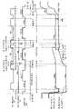
<以1H为单元分割的阈值校正处理的问题><Issues of Threshold Correction Processing in Units of 1H>
图8是帮助说明以1H为单元分割的阈值校正处理的问题的图。如图7所示,在“以1H为单元分割的阈值校正处理”的情况下,其中执行多次阈值校正操作,同时维持驱动晶体管121的漏极电压Vd_121设置在第一电势Vcc、并且电流流动的状态,其中一水平扫描时段作为一处理周期,在各阈值校正处理时段之间的间隔时段内(该间隔时段是从当信号线电势是阈值校正的偏置电势Vofs到改变到下一偏置电势Vofs的时段的信号电势Vin的时段,以下将称为阈值校正操作间隔),采样晶体管125如上所述截止,并且未完全进行驱动晶体管121的阈值校正,使得驱动晶体管121的栅极-源极电压Vgs_121大于阈值电压Vth。FIG. 8 is a diagram to help explain the problem of threshold value correction processing divided into units of 1H. As shown in FIG. 7 , in the case of “threshold correction processing divided in units of 1H”, in which a plurality of threshold correction operations are performed while maintaining the drain voltage Vd_121 of the
在阈值校正操作间隔期间,栅极-源极电压Vgs_121大于阈值电压Vth,电流流过驱动晶体管121,并且在维持该时间点的栅极-源极电压Vgs_121的状态下,源极电势Vs_121和栅极电势Vg_121上升。在此情况下,当阈值校正时间短或阈值校正操作间隔的时间长时,如图8所示,在阈值校正操作间隔期间,驱动晶体管121的源极电势Vs_121极大地上升。结果,在以1H为单元分割的阈值校正处理中,当在下一阈值校正处理时段中再次进行阈值校正时,跨越存储电容器120的电压(即,驱动晶体管121的栅极-源极电压Vgs_121)小于阈值电压Vth_121。此后,没有电流流过驱动晶体管121,并且不正常地执行阈值校正操作(将称为“阈值校正失败现象”),这导致在显示图像中出现的不一致或条纹。例如,当执行高速驱动时,该问题显著地出现,这是因为一水平扫描时段的时间缩短,并且进行阈值校正所花费的时间也减少。During the threshold correction operation interval, the gate-source voltage Vgs_121 is larger than the threshold voltage Vth, the current flows through the
<改进方法:基本原理><Improvement method: basic principle>
有鉴于阈值校正失败现象,在每个阈值校正处理时段中,例如在阈值校正操作间隔期间抑制驱动晶体管121的源极电势Vs_121的上升、并且在阈值校正操作期间使得源极电势Vs_121快速上升是重要的,该阈值校正操作间隔期间作为这样的时段,其中信号线电势是阈值校正的偏置电势Vofs和下一偏置电势Vofs之间的信号电势Vin。两个目标都涉及源极电势Vs_121的上升速度,因此考虑可以从基本类似的角度采取措施。In view of the threshold correction failure phenomenon, it is important to suppress the rise of the source potential Vs_121 of the driving
因为源极电势Vs_121的上升源自流过驱动晶体管121的驱动电流Ids_121,所以在阈值校正操作期间增加驱动电流Ids_121被认为是在阈值校正操作期间使得源极电势Vs_121快速上升的措施方法。因为在以1H为单元分割的阈值校正处理中,在阈值校正操作和阈值校正操作间隔期间的每个时间点处通过栅极电势Vg和源极电势Vs确定栅极-源极电压Vgs_121,所以考虑需要对栅极电势Vg_121和源极电势Vs_121采用所提供的措施以外的方法,以便通过使得驱动晶体管121的驱动电流Ids_121不同于之前的情况来解决上述问题。换句话说,认为下述机制是最佳措施方法,即使当栅极-源极电压Vgs_121相同时,该机制也为驱动电流Ids_121提供差别,使得源极电势Vs_121具有差别。Since the rise of the source potential Vs_121 originates from the drive current Ids_121 flowing through the
因此,作为根据本实施例的措施方法,在以1H为单元分割的阈值校正处理中,在至少一个阈值校正处理时段中,通过在阈值校正操作期间或在阈值校正操作的开始时使得驱动晶体管121的有机EL元件127侧的源极电势Vs_121快速上升,有效地增加阈值校正操作的速度,并且减少在阈值校正操作间隔中源极电势Vs_121的上升的影响,在该阈值校正操作间隔中,阈值校正操作后的信号线电势是信号电势Vin。Therefore, as a countermeasure method according to the present embodiment, in the threshold correction processing divided in units of 1H, in at least one threshold correction processing period, by making the
作为用于使得在阈值校正操作期间在驱动晶体管121的有机EL元件127侧的源极电势Vs_121快速上升的第一措施方法,在至少一个阈值校正处理时段中重复多个分割的次数的阈值校正操作,在该至少一个阈值校正处理时段中,信号线电势(视频信号线106HS的电势)是在反映发光亮度的信号电势Vin和下一信号电势Vin之间的偏置电势Vofs(阈值校正的参考电势)。As a first measure method for causing the source potential Vs_121 of the
即,在以1H为单元分割的阈值校正处理中,其中以一水平扫描时段为一处理周期重复执行多次阈值校正处理,在至少一个阈值校正处理时段期间,同样在一水平扫描时段内的偏置电势Vofs的时段内,分割并重复执行多次阈值校正处理。下述阈值校正处理也称为“应用内部1H阈值校正分割处理的以1H为单元分割的阈值校正处理”或“应用内部1H阈值校正分割处理的分割阈值校正处理”,在所述阈值校正处理中,基于以1H为单元分割的阈值校正处理,在至少一个阈值校正处理时段期间,在一水平扫描时段(1H)内的偏置电势Vofs的时段中,同样执行多次阈值校正处理。That is, in the threshold correction processing divided in units of 1H in which the threshold correction processing is repeatedly executed a plurality of times with one horizontal scanning period as one processing cycle, during at least one threshold correction processing period, also the offset within one horizontal scanning period Within the period of setting the potential Vofs, the threshold value correction process is divided and repeatedly executed a plurality of times. The threshold correction processing described below is also referred to as "threshold correction processing divided in units of 1H to which internal 1H threshold correction division processing is applied" or "segmentation threshold correction processing to which internal 1H threshold correction division processing is applied", in which , based on the threshold correction processing divided in units of 1H, the threshold correction processing is also performed multiple times during at least one threshold correction processing period, in the period of the bias potential Vofs within one horizontal scanning period (1H).
作为用于使得驱动晶体管121的有机EL元件127侧的源极电势Vs_121紧接在阈值校正操作之前快速上升的第二措施方法,在第一阈值校正处理时段期间的阈值校正操作的开始时(紧接在第一阈值校正处理时段期间的阈值校正操作之前),当漏极电流Vd_121改变到第一电势Vcc时采样晶体管125截止,此后在经过一定时段之后采样晶体管125导通,以开始阈值校正操作。第二措施方法是在源极电势Vs_121快速上升后预先执行第一阈值校正操作的机制。顺带提及,尽管第二方法是用于解决在以1H为单元分割的阈值校正处理中、由在阈值校正操作间隔期间源极电势Vs_121的上升引起的问题的机制,但是基本不必联合使用第二方法和以1H为单元分割的阈值校正处理。As a second countermeasure method for causing the source potential Vs_121 of the
在防止出现阈值校正失败现象的短时段内,任何措施方法截止采样晶体管125,从而在维持该时间点的栅极-源极电压Vgs_121的状态下升高栅极电势Vg_121和源极电势Vs_121,此后导通采样晶体管125以将栅极电势Vg_121设置为偏置电势Vofs,并且开始阈值校正操作。这提供了通过源极电势Vs_121在不出现阈值校正失败现象的范围内的上升、增加阈值校正处理时段中的阈值校正操作的速度的作用。因此可能防止在随后的阈值校正操作间隔内由于从电源流到驱动晶体管121的电流,阈值校正操作不正常地出现,并且获得没有条纹或不均匀的一致的图像质量。此外,因为可以增加在阈值校正处理时段期间的阈值校正操作的速度,所以可能将阈值校正处理时段设置得更短,因此实现更高的速度。In a short period of time to prevent the occurrence of the threshold value correction failure phenomenon, any measure method turns off the
顺带提及,当在以1H为单元分割的阈值校正处理期间采用第二措施方法时,可以将第二措施方法与第一措施方法(应用内部1H阈值校正分割处理的以1H为单元分割的阈值校正处理)结合,其在第二阈值校正处理时段和此后期间,在一个水平扫描时段内的偏置电势Vofs的时段中,也执行多次阈值校正处理。以下将具体描述每个措施方法。Incidentally, when the second measure method is employed during the 1H-unit-divided threshold value correction processing, the second measure method can be combined with the first measure method (applying the 1H-unit-divided threshold of the 1H threshold correction division process correction processing) which also executes the threshold value correction processing a plurality of times in the period of the bias potential Vofs within one horizontal scanning period during the second threshold value correction processing period and thereafter. Each measure method will be specifically described below.
<改进方法:第一实施例><Improved Method: First Embodiment>
图9是帮助说明用于消除由于在阈值校正操作间隔内源极电势Vs_121的上升而导致的阈值校正失败现象的方法的第一实施例的图。图9是按原样使用根据图6所示的第三比较示例的像素电路P并且表示线序驱动的情况的时序图。图9在共同时间轴上示出写入扫描线104WS的电势改变、电源线105DSL的电势改变以及视频信号线106HS的电势改变。与这些电势改变并行地,图9还示出对于一行、驱动晶体管121的栅极电势Vg和源极电势Vs的改变。FIG. 9 is a diagram of assistance in explaining a first embodiment of a method for eliminating a threshold correction failure phenomenon due to a rise in the source potential Vs_121 within a threshold correction operation interval. FIG. 9 is a timing chart showing a case where the pixel circuit P according to the third comparative example shown in FIG. 6 is used as it is and shows line-sequential driving. FIG. 9 shows a potential change of the write scan line 104WS, a potential change of the power supply line 105DSL, and a potential change of the video signal line 106HS on a common time axis. In parallel with these potential changes, FIG. 9 also shows changes in the gate potential Vg and the source potential Vs of the
第一实施例采用第一措施方法,其中在以1H为单元分割的阈值校正处理中,在至少一个阈值校正处理时段期间的一个水平扫描时段内的偏置电势Vofs的时段中,也执行多个分割次数的阈值校正处理,在所述以1H为单元分割的阈值校正处理中,以一水平扫描时段为一处理周期重复执行多次阈值校正处理。在以1H为单元分割的阈值校正处理中,当信号线电势是偏置电势Vofs时执行的阈值校正操作的至少一个阈值校正处理时段期间,第一实施例通过重复导通(导通)/截止(不导通)采样晶体管125,重复导通采样晶体管125两次或更多。The first embodiment adopts the first measure method in which, in the threshold correction processing divided in units of 1H, also in the period of the bias potential Vofs within one horizontal scanning period during at least one threshold correction processing period, a plurality of In the threshold correction process divided by the number of divisions, in the threshold correction process divided into units of 1H, the threshold correction process is repeatedly executed multiple times with one horizontal scanning period as a processing cycle. In the threshold correction processing divided in units of 1H, during at least one threshold correction processing period of the threshold correction operation performed when the signal line potential is the offset potential Vofs, the first embodiment repeats ON (ON)/OFF (Non-conducting) the
将内部1H阈值校正分割处理应用到多个阈值校正处理时段中的至少一个就足够了。额外1H阈值校正分割处理可应用到所有阈值校正处理时段,或当额外1H阈值校正分割处理应用到仅仅一个阈值校正处理时段时,基本自由选择额外1H阈值校正分割处理应用到多个阈值校正处理时段中的多少个阈值校正准备时段。然而,关于效果,期望将额外1H阈值校正分割处理应用到至少一个阈值校正处理时段,进一步将偏置电势Vofs的时段分割为多个时段,并且执行阈值校正处理。It is sufficient to apply the internal 1H threshold correction division processing to at least one of the plurality of threshold correction processing periods. The additional 1H threshold correction split processing can be applied to all threshold correction processing periods, or when the additional 1H threshold correction split processing is applied to only one threshold correction processing period, the additional 1H threshold correction split processing is applied to multiple threshold correction processing periods at substantially free choice How many threshold corrections in the preparation period. However, regarding the effect, it is desirable to apply the additional 1H threshold correction division processing to at least one threshold correction processing period, further divide the period of the bias potential Vofs into a plurality of periods, and execute the threshold correction processing.
因此,当在以1H为单元分割的阈值校正处理中的一水平时段内、通过也多次导通/截止采样晶体管125来执行分割阈值校正操作时,在各阈值校正操作期间的间隔时段内采样晶体管125是截止的,因此栅极电势Vg_121和源极电势Vs_121上升,同时在一水平时段内的偏置电势Vofs的时段中,驱动晶体管121的栅极-源极电压Vgs也保持恒定。Therefore, when the divisional threshold correction operation is performed by turning on/off the
在应用内部1H阈值校正分割处理的阈值校正操作时段内的阈值校正操作间隔Ta中,源极电势Vs_121上升,同时从紧接在前的阈值校正操作得到的对应于栅极-源极电压Vgs_121的电流保持。另一方面,当未应用额外1H阈值校正分割处理时,在包括与应用额外1H阈值校正分割处理的阈值校正操作时段内的阈值校正操作间隔相同的时段的总阈值校正操作时段中,在栅极电势Vg_121固定在偏置电势Vofs的情况下,源极电势VS_121上升。因此,随着阈值校正处理进行,减少栅极-源极电压Vgs_121,并且逐渐减少流过驱动晶体管121的电流。因此,随着阈值校正处理进行,源极电势Vs_121的上升也变为缓和。In the threshold correction operation interval Ta within the threshold correction operation period to which the internal 1H threshold correction division process is applied, the source potential Vs_121 rises while the voltage corresponding to the gate-source voltage Vgs_121 obtained from the immediately preceding threshold correction operation current hold. On the other hand, when the additional 1H threshold correction division process is not applied, in the total threshold correction operation period including the same period as the threshold correction operation interval within the threshold correction operation period to which the additional 1H threshold correction division process is applied, at the gate With the potential Vg_121 fixed at the offset potential Vofs, the source potential VS_121 rises. Therefore, as the threshold correction process proceeds, the gate-source voltage Vgs_121 is reduced, and the current flowing through the
因此,通过在采样晶体管125处于截止状态的情况下升高源极电势Vs_121(以及栅极电势Vg_121),在下一阈值校正的开始时的栅极-源极电压Vgs_121(跨越存储电容器120的电势)比未应用根据本实施例的内部1H阈值校正分割处理的情况更接近于阈值电压Vth。因此,阈值校正操作的速度增加。换句话说,在当应用根据本实施例的内部1H阈值校正分割处理时的阈值校正操作间隔内,从以1H为单元的阈值校正的角度而言,栅极-源极电压Vgs_121比当未应用内部1H阈值校正分割处理的情况下在相同时段中进行阈值电压校正时的电压更小。因此,当应用内部1H阈值校正分割处理时在1H单元中阈值校正操作自身的速度比当没有应用内部1H阈值校正分割处理时的速度更快。Therefore, by raising the source potential Vs_121 (and the gate potential Vg_121) with the
此外,在信号线电势是偏置电势Vofs的时段内,采样晶体管125以下述顺序改变到导通状态、截止状态和导通状态。然而,因为在以1H为单元分割的阈值校正处理中,在一个水平时段内的各阈值校正操作之间的间隔时段(信号线电势处于偏置电势Vofs的阈值校正操作间隔,并且该阈值校正操作间隔不横跨信号线电势是信号电势Vin的时段)的截止时间Ta短于在每个水平时段中的各阈值校正操作之间的间隔时段(横跨信号线电势是信号电势Vin的时段的阈值校正操作间隔)的截止时间Tb,所以如由于阈值校正操作间隔内源极电势Vs的上升而导致阈值校正失败现象的出现的问题不出现。Also, during the period in which the signal line potential is the offset potential Vofs, the
因此,根据第一实施例的机制,可以使得当信号线电势是在信号电势Vin_1和下一信号电势Vin_2之间的偏置电势Vofs时的阈值校正操作的速度比根据第三比较示例(即,未应用本实施例的以1H为单元分割的阈值校正处理)的驱动定时中的更快。因为阈值校正操作的速度变得更快,所以紧接在阈值校正处理时段后的栅极-源极电压Vgs_121小于未应用本措施方法的情况(该情况将称为之前的情况)下的栅极-源极电压Vgs_121(即,紧接在阈值校正处理时段后的栅极-源极电压Vgs_121更接近阈值电压Vth)。在阈值校正处理时段后的阈值校正操作间隔内,在栅极-源极电压Vgs_121小于之前情况下的栅极-源极电压Vgs_121的状态下,电流流过驱动晶体管121,并且在维持该时间点的栅极-源极电压Vgs_121的状态下,源极电势Vs_121和栅极电势Vg-121上升。因此,阈值校正操作间隔内的驱动晶体管121的源极电势Vs_121的上升小于前述情况下。Therefore, according to the mechanism of the first embodiment, it is possible to make the speed ratio of the threshold correction operation when the signal line potential is the offset potential Vofs between the signal potential Vin_1 and the next signal potential Vin_2 to be higher than that according to the third comparative example (that is, The threshold value correction processing divided in units of 1H) of the present embodiment is not applied faster in the drive timing. Because the speed of the threshold value correction operation becomes faster, the gate-source voltage Vgs_121 immediately after the threshold value correction processing period is smaller than that in the case where the present countermeasure method is not applied (this case will be referred to as the previous case). - The source voltage Vgs_121 (ie, the gate-source voltage Vgs_121 immediately after the threshold correction processing period is closer to the threshold voltage Vth). During the threshold correction operation interval after the threshold correction processing period, in a state where the gate-source voltage Vgs_121 is smaller than the gate-source voltage Vgs_121 in the previous case, current flows through the
结果,减轻或防止了阈值校正失败现象,该现象由于在各阈值校正处理时段之间的阈值校正操作间隔(即,横跨信号线电势是信号电势Vin的时段的阈值校正操作间隔(各阈值校正处理时段之间的间隔时段))内从电源流到驱动晶体管121的电流导致的源极电势Vs_121的上升而引起。可能正常地执行阈值校正操作,因此获得没有不均匀或条纹的一致的图像质量。此外,因为在应用内部1H阈值校正分割处理的阈值校正处理中可以增加阈值校正操作的速度,所以可以将阈值校正处理时段设置得更短,因此可以增加处理的速度。As a result, the threshold value correction failure phenomenon due to the threshold value correction operation interval between each threshold value correction processing period (that is, the threshold value correction operation interval across the period in which the signal line potential is the signal potential Vin (each threshold value correction operation interval) is alleviated or prevented. caused by a rise in the source potential Vs_121 caused by the current flowing from the power supply to the
顺带提及,在图9中,在以一水平扫描时段为一处理周期重复执行三次阈值校正处理的以1H为单元分割的阈值校正处理中,内部1H阈值校正分割处理应用到前两个阈值校正处理时段,但是内部1H阈值校正分割处理不应用到最后的阈值校正处理时段。然而,内部1H阈值校正分割处理可应用到最后的阈值校正处理时段。Incidentally, in FIG. 9 , in the threshold correction processing divided in units of 1H in which the threshold correction processing is repeatedly executed three times with one horizontal scanning period as one processing cycle, the internal 1H threshold correction division processing is applied to the first two threshold correction processes. processing period, but the internal 1H threshold correction split processing is not applied to the last threshold correction processing period. However, the internal 1H threshold correction division processing can be applied to the last threshold correction processing period.
<改进方法:第二实施例><Improved Method: Second Embodiment>
图10是帮助说明用于消除由于在阈值校正操作间隔中源极电势Vs_121的上升而导致阈值校正失败的现象的方法的第二实施例的图。图10还是其中按原样使用根据图6所示的第三比较示例的像素电路P、并且表示线序驱动的情况的时序图。图10在共同时间轴上示出写入扫描线104WS的电势的改变、电源线105DSL的电势的改变、以及视频信号线106HS的电势的改变。与这些电势改变并行地,图10还示出对于一行、驱动晶体管121的栅极电势Vg和源极电势Vs的改变。FIG. 10 is a diagram of assistance in explaining a second embodiment of a method for eliminating a phenomenon that threshold value correction fails due to a rise in the source potential Vs_121 in a threshold value correction operation interval. FIG. 10 is also a timing chart showing a case where the pixel circuit P according to the third comparative example shown in FIG. 6 is used as it is, and shows line-sequential driving. FIG. 10 shows a change in the potential of the write scan line 104WS, a change in the potential of the power supply line 105DSL, and a change in the potential of the video signal line 106HS on a common time axis. In parallel with these potential changes, FIG. 10 also shows changes in the gate potential Vg and the source potential Vs of the
第二实施例采用第二措施方法,其中在以1H为单元分割的阈值校正处理中,在第一阈值校正处理时段期间的阈值校正操作的开始时,当漏极电流Vd_121改变到第一电势Vcc时,采样晶体管125截止,此后在经过一定时段后,采样晶体管125导通,以开始阈值校正操作,在所述以1H为单元分割的阈值校正处理中,以一水平扫描时段为一处理周期重复执行多次阈值校正处理。The second embodiment employs a second measure method in which, in the threshold correction processing divided in units of 1H, at the start of the threshold correction operation during the first threshold correction processing period, when the drain current Vd_121 changes to the first potential Vcc , the
即,在阈值校正处理的准备处理后,并且在第一阈值校正处理的开始之前,当信号线电势是偏置电势Vofs并采样晶体管125截止时,电源驱动脉冲DSL从第二电势Vss上升到第一电势Vcc,电流经过驱动晶体管121,并且栅极电势Vg_121和源极电势Vs_121上升,同时维持栅极-源极电压Vgs_121。在经过一定时间(Tc)之后,写入驱动脉冲WS设置为有效H,采样晶体管125导通,并且栅极电势Vg_121设置为偏置电势Vofs,以开始阈值校正操作。简而言之,第二实施例的特征在于,在第一阈值校正处理的开始之前,通过升高源极电势Vs_121(即,执行源极电势Vs_121的预备升高处理)、同时采样晶体管125保持截止,使得在第一阈值校正处理的开始时的源极电势Vs_121更接近栅极电势Vg_121(=偏置电势Vofs)。That is, after the preparatory process of the threshold correction process and before the start of the first threshold correction process, when the signal line potential is the offset potential Vofs and the
因此,在阈值校正操作之前的栅极电势Vg_121和源极电势Vs_121的初始化之后,并且在第一阈值校正操作之前,当在采样晶体管125设置在截止状态的情况下、电源驱动脉冲DSL从第二电势Vss改变到第一电势Vcc时,此后采样晶体管125导通,以提供偏置电势Vofs到驱动晶体管121的栅极并开始阈值校正操作,源极电势Vs_121可在阈值校正操作的开始之前的短时段Tc内提前升高,在该短时段Tc内,防止出现阈值校正失败现象。Therefore, after the initialization of the gate potential Vg_121 and the source potential Vs_121 before the threshold correction operation, and before the first threshold correction operation, when the
采样晶体管125按下述顺序导通、截止和导通,并且在信号线电势是偏置电势Vofs的第一阈值校正处理时段期间,在阈值校正操作之前,电源驱动脉冲DSL从第二电势Vss改变到第一电势Vcc。然而,因为在以1H为单元分割的阈值校正处理中的每个水平时段中,在从电源驱动脉冲DSL改变到第一电势Vcc到导通采样晶体管125的时间Tc(其间栅极电势Vg_121和源极电势Vs_121上升)短于各阈值校正操作之间的间隔时段(横跨信号线电势是信号电势Vin的时段的阈值校正操作间隔)内栅极电势Vg_121和源极电势Vs_121上升的时间Tb,所以如由于源极电势Vs_121的上升而导致的阈值校正失败的现象的出现的问题不出现。The
换句话说,重要的是,当使第一阈值校正处理的开始时的源极电势Vs_121更接近栅极电势Vg_121(=偏置电势Vofs)时,不仅“时间Tc短于时间,Tb”而且时间Tc设置在驱动晶体管121的有机EL元件127侧的源极电势Vs_121不上升到“Vofs-Vth”的范围内,使得防止在第一阈值校正处理的开始时、驱动晶体管121的栅极-源极电压Vgs_121(跨越存储电容器120的电压)变得小于阈值电压Vth。In other words, it is important that not only "the time Tc is shorter than the time, Tb" but also the time Tc is set so that the source potential Vs_121 of the
结果,可以增加在第一阈值校正处理时段中的阈值校正操作的速度,并且可以使得在第一和第二阈值校正处理时段之间的间隔时段内的驱动晶体管121的源极电势Vs_121的上升量小于在没有应用本实施例的情况下的上升量。因此,如在第一实施例中,在横跨信号线电势是信号电势Vin的时段的阈值校正操作间隔中,可能防止由于从电源流到驱动晶体管121的电流而导致阈值校正操作不正常地执行。可以正常地执行阈值校正操作,因此可以获得没有不均匀或条纹的一致的图像质量。此外,因为如第一实施例中,可以通过预先快速升高源极电势Vs_121来在第一阈值校正处理中增加阈值校正操作的速度,所以可以将阈值校正处理时段设置得更短,因此可以增加处理的速度。As a result, the speed of the threshold correction operation in the first threshold correction processing period can be increased, and the amount of rise in the source potential Vs_121 of the
顺带提及,在图10中,将以1H为单元分割的阈值校正处理与根据第一实施例的方法结合,在以1H为单元分割的阈值校正处理中,以一水平扫描时段为一处理周期重复执行三次阈值校正处理,在第二阈值校正处理时段中,对根据第一实施例的方法应用内部1H阈值校正分割处理。然而,与第一实施例的结合不是必须的。当然,如在第一实施例中,内部1H阈值校正分割处理还可应用到最后的阈值校正处理时段。Incidentally, in FIG. 10 , threshold correction processing divided in units of 1H is combined with the method according to the first embodiment, and in the threshold correction processing divided in units of 1H, one horizontal scanning period is used as one processing cycle The threshold correction processing is repeatedly performed three times, and in the second threshold correction processing period, the internal 1H threshold correction division processing is applied to the method according to the first embodiment. However, the combination with the first embodiment is not essential. Of course, as in the first embodiment, the internal 1H threshold correction division processing can also be applied to the last threshold correction processing period.
尽管已经使用本发明的实施例在上面描述了本发明,但是本发明的技术范围不限于在上述实施例中描述的范围。可对上述实施例进行各种改变和改进,而不背离本发明的精神,并且通过添加这些改变和改进获得的形式也包括在本发明的技术范围内。Although the present invention has been described above using the embodiments of the present invention, the technical scope of the present invention is not limited to the scope described in the above-described embodiments. Various changes and improvements can be made to the above-described embodiments without departing from the spirit of the present invention, and forms obtained by adding these changes and improvements are also included in the technical scope of the present invention.
此外,前述实施例不限制所要求保护的本发明,并且实施例中描述的特征的所有组合不一定都是本发明的解决手段所必要的。前述实施例包括各种阶段的发明,并且通过适当组合多个所公开的构成要求可提取各种发明。即使从实施例中公开的所有构成要求中省略一些构成要求,从一些构成要求的省略得到的构成也可提取为本发明,只要获得效果。Furthermore, the foregoing embodiments do not limit the claimed invention, and not all combinations of features described in the embodiments are necessarily essential to the solution means of the present invention. The aforementioned embodiments include inventions at various stages, and various inventions can be extracted by appropriately combining a plurality of disclosed constitutional requirements. Even if some constitutional requirements are omitted from all the constitutional requirements disclosed in the embodiments, the configuration resulting from the omission of some constitutional requirements can be extracted as the present invention as long as effects are obtained.
<像素电路的修改示例><Modification example of pixel circuit>
例如,可对像素电路P的模式进行改变。例如,“对偶性原理”在电路理论中成立,因此可从该角度对像素电路P进行修改。在此情况下,虽然附图中没有示出,虽然前述每个实施例中示出的像素电路P使用n沟道型驱动晶体管121形成,但是像素电路P使用p沟道型驱动晶体管121形成。相应地进行服从对偶性原理的改变,如例如关于视频信号Vsig的偏置电势Vofs和电源电压的大小关系颠倒信号幅度ΔVin的极性。For example, the mode of the pixel circuit P may be changed. For example, the "principle of duality" is established in circuit theory, so the pixel circuit P can be modified from this point of view. In this case, although not shown in the drawings, although the pixel circuit P shown in each of the foregoing embodiments is formed using the n-channel
例如,在服从“对偶性原理”的修改模式下的像素电路P中,存储电容器120连接在p型驱动晶体管(以下称为p型驱动晶体管121p)的栅极端和源极端之间,并且p型驱动晶体管121p的源极端直接连接到有机EL元件127的阴极端。有机EL元件127的阳极端设置在作为参考电势的阳极电势Vanode。阳极电势Vanode连接到参考电源(高电势侧),其提供参考电势并对所有像素是共同的。p型驱动晶体管121p使其漏极端连接到低电压侧的第一电势Vss。p型驱动晶体管121p馈送用于使得有机EL元件127发光的驱动电流Ids。For example, in the pixel circuit P in the modification mode obeying the "duality principle", the
如使用n性驱动晶体管121的有机EL显示设备,根据修改的示例的有机EL显示设备可执行阈值校正操作、迁移率校正操作和自举操作,在所述修改的示例中,通过应用这样的对偶性原理将驱动晶体管121改变为p型。Like the organic EL display device using the n-
当驱动这样的像素电路P时,可采用类似于第一实施例的模式,其中在至少一个阈值校正处理时段期间的一个水平扫描时段内的偏置电势Vofs的时段中,也分割并重复执行多次阈值校正处理。此外,可采用类似于第二实施例的模式,其中在第一阈值校正处理时段中的阈值校正操作的开始时,当漏极电流Vd_121改变为第一电势Vcc时,采样晶体管125截止,此后,在经过一定时段后,采样晶体管125导通,以开始阈值校正操作。当然,可采用将这些模式彼此组合的模式。可能减少在阈值校正操作间隔流过p型驱动晶体管121p的驱动电流Ids_121p,因此正常地执行阈值校正操作。因此,因为可以正常地执行阈值校正操作,所以可以获得没有不均匀或条纹的一致的图像质量。When such a pixel circuit P is driven, a mode similar to that of the first embodiment can be employed in which also in the period of the bias potential Vofs within one horizontal scanning period during at least one threshold value correction processing period, multiple Subthreshold correction processing. Furthermore, a mode similar to the second embodiment may be employed in which at the start of the threshold correction operation in the first threshold correction processing period, when the drain current Vd_121 changes to the first potential Vcc, the
要注意,尽管通过对前面第一到第二实施例所示的配置进行服从“对偶性原理”的修改,获得如上所述的像素电路P的修改的示例,但是改变电路的方法不限于此。形成像素电路P的晶体管的数量是任意的,只要在执行阈值校正操作时,执行驱动,使得根据写入扫描部分104的扫描在每个水平时段内在偏置电势Vofs和信号电势Vin(=Vofs+ΔVin)之间改变的视频信号Vsig发送到视频信号线106HS,并且在第一电势和第二电势之间切换驱动驱动晶体管121的漏极侧(电源侧),用于初始化阈值校正的操作。像素电路P是否是2TR配置没有关系,并且晶体管的数量可以是三个或更多。通过采用上述本实施例的改进方法来补救在阈值校正操作间隔内由于源极电势Vs_121的上升而导致的阈值校正失败现象的本实施例的概念可应用到所有配置。It is to be noted that although an example of modification of the pixel circuit P as described above is obtained by modifying the configurations shown in the foregoing first to second embodiments to obey the "principle of duality", the method of changing the circuit is not limited thereto. The number of transistors forming the pixel circuit P is arbitrary as long as when the threshold correction operation is performed, driving is performed so that the bias potential Vofs and the signal potential Vin(=Vofs+ The video signal Vsig changed between ΔVin) is sent to the video signal line 106HS, and the drain side (power supply side) of the
此外,在执行阈值校正操作中将偏置电势Vofs和信号电势Vin提供到驱动晶体管121的栅极的机制不限于如前述实施例的2TR配置中通过视频信号Vsig来提供。例如,可采用如专利文献1中所描述的、经由另一晶体管提供偏置电势Vofs和信号电势Vin的机制,作为提供偏置电势Vofs和信号电势Vin到驱动晶体管121的栅极的机制。同样在这些修改示例中,可以采用通过应用上述本实施例的改进方法、补救在阈值校正操作间隔内由于源极电势Vs_121的上升而导致的阈值校正失败现象的本实施例的概念。Furthermore, the mechanism of supplying the bias potential Vofs and the signal potential Vin to the gate of the
此外,前述实施例的概念可在理论上应用到专利文献1中描述的机制。然而,因为专利文献1中描述的阈值校正处理可花费充足的时间来进行一次阈值校正,所以可以认为,与2TR配置和基于2TR配置的各种修改示例相比,不太需要前述实施例。Furthermore, the concepts of the aforementioned embodiments can be theoretically applied to the mechanism described in
本申请包含涉及于2008年6月25日向日本专利局提交的日本优先权专利申请JP 2008-165201中公开的主题,在此通过引用并入其全部内容。The present application contains subject matter related to that disclosed in Japanese Priority Patent Application JP 2008-165201 filed in the Japan Patent Office on Jun. 25, 2008, the entire content of which is hereby incorporated by reference.
本领域技术人员应当理解,依赖于设计需求和其他因素可以出现各种修改、组合、子组合和更改,只要它们在权利要求或其等效物的范围内。It should be understood by those skilled in the art that various modifications, combinations, sub-combinations and alterations may occur depending on design requirements and other factors insofar as they are within the scope of the claims or the equivalents thereof.
Claims (9)
Applications Claiming Priority (2)
| Application Number | Priority Date | Filing Date | Title |
|---|---|---|---|
| JP165201/08 | 2008-06-25 | ||
| JP2008165201AJP2010008521A (en) | 2008-06-25 | 2008-06-25 | Display device |
Publications (2)
| Publication Number | Publication Date |
|---|---|
| CN101615376Atrue CN101615376A (en) | 2009-12-30 |
| CN101615376B CN101615376B (en) | 2012-08-08 |
Family
ID=41446804
Family Applications (1)
| Application Number | Title | Priority Date | Filing Date |
|---|---|---|---|
| CN2009101508725AActiveCN101615376B (en) | 2008-06-25 | 2009-06-25 | Display device |
Country Status (4)
| Country | Link |
|---|---|
| US (1) | US8581807B2 (en) |
| JP (1) | JP2010008521A (en) |
| CN (1) | CN101615376B (en) |
| TW (1) | TWI424410B (en) |
Cited By (27)
| Publication number | Priority date | Publication date | Assignee | Title |
|---|---|---|---|---|
| CN104576485A (en)* | 2013-10-17 | 2015-04-29 | 株式会社信科模具 | Method for preparing an electrode pattern of conductive silicone rubber, electrostatic chuck composed entirely of silicone rubber, and method for manufacturing the same |
| CN105144361A (en)* | 2013-04-22 | 2015-12-09 | 伊格尼斯创新公司 | Inspection system for OLED display panels |
| US9842544B2 (en) | 2006-04-19 | 2017-12-12 | Ignis Innovation Inc. | Stable driving scheme for active matrix displays |
| US9997107B2 (en) | 2013-03-15 | 2018-06-12 | Ignis Innovation Inc. | AMOLED displays with multiple readout circuits |
| US10032399B2 (en) | 2010-02-04 | 2018-07-24 | Ignis Innovation Inc. | System and methods for extracting correlation curves for an organic light emitting device |
| US10043448B2 (en) | 2012-02-03 | 2018-08-07 | Ignis Innovation Inc. | Driving system for active-matrix displays |
| US10127846B2 (en) | 2011-05-20 | 2018-11-13 | Ignis Innovation Inc. | System and methods for extraction of threshold and mobility parameters in AMOLED displays |
| US10176738B2 (en) | 2012-05-23 | 2019-01-08 | Ignis Innovation Inc. | Display systems with compensation for line propagation delay |
| US10181282B2 (en) | 2015-01-23 | 2019-01-15 | Ignis Innovation Inc. | Compensation for color variations in emissive devices |
| US10186190B2 (en) | 2013-12-06 | 2019-01-22 | Ignis Innovation Inc. | Correction for localized phenomena in an image array |
| US10198979B2 (en) | 2013-03-14 | 2019-02-05 | Ignis Innovation Inc. | Re-interpolation with edge detection for extracting an aging pattern for AMOLED displays |
| US10304390B2 (en) | 2009-11-30 | 2019-05-28 | Ignis Innovation Inc. | System and methods for aging compensation in AMOLED displays |
| US10311780B2 (en) | 2015-05-04 | 2019-06-04 | Ignis Innovation Inc. | Systems and methods of optical feedback |
| US10319307B2 (en) | 2009-06-16 | 2019-06-11 | Ignis Innovation Inc. | Display system with compensation techniques and/or shared level resources |
| US10325537B2 (en) | 2011-05-20 | 2019-06-18 | Ignis Innovation Inc. | System and methods for extraction of threshold and mobility parameters in AMOLED displays |
| US10339860B2 (en) | 2015-08-07 | 2019-07-02 | Ignis Innovation, Inc. | Systems and methods of pixel calibration based on improved reference values |
| US10380944B2 (en) | 2011-11-29 | 2019-08-13 | Ignis Innovation Inc. | Structural and low-frequency non-uniformity compensation |
| US10388221B2 (en) | 2005-06-08 | 2019-08-20 | Ignis Innovation Inc. | Method and system for driving a light emitting device display |
| US10403230B2 (en) | 2015-05-27 | 2019-09-03 | Ignis Innovation Inc. | Systems and methods of reduced memory bandwidth compensation |
| US10417945B2 (en) | 2011-05-27 | 2019-09-17 | Ignis Innovation Inc. | Systems and methods for aging compensation in AMOLED displays |
| US10439159B2 (en) | 2013-12-25 | 2019-10-08 | Ignis Innovation Inc. | Electrode contacts |
| US10573231B2 (en) | 2010-02-04 | 2020-02-25 | Ignis Innovation Inc. | System and methods for extracting correlation curves for an organic light emitting device |
| US10699613B2 (en) | 2009-11-30 | 2020-06-30 | Ignis Innovation Inc. | Resetting cycle for aging compensation in AMOLED displays |
| US10699624B2 (en) | 2004-12-15 | 2020-06-30 | Ignis Innovation Inc. | Method and system for programming, calibrating and/or compensating, and driving an LED display |
| US10706754B2 (en) | 2011-05-26 | 2020-07-07 | Ignis Innovation Inc. | Adaptive feedback system for compensating for aging pixel areas with enhanced estimation speed |
| US10971043B2 (en) | 2010-02-04 | 2021-04-06 | Ignis Innovation Inc. | System and method for extracting correlation curves for an organic light emitting device |
| US11200839B2 (en) | 2010-02-04 | 2021-12-14 | Ignis Innovation Inc. | System and methods for extracting correlation curves for an organic light emitting device |
Families Citing this family (5)
| Publication number | Priority date | Publication date | Assignee | Title |
|---|---|---|---|---|
| KR101784014B1 (en)* | 2010-11-10 | 2017-10-10 | 가부시키가이샤 제이올레드 | Organic el display panel and method for driving the same |
| KR102234021B1 (en)* | 2014-09-19 | 2021-03-31 | 엘지디스플레이 주식회사 | Organic light emitting display |
| US10580352B2 (en)* | 2018-07-03 | 2020-03-03 | Facebook Technologies, Llc | Testing of micro light emitting diodes (LEDs) using probe pads |
| CN112334782A (en)* | 2018-07-03 | 2021-02-05 | 脸谱科技有限责任公司 | Testing Tiny Light Emitting Diodes (LEDs) with Probe Pads |
| KR102825489B1 (en)* | 2021-09-28 | 2025-06-27 | 삼성디스플레이 주식회사 | Display apparatus |
Family Cites Families (11)
| Publication number | Priority date | Publication date | Assignee | Title |
|---|---|---|---|---|
| JPH09292858A (en)* | 1996-04-24 | 1997-11-11 | Futaba Corp | Display device |
| JP2001051643A (en)* | 1999-06-02 | 2001-02-23 | Sony Corp | Display device and driving method |
| JP5210478B2 (en)* | 2001-08-31 | 2013-06-12 | 株式会社半導体エネルギー研究所 | Display device |
| JP4423848B2 (en)* | 2002-10-31 | 2010-03-03 | ソニー株式会社 | Image display device and color balance adjustment method thereof |
| JP2004191752A (en)* | 2002-12-12 | 2004-07-08 | Seiko Epson Corp | Electro-optical device, electro-optical device driving method, and electronic apparatus |
| JP4945063B2 (en)* | 2004-03-15 | 2012-06-06 | 東芝モバイルディスプレイ株式会社 | Active matrix display device |
| JP4923410B2 (en) | 2005-02-02 | 2012-04-25 | ソニー株式会社 | Pixel circuit and display device |
| JP4923505B2 (en)* | 2005-10-07 | 2012-04-25 | ソニー株式会社 | Pixel circuit and display device |
| JP5245195B2 (en)* | 2005-11-14 | 2013-07-24 | ソニー株式会社 | Pixel circuit |
| JP4203772B2 (en)* | 2006-08-01 | 2009-01-07 | ソニー株式会社 | Display device and driving method thereof |
| JP4826597B2 (en)* | 2008-03-31 | 2011-11-30 | ソニー株式会社 | Display device |
- 2008
- 2008-06-25JPJP2008165201Apatent/JP2010008521A/enactivePending
- 2009
- 2009-06-02TWTW098118232Apatent/TWI424410B/enactive
- 2009-06-08USUS12/457,316patent/US8581807B2/enactiveActive
- 2009-06-25CNCN2009101508725Apatent/CN101615376B/enactiveActive
Cited By (35)
| Publication number | Priority date | Publication date | Assignee | Title |
|---|---|---|---|---|
| US10699624B2 (en) | 2004-12-15 | 2020-06-30 | Ignis Innovation Inc. | Method and system for programming, calibrating and/or compensating, and driving an LED display |
| US10388221B2 (en) | 2005-06-08 | 2019-08-20 | Ignis Innovation Inc. | Method and system for driving a light emitting device display |
| US10453397B2 (en) | 2006-04-19 | 2019-10-22 | Ignis Innovation Inc. | Stable driving scheme for active matrix displays |
| US10127860B2 (en) | 2006-04-19 | 2018-11-13 | Ignis Innovation Inc. | Stable driving scheme for active matrix displays |
| US9842544B2 (en) | 2006-04-19 | 2017-12-12 | Ignis Innovation Inc. | Stable driving scheme for active matrix displays |
| US10319307B2 (en) | 2009-06-16 | 2019-06-11 | Ignis Innovation Inc. | Display system with compensation techniques and/or shared level resources |
| US10699613B2 (en) | 2009-11-30 | 2020-06-30 | Ignis Innovation Inc. | Resetting cycle for aging compensation in AMOLED displays |
| US10304390B2 (en) | 2009-11-30 | 2019-05-28 | Ignis Innovation Inc. | System and methods for aging compensation in AMOLED displays |
| US11200839B2 (en) | 2010-02-04 | 2021-12-14 | Ignis Innovation Inc. | System and methods for extracting correlation curves for an organic light emitting device |
| US10032399B2 (en) | 2010-02-04 | 2018-07-24 | Ignis Innovation Inc. | System and methods for extracting correlation curves for an organic light emitting device |
| US10573231B2 (en) | 2010-02-04 | 2020-02-25 | Ignis Innovation Inc. | System and methods for extracting correlation curves for an organic light emitting device |
| US10971043B2 (en) | 2010-02-04 | 2021-04-06 | Ignis Innovation Inc. | System and method for extracting correlation curves for an organic light emitting device |
| US10395574B2 (en) | 2010-02-04 | 2019-08-27 | Ignis Innovation Inc. | System and methods for extracting correlation curves for an organic light emitting device |
| US10580337B2 (en) | 2011-05-20 | 2020-03-03 | Ignis Innovation Inc. | System and methods for extraction of threshold and mobility parameters in AMOLED displays |
| US10127846B2 (en) | 2011-05-20 | 2018-11-13 | Ignis Innovation Inc. | System and methods for extraction of threshold and mobility parameters in AMOLED displays |
| US10325537B2 (en) | 2011-05-20 | 2019-06-18 | Ignis Innovation Inc. | System and methods for extraction of threshold and mobility parameters in AMOLED displays |
| US10706754B2 (en) | 2011-05-26 | 2020-07-07 | Ignis Innovation Inc. | Adaptive feedback system for compensating for aging pixel areas with enhanced estimation speed |
| US10417945B2 (en) | 2011-05-27 | 2019-09-17 | Ignis Innovation Inc. | Systems and methods for aging compensation in AMOLED displays |
| US10380944B2 (en) | 2011-11-29 | 2019-08-13 | Ignis Innovation Inc. | Structural and low-frequency non-uniformity compensation |
| US10453394B2 (en) | 2012-02-03 | 2019-10-22 | Ignis Innovation Inc. | Driving system for active-matrix displays |
| US10043448B2 (en) | 2012-02-03 | 2018-08-07 | Ignis Innovation Inc. | Driving system for active-matrix displays |
| US10176738B2 (en) | 2012-05-23 | 2019-01-08 | Ignis Innovation Inc. | Display systems with compensation for line propagation delay |
| US10198979B2 (en) | 2013-03-14 | 2019-02-05 | Ignis Innovation Inc. | Re-interpolation with edge detection for extracting an aging pattern for AMOLED displays |
| US10460660B2 (en) | 2013-03-15 | 2019-10-29 | Ingis Innovation Inc. | AMOLED displays with multiple readout circuits |
| US9997107B2 (en) | 2013-03-15 | 2018-06-12 | Ignis Innovation Inc. | AMOLED displays with multiple readout circuits |
| US10867536B2 (en) | 2013-04-22 | 2020-12-15 | Ignis Innovation Inc. | Inspection system for OLED display panels |
| CN105144361A (en)* | 2013-04-22 | 2015-12-09 | 伊格尼斯创新公司 | Inspection system for OLED display panels |
| CN104576485A (en)* | 2013-10-17 | 2015-04-29 | 株式会社信科模具 | Method for preparing an electrode pattern of conductive silicone rubber, electrostatic chuck composed entirely of silicone rubber, and method for manufacturing the same |
| CN104576485B (en)* | 2013-10-17 | 2018-12-07 | 株式会社信科模具 | The production method and all-silicon rubber electrostatic chuck and its manufacturing method of conductivity silicon rubber electrode pattern |
| US10186190B2 (en) | 2013-12-06 | 2019-01-22 | Ignis Innovation Inc. | Correction for localized phenomena in an image array |
| US10439159B2 (en) | 2013-12-25 | 2019-10-08 | Ignis Innovation Inc. | Electrode contacts |
| US10181282B2 (en) | 2015-01-23 | 2019-01-15 | Ignis Innovation Inc. | Compensation for color variations in emissive devices |
| US10311780B2 (en) | 2015-05-04 | 2019-06-04 | Ignis Innovation Inc. | Systems and methods of optical feedback |
| US10403230B2 (en) | 2015-05-27 | 2019-09-03 | Ignis Innovation Inc. | Systems and methods of reduced memory bandwidth compensation |
| US10339860B2 (en) | 2015-08-07 | 2019-07-02 | Ignis Innovation, Inc. | Systems and methods of pixel calibration based on improved reference values |
Also Published As
| Publication number | Publication date |
|---|---|
| US20090322734A1 (en) | 2009-12-31 |
| US8581807B2 (en) | 2013-11-12 |
| JP2010008521A (en) | 2010-01-14 |
| TW201003606A (en) | 2010-01-16 |
| CN101615376B (en) | 2012-08-08 |
| TWI424410B (en) | 2014-01-21 |
Similar Documents
| Publication | Publication Date | Title |
|---|---|---|
| US8581807B2 (en) | Display device and pixel circuit driving method achieving driving transistor threshold voltage correction | |
| US8830149B2 (en) | Display device | |
| US7898509B2 (en) | Pixel circuit, display, and method for driving pixel circuit | |
| JP4915195B2 (en) | Display device | |
| TWI434261B (en) | A display device, and a display device | |
| JP5217500B2 (en) | EL display panel module, EL display panel, integrated circuit device, electronic apparatus, and drive control method | |
| CN102867840B (en) | The driving method of image element circuit, display, electronic installation and image element circuit | |
| JP4826597B2 (en) | Display device | |
| JP5157467B2 (en) | Self-luminous display device and driving method thereof | |
| JP4293262B2 (en) | Display device, display device driving method, and electronic apparatus | |
| US20080225027A1 (en) | Pixel circuit, display device, and driving method thereof | |
| US20100289832A1 (en) | Display apparatus | |
| US8552937B2 (en) | Pixel circuit and display device | |
| US20080278464A1 (en) | Pixel circuit and display device | |
| JP2010266493A (en) | Driving method for pixel circuit and display apparatus | |
| JP2021067901A (en) | Pixel circuit and display device | |
| JP2009229635A (en) | Display and its manufacturing method | |
| JP2008310127A (en) | Display device, driving method of display device and electronic equipment | |
| JP2008145647A (en) | Display device and method of driving the same | |
| JP5789585B2 (en) | Display device and electronic device | |
| JP2008233125A (en) | Display device, driving method of display device, and electronic equipment | |
| JP2008185874A (en) | Pixel circuit, display device and driving method therefor | |
| JP2008286897A (en) | Display device, method for driving the display device, and electronic equipment | |
| JP4915194B2 (en) | Display device | |
| JP2008203706A (en) | Display device and driving method of display device, and electronic equipment |
Legal Events
| Date | Code | Title | Description |
|---|---|---|---|
| C06 | Publication | ||
| PB01 | Publication | ||
| C10 | Entry into substantive examination | ||
| SE01 | Entry into force of request for substantive examination | ||
| C14 | Grant of patent or utility model | ||
| GR01 | Patent grant | ||
| ASS | Succession or assignment of patent right | Owner name:JANPAN ORGANIC RATE DISPLAY CO., LTD. Free format text:FORMER OWNER: SONY CORPORATION Effective date:20150805 | |
| C41 | Transfer of patent application or patent right or utility model | ||
| TR01 | Transfer of patent right | Effective date of registration:20150805 Address after:Tokyo, Japan Patentee after:JOLED Inc. Address before:Tokyo, Japan Patentee before:Sony Corp. | |
| TR01 | Transfer of patent right | Effective date of registration:20231205 Address after:Tokyo, Japan Patentee after:Japan Display Design and Development Contract Society Address before:Tokyo, Japan Patentee before:JOLED Inc. | |
| TR01 | Transfer of patent right | ||
| TR01 | Transfer of patent right | Effective date of registration:20250724 Address after:Tokyo, Japan Patentee after:Magno Bolan Co.,Ltd. Country or region after:Japan Address before:Tokyo, Japan Patentee before:Japan Display Design and Development Contract Society Country or region before:Japan | |
| TR01 | Transfer of patent right |