CN101614367B - Light-emitting diode lamp - Google Patents
Light-emitting diode lampDownload PDFInfo
- Publication number
- CN101614367B CN101614367BCN2008100681110ACN200810068111ACN101614367BCN 101614367 BCN101614367 BCN 101614367BCN 2008100681110 ACN2008100681110 ACN 2008100681110ACN 200810068111 ACN200810068111 ACN 200810068111ACN 101614367 BCN101614367 BCN 101614367B
- Authority
- CN
- China
- Prior art keywords
- light
- emitting diode
- module
- lamp
- substrate
- Prior art date
- Legal status (The legal status is an assumption and is not a legal conclusion. Google has not performed a legal analysis and makes no representation as to the accuracy of the status listed.)
- Expired - Fee Related
Links
Images

Classifications
- F—MECHANICAL ENGINEERING; LIGHTING; HEATING; WEAPONS; BLASTING
- F21—LIGHTING
- F21V—FUNCTIONAL FEATURES OR DETAILS OF LIGHTING DEVICES OR SYSTEMS THEREOF; STRUCTURAL COMBINATIONS OF LIGHTING DEVICES WITH OTHER ARTICLES, NOT OTHERWISE PROVIDED FOR
- F21V19/00—Fastening of light sources or lamp holders
- F21V19/001—Fastening of light sources or lamp holders the light sources being semiconductors devices, e.g. LEDs
- F21V19/003—Fastening of light source holders, e.g. of circuit boards or substrates holding light sources
- F21V19/0055—Fastening of light source holders, e.g. of circuit boards or substrates holding light sources by screwing
- F—MECHANICAL ENGINEERING; LIGHTING; HEATING; WEAPONS; BLASTING
- F21—LIGHTING
- F21K—NON-ELECTRIC LIGHT SOURCES USING LUMINESCENCE; LIGHT SOURCES USING ELECTROCHEMILUMINESCENCE; LIGHT SOURCES USING CHARGES OF COMBUSTIBLE MATERIAL; LIGHT SOURCES USING SEMICONDUCTOR DEVICES AS LIGHT-GENERATING ELEMENTS; LIGHT SOURCES NOT OTHERWISE PROVIDED FOR
- F21K9/00—Light sources using semiconductor devices as light-generating elements, e.g. using light-emitting diodes [LED] or lasers
- F21K9/60—Optical arrangements integrated in the light source, e.g. for improving the colour rendering index or the light extraction
- F—MECHANICAL ENGINEERING; LIGHTING; HEATING; WEAPONS; BLASTING
- F21—LIGHTING
- F21V—FUNCTIONAL FEATURES OR DETAILS OF LIGHTING DEVICES OR SYSTEMS THEREOF; STRUCTURAL COMBINATIONS OF LIGHTING DEVICES WITH OTHER ARTICLES, NOT OTHERWISE PROVIDED FOR
- F21V11/00—Screens not covered by groups F21V1/00, F21V3/00, F21V7/00 or F21V9/00
- F21V11/02—Screens not covered by groups F21V1/00, F21V3/00, F21V7/00 or F21V9/00 using parallel laminae or strips, e.g. of Venetian-blind type
- F—MECHANICAL ENGINEERING; LIGHTING; HEATING; WEAPONS; BLASTING
- F21—LIGHTING
- F21V—FUNCTIONAL FEATURES OR DETAILS OF LIGHTING DEVICES OR SYSTEMS THEREOF; STRUCTURAL COMBINATIONS OF LIGHTING DEVICES WITH OTHER ARTICLES, NOT OTHERWISE PROVIDED FOR
- F21V13/00—Producing particular characteristics or distribution of the light emitted by means of a combination of elements specified in two or more of main groups F21V1/00 - F21V11/00
- F21V13/02—Combinations of only two kinds of elements
- F21V13/10—Combinations of only two kinds of elements the elements being reflectors and screens
- F—MECHANICAL ENGINEERING; LIGHTING; HEATING; WEAPONS; BLASTING
- F21—LIGHTING
- F21V—FUNCTIONAL FEATURES OR DETAILS OF LIGHTING DEVICES OR SYSTEMS THEREOF; STRUCTURAL COMBINATIONS OF LIGHTING DEVICES WITH OTHER ARTICLES, NOT OTHERWISE PROVIDED FOR
- F21V17/00—Fastening of component parts of lighting devices, e.g. shades, globes, refractors, reflectors, filters, screens, grids or protective cages
- F21V17/10—Fastening of component parts of lighting devices, e.g. shades, globes, refractors, reflectors, filters, screens, grids or protective cages characterised by specific fastening means or way of fastening
- F21V17/12—Fastening of component parts of lighting devices, e.g. shades, globes, refractors, reflectors, filters, screens, grids or protective cages characterised by specific fastening means or way of fastening by screwing
- F—MECHANICAL ENGINEERING; LIGHTING; HEATING; WEAPONS; BLASTING
- F21—LIGHTING
- F21Y—INDEXING SCHEME ASSOCIATED WITH SUBCLASSES F21K, F21L, F21S and F21V, RELATING TO THE FORM OR THE KIND OF THE LIGHT SOURCES OR OF THE COLOUR OF THE LIGHT EMITTED
- F21Y2103/00—Elongate light sources, e.g. fluorescent tubes
- F21Y2103/10—Elongate light sources, e.g. fluorescent tubes comprising a linear array of point-like light-generating elements
- F—MECHANICAL ENGINEERING; LIGHTING; HEATING; WEAPONS; BLASTING
- F21—LIGHTING
- F21Y—INDEXING SCHEME ASSOCIATED WITH SUBCLASSES F21K, F21L, F21S and F21V, RELATING TO THE FORM OR THE KIND OF THE LIGHT SOURCES OR OF THE COLOUR OF THE LIGHT EMITTED
- F21Y2105/00—Planar light sources
- F21Y2105/10—Planar light sources comprising a two-dimensional array of point-like light-generating elements
- F—MECHANICAL ENGINEERING; LIGHTING; HEATING; WEAPONS; BLASTING
- F21—LIGHTING
- F21Y—INDEXING SCHEME ASSOCIATED WITH SUBCLASSES F21K, F21L, F21S and F21V, RELATING TO THE FORM OR THE KIND OF THE LIGHT SOURCES OR OF THE COLOUR OF THE LIGHT EMITTED
- F21Y2115/00—Light-generating elements of semiconductor light sources
- F21Y2115/10—Light-emitting diodes [LED]
Landscapes
- Engineering & Computer Science (AREA)
- General Engineering & Computer Science (AREA)
- Physics & Mathematics (AREA)
- Microelectronics & Electronic Packaging (AREA)
- Optics & Photonics (AREA)
- Fastening Of Light Sources Or Lamp Holders (AREA)
- Planar Illumination Modules (AREA)
- Non-Portable Lighting Devices Or Systems Thereof (AREA)
Abstract
Translated fromChinese
Description
Translated fromChinese技术领域technical field
本发明涉及一种照明装置,特别涉及一种发光二极管灯具。The invention relates to a lighting device, in particular to a light emitting diode lamp.
背景技术Background technique
发光二极管光源作为一种新兴的第三代光源,虽然现在还不能大规模取代传统的白炽灯,但是其具有工作寿命长、节能、环保等优点,而普遍被市场看好。而且,目前由发光二极管组成的模块能产生大功率、高亮度的光源,因此将广泛地、革命性地取代传统的白炽灯等现有的光源,进而成为符合节能环保主题的主要光源。As an emerging third-generation light source, although it cannot replace traditional incandescent lamps on a large scale, it has the advantages of long working life, energy saving, and environmental protection, and is generally favored by the market. Moreover, the current modules composed of light-emitting diodes can produce high-power, high-brightness light sources, so they will widely and revolutionaryly replace existing light sources such as traditional incandescent lamps, and then become the main light source that meets the theme of energy conservation and environmental protection.
随着发光二极管或其模组的功率、亮度的增大,其产生的热量也越来越大,若不能妥善解决发光二极管的发热问题,则发光二极管灯具的工作寿命将受到严重影响。因此通常都在灯具内设置由与发光二极管模组接触的散热器以对发光二极管模组进行散热。然而,灯具尤其是贴设在天花板上的室内照明灯具,其二极管模组一般是被水平贴置于散热器或基板的底面而形成平面光源,此类平面光源照射方向单一、照射面积也有限,一般在二极管模组中心对应处照射强度较大而周围较小,因而无法在灯具周围形成均匀的照明灯光,进而在很多情况下都难以使用户满意。As the power and brightness of LEDs or their modules increase, the heat generated by them will also increase. If the heating problem of LEDs cannot be properly resolved, the working life of LED lamps will be seriously affected. Therefore, a heat sink in contact with the LED module is usually provided in the lamp to dissipate heat from the LED module. However, for lighting fixtures, especially indoor lighting fixtures attached to the ceiling, the diode modules are generally placed horizontally on the bottom surface of the radiator or substrate to form a planar light source. This type of planar light source has a single irradiation direction and a limited irradiation area. Generally, the irradiation intensity at the corresponding part of the center of the diode module is relatively high and the surrounding area is relatively small, so it is impossible to form uniform lighting around the lamp, and in many cases it is difficult to satisfy users.
发明内容Contents of the invention
有鉴于此,有必要提供一种能提供均匀照射光的平面光源的发光二极管灯具。In view of this, it is necessary to provide a light-emitting diode lamp that can provide a planar light source with uniform illumination.
一种发光二极管灯具,包括一基板、贴设在基板顶面上的若干发光二极管模组和安装在基板顶面并罩设发光二极管模组的一导光模组,所述导光模组包括分别正对每一发光二极管模组中心的若干导光棒,所述导光棒的厚度由靠近发光二极管模组的一端向远离发光二极管模组的另一端递增,所述发光二极管模组包括一贴设在基板顶面的电路板和安装在电路板上的一列发光二极管元件,所述每一导光棒正对一列发光二极管元件,所述导光模组包括一安装板,所述安装板设置有与每一发光二极管元件对应的导光单元,所述安装板的相对两侧处向上凸设有若干固定凸部,每一固定凸部由其内侧面及顶面向内凹设有容置导光棒两端的凹槽。A light-emitting diode lamp, comprising a substrate, several light-emitting diode modules attached to the top surface of the substrate, and a light-guiding module installed on the top surface of the substrate and covering the light-emitting diode module. The light-guiding module includes A plurality of light guide rods facing the center of each light emitting diode module, the thickness of the light guide rods increases from one end close to the light emitting diode module to the other end away from the light emitting diode module, and the light emitting diode module includes a A circuit board attached to the top surface of the substrate and a row of light-emitting diode elements mounted on the circuit board, each of the light guide bars facing a row of light-emitting diode elements, the light guide module includes a mounting plate, the mounting plate A light guide unit corresponding to each light-emitting diode element is provided, and a plurality of fixing protrusions protrude upward on opposite sides of the mounting plate, and each fixing protrusion is recessed from its inner surface and top surface to accommodate Grooves at both ends of the light guide rod.
上述发光二极管灯具设置有与每一发光二极管模组的中心正对的导光棒,所述导光棒的厚度由靠近发光二极管模组的一端向远离发光二极管模组的另一端递增,从使发光二极管模组产生的照明光照射在导光棒两侧的斜面上而反射发光二极管模组中心的周围,而不会在发光二极管模组中心聚集,进而使发光二极管模组能够提供强度均匀的照明光。The above-mentioned light-emitting diode lamp is provided with a light-guiding rod facing the center of each light-emitting diode module. The thickness of the light-guiding rod increases from one end close to the light-emitting diode module to the other end away from the light-emitting diode The illumination light generated by the LED module is irradiated on the slopes on both sides of the light guide rod and reflected around the center of the LED module without gathering at the center of the LED module, so that the LED module can provide uniform intensity. lighting light.
下面参照附图,结合具体实施例对本发明作进一步的描述。The present invention will be further described below in conjunction with specific embodiments with reference to the accompanying drawings.
附图说明Description of drawings
图1为本发明发光二极管灯具的一优选实施例的立体组合图。Fig. 1 is a three-dimensional assembled view of a preferred embodiment of the LED lamp of the present invention.
图2为图1中发光二极管灯具的立体分解图。FIG. 2 is a three-dimensional exploded view of the LED lamp in FIG. 1 .
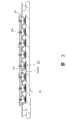
图3为图1中发光二极管灯具的截面图。FIG. 3 is a cross-sectional view of the LED lamp in FIG. 1 .
具体实施方式Detailed ways
请参考图1-3,本发明一优选实施例中的发光二极管灯具用于为室内和户外一些特定的场合提供柔和均匀的照明灯光,该发光二极管灯具包括一基板10、安装在基板10上的若干发光二极管模组20和安装在基板10顶面并罩设发光二极管模组20的一导光模组30。Please refer to Fig. 1-3, the light-emitting diode light fixture in a preferred embodiment of the present invention is used for providing soft and uniform illumination light for indoor and outdoor some special occasions, and this light-emitting diode light fixture comprises a
上述基板10由导热性能良好的材料如铝、铜等制成,其大致呈矩形,基板10上开设有若干列与基板10两侧平行的安装孔12,所述每一列安装孔12相互等距间隔,其最靠外侧的两列安装孔12用于安装导光模组30,其余的安装孔12每一列对应一发光二极管模组20。The above-mentioned
上述每一发光二极管模组20包括一长矩形电路板22和安装在电路板22上的若干发光二极管元件24。上述发光二极管元件24沿电路板22长度方向等距间隔排列,且电路板22在部分发光二极管元件24之间开设有穿孔26,所述穿孔26用于供螺钉(图未示)穿过与基板10上相对应的一列安装孔12配合,从而将发光二极管模组20稳固贴设到基板10顶面。Each LED module 20 includes a long
上述导光模组30包括一罩设于发光二极管模组20上方的一安装板32、安装在安装板32上并正对发光二极管模组20的若干导光棒34和将所述导光棒34锁定到安装板32上的二固定片36。该安装板32为与基板10对应的矩形板体,安装板32上对应贴设于基板10上的发光二极管模组20的发光二极管元件24设置有若干导光单元324,每一导光单元324对应一发光二极管元件24,每一导光单元324具有一由安装板32向下延伸并同时向内收拢的导光部3240。所述导光部3240呈四棱台状,其底部开口3242小于顶部开口(图未标),发光二极管元件24自下向上穿过开口3242而插入导光部3240内并被导光部3240的壁面所环绕。所述安装板32相对两侧处开设有若干通孔320,并在安装板32底面向下延设有若干分别与通孔320连通的固定筒322,所述固定孔322底端抵压在基板10上,且固定件(图未示)穿过安装板32的通孔320及对应的固定筒322与基板10最外侧的相对两列安装孔12配合而将安装板32以及整个导光模组30固定到基板10上。该安装板32靠近其另外相对两侧处向上凸设有若干固定凸部326,每一固定凸部326由其内侧面及顶面向内凹设有凹槽3262,且每相隔的一固定凸部326在凹槽3262的一侧开设有配合孔3260。The above-mentioned light guide module 30 includes a
上述导光棒34两端的顶部向下凹陷形成二卡入部340,所述卡入部340正好卡入安装板32对应固定凸部326的凹槽3262内,并使每一导光棒34正对每一发光管模组20的一列发光二极管元件24中心的连线的正上方。请特别参阅图3,所述导光棒34厚度由靠近发光二极管模组20的一端向远离发光二极管模组20的另一端递增,从而使导光棒34的截面呈三角形或梯形。The tops of both ends of the
上述二固定片36上开设有若干通孔360,以供螺钉100穿过对应的通孔360与安装板32固定凸部326的配合孔3260螺合,而将导光棒34两端的卡入部340锁在固定凸部326的凹槽3262内,进而将导光棒34安装固定。The above two
上述发光二极管灯具的设置有与每一发光二极管模组20的中心正对的导光棒34,所述导光棒34的厚度由靠近发光二极管模组20的一端向远离发光二极管模组20的另一端递增,从使发光二极管模组20产生的照明光照射在导光棒34两侧的斜面上而反射到发光二极管模组20中心的周围,而不会在发光二极管模组20中心聚集,进而使发光二极管模组20能够提供强度均匀的照明光。The light-emitting diode lamp above is provided with a light-guiding
Claims (7)
Priority Applications (2)
| Application Number | Priority Date | Filing Date | Title |
|---|---|---|---|
| CN2008100681110ACN101614367B (en) | 2008-06-25 | 2008-06-25 | Light-emitting diode lamp |
| US12/241,061US7794099B2 (en) | 2008-06-25 | 2008-09-30 | LED lamp |
Applications Claiming Priority (1)
| Application Number | Priority Date | Filing Date | Title |
|---|---|---|---|
| CN2008100681110ACN101614367B (en) | 2008-06-25 | 2008-06-25 | Light-emitting diode lamp |
Publications (2)
| Publication Number | Publication Date |
|---|---|
| CN101614367A CN101614367A (en) | 2009-12-30 |
| CN101614367Btrue CN101614367B (en) | 2011-12-28 |
Family
ID=41447158
Family Applications (1)
| Application Number | Title | Priority Date | Filing Date |
|---|---|---|---|
| CN2008100681110AExpired - Fee RelatedCN101614367B (en) | 2008-06-25 | 2008-06-25 | Light-emitting diode lamp |
Country Status (2)
| Country | Link |
|---|---|
| US (1) | US7794099B2 (en) |
| CN (1) | CN101614367B (en) |
Families Citing this family (9)
| Publication number | Priority date | Publication date | Assignee | Title |
|---|---|---|---|---|
| DE102009016256A1 (en)* | 2009-04-03 | 2010-10-14 | Vishay Electronic Gmbh | Exterior lighting unit |
| US8021017B2 (en)* | 2009-05-21 | 2011-09-20 | Sheng-Hsiung Cheng | LED lamp having improved heat dissipation structure |
| TWI417478B (en)* | 2010-08-19 | 2013-12-01 | Delta Electronics Inc | Lamp module |
| DE102011078287A1 (en)* | 2011-06-29 | 2013-01-03 | Zumtobel Lighting Gmbh | Light control element |
| DE202012103452U1 (en)* | 2012-09-11 | 2013-12-12 | Zumtobel Lighting Gmbh | Grid lamp with LED light sources |
| EP3147559B1 (en)* | 2015-09-28 | 2019-01-30 | Holophane Europe Ltd. | Louver for led light engines |
| US10101005B2 (en) | 2016-08-03 | 2018-10-16 | Abl Ip Holding Llc | Light shield |
| US9741273B1 (en) | 2016-08-10 | 2017-08-22 | Jeffrey A. Curtis | Illuminated assemblies and methods of manufacture thereof |
| CN106647036A (en)* | 2017-01-25 | 2017-05-10 | 北海星沅电子科技有限公司 | Double-light source liquid crystal module |
Citations (1)
| Publication number | Priority date | Publication date | Assignee | Title |
|---|---|---|---|---|
| DE202006019085U1 (en)* | 2006-12-16 | 2007-02-22 | Baars, Georg | A method for providing a linear illumination from a point source has reflectors set at right angles and mirrors also set at right angles positioned immediately before an LED light source |
Family Cites Families (8)
| Publication number | Priority date | Publication date | Assignee | Title |
|---|---|---|---|---|
| US7080933B2 (en)* | 2004-05-28 | 2006-07-25 | J. S. Technology Co., Ltd. | BLU and module using the BLU |
| KR100716989B1 (en)* | 2004-12-23 | 2007-05-10 | 삼성전자주식회사 | Backlight system and LCD using the same |
| TWI313775B (en)* | 2005-01-06 | 2009-08-21 | Au Optronics Corp | Backlight module and illumination device thereof |
| JP2006252958A (en)* | 2005-03-10 | 2006-09-21 | Sharp Corp | Illumination device and liquid crystal display device including the same |
| TWI363219B (en)* | 2005-09-05 | 2012-05-01 | Hon Hai Prec Ind Co Ltd | Direct type backlight module |
| KR101222152B1 (en)* | 2006-02-06 | 2013-01-14 | 삼성디스플레이 주식회사 | Backlight assembly and display device having the same |
| KR101252846B1 (en)* | 2006-04-28 | 2013-04-09 | 엘지디스플레이 주식회사 | Backlight assembly and liquid crystal display device having the same |
| US7661862B2 (en)* | 2006-12-07 | 2010-02-16 | Skc Haas Display Films Co., Ltd. | LCD display backlight using elongated illuminators |
- 2008
- 2008-06-25CNCN2008100681110Apatent/CN101614367B/ennot_activeExpired - Fee Related
- 2008-09-30USUS12/241,061patent/US7794099B2/ennot_activeExpired - Fee Related
Patent Citations (1)
| Publication number | Priority date | Publication date | Assignee | Title |
|---|---|---|---|---|
| DE202006019085U1 (en)* | 2006-12-16 | 2007-02-22 | Baars, Georg | A method for providing a linear illumination from a point source has reflectors set at right angles and mirrors also set at right angles positioned immediately before an LED light source |
Also Published As
| Publication number | Publication date |
|---|---|
| US20090323328A1 (en) | 2009-12-31 |
| CN101614367A (en) | 2009-12-30 |
| US7794099B2 (en) | 2010-09-14 |
Similar Documents
| Publication | Publication Date | Title |
|---|---|---|
| CN101614367B (en) | Light-emitting diode lamp | |
| EP2134569B1 (en) | Lighting assembly having a heat dissipating housing | |
| CN102165251B (en) | LED lighting device | |
| CN101566320B (en) | Light-emitting diode lamp | |
| EP2261550A2 (en) | Knock-down led lighting fixtures | |
| JP3146172U (en) | LED lighting fixture | |
| KR20090017916A (en) | Prefabricated LED Lighting Structure | |
| CN101545606B (en) | LED lamps | |
| KR20090006720A (en) | High-performance LED street light and its body frame | |
| KR101369422B1 (en) | Light emitting diode lighting lamp | |
| KR20100138836A (en) | Lighting equipment | |
| CN106716010A (en) | Led lighting device | |
| JP2012204162A (en) | Lighting device and lighting fixture | |
| KR20090010850U (en) | Lighting device using LED as light source | |
| KR101256865B1 (en) | Led lamp for lighting | |
| JP2013077400A (en) | Lighting device | |
| US8789976B2 (en) | Integrated multi-layered illuminating unit and integrated multi-layered illuminating assembling unit | |
| JP5835560B2 (en) | Lighting device | |
| KR200463715Y1 (en) | Assembling structure of the illuminators for medical usage | |
| KR200455629Y1 (en) | LED lamp | |
| KR101623708B1 (en) | A led lighting structure | |
| KR101404302B1 (en) | Led illumination apparatus and mathod of manufacturing the same | |
| KR101083034B1 (en) | Luminaire | |
| KR100997917B1 (en) | LED lighting device | |
| TWI397655B (en) | Led lamp |
Legal Events
| Date | Code | Title | Description |
|---|---|---|---|
| C06 | Publication | ||
| PB01 | Publication | ||
| C10 | Entry into substantive examination | ||
| SE01 | Entry into force of request for substantive examination | ||
| C14 | Grant of patent or utility model | ||
| GR01 | Patent grant | ||
| ASS | Succession or assignment of patent right | Owner name:SHENZHEN QICHUANGMEI TECHNOLOGY CO., LTD. Free format text:FORMER OWNER: FUHUAI (SHENZHENG) PRECISION INDUSTRY CO., LTD. Effective date:20141125 Owner name:STATE GRID TIANJIN ELECTRIC POWER COMPANY Free format text:FORMER OWNER: SHENZHEN QICHUANGMEI TECHNOLOGY CO., LTD. Effective date:20141125 Free format text:FORMER OWNER: HONGZHUN PRECISION INDUSTRY CO., LTD. Effective date:20141125 | |
| C41 | Transfer of patent application or patent right or utility model | ||
| COR | Change of bibliographic data | Free format text:CORRECT: ADDRESS; FROM: 518109 SHENZHEN, GUANGDONG PROVINCE TO: 518000 SHENZHEN, GUANGDONG PROVINCE Free format text:CORRECT: ADDRESS; FROM: 518000 SHENZHEN, GUANGDONG PROVINCE TO: 300010 HEBEI, TIANJIN | |
| TR01 | Transfer of patent right | Effective date of registration:20141125 Address after:300010 Tianjin city Hebei District Hebei District Wujing Road No. 39 Patentee after:STATE GRID TIANJIN ELECTRIC POWER Co. Address before:518000 Guangdong city of Shenzhen province Futian District Che Kung Temple Tairan nine road Haisong building B block 1205 Patentee before:Shenzhen Qichuangmei Technology Co.,Ltd. Effective date of registration:20141125 Address after:518000 Guangdong city of Shenzhen province Futian District Che Kung Temple Tairan nine road Haisong building B block 1205 Patentee after:Shenzhen Qichuangmei Technology Co.,Ltd. Address before:518109 Guangdong city of Shenzhen province Baoan District Longhua Town Industrial Zone tabulaeformis tenth East Ring Road No. 2 two Patentee before:Fuzhun Precision Industry (Shenzhen) Co.,Ltd. Patentee before:Foxconn Technology Co.,Ltd. | |
| CF01 | Termination of patent right due to non-payment of annual fee | ||
| CF01 | Termination of patent right due to non-payment of annual fee | Granted publication date:20111228 Termination date:20190625 |