CN101614237A - Hinge structure - Google Patents
Hinge structureDownload PDFInfo
- Publication number
- CN101614237A CN101614237ACN200810302399.3ACN200810302399ACN101614237ACN 101614237 ACN101614237 ACN 101614237ACN 200810302399 ACN200810302399 ACN 200810302399ACN 101614237 ACN101614237 ACN 101614237A
- Authority
- CN
- China
- Prior art keywords
- hinge structure
- fixing
- pivot
- bracket
- piece
- Prior art date
- Legal status (The legal status is an assumption and is not a legal conclusion. Google has not performed a legal analysis and makes no representation as to the accuracy of the status listed.)
- Pending
Links
Images


Classifications
- G—PHYSICS
- G06—COMPUTING OR CALCULATING; COUNTING
- G06F—ELECTRIC DIGITAL DATA PROCESSING
- G06F1/00—Details not covered by groups G06F3/00 - G06F13/00 and G06F21/00
- G06F1/16—Constructional details or arrangements
- G06F1/1613—Constructional details or arrangements for portable computers
- G06F1/1633—Constructional details or arrangements of portable computers not specific to the type of enclosures covered by groups G06F1/1615 - G06F1/1626
- G06F1/1675—Miscellaneous details related to the relative movement between the different enclosures or enclosure parts
- G06F1/1681—Details related solely to hinges
- G—PHYSICS
- G06—COMPUTING OR CALCULATING; COUNTING
- G06F—ELECTRIC DIGITAL DATA PROCESSING
- G06F1/00—Details not covered by groups G06F3/00 - G06F13/00 and G06F21/00
- G06F1/16—Constructional details or arrangements
- G06F1/1613—Constructional details or arrangements for portable computers
- G06F1/1615—Constructional details or arrangements for portable computers with several enclosures having relative motions, each enclosure supporting at least one I/O or computing function
- G06F1/1616—Constructional details or arrangements for portable computers with several enclosures having relative motions, each enclosure supporting at least one I/O or computing function with folding flat displays, e.g. laptop computers or notebooks having a clamshell configuration, with body parts pivoting to an open position around an axis parallel to the plane they define in closed position
- H—ELECTRICITY
- H04—ELECTRIC COMMUNICATION TECHNIQUE
- H04M—TELEPHONIC COMMUNICATION
- H04M1/00—Substation equipment, e.g. for use by subscribers
- H04M1/02—Constructional features of telephone sets
- H04M1/0202—Portable telephone sets, e.g. cordless phones, mobile phones or bar type handsets
- H04M1/0206—Portable telephones comprising a plurality of mechanically joined movable body parts, e.g. hinged housings
- H04M1/0208—Portable telephones comprising a plurality of mechanically joined movable body parts, e.g. hinged housings characterized by the relative motions of the body parts
- H04M1/0214—Foldable telephones, i.e. with body parts pivoting to an open position around an axis parallel to the plane they define in closed position
- H04M1/0216—Foldable in one direction, i.e. using a one degree of freedom hinge
- E—FIXED CONSTRUCTIONS
- E05—LOCKS; KEYS; WINDOW OR DOOR FITTINGS; SAFES
- E05D—HINGES OR SUSPENSION DEVICES FOR DOORS, WINDOWS OR WINGS
- E05D11/00—Additional features or accessories of hinges
- E05D11/06—Devices for limiting the opening movement of hinges
- E—FIXED CONSTRUCTIONS
- E05—LOCKS; KEYS; WINDOW OR DOOR FITTINGS; SAFES
- E05D—HINGES OR SUSPENSION DEVICES FOR DOORS, WINDOWS OR WINGS
- E05D11/00—Additional features or accessories of hinges
- E05D11/08—Friction devices between relatively-movable hinge parts
- E05D11/087—Friction devices between relatively-movable hinge parts with substantially axial friction, e.g. friction disks
- E—FIXED CONSTRUCTIONS
- E05—LOCKS; KEYS; WINDOW OR DOOR FITTINGS; SAFES
- E05Y—INDEXING SCHEME ASSOCIATED WITH SUBCLASSES E05D AND E05F, RELATING TO CONSTRUCTION ELEMENTS, ELECTRIC CONTROL, POWER SUPPLY, POWER SIGNAL OR TRANSMISSION, USER INTERFACES, MOUNTING OR COUPLING, DETAILS, ACCESSORIES, AUXILIARY OPERATIONS NOT OTHERWISE PROVIDED FOR, APPLICATION THEREOF
- E05Y2999/00—Subject-matter not otherwise provided for in this subclass
Landscapes
- Engineering & Computer Science (AREA)
- Computer Hardware Design (AREA)
- Theoretical Computer Science (AREA)
- Physics & Mathematics (AREA)
- Human Computer Interaction (AREA)
- General Engineering & Computer Science (AREA)
- General Physics & Mathematics (AREA)
- Signal Processing (AREA)
- Mathematical Physics (AREA)
- Pivots And Pivotal Connections (AREA)
Abstract
Translated fromChinese
Description
Translated fromChinese技术领域technical field
本发明是关于一种铰链结构,尤其是关于一种具有限位单元的铰链结构。The invention relates to a hinge structure, in particular to a hinge structure with a limiting unit.
背景技术Background technique
目前,笔记本电脑等便携式电子装置一般包括一个本体和一个盖体,显示屏设于盖体上,为使显示屏具有较佳视角,通常需要通过铰链结构将盖体可旋转地连接至本体上。At present, portable electronic devices such as notebook computers generally include a body and a cover, and a display screen is disposed on the cover. In order to make the display screen have a better viewing angle, it is usually necessary to rotatably connect the cover to the body through a hinge structure.
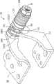
请参阅图1,一种现有的铰链结构10,包括一个枢轴11、一个固定支架12、一个旋转支架13、一个限位件14、一个固定件15、一个转动定位件16、一个弹片组17及一个螺母18。该枢轴11的横截面为非圆形,其一端形成有凸缘111,另一端形成有一个螺纹部112。该固定支架12上开设有一个供枢轴11穿设的圆形枢转孔121,并在该枢转孔121附近形成有一个限位凸起122。该固定支架12还于该限位凸起122的下方形成有一个固定孔123。该旋转支架13上开设有与枢轴11端部配合的非圆变形孔131。该限位件14的中心开设有一个与枢轴11配合的非圆变形孔141,侧壁上开设有一个限位槽142。该固定件15的一端开设有一个圆孔151,另一端形成有一个凸柱152。该固定件15的一端面上还形成有两个相对的凸起(图未示)。该转动定位件16的中心开设有一个与枢轴11配合的非圆变形孔161,一端面上开设有两个相对的凹槽162,以与固定件15上的凸起配合。该限位件14、固定件15及转动定位件16一般由粉末冶金材料制成,以使其具有较高的硬度及耐磨性,而固定支架12及旋转支架13通常由一般硬度的合金材料制成,以降低制造成本。Please refer to Fig. 1, a kind of existing
组装时,将枢轴11具有螺纹部112的一端穿过限位件14上的非圆变形孔141,固定支架12上的枢转孔121,固定件15上的圆孔151,转动定位件16上的非圆变形孔161,以及弹片组17后,与螺母18相螺合,然后将旋转支架13卡固于枢轴11设有凸缘111的端部,固定件15上的凸柱152卡入固定支架12的固定孔123。此时,该旋转支架13、限位件14、转动定位件16与枢轴11为非可转动连接。When assembling, pass one end of the
工作时,该旋转支架13相对固定支架12旋转,以带动枢轴11旋转,从而带动限位件14及转动定位件16旋转。该固定支架12上的限位凸起122于限位件14的限位槽142中滑动,以限制旋转支架13的转动角度。该转动定位件16与固定件15配合以使旋转支架13转过一定角度后定位。During operation, the rotating
然而,该限位件14是由粉末冶金材料制成,而固定支架12是由一般硬度的合金材料制成,且限位凸起122一般是通过冲压工艺在固定支架12上直接形成,所以限位件14多次旋转后易造成固定支架12上的限位凸起122被磨损,从而影响旋转支架13相对固定支架12的旋转角度范围。因此,该种铰链结构10的使用寿命通常较短。另外,如果将整个固定支架12采用粉末冶金材料制成,虽然可使限位凸起122具有较高的硬度和耐磨性,但会导致整个铰链结构10的制造成本较高。However, the
发明内容Contents of the invention
鉴于以上内容,有必要提供一种制造成本较低,但具较长使用寿命的铰链结构。In view of the above, it is necessary to provide a hinge structure with low manufacturing cost and long service life.
一种铰链结构,包括一个枢轴、一个旋转支架、一个固定支架、一个固定件、一个限位件及一个锁合件,该旋转支架及限位件与枢轴为非可转动连接,该固定支架及固定件与枢轴为可转动连接,该固定件与固定支架固定连接,且该固定件上开设有一个限位槽,该限位件的边缘朝向固定件延伸有一个限位片,该限位片用于在固定件的限位槽中滑动,以限制旋转支架相对固定支架的旋转角度范围。A hinge structure, comprising a pivot, a rotating bracket, a fixed bracket, a fixing piece, a limiting piece and a locking piece, the rotating bracket and the limiting piece are non-rotatably connected to the pivot, the fixed The bracket and the fixing part are rotatably connected to the pivot, the fixing part is fixedly connected to the fixing bracket, and a limiting groove is opened on the fixing part, and a limiting piece is extended from the edge of the limiting part toward the fixing part. The limiting piece is used for sliding in the limiting groove of the fixing part, so as to limit the range of the rotation angle of the rotating bracket relative to the fixed bracket.
相较于现有技术,所述铰链结构通过限位件上的限位片与固定件的限位槽配合,以限制旋转支架相对固定支架的旋转角度,由于该固定件一般由粉末冶金材料制成,所以该固定件的限位槽的侧壁具有较好的硬度及耐磨性能,可在长期使用过程中使该旋转支架相对固定支架的旋转角度范围保持稳定,从而提高铰链结构的使用寿命。而且,该固定支架仅由一般硬度的合金材料制成即可,以使该铰链结构具有较低的制造成本。Compared with the prior art, the hinge structure cooperates with the limiting groove of the fixing piece through the limiting piece on the limiting piece to limit the rotation angle of the rotating bracket relative to the fixed bracket. Since the fixing piece is generally made of powder metallurgy material Therefore, the side wall of the limiting groove of the fixing part has good hardness and wear resistance, which can keep the rotation angle range of the rotating bracket relative to the fixed bracket stable during long-term use, thereby improving the service life of the hinge structure . Moreover, the fixing bracket is only made of alloy material with general hardness, so that the hinge structure has a lower manufacturing cost.
附图说明Description of drawings
图1是一种现有铰链结构的立体图;Fig. 1 is a perspective view of an existing hinge structure;
图2是本发明较佳实施方式的铰链结构的立体图;Fig. 2 is a perspective view of a hinge structure in a preferred embodiment of the present invention;
图3是图2所示铰链结构的立体分解图;Fig. 3 is a three-dimensional exploded view of the hinge structure shown in Fig. 2;
图4是图2所示铰链结构另一视角的立体分解图;Fig. 4 is a three-dimensional exploded view of another viewing angle of the hinge structure shown in Fig. 2;
图5是图2所示的铰链结构的旋转支架相对固定支架转过一定角度后的立体图。Fig. 5 is a perspective view of the rotating bracket of the hinge structure shown in Fig. 2 after a certain angle has been rotated relative to the fixed bracket.
具体实施方式Detailed ways
下面将结合附图及实施例对本发明的铰链结构做进一步详细说明。The hinge structure of the present invention will be further described in detail with reference to the accompanying drawings and embodiments.
请参阅图2至图4,本较佳实施方式提供一种铰链结构30,其包括一个枢轴31、一个旋转支架32、一个固定支架33、一个限位件34、一个固定件35、一个转动定位件36、一个弹片组37、两个摩擦片381、两个垫片382及一个锁合件39。Referring to Fig. 2 to Fig. 4, this preferred embodiment provides a
该枢轴31的横截面为非圆形,其一端形成有圆盘状凸缘311,另一端形成有一个螺纹部312。该凸缘311进一步向外延伸有一个插接部314。The cross section of the
该旋转支架32包括一个基板321,其上开设有多个固定孔3211。该基板321的一侧延伸有一个弧形定位片322,该弧形定位片322远离基板321的一端开设有一个与枢轴31的插接部314配合的非圆变形孔3221。The rotating
该固定支架33包括一个固定板331及一个由该固定板331一侧垂直延伸形成的支撑板332。该固定板331上开设有多个固定孔3311。该支撑板332远离固定板331的端部开设有一个枢转孔3321,中部开设有一个卡合孔3322。该支撑板332远离固定板331的末端还开设有一个凹口3323。The
该限位件34包括一个大致为圆形的本体341。该本体341的中心开设有一个非圆变形孔342,边缘上垂直延伸有一个限位片343。该本体341的端面上还开设有多个油槽344。The
该固定件35包括一个大致为圆盘状的枢转部351及一个由该枢转部351延伸形成的连接部352。该枢转部351的中心开设有一个圆形轴孔3511,边缘处开设有一个限位槽3512。该枢转部351远离限位槽3512的端面上形成有两个相对的定位凸起3513。该枢转部351上还开设有多个油槽3514。该连接部352上延伸有一个凸柱3521。The
该转动定位件36大致为圆盘状,其中心开设有一个非圆变形孔361。该转动定位件36的一端面上开设有两个相对的定位凹槽362,该定位凹槽362用于与固定件35上的定位凸起3513相配合。该转动定位件36的端面上还开设有多个油槽363。The rotating
该限位件34、固定件35及转动定位件36均由粉末冶金材料制成。The
该弹片组37由多个碟形弹片叠合而成。The
该摩擦片381的中心开设有一个圆形通孔3811,边缘处垂直延伸有一个定位片3812,该定位片3812用于插入固定支架33上的凹口3323中。该摩擦片381的端面上开设有多个油槽3813。A circular through
该垫片382中心开设有一个非圆变形孔3821,其端面上开设有多个油槽3822。A
该锁合件39在本实施例中为一个与枢轴31的螺纹部312配合的螺母。In this embodiment, the locking
装配该铰链结构30时,将枢轴31具有螺纹部312的一端穿过一个垫片382、一个摩擦片381、固定支架33上的枢转孔3321、另一个摩擦片381、限位件34上的非圆变形孔342、固定件35的轴孔3511、转动定位件36的非圆变形孔361、弹片组37及另一个垫片382,与螺母39相螺合。接着将枢轴31的插接部314卡入旋转支架32的非圆变形孔3221中。此时,旋转支架32、限位件34、转动定位件36及垫片382与枢轴31为非可转动连接,该限位件34的限位片343位于固定件35的限位槽3512中。然后将固定件35上的凸柱3521卡入固定支架33上的卡合孔3322中,并推动转动定位件36,以使固定件35上的定位凸起3513卡入转动定位件36的定位凹槽362中。接着将两个摩擦片381上的定位片3812分别插入固定支架33的凹口3323中。调节该螺母39,以使弹片组37产生轴向的弹力作用于该转动定位件36。When assembling the
请参阅图2至图5,打开该铰链结构30时,推动旋转支架32的基板321沿远离固定支架33的方向旋转,该枢轴31将在旋转支架32的带动下旋转,从而带动枢轴31上的限位件34及转动定位件36旋转。当限位件34上的限位片343与固定件35的限位槽3512的端部相抵时,该旋转支架32不可继续转动。此时,该旋转支架32相对固定支架33处于最大打开角度。在此过程中,可于任意位置停止对旋转支架32施力,从而使旋转支架32停止于任意位置。关闭该铰链结构30时,推动旋转支架32的基板321沿靠近固定支架33的方向旋转,该枢轴31将在旋转支架32的带动下旋转,从而带动枢轴31上的限位件34及转动定位件36旋转。由于转动定位件36受到弹片组37的轴向弹力作用,所以可驱使转动定位件36上的定位凹槽362扣合于固定件35的定位凸起3513上,以使旋转支架32相对固定支架33定位。Please refer to Figures 2 to 5, when the
该铰链结构30应用于电子装置时,其旋转支架32及固定支架33分别与电子装置的盖体及本体相连即可,从而可使该电子装置的盖体可相对本体打开一定角度,也可使电子装置的盖体在闭合过程中与本体自动锁紧。When the
该铰链结构30通过限位件34上的限位片343与固定件35的限位槽3512配合,以限制旋转支架32相对固定支架33的旋转角度范围,由于该固定件35一般由粉末冶金材料制成,所以该固定件35的限位槽3512的侧壁具有较好的耐磨性能,可在长期使用过程中使该旋转支架32相对固定支架33的旋转角度范围保持稳定,从而提高铰链结构30的使用寿命。而且,该固定支架33与固定件35相对的端面上贴附有摩擦片381,可防止限位件34在旋转支架32的转动过程中对固定支架33进行摩擦,因此,该固定支架仍33可由一般硬度的合金材料制成,从而使该铰链结构30的制造成本较低,且同时具有较长的使用寿命。另外,该限位件34、转动定位件36、固定件35、摩擦片381及垫片382上均开设有油槽,可减小各元件在转动过程中的磨损,从而进一步增加了铰链结构30的使用寿命。The
可以理解,该铰链结构30的转动定位件36上也可不形成定位凹槽362,而是形成多个定位凸起,然后在固定件35上形成与该多个定位凸起配合的多个定位凹槽即可。而且,该转动定位件36上的定位凹槽362及固定件35上的定位凸起3513也可相应设置一个、三个或三个以上,从而增加旋转支架32在转动过程中的定位位置。另外,该固定件35及限位件34也可由其他具有高硬度及较佳耐磨性能的材料制成,如金属压铸材料等。弹片组37也可由其他弹性件,如弹簧等代替。It can be understood that the
Claims (10)
Translated fromChinesePriority Applications (2)
| Application Number | Priority Date | Filing Date | Title |
|---|---|---|---|
| CN200810302399.3ACN101614237A (en) | 2008-06-27 | 2008-06-27 | Hinge structure |
| US12/261,225US20090320245A1 (en) | 2008-06-27 | 2008-10-30 | Hinge assembly |
Applications Claiming Priority (1)
| Application Number | Priority Date | Filing Date | Title |
|---|---|---|---|
| CN200810302399.3ACN101614237A (en) | 2008-06-27 | 2008-06-27 | Hinge structure |
Publications (1)
| Publication Number | Publication Date |
|---|---|
| CN101614237Atrue CN101614237A (en) | 2009-12-30 |
Family
ID=41445742
Family Applications (1)
| Application Number | Title | Priority Date | Filing Date |
|---|---|---|---|
| CN200810302399.3APendingCN101614237A (en) | 2008-06-27 | 2008-06-27 | Hinge structure |
Country Status (2)
| Country | Link |
|---|---|
| US (1) | US20090320245A1 (en) |
| CN (1) | CN101614237A (en) |
Cited By (6)
| Publication number | Priority date | Publication date | Assignee | Title |
|---|---|---|---|---|
| CN102200167A (en)* | 2010-03-24 | 2011-09-28 | 鸿富锦精密工业(深圳)有限公司 | Hinge structure |
| CN105649445A (en)* | 2016-03-19 | 2016-06-08 | 泰州市亚泰电力机车配件有限公司 | Wearproof heavy hinge structure |
| CN109356871A (en)* | 2015-09-07 | 2019-02-19 | 珠海格力电器股份有限公司 | Electric fan head positioning structure and electric fan |
| CN111637818A (en)* | 2020-06-29 | 2020-09-08 | 中核华辰建筑工程有限公司 | A plate thickness gauge |
| CN112044315A (en)* | 2020-08-27 | 2020-12-08 | 杭州怡田工具制造有限公司 | Agitating unit convenient to control load |
| CN112762089A (en)* | 2021-01-21 | 2021-05-07 | 上海徕木电子股份有限公司 | Rotating shaft capable of being limited and controlled by any stroke angle and wireless charger |
Families Citing this family (7)
| Publication number | Priority date | Publication date | Assignee | Title |
|---|---|---|---|---|
| CN101737416B (en)* | 2008-11-04 | 2012-03-14 | 鸿富锦精密工业(深圳)有限公司 | Hinge structure |
| US8082626B2 (en)* | 2009-05-25 | 2011-12-27 | Sinher Technology Inc. | Hinge for anchoring and automatic closing |
| US8196262B2 (en)* | 2010-01-26 | 2012-06-12 | Hon Hai Precision Industry Co., Ltd. | Hinge |
| US20140168928A1 (en)* | 2012-12-14 | 2014-06-19 | Chung-Yu Lee | Pivoting Mechanism and Electronic Device Thereof |
| TWI612873B (en)* | 2016-06-22 | 2018-01-21 | 緯創資通股份有限公司 | Pivoting structure and portable electronic device having pivoting structure |
| KR102517173B1 (en)* | 2018-10-23 | 2023-04-03 | 삼성전자 주식회사 | Electronic device incluing stand member |
| JP7749968B2 (en)* | 2021-07-30 | 2025-10-07 | マックス株式会社 | stapler |
Family Cites Families (9)
| Publication number | Priority date | Publication date | Assignee | Title |
|---|---|---|---|---|
| DE69112102T2 (en)* | 1990-03-07 | 1996-04-04 | Matsushita Electric Ind Co Ltd | Opening and closing mechanism. |
| JP3798899B2 (en)* | 1998-01-27 | 2006-07-19 | 加藤電機株式会社 | Tilt hinge |
| US20050081334A1 (en)* | 2003-10-15 | 2005-04-21 | Tai Wen H. | Hinge structure |
| TWM281387U (en)* | 2005-08-17 | 2005-11-21 | Shin Zu Shing Co Ltd | Hinge having positioning and limiting functions |
| TWM296586U (en)* | 2006-01-26 | 2006-08-21 | Jarllytec Co Ltd | Structure of rotary shaft with automatic latching function |
| US7669286B2 (en)* | 2006-01-31 | 2010-03-02 | Shin Zu Shing Co., Ltd. | Pivotal hinge |
| US20070199179A1 (en)* | 2006-02-28 | 2007-08-30 | Ting-Hsien Wang | Hinge with less noise |
| TW200920238A (en)* | 2007-10-25 | 2009-05-01 | Jarllytec Co Ltd | Wrapped shaft structure with automatic lock function |
| TW200934962A (en)* | 2008-02-05 | 2009-08-16 | Leohab Entpr Co Ltd | Pivot with increased load |
- 2008
- 2008-06-27CNCN200810302399.3Apatent/CN101614237A/enactivePending
- 2008-10-30USUS12/261,225patent/US20090320245A1/ennot_activeAbandoned
Cited By (7)
| Publication number | Priority date | Publication date | Assignee | Title |
|---|---|---|---|---|
| CN102200167A (en)* | 2010-03-24 | 2011-09-28 | 鸿富锦精密工业(深圳)有限公司 | Hinge structure |
| CN109356871A (en)* | 2015-09-07 | 2019-02-19 | 珠海格力电器股份有限公司 | Electric fan head positioning structure and electric fan |
| CN105649445A (en)* | 2016-03-19 | 2016-06-08 | 泰州市亚泰电力机车配件有限公司 | Wearproof heavy hinge structure |
| CN111637818A (en)* | 2020-06-29 | 2020-09-08 | 中核华辰建筑工程有限公司 | A plate thickness gauge |
| CN112044315A (en)* | 2020-08-27 | 2020-12-08 | 杭州怡田工具制造有限公司 | Agitating unit convenient to control load |
| CN112044315B (en)* | 2020-08-27 | 2022-08-02 | 杭州怡田工具制造有限公司 | Agitating unit convenient to control load |
| CN112762089A (en)* | 2021-01-21 | 2021-05-07 | 上海徕木电子股份有限公司 | Rotating shaft capable of being limited and controlled by any stroke angle and wireless charger |
Also Published As
| Publication number | Publication date |
|---|---|
| US20090320245A1 (en) | 2009-12-31 |
Similar Documents
| Publication | Publication Date | Title |
|---|---|---|
| CN101614236B (en) | Hinge structure | |
| CN101614237A (en) | Hinge structure | |
| US7526835B2 (en) | Stable hinge | |
| US8069534B2 (en) | Hinge assembly | |
| US7870644B2 (en) | Hinge and interference assembly thereof | |
| CN101684837A (en) | Hinge structure | |
| CN201513461U (en) | hub | |
| US20090235489A1 (en) | Sheath Type Rotating Axel Structure with Automatic Locking Mechanism | |
| US8291549B2 (en) | Hinge mechanism | |
| US7621021B2 (en) | Transversely movable hinge | |
| CN101660566B (en) | Hinge structure | |
| CN101614238B (en) | Hinge structure | |
| US7533449B2 (en) | Hinge to improve panel stability | |
| US20110265287A1 (en) | Hinge assembly | |
| CN101105198A (en) | Hinge mechanism | |
| CN101725622A (en) | Hinge structure | |
| US20090217486A1 (en) | Hinge device and electronic apparatus | |
| US8891248B2 (en) | Angle-adjustable support with pivot mechanism | |
| US20100024171A1 (en) | Hinge and collapsible device utilizing the same | |
| CN201391539Y (en) | hub | |
| CN201696463U (en) | Concave-convex wheel structure of pivot device | |
| TWI345946B (en) | Hinge assembly | |
| CN101725625B (en) | Hinge structure | |
| KR20070075084A (en) | Hinge device | |
| JP2589482Y2 (en) | Tilt hinge for OA equipment |
Legal Events
| Date | Code | Title | Description |
|---|---|---|---|
| C06 | Publication | ||
| PB01 | Publication | ||
| C10 | Entry into substantive examination | ||
| SE01 | Entry into force of request for substantive examination | ||
| C12 | Rejection of a patent application after its publication | ||
| RJ01 | Rejection of invention patent application after publication | Open date:20091230 |