CN101614154A - Carbonization and gasification of biomass and power plant - Google Patents
Carbonization and gasification of biomass and power plantDownload PDFInfo
- Publication number
- CN101614154A CN101614154ACN200910150227ACN200910150227ACN101614154ACN 101614154 ACN101614154 ACN 101614154ACN 200910150227 ACN200910150227 ACN 200910150227ACN 200910150227 ACN200910150227 ACN 200910150227ACN 101614154 ACN101614154 ACN 101614154A
- Authority
- CN
- China
- Prior art keywords
- gasifier
- biomass
- gas
- temperature
- gasification
- Prior art date
- Legal status (The legal status is an assumption and is not a legal conclusion. Google has not performed a legal analysis and makes no representation as to the accuracy of the status listed.)
- Granted
Links
- 238000002309gasificationMethods0.000titleclaimsabstractdescription205
- 239000002028BiomassSubstances0.000titleclaimsabstractdescription162
- 238000003763carbonizationMethods0.000titleclaimsabstractdescription130
- 239000007789gasSubstances0.000claimsabstractdescription238
- 239000000446fuelSubstances0.000claimsabstractdescription94
- 238000000034methodMethods0.000claimsabstractdescription90
- 229910052799carbonInorganic materials0.000claimsabstractdescription77
- OKTJSMMVPCPJKN-UHFFFAOYSA-NCarbonChemical compound[C]OKTJSMMVPCPJKN-UHFFFAOYSA-N0.000claimsabstractdescription74
- 239000003795chemical substances by applicationSubstances0.000claimsabstractdescription45
- 239000002918waste heatSubstances0.000claimsabstractdescription29
- 238000010000carbonizingMethods0.000claimsabstractdescription6
- 229910052760oxygenInorganic materials0.000claimsdescription84
- QVGXLLKOCUKJST-UHFFFAOYSA-Natomic oxygenChemical compound[O]QVGXLLKOCUKJST-UHFFFAOYSA-N0.000claimsdescription81
- 239000001301oxygenSubstances0.000claimsdescription81
- 239000011269tarSubstances0.000claimsdescription64
- 239000005539carbonized materialSubstances0.000claimsdescription41
- 238000010248power generationMethods0.000claimsdescription39
- 238000000197pyrolysisMethods0.000claimsdescription21
- 239000002893slagSubstances0.000claimsdescription17
- 230000005611electricityEffects0.000claimsdescription12
- 238000012546transferMethods0.000claimsdescription8
- 239000000463materialSubstances0.000claimsdescription6
- 239000007800oxidant agentSubstances0.000claimsdescription4
- 239000002699waste materialSubstances0.000abstractdescription56
- 230000015572biosynthetic processEffects0.000abstractdescription13
- 238000006243chemical reactionMethods0.000description70
- 239000002956ashSubstances0.000description48
- 230000008569processEffects0.000description42
- 239000002023woodSubstances0.000description24
- 238000002485combustion reactionMethods0.000description19
- 238000004364calculation methodMethods0.000description18
- 238000010438heat treatmentMethods0.000description18
- XLYOFNOQVPJJNP-UHFFFAOYSA-NwaterSubstancesOXLYOFNOQVPJJNP-UHFFFAOYSA-N0.000description16
- 238000001816coolingMethods0.000description14
- 239000010813municipal solid wasteSubstances0.000description14
- 239000003039volatile agentSubstances0.000description14
- 241000196324EmbryophytaSpecies0.000description13
- 230000003647oxidationEffects0.000description12
- 238000007254oxidation reactionMethods0.000description12
- 238000002844meltingMethods0.000description9
- 230000008018meltingEffects0.000description9
- 230000000694effectsEffects0.000description7
- 238000011835investigationMethods0.000description7
- 238000012360testing methodMethods0.000description7
- IJGRMHOSHXDMSA-UHFFFAOYSA-NAtomic nitrogenChemical compoundN#NIJGRMHOSHXDMSA-UHFFFAOYSA-N0.000description6
- 230000008901benefitEffects0.000description6
- 238000007664blowingMethods0.000description6
- 238000010828elutionMethods0.000description6
- 239000003921oilSubstances0.000description6
- 239000004033plasticSubstances0.000description6
- 229920003023plasticPolymers0.000description6
- 239000000126substanceSubstances0.000description6
- 230000008859changeEffects0.000description5
- 238000000354decomposition reactionMethods0.000description5
- 230000007613environmental effectEffects0.000description5
- 229910052739hydrogenInorganic materials0.000description5
- 239000002245particleSubstances0.000description5
- 239000002994raw materialSubstances0.000description5
- 238000011160researchMethods0.000description5
- 239000006227byproductSubstances0.000description4
- 229910002091carbon monoxideInorganic materials0.000description4
- 239000003245coalSubstances0.000description4
- 150000002013dioxinsChemical class0.000description4
- 238000005516engineering processMethods0.000description4
- 230000014509gene expressionEffects0.000description4
- 229910001385heavy metalInorganic materials0.000description4
- 229910052757nitrogenInorganic materials0.000description4
- 239000000843powderSubstances0.000description4
- 230000009467reductionEffects0.000description4
- UFHFLCQGNIYNRP-UHFFFAOYSA-NHydrogenChemical compound[H][H]UFHFLCQGNIYNRP-UHFFFAOYSA-N0.000description3
- 238000013459approachMethods0.000description3
- 239000003638chemical reducing agentSubstances0.000description3
- 239000000571cokeSubstances0.000description3
- 230000007423decreaseEffects0.000description3
- 238000010574gas phase reactionMethods0.000description3
- 230000014759maintenance of locationEffects0.000description3
- 239000000203mixtureSubstances0.000description3
- 238000012986modificationMethods0.000description3
- 230000004048modificationEffects0.000description3
- 238000010298pulverizing processMethods0.000description3
- 239000010802sludgeSubstances0.000description3
- 241000218645CedrusSpecies0.000description2
- NINIDFKCEFEMDL-UHFFFAOYSA-NSulfurChemical compound[S]NINIDFKCEFEMDL-UHFFFAOYSA-N0.000description2
- 238000004378air conditioningMethods0.000description2
- 238000004458analytical methodMethods0.000description2
- -1and the likeSubstances0.000description2
- 238000004140cleaningMethods0.000description2
- 239000004035construction materialSubstances0.000description2
- 238000009826distributionMethods0.000description2
- 238000001035dryingMethods0.000description2
- 239000000839emulsionSubstances0.000description2
- 230000002708enhancing effectEffects0.000description2
- 239000010881fly ashSubstances0.000description2
- 239000000295fuel oilSubstances0.000description2
- 239000001257hydrogenSubstances0.000description2
- 230000001965increasing effectEffects0.000description2
- 239000013067intermediate productSubstances0.000description2
- 239000004816latexSubstances0.000description2
- 229920000126latexPolymers0.000description2
- 238000004519manufacturing processMethods0.000description2
- VNWKTOKETHGBQD-UHFFFAOYSA-NmethaneChemical compoundCVNWKTOKETHGBQD-UHFFFAOYSA-N0.000description2
- 238000012545processingMethods0.000description2
- 238000013341scale-upMethods0.000description2
- 238000003860storageMethods0.000description2
- 229910052717sulfurInorganic materials0.000description2
- 239000011593sulfurSubstances0.000description2
- 230000000153supplemental effectEffects0.000description2
- 238000006276transfer reactionMethods0.000description2
- 239000002912waste gasSubstances0.000description2
- UGFAIRIUMAVXCW-UHFFFAOYSA-NCarbon monoxideChemical compound[O+]#[C-]UGFAIRIUMAVXCW-UHFFFAOYSA-N0.000description1
- 244000050510Cunninghamia lanceolataSpecies0.000description1
- MYMOFIZGZYHOMD-UHFFFAOYSA-NDioxygenChemical compoundO=OMYMOFIZGZYHOMD-UHFFFAOYSA-N0.000description1
- 230000004913activationEffects0.000description1
- 238000013019agitationMethods0.000description1
- 239000002154agricultural wasteSubstances0.000description1
- 238000010276constructionMethods0.000description1
- 238000005336crackingMethods0.000description1
- 230000003247decreasing effectEffects0.000description1
- 238000011161developmentMethods0.000description1
- 238000010586diagramMethods0.000description1
- 229910001882dioxygenInorganic materials0.000description1
- 239000000428dustSubstances0.000description1
- 229920001971elastomerPolymers0.000description1
- 239000003344environmental pollutantSubstances0.000description1
- 238000001704evaporationMethods0.000description1
- 230000008020evaporationEffects0.000description1
- 238000002474experimental methodMethods0.000description1
- 239000000835fiberSubstances0.000description1
- 239000010419fine particleSubstances0.000description1
- 239000010794food wasteSubstances0.000description1
- 239000002803fossil fuelSubstances0.000description1
- 239000002440industrial wasteSubstances0.000description1
- 238000007689inspectionMethods0.000description1
- 239000003350keroseneSubstances0.000description1
- 239000007788liquidSubstances0.000description1
- 238000005259measurementMethods0.000description1
- 239000011368organic materialSubstances0.000description1
- 239000005416organic matterSubstances0.000description1
- 230000001590oxidative effectEffects0.000description1
- 239000010893paper wasteSubstances0.000description1
- 231100000719pollutantToxicity0.000description1
- 238000009656pre-carbonizationMethods0.000description1
- 230000001737promoting effectEffects0.000description1
- 230000005855radiationEffects0.000description1
- 238000004064recyclingMethods0.000description1
- 238000002407reformingMethods0.000description1
- 239000011819refractory materialSubstances0.000description1
- 230000001932seasonal effectEffects0.000description1
- 239000008247solid mixtureSubstances0.000description1
- 241000894007speciesSpecies0.000description1
- 239000013589supplementSubstances0.000description1
- 230000008685targetingEffects0.000description1
- 238000013022ventingMethods0.000description1
Images


Classifications
- Y—GENERAL TAGGING OF NEW TECHNOLOGICAL DEVELOPMENTS; GENERAL TAGGING OF CROSS-SECTIONAL TECHNOLOGIES SPANNING OVER SEVERAL SECTIONS OF THE IPC; TECHNICAL SUBJECTS COVERED BY FORMER USPC CROSS-REFERENCE ART COLLECTIONS [XRACs] AND DIGESTS
- Y02—TECHNOLOGIES OR APPLICATIONS FOR MITIGATION OR ADAPTATION AGAINST CLIMATE CHANGE
- Y02E—REDUCTION OF GREENHOUSE GAS [GHG] EMISSIONS, RELATED TO ENERGY GENERATION, TRANSMISSION OR DISTRIBUTION
- Y02E50/00—Technologies for the production of fuel of non-fossil origin
- Y02E50/10—Biofuels, e.g. bio-diesel
- Y—GENERAL TAGGING OF NEW TECHNOLOGICAL DEVELOPMENTS; GENERAL TAGGING OF CROSS-SECTIONAL TECHNOLOGIES SPANNING OVER SEVERAL SECTIONS OF THE IPC; TECHNICAL SUBJECTS COVERED BY FORMER USPC CROSS-REFERENCE ART COLLECTIONS [XRACs] AND DIGESTS
- Y02—TECHNOLOGIES OR APPLICATIONS FOR MITIGATION OR ADAPTATION AGAINST CLIMATE CHANGE
- Y02E—REDUCTION OF GREENHOUSE GAS [GHG] EMISSIONS, RELATED TO ENERGY GENERATION, TRANSMISSION OR DISTRIBUTION
- Y02E50/00—Technologies for the production of fuel of non-fossil origin
- Y02E50/30—Fuel from waste, e.g. synthetic alcohol or diesel
- Y—GENERAL TAGGING OF NEW TECHNOLOGICAL DEVELOPMENTS; GENERAL TAGGING OF CROSS-SECTIONAL TECHNOLOGIES SPANNING OVER SEVERAL SECTIONS OF THE IPC; TECHNICAL SUBJECTS COVERED BY FORMER USPC CROSS-REFERENCE ART COLLECTIONS [XRACs] AND DIGESTS
- Y02—TECHNOLOGIES OR APPLICATIONS FOR MITIGATION OR ADAPTATION AGAINST CLIMATE CHANGE
- Y02P—CLIMATE CHANGE MITIGATION TECHNOLOGIES IN THE PRODUCTION OR PROCESSING OF GOODS
- Y02P20/00—Technologies relating to chemical industry
- Y02P20/10—Process efficiency
- Y02P20/129—Energy recovery, e.g. by cogeneration, H2recovery or pressure recovery turbines
- Y—GENERAL TAGGING OF NEW TECHNOLOGICAL DEVELOPMENTS; GENERAL TAGGING OF CROSS-SECTIONAL TECHNOLOGIES SPANNING OVER SEVERAL SECTIONS OF THE IPC; TECHNICAL SUBJECTS COVERED BY FORMER USPC CROSS-REFERENCE ART COLLECTIONS [XRACs] AND DIGESTS
- Y02—TECHNOLOGIES OR APPLICATIONS FOR MITIGATION OR ADAPTATION AGAINST CLIMATE CHANGE
- Y02T—CLIMATE CHANGE MITIGATION TECHNOLOGIES RELATED TO TRANSPORTATION
- Y02T10/00—Road transport of goods or passengers
- Y02T10/10—Internal combustion engine [ICE] based vehicles
- Y02T10/30—Use of alternative fuels, e.g. biofuels
- Y—GENERAL TAGGING OF NEW TECHNOLOGICAL DEVELOPMENTS; GENERAL TAGGING OF CROSS-SECTIONAL TECHNOLOGIES SPANNING OVER SEVERAL SECTIONS OF THE IPC; TECHNICAL SUBJECTS COVERED BY FORMER USPC CROSS-REFERENCE ART COLLECTIONS [XRACs] AND DIGESTS
- Y02—TECHNOLOGIES OR APPLICATIONS FOR MITIGATION OR ADAPTATION AGAINST CLIMATE CHANGE
- Y02W—CLIMATE CHANGE MITIGATION TECHNOLOGIES RELATED TO WASTEWATER TREATMENT OR WASTE MANAGEMENT
- Y02W30/00—Technologies for solid waste management
- Y02W30/50—Reuse, recycling or recovery technologies
- Y02W30/78—Recycling of wood or furniture waste
Landscapes
- Processing Of Solid Wastes (AREA)
- Treatment Of Sludge (AREA)
- Coke Industry (AREA)
Abstract
Translated fromChineseDescription
Translated fromChinese本发明为申请日为2005年3月22日、申请号为200510056829.4、发明名称为“生物质的碳化和气化以及发电装置”的专利申请的分案申请。The present invention is a divisional application of a patent application with an application date of March 22, 2005, an application number of 200510056829.4, and an invention title of "biomass carbonization and gasification and power generation device".
技术领域technical field
本发明涉及通过生物质的碳化和气化来产生气体,以及涉及利用生物质作为能源来有效发电。The present invention relates to the generation of gas by carbonization and gasification of biomass, and to the efficient generation of electricity using biomass as an energy source.
背景技术Background technique
如在本文所使用的术语“生物质(biomass)”指的是包括大量衍生自活生物体的物质的材料。生物质可以包括,例如,农业废物、林业废物、城市废物、建筑材料废物、食品生产中产生的废物、废物处理污泥等等、以及这类材料的混合物。生物质可以包括某些无机物,以及还可以包括更间接地与活生物体有关的大量有机材料,如废塑料。The term "biomass" as used herein refers to a material comprising a mass of matter derived from living organisms. Biomass can include, for example, agricultural waste, forestry waste, municipal waste, construction material waste, waste from food production, waste treatment sludge, and the like, and mixtures of such materials. Biomass can include certain inorganic substances, and also large amounts of organic material more indirectly associated with living organisms, such as waste plastics.
日本专利申请第35837/2004号描述了一种已广泛使用的用于碳化和气化的技术。在这种技术中,碳化材料(碳)在碳化室中产生,并被引入气化器,在此处通过使用空气和蒸汽它被转化成气体。该碳化步骤从粗燃料中除去水,同时在碳化材料中留下适量挥发物,从而改善气化步骤的效率。Japanese Patent Application No. 35837/2004 describes a widely used technique for carbonization and gasification. In this technique, carbonized material (carbon) is produced in a carbonization chamber and introduced into a gasifier where it is converted into a gas by using air and steam. This carbonization step removes water from the raw fuel while leaving an appropriate amount of volatiles in the carbonized material, thereby improving the efficiency of the gasification step.
已提出另一种装置,在该装置中生物质通过例如螺旋进料器被直接送到气化器,而没有预先碳化,然后空气或氧气、以及蒸汽被引入安装在气化器下游侧的转化器以分解在气化器中产生的焦油。该装置在日本专利申请第326241/2003号中进行了描述。Another device has been proposed in which biomass is sent directly to the gasifier by, for example, a screw feeder, without pre-carbonization, and then air or oxygen, and steam are introduced into a reformer installed on the downstream side of the gasifier to decompose the tar produced in the gasifier. This device is described in Japanese Patent Application No. 326241/2003.
在传统的碳化/气化技术中,因为被送到气化器的碳化材料具有非常低的含水量,所以可以实现较高的气化效率。另一方面,因为大量能量被用于碳化过程、以及作为碳化过程的副产物获得的热量和可燃裂解气被释放而没有加以利用,所以传统气化/碳化技术的总效率较低。In conventional carbonization/gasification technology, high gasification efficiency can be achieved because the carbonized material sent to the gasifier has a very low water content. On the other hand, the overall efficiency of conventional gasification/carbonization technology is low because a large amount of energy is used in the carbonization process, and the heat obtained as a by-product of the carbonization process and combustible cracked gas is released without utilization.
在直接将生物质引入气化器而没有预先碳化来进行气化的情况下,由于在生物质中较高的含水量,在气化器内部的温度保持在约600℃至1000℃的范围内。因此,经常产生焦油,并且焦油粘附于管道,引起无效操作并需要防范措施如通过蒸汽来分解焦油。尤其是在燃料由各种生物质的混合物构成的情况下,很难利用蒸汽来分解焦油,其通常在400℃至450℃的温度范围内。因此,必须在另外一个步骤中利用适当的清洗装置除去粘附的焦油。除去焦油必定会除去包含在其中的碳和氢,所以在焦油除去过程中通过气化器产生的气体的总热值会损失一部分。焦油还可以利用氧加以分解,但这种过程同样导致所产生气体的热值的减少。In the case of direct introduction of biomass into the gasifier without prior carbonization for gasification, the temperature inside the gasifier is kept in the range of about 600°C to 1000°C due to the higher water content in the biomass . Therefore, tar is often generated, and the tar adheres to pipes, causing ineffective operation and requiring countermeasures such as decomposing the tar by steam. Especially in the case where the fuel consists of a mixture of various biomasses, it is difficult to decompose the tar with steam, which is usually in the temperature range of 400°C to 450°C. Therefore, adhering tars must be removed in a further step with suitable cleaning devices. Removing the tar necessarily removes the carbon and hydrogen contained therein, so a portion of the total calorific value of the gas produced through the gasifier is lost during the tar removal process. Tar can also be decomposed by means of oxygen, but this process likewise leads to a reduction in the calorific value of the gas produced.
因此,本发明的目的是通过减少在碳化过程中经排放裂解气所损失的能量、以及减小由于形成焦油所导致的所产生气体的热值的下降,从而提供生物质的更有效的碳化和气化。It is therefore an object of the present invention to provide a more efficient carbonization and gasification of biomass by reducing the energy lost during the carbonization process by venting cracked gases and reducing the drop in calorific value of the gas produced due to tar formation. change.
目前可获得的具有大致为1兆瓦容量的发电装置最好具有约10%的发电效率,其中木材基生物质如乔木,以及废物基生物质,如城市固体废物、垃圾、废塑料等等,被用作锅炉的燃料。可以改善生物质基发电装置的发电效率。如在日本专利申请第253274/2003号中所描述的、开发作为废物处理装置的回转窑,以及如在日本专利申请第160141/1998号中所描述的流化床加热炉,已适合用于如所描述的生物质发电装置。用于气化在碳化室中产生的碳的技术也已披露在例如日本专利申请第275732/2003号中。在这种情况下,原料的干燥和碳化是利用补充的燃料(如煤油、重油等等)在碳化室中进行的。Currently available power plants with a capacity of roughly 1 megawatt preferably have power generation efficiencies of about 10%, with wood-based biomass such as trees, and waste-based biomass such as municipal solid waste, garbage, waste plastics, etc., Used as fuel for boilers. The power generation efficiency of the biomass-based power generation device can be improved. A rotary kiln developed as a waste treatment plant, as described in Japanese Patent Application No. 253274/2003, and a fluidized bed furnace, as described in Japanese Patent Application No. 160141/1998, have been adapted for use as Described biomass power plant. A technique for gasifying carbon generated in a carbonization chamber has also been disclosed, for example, in Japanese Patent Application No. 275732/2003. In this case, the drying and carbonization of the raw material is carried out in the carbonization chamber using supplementary fuel (such as kerosene, heavy oil, etc.).
除上述的低效率以及要除去焦油的问题以外,因为燃烧是在中至低温下进行,所以还可能产生二氧芑,其是严重的环境问题。此外,灰分是以粉末形式排放。因此,在处理废物灰分时,其通常是运走进行填埋处理,需要防范措施以防止灰分的重金属和其他有害组分的洗脱,尤其是在灰分来自废物基生物质的情况下,如垃圾和城市固体废物。在这样的情况下,可以在单独的熔化装置中熔化废物灰分并转化成炉渣。In addition to the above mentioned problems of inefficiency and tar removal, because the combustion takes place at moderate to low temperatures, dioxins can be generated, which is a serious environmental problem. In addition, ash is discharged in powder form. Therefore, when handling waste ash, which is usually transported away for landfill disposal, precautions are needed to prevent the elution of heavy metals and other harmful components of the ash, especially if the ash is derived from waste-based biomass such as garbage and municipal solid waste. In such cases, the waste ash can be melted and converted into slag in a separate melting unit.
在至少1100℃的温度下操作以致不会形成焦油的夹带流动气化器能够将灰分转化成熔渣。一种夹带流动气化器已在用于煤的气化的开发阶段,并且预期会避免焦油粘附的问题。然而,在夹带流动煤气化器的情况下,煤必须变成微细颗粒,例如粒度约100μm的颗粒。生物质如木材基生物质、以及废物基生物质,实际上不能加工,并且不容易处理。因此,如果生物质在这样的装置中进行气化,则需要利用单独的装置进行处理,从而需要大幅度增加工厂规模。An entrained flow gasifier operating at a temperature of at least 1100° C. so that no tar is formed is capable of converting ash to slag. An entrained flow gasifier is already in development for coal gasification and is expected to avoid the problem of tar sticking. However, in the case of entrained flow coal gasifiers, the coal must be reduced to fine particles, for example particles with a particle size of about 100 μm. Biomass, such as wood-based biomass, as well as waste-based biomass, cannot be processed in practice and is not easily handled. Therefore, if biomass is gasified in such an apparatus, it needs to be treated with a separate apparatus, thereby requiring a large increase in plant scale.
木材基生物质可以单独地用作燃料。然而,很难可靠而一致地保证这样的燃料,这是因为可获得的木材基生物质的量季节性地变化并易受气候变化的影响。因此,木材基生物质具有较高的收集成本并且当单独地用作燃料时并没有成本效益。此外,由于难以收集所需量的木材基生物质,所以难以扩大发电设备的规模,并且难以使用木材基生物质来实现高效率发电。Wood-based biomass can be used alone as fuel. However, it is difficult to reliably and consistently secure such fuels because the amount of wood-based biomass available varies seasonally and is susceptible to climate change. Therefore, wood-based biomass has high collection costs and is not cost-effective when used alone as fuel. In addition, since it is difficult to collect a required amount of wood-based biomass, it is difficult to scale up power generation facilities, and it is difficult to achieve high-efficiency power generation using wood-based biomass.
因此,本发明的另一个目的是提供一种生物质发电装置,其具有较高的热效率以及发电效率,并且其能够通过碳化、燃烧、以及气化来稳定发电,其中要处理的原料不仅包括木材基生物质而且包括废物基生物质如城市固体废物。Therefore, another object of the present invention is to provide a biomass power generation device which has high thermal efficiency and power generation efficiency, and which can stably generate power through carbonization, combustion, and gasification, wherein raw materials to be processed include not only wood Biomass-based but also waste-based biomass such as municipal solid waste.
发明内容Contents of the invention
利用预测气化性能的计算软件,我们已对两种不同的方法进行了研究:“一步加料方法”,其中中间产物,即碳化材料和可燃裂解气被加入气化器;以及“两步加料方法”,其中中间产物被分别送到高温气化部分(燃烧器)和气体转化器(还原器),其构成两级气化器的两个分开的阶段。Using computational software for predicting gasification performance, two different approaches have been investigated: the "one-step feed approach", in which intermediate products, namely carbonized material and combustible cracked gas, are fed to the gasifier; and the "two-step feed approach". ”, wherein the intermediate product is sent to the high-temperature gasification part (combustor) and the gas reformer (reducer) respectively, which constitute two separate stages of the two-stage gasifier.
在两步加料方法中,即在利用两级气化器的方法中,气化剂(空气或氧气)仅可以送到高温气化部分。仅利用少量的气化剂,就可以将总氧气比率可控地保持在低水平,并且可以较高的热效率实现气化。In the two-step feeding method, that is, in the method using two-stage gasifiers, the gasification agent (air or oxygen) can only be sent to the high-temperature gasification section. With only a small amount of gasification agent, the total oxygen ratio can be kept controllably low and gasification can be achieved with high thermal efficiency.
然而,在两步加料方法中,在气化器出口(即,气体转化器的出口)温度经历变化,其依赖于在碳化室中产生的可燃裂解气的量。如果可燃裂解气的流率增加,出口处温度则下降,并且有形成焦油的危险。为了避免形成焦油,需要保持气化器出口温度在不低于预定最低温度的水平。However, in the two-step charging process, the temperature at the outlet of the gasifier (ie, the outlet of the gas converter) undergoes variations depending on the amount of combustible cracked gas produced in the carbonization chamber. If the flow rate of flammable cracked gas is increased, the temperature at the outlet decreases and there is a risk of tar formation. In order to avoid tar formation, it is necessary to maintain the gasifier outlet temperature at a level not lower than a predetermined minimum temperature.
作为我们研究的结果,我们已确定,可以避免两步加料方法中焦油形成的问题且不会损害两步加料方法的所需要的特点。As a result of our research, we have determined that the problem of tar formation in the two-step feed process can be avoided without compromising the desired characteristics of the two-step feed process.
在根据本发明的优选生物质碳化-气化装置和方法中,在碳化室中加热生物质燃料以产生碳化材料。该装置和方法利用两级气化器,其包括用于气化碳化材料的高温气化部分,以及用于转化可燃裂解气的气体转化器,其中可燃裂解气含有在生产碳化材料时挥发的焦油。提供了进料装置,用于将在碳化室产生的碳化材料转移到两级气化器的高温气化部分。还提供裂解气流路,用于将在碳化室产生的可燃裂解气传送到气化器的气体转化器。气化剂进料装置将气化剂引入气化器的高温气化部分,并且还可控地将含氧气化剂送到气体转化器,以便可以防止在气化器出口的温度下降到预定温度以下,优选1100℃。In a preferred biomass carbonization-gasification apparatus and method according to the present invention, biomass fuel is heated in a carbonization chamber to produce carbonized material. The apparatus and method utilizes a two-stage gasifier comprising a high temperature gasification section for gasifying carbonized material, and a gas reformer for converting combustible cracked gas containing tars volatilized during the production of carbonized material . A feeding device is provided for transferring the carbonized material produced in the carbonization chamber to the high-temperature gasification part of the two-stage gasifier. A pyrolysis gas path is also provided for delivering the combustible pyrolysis gas generated in the carbonization chamber to the gas converter of the gasifier. The gasification agent feeding device introduces the gasification agent into the high-temperature gasification part of the gasifier, and also controls the oxygen-containing oxidant to the gas converter, so that the temperature at the outlet of the gasifier can be prevented from falling to a predetermined temperature Below, preferably 1100°C.
特别是在生物质的固定碳含量较低、相对于获自碳化作用的碳化材料的量在碳化器中作为副产品产生的裂解气的比率较高的情况下,相对于高温气体从高温气化部分到转化器的流率,裂解气的流率变得较高。裂解气通常在400℃至600℃的温度范围内,而来自气化部分的气体温度通常为至少1500℃,因而在气体转化器中可以发生温度的迅速下降。Especially in the case of low fixed carbon content of the biomass and a high ratio of cracked gas produced as a by-product in the carbonizer relative to the amount of carbonized material obtained from carbonization, relative to the high temperature gas from the high temperature gasification part The cracked gas flow rate becomes higher as the flow rate to the reformer becomes higher. The cracked gas is usually in the temperature range of 400°C to 600°C, while the temperature of the gas from the gasification section is usually at least 1500°C, so a rapid drop in temperature can occur in the gas reformer.
如果气化剂被送到气体转化器、以及高温气化部分,当可燃裂解气的流率增加时,则在气化剂和可燃裂解气之间发生燃烧反应。裂解气的燃烧,其可以称为“再烧过程”或“后烧过程”,可以防止气体温度下降到预定最小值以下,并可以有效防止焦油形成且不会损害两步加料方法的所需要的特点,特别是其气化剂的低消耗。If the gasification agent is sent to the gas reformer, and the high-temperature gasification part, when the flow rate of the combustible cracked gas increases, a combustion reaction occurs between the gasification agent and the combustible cracked gas. Combustion of cracked gas, which may be referred to as a "reburning process" or "afterburning process", prevents the gas temperature from dropping below a predetermined minimum and effectively prevents tar formation without compromising the desired Features, especially its low consumption of gasification agent.
优选地,气化剂进料装置间歇地将含氧气化剂送到气体转化器,并且包括管道,该管道被设置以将含氧气化剂送到高温气化部分和气体转化器。当如此装备该装置时,可以选择性地切换气化剂的进料,其取决于在气化器内部的条件。因此,当正常操作碳化-气化装置时,气化剂可以仅送到高温气化部分。然而,如果在气化器出口的温度下降到预定温度,或通过观察或通过自动传感设备探测到发生这类事件的危险,气化剂则可以送到气体转化器以及高温气化部分,从而避免焦油形成的条件。Preferably, the gasifying agent feeding device intermittently sends the oxygen-containing oxidizing agent to the gas converter, and includes a pipeline configured to send the oxygen-containing oxidizing agent to the high-temperature gasification part and the gas reformer. When the device is so equipped, the feed of gasification agent can be switched selectively, depending on the conditions inside the gasifier. Therefore, when the carbonization-gasification device is normally operated, the gasification agent can be sent only to the high-temperature gasification part. However, if the temperature at the outlet of the gasifier drops to a predetermined temperature, or the danger of such an event is detected by observation or by automatic sensing equipment, the gasification agent can be sent to the gas reformer and the high temperature gasification section, thereby Conditions to avoid tar formation.
对于根据本发明的生物质碳化-气化装置,在碳化室产生的碳化材料(碳)被作为燃料加入气化器的高温气化部分。同时,作为气化剂的空气或氧气被加入高温气化部分。在碳化处理中碳化材料的水分被除去,因此在气化器的高温气化部分的大气可以保持在高温,例如,1500℃或更高,其远超过1100℃,焦油的分解温度。另一方面,在碳化室作为副产物产生并加入气体转化器的可燃裂解气含有水,而相对于加入碳化室的生物质的总量,裂解气的水分可增强气化效率,以致可有效产生热值较高且没有焦油含量的气体。For the biomass carbonization-gasification device according to the present invention, the carbonized material (carbon) produced in the carbonization chamber is fed into the high-temperature gasification part of the gasifier as fuel. At the same time, air or oxygen as a gasification agent is added to the high-temperature gasification part. Moisture of the carbonized material is removed in the carbonization process, so the atmosphere in the high-temperature gasification part of the gasifier can be kept at a high temperature, for example, 1500°C or higher, which far exceeds 1100°C, the decomposition temperature of tar. On the other hand, the combustible pyrolysis gas produced as a by-product in the carbonization chamber and fed to the gas converter contains water, and the moisture of the pyrolysis gas can enhance the gasification efficiency relative to the total amount of biomass fed to the carbonization chamber so that it can effectively produce A gas with a high calorific value and no tar content.
总之,本发明可有效防止在气化器的出口形成焦油而没有损害两步加料方法的优点。在产生的气体中没有焦油,因此没有由于焦油含量所导致的所产生气体的热值降低。此外,无需利用辅助设备来清洗粘附于管道的焦油,或利用氧气来分解焦油,其同样促使所产生气体的热值降低。因为利用了在碳化室中作为副产物产生的可燃裂解气,所以与传统的碳化-气化装置相比,可以获得较高的气化效率。在通过单个气化剂进料装置并经过分支管道将气化剂送到高温气化部分以及气体转化器的情况下,则可以实现在装置小型化以及降低成本方面的优点。In summary, the present invention effectively prevents tar formation at the outlet of the gasifier without compromising the advantages of the two-step charging process. There is no tar in the produced gas, so there is no reduction in the calorific value of the produced gas due to the tar content. In addition, there is no need to use auxiliary equipment to clean the tar adhering to the pipeline, or to use oxygen to decompose the tar, which also contributes to a reduction in the calorific value of the generated gas. Because the combustible cracked gas produced as a by-product in the carbonization chamber is utilized, a higher gasification efficiency can be obtained compared with conventional carbonization-gasification devices. In the case where the gasification agent is fed to the high-temperature gasification part and the gas reformer through a single gasification agent feeding device through branch pipes, advantages in terms of device miniaturization and cost reduction can be achieved.
除了研究碳化-气化装置的性能以外,当靠衍生自木材基生物质、以及衍生自废物基生物质(如城市固体废物、或废塑料)的气体燃料进行工作时,我们还把注意力集中在利用燃气发动机、燃气轮机、以及燃料电池来有效产生电力,以及集中在有效利用在操作这类设备时放出的废热。In addition to studying the performance of carbonization-gasification plants, we also focused on The use of gas engines, gas turbines, and fuel cells to efficiently generate electricity and focus on the efficient use of the waste heat given off in operating such equipment.
就生物质发电而言,根据本发明的装置包括:发电机组,其通过气体燃料进行操作,并在其操作中释放废热;碳化器,其用于接受生物质,以及接受由发电机组释放的废热,并利用废热来高温分解和碳化生物质以及产生碳和含有挥发焦油的裂解气。该发电装置还包括气化器,其优选为如上所述的两级气化器。该气化器接受来自所述碳化器的碳和裂解气。在该气化器中,发生碳的燃烧和气化,并转化含有焦油的裂解气,以便气化器由此产生气体燃料,发电机组用该气体燃料进行操作。As far as biomass power generation is concerned, the device according to the invention comprises: a generating set operating on gaseous fuel and releasing waste heat in its operation; a carbonizer for receiving biomass and receiving waste heat released by the generating set , and use waste heat to pyrolyze and carbonize biomass and produce carbon and pyrolysis gas containing volatile tars. The power plant also includes a gasifier, preferably a two-stage gasifier as described above. The gasifier receives carbon and cracked gas from the carbonizer. In this gasifier, the combustion and gasification of the carbon takes place and the pyrolysis gas containing tar is converted so that the gasifier thereby produces a gaseous fuel with which the power plant is operated.
该发电装置优选包括换热器,其被设置以将由气化器产生的气体燃料的部分热量传递到由发电机组释放的废热,以致在碳化器中用于碳化生物质的热量不仅包括来自发电机组的废热而且包括来自由气化器产生的气体燃料的热量。The power plant preferably includes a heat exchanger arranged to transfer part of the heat of the gaseous fuel produced by the gasifier to the waste heat released by the generator set, so that the heat used to carbonize the biomass in the carbonizer includes not only heat from the generator set waste heat but also includes heat from the gaseous fuel produced by the gasifier.
在该生物质发电装置中,碳化器还优选地包括多个可轮流地操作的碳化室。也就是说,一个碳化室操作第一时间间隔以实现碳化和裂解气输送,同时碳从第二碳化室被送到气化器。此后,第二室再装填生物质,并且碳化室的功能可以互换。也就是说,碳化和裂解气产生发生在第二碳化室,同时从第一室送入碳。可以类似方式轮流地操作三个或更多碳化器。此外,在该发电装置中,来自挥发焦油的灰分优选在气化器中熔化并转化成炉渣。In the biomass power generation device, the carbonizer preferably further includes a plurality of carbonization chambers that can be operated in turn. That is, one carbonization chamber is operated for a first time interval to effect carbonization and cracked gas delivery, while carbon is sent from a second carbonization chamber to the gasifier. Thereafter, the second chamber is refilled with biomass and the functions of the carbonization chambers can be reversed. That is, carbonization and cracked gas generation take place in the second carbonization chamber while carbon is fed from the first chamber. Three or more carbonizers may be operated alternately in a similar manner. Furthermore, in the power plant, the ash from the volatilized tars is preferably melted in the gasifier and converted into slag.
用根据本发明的生物质发电装置,通过结合利用发电机废热的碳化过程和气化过程,可以实现高效发电而不使用辅助燃料。With the biomass power generation device according to the present invention, by combining the carbonization process and the gasification process utilizing the waste heat of the generator, it is possible to realize high-efficiency power generation without using auxiliary fuel.
根据本发明的发电装置还优选地运用如上所述的两步加料气化方法。The power plant according to the invention also preferably employs a two-step feed gasification process as described above.
由发电机组发出的废热优选保持在约600℃至700℃的较高温度范围内,并被直接或间接地送到碳化室。该热量被有效用于生物质的高温分解和碳化而不使用补充燃料。因此,装置的总热效率较高,这是因为与传统的装置不同,并不需要补充燃料,并且该装置在环境影响方面是更可取的。The waste heat from the generator set is preferably maintained at a higher temperature range of about 600°C to 700°C and is sent directly or indirectly to the carbonization chamber. This heat is efficiently used for pyrolysis and carbonization of biomass without the use of supplemental fuels. Consequently, the overall thermal efficiency of the plant is higher since, unlike conventional plants, no refueling is required, and the plant is preferable in terms of environmental impact.
不仅装置废热在碳化室得到有效利用,而且当通过碳化室时生物质燃料受到热解和搅拌,从而被转化成细粉材料。此外,如果供给到碳化室的废热保持在约600℃至700℃的温度范围内,它足够地汽化生物质燃料的水分以产生碳化燃料,其含有少量水分并且热值较高。在碳化室内部碳的温度优选保持在约500℃至600℃的范围内,并产生优质碳化燃料。然而,即使生物质燃料变成如上所述的细粉形式,但难以实现生物质燃料的均匀粉化。因此,虽然为细粉形式的生物质燃料将在某种程度上呈现颗粒分布。然而可以实现足够的粉化以避免在进行气化时遇到的问题。装置的碳化室进行干燥、破碎、以及碳化,因此不需要单独的破碎机。Not only is the device waste heat effectively utilized in the carbonization chamber, but the biomass fuel is subjected to pyrolysis and agitation while passing through the carbonization chamber, thereby being converted into fine powder materials. In addition, if the waste heat supplied to the carbonization chamber is kept within a temperature range of about 600°C to 700°C, it sufficiently vaporizes the moisture of the biomass fuel to produce carbonized fuel, which contains a small amount of moisture and has a high calorific value. The temperature of the carbon inside the carbonization chamber is preferably maintained in the range of about 500°C to 600°C and produces a high quality carbonized fuel. However, even if the biomass fuel is turned into a fine powder form as described above, it is difficult to achieve uniform pulverization of the biomass fuel. Thus, biomass fuel, although in fine powder form, will exhibit a particle distribution to some extent. Sufficient pulverization can however be achieved to avoid the problems encountered when performing gasification. The carbonization chamber of the unit performs drying, crushing, and carbonization, so a separate crusher is not required.
在气化器中,获自碳化室的优质碳的燃烧和气化会将气化器的加热炉内温度提高到至少与焦油的分解温度一样高的温度,从而避免焦油粘附于管道的问题,进而无需清洗或附加的焦油除去设备。此外,当气化器的加热炉内温度保持在这样的高水平时,还避免产生二氧芑(dioxin,二噁英)。此外,因为无需利用蒸汽活化和氧气来分解焦油,所以避免了用作发电机组燃料的气体热值降低,因而可增强总装置效率。In the gasifier, the combustion and gasification of the high-quality carbon obtained from the carbonization chamber will raise the temperature inside the furnace of the gasifier to a temperature at least as high as the decomposition temperature of the tar, thus avoiding the problem of tar sticking to the pipes, Thus, no cleaning or additional tar removal equipment is required. Furthermore, when the temperature inside the furnace of the gasifier is maintained at such a high level, the generation of dioxins (dioxins) is also avoided. In addition, since steam activation and oxygen are not required to decompose tars, a decrease in the calorific value of the gas used as fuel for the power plant is avoided, thereby enhancing overall plant efficiency.
由于气化器的高温,因而有可能熔化灰分、将其转化成炉渣形式,而几乎没有在排出之前洗脱重金属的危险。因而,可以将废物基生物质用作燃料,并且无需在单独的装置中渣化灰分。因此,利用本发明,与废物基生物质混合的木材基生物质可以用作燃料,并且适量生物质燃料的收集变得很少不易受季节和气候变化的影响。因而可以显著减少收集生物质燃料所需要的费用、时间、以及努力。与单独利用木材基生物质相比,其通常具有更高的收集成本,当然在利用废物基生物质时,如城市固体废物、废塑料、以及类似物,有其他经济上的优势。由于使用除木材基生物质以外的废物基生物质,所以可以稳定输出功率,除上述事实以外,本发明还使得更容易扩大发电厂的规模,从而实现发电的更高效率。此外,在将灰分熔化成炉渣时有显著的生态优势。Due to the high temperature of the gasifier, it is possible to melt the ash, converting it into slag form, with little risk of elution of heavy metals before discharge. Thus, waste-based biomass can be used as fuel and there is no need to slag the ash in a separate plant. Therefore, with the present invention, wood-based biomass mixed with waste-based biomass can be used as fuel, and the collection of a suitable amount of biomass fuel becomes less susceptible to seasonal and climatic changes. The cost, time, and effort required to collect biomass fuel can thus be significantly reduced. Compared to utilizing wood-based biomass alone, which generally has higher collection costs, there are of course other economic advantages when utilizing waste-based biomass, such as municipal solid waste, waste plastics, and the like. In addition to the fact that output can be stabilized due to the use of waste-based biomass other than wood-based biomass, the present invention makes it easier to scale up power plants, thereby achieving higher efficiency in power generation. Furthermore, there are significant ecological advantages when melting ash into slag.
利用根据本发明的生物质发电装置,通过利用以前不存在的设备,可以实现改善的效率和节省空间,其中以前不存在的设备为一种气化器,其能够同时气化碳、分解焦油、以及将灰分熔化成炉渣。本发明还具有下述优点:处理木材基生物质以及废物基生物质而不管其可粉碎性,使得无需在单独的破碎机中粉碎燃料。因此,可以将发电装置的总尺寸以及其总成本保持在较低水平。With the biomass power plant according to the present invention, improved efficiency and space saving can be achieved by utilizing previously non-existing equipment, which is a gasifier capable of simultaneously gasifying carbon, decomposing tar, and melting the ash into slag. The present invention also has the advantage of processing wood-based biomass as well as waste-based biomass regardless of its shredderability, making it unnecessary to shred the fuel in a separate shredder. Thus, the overall size of the power plant, as well as its overall cost, can be kept low.
利用根据本发明的生物质发电装置,不再需要担心洗脱灰分的有害组分,并且不再需要防止洗脱危险的防范措施。在废弃物含有,例如,5%或更多灰分的情况下,必需将灰分转化成炉渣以避免有害的环境影响。在根据本发明的生物质发电装置中可以容易地将灰分转化成炉渣。为了产生高温条件,不需要使用含有,例如,约1%灰分的杉木片或类似物。利用本发明,可以从气化器的出口以飞灰的形式排出相对少量的灰分以及产生的气体,而灰分可以被阻止在安装在气化器段下游的气体净化器中。利用根据本发明的生物质发电装置,可以在其中熔化灰分的操作和不熔化灰分的操作之间进行选择,其取决于生物质燃料的含灰量,即使在两种情况下使用相同的加热炉。With the biomass power plant according to the present invention, there is no need to worry about elution of harmful components of the ash, and precautions against the danger of elution are no longer required. Where the waste contains, for example, 5% or more ash, it is necessary to convert the ash to slag to avoid harmful environmental impacts. Ash can be easily converted into slag in the biomass power plant according to the present invention. To create high temperature conditions, it is not necessary to use fir chips or the like containing, for example, about 1% ash. With the present invention, a relatively small amount of ash and the resulting gas can be discharged as fly ash from the outlet of the gasifier, while the ash can be trapped in a gas cleaner installed downstream of the gasifier section. With the biomass power plant according to the invention, it is possible to choose between an operation in which the ash is melted and an operation in which it does not, depending on the ash content of the biomass fuel, even if the same furnace is used in both cases .
利用生物质发电装置,还可以回收来自气化器所产生气体的热量以及来自发电机组的废热,用于碳化室的操作。因此,碳化室可以在高温下操作,并具有高热效率。With a biomass power plant, it is also possible to recover the heat from the gas produced by the gasifier and the waste heat from the generator set for the operation of the carbonization chamber. Therefore, the carbonization chamber can operate at high temperature with high thermal efficiency.
通过使用多个碳化室、以及轮流地对其进行操作以将碳和裂解气连续地送到气化器,就可以改善操作。Operations can be improved by using multiple carbonization chambers and operating them in rotation to continuously feed carbon and cracked gas to the gasifier.
附图说明Description of drawings
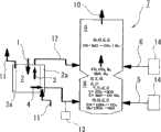
图1是根据本发明的生物质碳化-气化装置的构造示意图;Fig. 1 is the structural representation of biomass carbonization-gasification device according to the present invention;
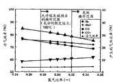
图2是比较计算值和来自油乳胶气化试验结果的试验值(氧气比率为0.40)的图表;Figure 2 is a graph comparing calculated values and experimental values (oxygen ratio 0.40) from oil latex gasification test results;
图3是曲线图,其示出了吹氧型、单级、夹带流动气化器的气化性能的预测(气化剂的输入温度:50℃),表明当氧气比率变化时碳转化效率和气化器出口温度的变化;Fig. 3 is a graph showing the prediction of gasification performance of an oxygen-blown, single-stage, entrained flow gasifier (input temperature of gasification agent: 50°C), showing carbon conversion efficiency and gasification as the ratio of oxygen varies. Changes in the outlet temperature of the carburetor;
图4是曲线图,其示出了吹氧型、单级、夹带流动气化器的气化性能的预测(气化剂的输入温度:50℃),表明当氧气比率变化时产生的气体比率和冷气效率的变化;Figure 4 is a graph showing the prediction of gasification performance of an oxygen-blown, single-stage, entrained flow gasifier (input temperature of gasification agent: 50°C), indicating the gas ratio produced when the ratio of oxygen is varied and changes in cooling efficiency;
图5是曲线图,其示出了空气氧化型、单级、夹带流动气化器的气化性能的预测(空气输入温度:250℃),表明了当氧气比率变化时碳转化效率和气化器出口温度的变化;Figure 5 is a graph showing the prediction of gasification performance of an air oxidation type, single-stage, entrained flow gasifier (air input temperature: 250°C), showing carbon conversion efficiency and gasifier as oxygen ratio varies Changes in outlet temperature;
图6是曲线图,其示出了吹氧、一步加料方法的气化性能的预测,表明了当氧气比率变化时碳转化效率和气化器出口温度的变化;Figure 6 is a graph showing predictions of gasification performance for an oxygen-blown, one-step feed process, showing changes in carbon conversion efficiency and gasifier outlet temperature as oxygen ratios are varied;
图7是曲线图,其示出了吹氧一步加料方法的气化性能的预测,表明了当氧气比率变化时产生的气体比率和冷气效率的变化;Figure 7 is a graph showing the prediction of the gasification performance of the oxygen blowing one-step charging method, showing the changes in the gas ratio and cold gas efficiency produced when the oxygen ratio is changed;
图8是曲线图,其示出了空气氧化、一步加料方法的气化性能的预测,表明了当氧气比率变化时碳转化效率和气化器出口温度的变化;Figure 8 is a graph showing predictions of gasification performance for an air oxidation, one-step feed process, showing changes in carbon conversion efficiency and gasifier outlet temperature as the oxygen ratio is varied;
图9是曲线图,其示出了空气氧化、一步加料方法的气化性能的预测,表明了当氧气比率变化时产生的气体比率和冷气效率的变化;Figure 9 is a graph showing predictions of gasification performance for an air oxidation, one-step feed process, showing changes in gas ratio and cooling efficiency as oxygen ratios are varied;
图10是曲线图,其示出了空气氧化、两步加料方法的气化性能的预测,表明了当氧气比率变化时碳转化效率、燃烧器出口温度、以及气化器出口温度的变化;Figure 10 is a graph showing predictions of gasification performance for an air oxidation, two-step feed process, showing changes in carbon conversion efficiency, burner outlet temperature, and gasifier outlet temperature as oxygen ratios are varied;
图11是曲线图,其示出了空气氧化、两步加料方法的气化性能的预测,表明了当氧气比率变化时产生的气体比率和冷气效率的变化;Figure 11 is a graph showing predictions of gasification performance for an air oxidation, two-step feed process, showing changes in gas ratio and cooling efficiency as oxygen ratios are varied;
图12是曲线图,其示出了空气加入气体转化器的方法的气化性能的预测(燃烧器氧气比率:0.64),表明了当氧气比率变化时碳转化效率、燃烧器出口温度、以及气化器出口温度的变化;Fig. 12 is a graph showing the prediction of the gasification performance of the method of adding air to the gas converter (burner oxygen ratio: 0.64), indicating carbon conversion efficiency, burner outlet temperature, and gas Changes in the outlet temperature of the carburetor;
图13是曲线图,其示出了燃烧器氧气比率(总氧气比率:0.20)对气化性能的影响,表明了当氧气比率变化时碳转化效率、燃烧器出口温度、以及气化器出口温度的变化;13 is a graph showing the effect of burner oxygen ratio (total oxygen ratio: 0.20) on gasification performance, indicating carbon conversion efficiency, burner outlet temperature, and gasifier outlet temperature when the oxygen ratio is varied The change;
图14是曲线图,其示出了燃烧器氧气比率(总氧气比率:0.20)对气化性能的影响,表明了当氧气比率变化时产生的气体比率和冷气效率的变化;14 is a graph showing the influence of burner oxygen ratio (total oxygen ratio: 0.20) on gasification performance, showing changes in gas ratio and cooling efficiency produced when the oxygen ratio is varied;
图15是曲线图,其示出了用于废弃物的两步加料方法的气化性能的预测,表明了当氧气比率变化时碳转化效率、燃烧器出口温度、以及气化器出口温度的变化;Figure 15 is a graph showing predictions of gasification performance for a two-step feed process of waste, showing changes in carbon conversion efficiency, burner outlet temperature, and gasifier outlet temperature as the oxygen ratio is varied ;
图16是曲线图,其示出了用于废弃物的两步加料方法的气化性能的预测,表明了当氧气比率变化时产生的气体比率和冷气效率的变化;Fig. 16 is a graph showing predictions of gasification performance for a two-step charging process of waste, showing changes in gas ratio and cooling efficiency produced as oxygen ratio is varied;
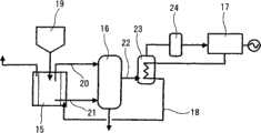
图17是简化示意图,其示出了根据本发明具体实施例的生物质发电装置的构造;以及17 is a simplified schematic diagram showing the construction of a biomass power generation device according to a specific embodiment of the present invention; and
图18是根据本发明的发电装置的立体图,其中多个可顺序地操作的碳化室被设置在单个气化器的周围。Figure 18 is a perspective view of a power plant according to the present invention wherein a plurality of sequentially operable carbonization chambers are arranged around a single gasifier.
具体实施方式Detailed ways
图1所示的本发明的具体实施例是用于高温分解生物质燃料1的生物质碳化-气化装置,该生物燃料为如木材基生物质、包括城市固体废物的废物基生物质、以及这类生物质的混合物。该生物质碳化-气化装置包括:碳化室2,用于接受和加热生物质燃料1以产生碳化材料4;两级气化器7,由用于气化碳化材料4的高温气化部分8和用于转化可燃裂解气3的气体转化器9组成;碳化材料进料器13,用于将碳化材料4送到气化器7的高温气化部分8;裂解气流路12,用于将可燃裂解气3传送到气化器7的气体转化器9;以及气化剂进料装置14,用于将气化剂5送到气化器的高温气化部分8、以及将含氧气化剂6送到气体转化器9。A specific embodiment of the invention shown in Figure 1 is a biomass carbonization-gasification plant for pyrolysis of biomass fuel 1 such as wood-based biomass, waste-based biomass including municipal solid waste, and mixture of such biomass. The biomass carbonization-gasification device includes: a
裂解气3含有在产生碳化材料4的过程中挥发的焦油。这种挥发的焦油将在管道上形成焦油沉积物,除非在气化器出口10的温度保持在预定温度以上。在正常操作中,气化剂5是连续地送到高温气化部分8。然而,只有当在气化器7的出口10的温度下降到预定温度、或当存在温度将下降到预定温度的危险时,气化剂6才被送到气体转化器9。The cracked
生物质燃料1具有较高的含水量以及较差的可粉碎性,其使得粗生物质燃料不适合于用夹带流动气化器进行处理。因此,在图1所示的具体实施例中,采用碳化-气化方法,其中在碳化室2内并在被加入气化器7之前,生物质燃料1被分成挥发性、可燃裂解气3、以及碳化材料4。气体3包含生物质燃料1中的水分以及挥发物,而碳化材料4主要由固定碳和灰分组成。Biomass Fuel 1 had a high water content and poor pulverization, which made the crude biomass fuel unsuitable for processing with an entrained flow gasifier. Therefore, in the specific embodiment shown in Figure 1, a carbonization-gasification method is employed, wherein in the
碳化室2包括用于高温分解生物质燃料1的内部,由夹套2a所包围,在优选大约600℃的温度下气体11被引入其中,用于间接加热生物质燃料1和通过蒸发其水分进行碳化,以及在缺氧条件下热解有机物质,室2的内含物与外部空气隔绝。如以后所描述的,生物质燃料的碳化处理可通过利用来自燃气发动机、燃气轮机、燃料电池、或其他发电装置的废热来进行,其中其他发电装置是利用由气化器产生的气体作为燃料。因此,气体11可以是来自发电装置的废气。The
生物质的水分和可燃裂解气3连续地从碳化室的上部排出,而碳化材料4则从其底部排出。水分和可燃裂解气3经过裂解气流路12被传送到气体转化器9。碳化材料4经过碳化材料进料器13被传送到气化器7的高温气化部分8。碳化材料给料器13可以是任何适当的进料装置,例如,螺旋进料器。Moisture of biomass and combustible cracked
气化器7使从碳化室2送入的碳化材料4、以及含有水分和挥发物的可燃裂解气3进行气化反应,从而产生CO(一氧化碳)和H2(氢气)。The
气化剂进料装置14能够可选择地在气化剂仅送到高温气化部分8的状态和气化剂送到高温气化部分8以及气体转化器9的状态之间进行切换。空气或氧气是通过气化剂进料装置14被送入,从而使燃烧反应发生在高温气化部分8、或发生在高温气化部分8以及气体转化器9。气化剂进料装置14可以由用于吹入空气的装置和适当的管道组成。The gasification
在图1中,为了方便起见两个气化剂进料装置14显示为分开的部件,并且被送到高温气化部分8的气化剂用附图标号5来表示而被送到气体转化器9的气化剂用附图标号6来表示。然而,气化剂进料装置14可以包括具有分支管道和阀门的单个进料器以致气化剂(空气或氧气)可以从其中它仅被送到高温气化部分8的状态转变到其中它被送到高温气化部分8以及气体转化器9的状态。在单个进料器和分支进料管道一起使用的情况下,则可以减小装置的总尺寸并降低其成本。In FIG. 1, the two gasification
被送到碳化室2的生物质燃料1首先在碳化室2内在大约,例如,600℃温度下进行间接热解足够长的时间以被碳化。在碳化生物质燃料1时,其水分和挥发物从碳化室2的上部排出并经过裂解气流路12转移到气体转化器9。高温分解生物质燃料1所需要的时间取决于原料的种类以及其含水量。例如,如果温度调整到大约600℃,则通常用大约30分钟至1小时就可以完成碳化。在令人满意的碳化以后,含有固定碳、灰分、以及相对少量挥发物的碳化材料4从碳化室2排出。因此,在碳化室中的碳化材料4和挥发性气体经过不同的装置被送到气化器7。The biomass fuel 1 sent to the
气化剂5被送到高温气化部分8,其是气化器7的下部,然后利用碳化材料4作为燃料在气化部分进行燃烧和气化。因为来自生物质的水分已被除去并且在该阶段的碳化材料4相对不含水,所以可以产生高温气体,其温度不具有1500℃或更高。此外,在气体转化器9中,其是气化器7的上部,利用高温气体作为热源并通过分解包含在输送自碳化室2的裂解气3中的焦油来进行气体转化。如果可燃裂解气3(其通常在约400℃至600℃的温度范围内)的流率大于装置内碳化材料4的流率,来自高温气化部分8的气体则可能在气体转化器9内经受温度的快速下降。在转化器9中的气体温度不允许下降到低于1100℃的温度,该温度是焦油的分解温度。因此,如果温度下降到1100℃、或通过传感仪器或观察确定存在这种温度下降的急迫危险,则含有空气或氧气的气化剂6被送到气体转化器9,并且部分可燃裂解气3进行燃烧,从而将高温气体的温度提高到至少1100℃的温度,以致可以发生焦油的分解。The
气化器7内的反应可以用如下的简单化学式表示。在高温气化部分8的燃烧反应包括由下述表示的反应:The reaction in the
(1)CO+1/2O2→CO2以及(1)CO+1/2O2 →CO2 and
(2)H2+1/2O2→H2O(2)H2 +1/2O2 →H2 O
而气化反应包括由下述表示的反应:Whereas gasification reactions include reactions represented by:
(3)C+CO2→2CO以及(3) C+CO2 →2CO and
(4)C+H2O→CO+H2(4) C+H2 O→CO+H2
在如上所述的反应以后,CO、CO2、H2、H2O、N2、固定碳、以及灰分从高温气化部分8移到气体转化器9。此后,在气体转化器9中发生由下述表示的转移反应:After the reaction as described above, CO, CO2 , H2 , H2 O, N2 , fixed carbon, and ash move from the high-temperature gasification section 8 to the

由在高温气化部分8进行的燃烧反应和气化反应产生的灰分被转化为熔渣,将其从气化器7的底部除去。Ash generated by the combustion reaction and gasification reaction performed in the high-temperature gasification section 8 is converted into slag, which is removed from the bottom of the
对如上所述的装置可以进行各种变化和改进。例如,如在其后将出现的,多个碳化室可以按时间顺序进行操作,以将碳化材料和可燃裂解气连续送到气化器。此外,在气化器中,高温气化部分和气体转化器可以装备在一个室中,而在其间没有明显分开。例如,可以使用单室,或可以使用在两个部分之间具有限制(restriction)的单室。Various changes and modifications can be made to the apparatus described above. For example, as will appear hereinafter, multiple carbonization chambers may be operated in time sequence to continuously feed carbonized material and combustible cracked gas to the gasifier. Furthermore, in the gasifier, the high-temperature gasification section and the gas reformer may be equipped in one chamber without being significantly separated therebetween. For example, a single chamber may be used, or a single chamber with a restriction between the two parts may be used.
为了检查气化木材基以及废物基生物质(其可以被称为“废弃物”)的过程,本发明者基于燃料性能以及气化反应速率已建立容易预测气化性能的计算技术,并已检查气化各种燃料的过程和操作条件的目标范围,目的是获得高效和稳定的操作。In order to examine the process of gasifying wood-based as well as waste-based biomass (which may be referred to as "waste"), the present inventors have established computational techniques for easily predicting gasification performance based on fuel performance and gasification reaction rates, and have examined Target ranges of process and operating conditions for gasification of various fuels for efficient and stable operation.
利用由电气设备中心研究协会基金(下文仅称作“基金”)开发的将煤气化器以及超重油气化器作为目标的高精度数值分析技术,大量时间用于准备计算点阵以获得气化器7的各种性能的详细结果,如颗粒特征、气体性能、气体温度分布等等,并且需要几个小时来计算一个状态。因此,基于作为目标的燃料种类的性能以及其气化反应速率,基金已建立能够容易预测各种气化性能的计算技术,如碳转化效率、冷气效率、气体温度等等,以使得可以容易地检查气化过程、最佳操作条件等等。就该计算技术来说,没有考虑来自气化器7的炉壁的辐射、颗粒特征、气化器7的形状等等,然而基于气化反应速率以及气相反应速率,可以明了一段时间以后加入气化器7的燃料所发生的反应已进行的程度。Utilizing high-precision numerical analysis techniques targeting coal gasifiers and extra-heavy oil gasifiers developed by the Research Association Fund of the Center for Electrical Equipment (hereinafter referred to simply as "Funds"), a lot of time was spent preparing calculation lattices to obtain
下文将概括地描述如所建立的计算技术。假设关于加入气化器7的燃料,从性能分析值发现的固定碳是焦碳作为气化反应的目的,并且起因于加入气化器7以后的热解,挥发物被立即转化成气体。另外,假设H2O形式的水分被加入气化器7以参与水煤气反应和转移反应。The computational techniques as established will be described in general below. Assuming that regarding the fuel charged to the
假设作为挥发物的C、H、以及O是以气体形式加入,基本上导致基于平衡常数(转移平衡常数Ks)的转移平衡态(CO+H2O=CO2+H2),其中平衡常数示于下面给出的用于Ks的公式中。然而,如果根据燃料中C、H、以及O的比例试图确定CO、CO2、H2、以及H2O的比例,则会发现在大多数情况下O是不够的。因此,当不可能达到转移平衡态时,O与C结合以形成CO,另外,当相对于C来说O不够时,则利用气化剂中的O。假设氢为H2。Assuming that C, H, and O as volatiles are added in gaseous form, it basically leads to a transfer equilibrium state (CO+H2 O=CO2 +H2 ) based on an equilibrium constant (transfer equilibrium constant Ks), where the equilibrium constant is shown in the formula for Ks given below. However, if one tries to determine the proportions of CO,CO2 ,H2 , andH2O from the proportions of C, H, and O in the fuel, it will be found that O is insufficient in most cases. Therefore, O combines with C to form CO when it is not possible to reach a transfer equilibrium state, and additionally, O in the gasification agent is utilized when O is insufficient relative to C. Assume hydrogen isH2 .
最初温度的确定是分别根据燃料和气化剂(空气、氧气)的热焓、以及当转化成CO时挥发物的热值等等。在恒压(Cpi)下各种气体的平均比热是通过利用用于气体温度的六阶多项式近似法来加以计算,如下面所给出的。The initial temperature is determined based on the enthalpy of the fuel and gasification agent (air, oxygen), respectively, and the calorific value of the volatiles when converted to CO, etc. The average specific heat of each gas at constant pressure (Cpi) was calculated by using a sixth order polynomial approximation for the gas temperature, as given below.
用于Ks的公式为:The formula for Ks is:
(6)Ks=([CO2]×[H2])÷([CO]×[H2O])(6) Ks=([CO2 ]×[H2 ])÷([CO]×[H2 O])
=0.0265×exp(3956)÷(T+273)=0.0265×exp(3956)÷(T+273)
其中T为℃。where T is °C.
近似Cpi的多项式是:The polynomial to approximate Cpi is:
(7)Cpi=Ai+BiT+CiT2+DiT3+EiT4+FiT5+GiT6(7) Cpi=Ai+BiT+CiT2 +DiT3 +EiT4 +FiT5 +GiT6
在气化器7内,考虑到由下述公式表示的四种气相反应,但不考虑涉及甲烷、硫、以及其他痕量组分的反应。Within the
(8)CO+1/2O2→CO2(8)CO+1/2O2 →CO2
(9)H2+1/2O2→H2O(9)H2 +1/2O2 →H2 O
(10)CO+H2O→CO2+H2(10)CO+H2 O→CO2 +H2
(11)CO2+H2→CO+H2O(11)CO2 +H2 →CO+H2 O
下表1表示利用相应气相反应的计算获得的反应速率常数Table 1 below shows the reaction rate constants obtained using calculations for the corresponding gas phase reactions
(“c.f.”指上述已被编号的化学式)。("c.f." refers to the numbered formula above).
表1Table 1
关于焦炭的气化反应,考虑到由下面给出的化学式13至15表示的三种反应。对于气化反应速率常数,采用了利用基金的热天平和PDTF(超高温加压燃料反应试验设备)测得的数值。对于焦炭气化反应速率模型,采用了如由阿仑尼乌斯方程式12表示的n阶反应速率公式,其中考虑到温度和压力的影响。表2示出了杉木树皮的数值,作为气化反应速率常数的实例。根据到迄今为止由基金进行的研究,已知气化反应在高温区域变成限速。因此,关于如由化学式14表示的CO2的气化反应,比较了如表2所示的在低温和高温区域的相应的气化反应速率,从而采用更小的数值。另外,根据到迄今为止由基金进行的研究,已知如由化学式15表示的H2O的气化反应比CO2的气化反应更快,以及在这种情况下,假定前者比后者快0.5倍。Regarding the gasification reaction of coke, three reactions represented by
(12)dx/dt=A0Pinexp(-EAi/RT)(12)dx/dt=A0 Pin exp(-EAi /RT)
(13)CO+1/2O2→CO2(13)CO+1/2O2 →CO2
(14)C+CO2→2CO(14)C+CO2 →2CO
(15)C+H2O→CO+H2(15) C+H2 O→CO+H2
表2Table 2
假设气化器7用耐火材料制成,以及利用在气化器7的出口气体温度之间的关系发现了由散逸到气化器7的炉壁所引起的热损失的比率,并且当在基金的新种类液体燃料气化研究加热炉进行油乳胶和渣油的气化试验时发现了下面表达式所示的热损失与热输入量的比率。在温度低于1370℃时使用了来源于油乳胶的气化试验的第一表达式,而温度在以及高于1370℃时则使用了来源于渣油的气化试验的第二表达式。热损失的比率是根据气化器7的出口温度以及那些表达式来确定,另外,通过考虑到气化器7的壁表面积与热输入量的比率进行校正。从而,可以考虑到按比例扩大气化器7的影响。Assuming that the
在温度低于1370℃时:When the temperature is lower than 1370°C:
热损失的比率(%)=3.7666×10⁻³⁴×气化器出口温度(℃)10.836在温度不低于1370℃时:Ratio of heat loss (%) = 3.7666×10⁻³⁴ × gasifier outlet temperature (°C)10.836 When the temperature is not lower than 1370°C:
热损失的比率(%)=-2.97×10⁻⁵×气化器出口温度(℃)2+9.545×10⁻²×气化器出口温度(℃)-71.35Ratio of heat loss (%) = -2.97×10⁻⁵ × gasifier outlet temperature (°C)2 +9.545×10⁻² × gasifier outlet temperature (°C) -71.35
为了检验计算技术的准确性,其与由基金进行的油乳胶的气化试验结果进行了比较。图2示出了在氧气比率(λ)为0.40的情况下在加热炉中的保留时间约5秒钟以后试验值与计算值的比较,此时试验中的气化反应被确定几乎完成。对于反应速率常数,采用了用基金的PDTF测得的数值。To test the accuracy of the calculation technique, it was compared with the results of the gasification test of oil latex conducted by the foundation. Figure 2 shows a comparison of experimental and calculated values after a residence time in the furnace of about 5 seconds at an oxygen ratio (λ) of 0.40, at which point the gasification reaction in the experiment was determined to be almost complete. For the reaction rate constant, the value measured with the PDTF of the fund was used.
在图2中,关于所产生气体的各种气化性能:热值(HHV:更高热值)、碳转化效率(CCE)、以及冷气效率(CGE),研究发现试验值和计算值基本上彼此一致。在各种气体的相应性能之间发现有微小的差异。然而,因为与H2结合的CO的浓度,其是可燃组分,基本上与试验值的浓度一致,所以冷气效率的两种数值基本上彼此一致。这大概是由于假定在燃料的挥发物中的大部分C在加入气化器7以后立即转化为CO,以致CO浓度是在稍微更高的数值加以计算。In Fig. 2, with regard to various gasification properties of the produced gas: heating value (HHV: higher heating value), carbon conversion efficiency (CCE), and cold gas efficiency (CGE), it was found that the experimental value and the calculated value were substantially equivalent to each other unanimous. Minor differences were found between the respective properties of the various gases. However, since the concentration of CO combined with H2 , which is a combustible component, substantially coincides with the concentration of the experimental value, the two numerical values of the cooling efficiency substantially coincide with each other. This is presumably due to the assumption that most of the C in the volatiles of the fuel is converted to CO immediately after feeding into the
已证明,如上所述,CO是在稍微更高的浓度数值加以计算,而其他组分是在稍微更低的数值加以计算,但从预测气化性能的角度看,表示气化效率的碳转化效率、以及冷气效率是在令人满意的数值之内。It has been shown that, as mentioned above, CO is calculated at slightly higher concentration values and other components are calculated at slightly lower values, but from the perspective of predicting gasification performance, carbon conversion, which indicates gasification efficiency Efficiency, and air-conditioning efficiency are within satisfactory values.
利用如已建立的计算技术考察了高效气化作为生物质实例的杉木片的过程。在考察中,特别注意下述几点。The process of efficient gasification of fir chips as an example of biomass was investigated using computational techniques as established. During the inspection, pay special attention to the following points.
在高温气化部分(燃烧器)8出口的气体温度(在两级型气化器的情况下)...从燃烧器壁的耐热性(不高于2000℃)、以及排出熔灰(不低于1600℃)的角度考虑The gas temperature at the outlet of the high-temperature gasification part (burner) 8 (in the case of a two-stage type gasifier) ... from the heat resistance of the burner wall (not higher than 2000 ° C), and the discharge of molten ash ( not lower than 1600°C)
在气化器7出口的气体温度...从焦油产生(不低于1100℃)的角度考虑The gas temperature at the outlet of the
碳转化效率...从高效利用燃料而没有循环利用设备的角度考虑(不小于99.5%:冷气效率不小于75)Carbon conversion efficiency... from the perspective of efficient use of fuel without recycling equipment (not less than 99.5%: air-conditioning efficiency is not less than 75)
表3示出了用于考察的杉木片的特性。因为杉木片的含灰量属于痕量(0.09%),所以假定灰分是作为飞灰在下游排出而不是在气化器7内被渣化和溶化并后来排出。对于气化反应速率常数,利用了如表2所示的杉木树皮的数值。Table 3 shows the characteristics of the fir chips used for the investigation. Since the ash content of the fir chips is trace (0.09%), it is assumed that the ash is discharged downstream as fly ash rather than being slagified and melted in the
表3table 3
(*灰分的假定熔点:1600℃)(*Assumed melting point of ash: 1600°C)
一步夹带流动方法one-step entrained flow method
首先,关于利用简单结构的一步夹带流动方法,分别在吹氧和空气氧化型的情况下考察了最佳操作条件。探索了一种条件,在该条件下在气化器出口的温度不低于1100℃以阻止形成焦油,以及从高气化效率的角度看碳转化效率不小于99.5%。该考察是在下述条件下进行。First, regarding the one-step entrainment flow method utilizing a simple structure, optimal operating conditions were examined in the case of oxygen blowing and air oxidation types, respectively. A condition was sought under which the temperature at the outlet of the gasifier was not lower than 1100° C. to prevent the formation of tar, and the carbon conversion efficiency was not less than 99.5% from the viewpoint of high gasification efficiency. This investigation was carried out under the following conditions.
在气化器内的压力为大气压,以及气化器容量为100t/d。The pressure inside the gasifier was atmospheric pressure, and the capacity of the gasifier was 100 t/d.
当试验的气化反应被确定几乎完成时在气化器内的保留时间为约5秒钟。The residence time in the gasifier when the experimental gasification reaction was determined to be nearly complete was about 5 seconds.
吹氧型一步夹带流动方法Oxygen-blown one-step entrained flow method
图3和图4示出了关于吹氧型的考察结果。因为从氧气产生装置送入的氧气一般浓度为95%,所以假定在气化剂中的氧气浓度为95%,以及5%的剩余部分为氮气。气化剂的输入温度是50℃。根据计算结果预测,在超过0.58的氧气比率范围内碳转化效率不小于99.5%的高效操作是可行的。一般而言,生物质的燃料O含量较高,以致与化石燃料相比其热值较低。因此,计算表明尽管是吹氧型但在超过0.58的高氧气比率下进行操作仍然是需要的以用在气化器7内的保持足够高的温度完成操作。在这种情况下,作为高效操作的另一个指数的冷气效率是58.9%,而产生的气体热值变得低到约1000kcal/m3N。Fig. 3 and Fig. 4 show the results of examination on the oxygen blowing type. Since the oxygen gas fed from the oxygen generator is generally 95% concentrated, it is assumed that the oxygen concentration in the gasification agent is 95%, and the remainder of 5% is nitrogen. The input temperature of the gasifying agent is 50°C. According to the calculation results, it is predicted that a high-efficiency operation with a carbon conversion efficiency of not less than 99.5% in the oxygen ratio range exceeding 0.58 is feasible. In general, biomass has a high fuel O content, resulting in a lower calorific value compared to fossil fuels. Therefore, calculations show that operating at high oxygen ratios in excess of 0.58 despite being of the oxygen blowing type is still required to complete the operation with temperatures within the
空气氧化型一步夹带流动方法Air Oxidation One-Step Entrainment Flow Method
图5表示在空气氧化型的情况下,碳转化效率以及气化器出口处气体温度的计算结果。空气输入温度是250℃。与吹氧型的情况相比,在以相同氧气比率操作时碳转化效率和气体温度均降低,这是因为在以相同氧气比率操作时氮气的量增加到约70倍(在气化剂中氮气的百分数:5%→79%)。因此,发现不可能达到超过99%的碳转化效率,即使用0.80的氧气比率。所以,认为用一步夹带流动方法难以实现空气氧化气化。Fig. 5 shows the calculation results of the carbon conversion efficiency and the gas temperature at the outlet of the gasifier in the case of the air oxidation type. The air input temperature is 250°C. Compared with the case of the oxygen-blown type, both the carbon conversion efficiency and the gas temperature decrease when operating at the same oxygen ratio, because the amount of nitrogen increases to about 70 times when operating at the same oxygen ratio (nitrogen in the gasification agent percentage: 5% → 79%). Therefore, it was found impossible to achieve a carbon conversion efficiency of more than 99%, even with an oxygen ratio of 0.80. Therefore, it is considered difficult to achieve air oxidation gasification with a one-step entrained flow method.
碳化-气化过程carbonization-gasification process
对一种过程进行了考察,其中,为了气化在加入气化器7之前具有较高含水量的生物质,通过在碳化室2内的预处理过程,燃料被分解为主要由固定碳组成的碳化材料4、含有水的挥发性裂解气3、以及燃料中的挥发物。A process was considered in which, in order to gasify biomass with a relatively high water content prior to feeding into the
生物质燃料被送到碳化室2,然后在600℃碳化足够长的时间。为了碳化,可以利用来自气化器7下游过程的高温废气。水分和挥发物在碳化期间从碳化室2的上部排出,而在足够碳化以后,包括固定碳、灰分、以及少量挥发物的碳化材料4从碳化室2排出。因而,在碳化室2中的碳化材料4和裂解气(挥发性气体)3经过不同路径被送到气化器7。需要考察如何向气化器7供给碳化材料4和裂解气3以为气化确定最佳操作条件。Biomass fuel is sent to
在考察最佳过程时,测量了杉木片的挥发特性以确定杉木片中的挥发物进行挥发到什么程度。从而,确定了在600℃下92.6%的挥发物被挥发。因此,假定除固定碳和灰分以外,碳化材料4含有7.4%的挥发物。In investigating the optimum process, the volatility properties of fir chips were measured to determine to what extent the volatiles in the cedar chips were volatilized. Thus, it was confirmed that 92.6% of the volatiles were volatilized at 600°C. Therefore, it is assumed that the
一步加料方法One-step feeding method
首先,对一步加料方法进行考察,其中在碳化室2中分开碳化材料4和挥发性裂解气3仅加入高温气化部分8。在这种情况下,仅对气化器的效率进行考察,而排除碳化室2。如同考察一步夹带流动气化器的情况一样,考察是在下述条件下进行:气化器内的压力为大气压,气化器容量为100t/d,在气化器内的保留时间为5秒钟,以及气化剂中的氧气浓度为95%。图6和图7示出了计算结果。First, the one-step feeding method is considered, in which the carbonized
在这种情况下,因为生物质燃料1在碳化室2进行预处理,所以输入温度提高到600℃,而气化器7内的气体温度由于缺少潜热(因为水分作为蒸汽送入)会提高,以致与一级夹带流动气化器相比在相同氧气比率基础上可以提高气化性能,如碳转化效率、冷气效率等等。(参照图3和图4)。根据计算发现,在氧气比率超过0.27的范围内碳转化效率不小于99.5%,而在此时冷气效率为超过85%的较高值。In this case, since the biomass fuel 1 is pretreated in the
接着,用空气氧化型进行了考察。为了与一级夹带流动气化器的情况进行比较,空气输入温度为250℃。图8和图9示出了计算结果。像在吹氧型的情况下,与一级夹带流动气化器相比,在相同氧气比率下,在气化器7内气体温度的升高伴随有操作中碳转化效率、以及冷气效率的提高,从而甚至用空气氧化型也可以使高效操作成为可能。计算结果表明,在氧气比率不小于0.43的情况下,碳转化效率不小于99.5%的高效操作是可行的。然而,在这种情况下冷气效率为67.8%,而产生的气体热值变成低到约840kcal/m3N。Next, an air oxidation type was examined. For comparison with the case of a one-stage entrained flow gasifier, the air input temperature was 250 °C. Figures 8 and 9 show the calculation results. As in the case of the oxygen-blown type, at the same oxygen ratio, an increase in the gas temperature in the
两步加料方法Two-step feeding method
接着,对两步加料方法进行了考察,其中,在碳化室2中分开的碳化材料4被加入高温气化部分8,而挥发性裂解气3被加入气体转化器(还原器)7。气化剂5仅被加入高温气化部分8,于是由于在碳化材料4和气化剂5之间发生反应,在高温气化部分8形成高温燃烧区,而气体转化反应主要基于转移反应,由于加入气体转化器9的水分和挥发物该转移反应在气体转化器9中进行。图10和图11示出了计算结果。在高温气化部分8内的保留时间被调整到3秒钟,而在气体转化器9内的保留时间被调整到1秒钟。在这种情况下,由于下述理由认为难以实行吹氧操作。首先,在超过3000℃的温度高温气化部分8变成高温燃烧区。其次,相对于从高温气化部分8到气体转化器9的气体流率,从碳化室2送入的挥发性气体的量较大,因而在气体转化器9内发生温度的快速下降,从而使得不可能将气化器出口的温度保持在至少1100℃的水平。因此,仅对空气氧化型的情况进行了考察。Next, a two-step feeding method was examined in which the carbonized
从图10和图11可以预期,在用0.14的超低氧气比率进行操作时,碳转化效率不小于99.5%的高效操作已经是可行的。此时,单独高温气化部分8的氧气比率是0.56。然而,气化器出口的温度约为900℃,在该温度下要担心焦油的形成。同时,在氧气比率为0.20的情况下气化器出口的温度达到1100℃,而此时在高温气化部分8出口的温度计算为2200℃,因此当考虑到炉壁的耐热性时这被认为是不能操作的氧气比率条件。It can be expected from Figure 10 and Figure 11 that when operating with an ultra-low oxygen ratio of 0.14, a high-efficiency operation with a carbon conversion efficiency of not less than 99.5% is already feasible. At this time, the oxygen ratio of the high-temperature gasification section 8 alone was 0.56. However, the temperature at the outlet of the gasifier is about 900°C, at which temperature tar formation is a concern. At the same time, the temperature at the outlet of the gasifier reaches 1100°C at an oxygen ratio of 0.20, and at this time the temperature at the outlet of the high-temperature gasification section 8 is calculated to be 2200°C, so this is considered when considering the heat resistance of the furnace wall Oxygen ratio conditions considered inoperable.
基于计算,氧气比率为0.17时在高温气化部分8出口的温度预期超过2000℃,而在此时,气化器出口的温度是1030℃,其低于1100℃,该温度被认为是稳定操作的指南。那是因为,相对于来自高温气化部分8约2300m3N/h的气体流率,从碳化室2送到气体转化器9的挥发性气体的流率约为5400m3N/h,其几乎相当于前者的2.5倍,以致来自高温气化部分8的气体温度(约2000℃)被迅速下降。因此,当考虑到在高温气化部分8出口的温度以及气化器7出口的温度时,认为难以用这种方法实现稳定的操作。Based on calculations, the temperature at the outlet of the high-temperature gasification section 8 is expected to exceed 2000°C when the oxygen ratio is 0.17, and at this time, the temperature at the outlet of the gasifier is 1030°C, which is lower than 1100°C, which is considered to be a stable operation guide. That is because, relative to the gas flow rate of about 2300 m3 N/h from the high-temperature gasification section 8, the flow rate of the volatile gas sent from the
空气加入气体转化器(还原器)的方法Method of adding air to the gas converter (reducer)
与一步夹带流动方法和一步加料方法相比,用两步加料方法,在以低氧气比率进行操作的情况下可以获得较高的碳转化效率,以致当要求高效操作时两步加料方法被认为是有效的方法。因此,对一种方法进行了考察,其中,空气6被加入气体转化器9,而来自高温气化部分8的可燃气体CO和H2进行燃烧,从而提高在气体转化器9内的气体温度以便提高气化器出口的温度到不低于1100℃同时将在高温气化部分8出口的温度保持在不高于2000℃的水平。Compared with the one-step entrained flow method and the one-step feed method, with the two-step feed method, higher carbon conversion efficiencies can be obtained while operating at low oxygen ratios, so that the two-step feed method is considered the preferred method when efficient operation is required. effective method. Therefore, a method was considered in which the
因为必需用不大于0.16的氧气比率进行操作(燃烧器氧气比率大于0.64)以便防止在高温气化部分8出口的温度变得高于2000℃,如图10所示,所以决定增加总氧气比率,同时燃烧器氧气比率固定在0.64。图12示出了碳转化效率以及气体温度的计算结果。Since it is necessary to operate with an oxygen ratio not greater than 0.16 (the burner oxygen ratio is greater than 0.64) in order to prevent the temperature at the outlet of the high-temperature gasification part 8 from becoming higher than 2000° C., as shown in FIG. 10 , it was decided to increase the total oxygen ratio, At the same time the burner oxygen ratio is fixed at 0.64. Fig. 12 shows the calculation results of carbon conversion efficiency and gas temperature.
计算结果表明,可以将气化器出口的温度提高到至少1100℃的水平同时总氧气比率不小于0.20。当与如图6和图7所示的一步加料方法比较时,显然在更低氧气比率下高效操作是可行的。在这种情况下,可以获得99.8%的碳转化效率以及超过85%的冷气效率。Calculation results show that it is possible to increase the gasifier outlet temperature to a level of at least 1100°C while the total oxygen ratio is not less than 0.20. When compared with the one-step feed method as shown in Figures 6 and 7, it is clear that efficient operation at lower oxygen ratios is feasible. In this case, a carbon conversion efficiency of 99.8% and a cooling efficiency of over 85% can be obtained.
结果是,一种方法适合于杉木片用于碳化-气化过程的情况,其中,来自碳化室2的碳化材料4被加入高温气化部分8,挥发性裂解气3被加入气体转化器9,燃烧器氧气比率被设定较低以便使对高温气化部分8的炉壁的热负载尽可能低,以及另外,空气6被加入气体转化器9以致气化器7出口温度在适当的温度(不低于1100℃)。As a result, a method is suitable for the case where Chinese fir chips are used in the carbonization-gasification process, wherein the carbonized
接着,为了考察燃烧器氧气比率的影响,在总氧气比率保持恒定在0.20的情况下,探寻了气化性能的变化。图13和图14示出了考察的结果。当降低燃烧器氧气比率而没有改变总氧气比率时,观察到:气化器出口温度几乎没有变化,而燃烧器出口温度和碳转化效率则有变得更低的倾向。当考虑到对炉壁的热负载时,燃烧器氧气比率优选尽可能低,并且根据图13和图14可以预期,可以获得就碳转化效率来说的气化性能,其作为高效操作的指数并且不小于99.5%,同时燃烧器氧气比率不小于0.56。Next, in order to investigate the effect of burner oxygen ratio, the change of gasification performance was explored while the total oxygen ratio was kept constant at 0.20. 13 and 14 show the results of the investigation. When reducing the burner oxygen ratio without changing the total oxygen ratio, it was observed that there was little change in the gasifier outlet temperature, while the burner outlet temperature and carbon conversion efficiency tended to become lower. The burner oxygen ratio is preferably as low as possible when considering the heat load on the furnace wall, and as can be expected from Figures 13 and 14, gasification performance in terms of carbon conversion efficiency, which is an index of efficient operation and Not less than 99.5%, while the oxygen ratio of the burner is not less than 0.56.
从上述结果可以预期,一些条件将是使用杉木片时的最佳操作条件,在这些条件下,当燃烧器氧气比率为0.56时在燃烧器内的气体温度可以变得尽可能低,即,氧气比率使高效操作成为可能,以及总氧气比率为0.20。From the above results it can be expected that some conditions will be the optimum operating conditions when using fir chips, under these conditions the gas temperature inside the burner can be made as low as possible when the burner oxygen ratio is 0.56, i.e., oxygen ratio enables efficient operation, as well as a total oxygen ratio of 0.20.
对废弃物气化方法的考察Investigation of Waste Gasification Methods
对利用废弃物而不是杉木片作为燃料的高效废弃物气化方法进行了考察。所用的废弃物是典型的城市固体废物,并且其性能示于表4。因为与迄今考察的杉木片相反,在废弃物中含有百分之几的灰分,所以在假定灰分在气化器7中熔化以便作为炉渣排出的情况下进行考察。因为得不到灰分熔点的测量数据,所以假定熔点为1600℃。An efficient waste gasification method using waste instead of fir chips as fuel was investigated. The waste used is typical municipal solid waste and its properties are shown in Table 4. Since, contrary to the fir chips considered hitherto, the waste contains a few percent ash, the investigation was carried out on the assumption that the ash is melted in the
表4Table 4
*灰分的假定熔点:1600℃*Assumed melting point of ash: 1600°C
作为利用杉木片进行考察的结果,已确定利用碳化-气化过程将碳化材料4加入高温气化部分8以及将挥发性裂解气3加入气体转化器9,高效操作是可行的,因此首先考察将空气作为气化剂5仅加入高温气化部分8的情况。图15和图16示出了计算结果。如同杉木片的情况一样燃料通过量调整到100t/d。然而,关于在碳化室2中的挥发比率,利用当在Okadora有限公司(碳化器的制造商)实际进行碳化时获得的测量值,碳化材料4与裂解气3的重量比例调整到40∶60。As a result of investigations using fir chips, it has been determined that it is feasible to use the carbonization-gasification process to feed the
与杉木片的情况相比较(参照图10和图11),因为在碳化室2中挥发比率下降,所以没有观察到气体转化器9中的气体温度快速下降。此外,因为加入高温气化部分8的碳化材料4的量增加,所以相对于总氧气比率,燃烧器氧气比率变得较低。根据前述可以确定,在高温气化部分8没有形成超高温度区域,并且存在一种氧气比率条件,在该条件下燃烧器温度不高于2000℃,以及在气化器出口的气体温度不低于1100℃,被认为是在稳定操作范围内的温度。基于计算,预计碳转化效率不小于99.5%,同时总氧气比率不小于0.32。在这种情况下,得到冷气效率为超过75%的值,该值是目标值。Compared with the case of fir chips (refer to FIG. 10 and FIG. 11 ), since the volatilization rate decreased in the
此外,由于在总氧气比率不小于0.32的情况下,在高温气化部分8出口的温度不低于1600℃,因此可以认为,在考察所用的废弃物中含有的灰分可以被满意地熔化并且从气化器的高温气化部分8排出。In addition, since the temperature at the outlet of the high-temperature gasification section 8 is not lower than 1600°C under the condition that the total oxygen ratio is not less than 0.32, it can be considered that the ash contained in the waste used in the examination can be satisfactorily melted and removed from the The high temperature gasification part 8 of the gasifier is discharged.
结论in conclusion
基于利用燃料的性能、热天平、以及基金的PDTF发现的气化反应速率,已建立用于气化性能预测的计算技术,在对适用于包括杉木片(具有40%的含水量)的生物质以及废弃物(典型的城市固体废物)的气化过程、以及对高效和稳定操作条件进行考察以后,获得下述结果。Based on gasification reaction rates discovered using fuel properties, thermobalances, and PDTF of the Fund, computational techniques for gasification performance prediction have been established for biomass including fir chips (with 40% moisture content) And after examining the gasification process of waste (typically municipal solid waste), and the efficient and stable operating conditions, the following results were obtained.
在杉木片的情况下,用空气氧化(air-blown)一步夹带流动方法难以实行高效操作,其中燃料是直接加入气化器7。然而,随着采用碳化-气化过程,由此利用碳化室2燃料被分解为碳化材料4以及含有水的裂解气3,并接着分两步加入气化器7,因而高效和稳定的操作是可行的。In the case of fir chips, it is difficult to operate efficiently with an air-blown one-step entrained flow process, where the fuel is fed directly to the
利用碳化-气化过程,在挥发比率较高的情况下,如同杉木片一样,为了将气化器7出口的温度保持在足以阻止焦油形成的温度(1100℃),必需将空气或氧气6加入气体转化器9。Using the carbonization-gasification process, in the case of a high volatilization ratio, like fir chips, in order to keep the temperature at the outlet of the
由于废弃物含有许多灰分,因此从环境保护的角度考虑需要熔化灰分以作为炉渣排出。由于在废弃物中的低挥发比率,通过采用将空气仅加入两级气化器的高温气化部分8的方法,高效和熔灰分排出操作是可行的。Since the waste contains a lot of ash, it is necessary to melt the ash to be discharged as slag from the viewpoint of environmental protection. Due to the low volatilization ratio in the waste, high efficiency and molten ash discharge operation is possible by adopting the method of feeding air only into the high temperature gasification part 8 of the two-stage gasifier.
图17和图18示出了本发明的另一个方面,其中动力产生自生物质。生物质发电装置包括:碳化器15,其不仅能够高温分解和碳化木材基生物质而且能够高温分解和碳化废物基生物质,如城市固体废物等等;气化器16,用于燃烧和气化在碳化器15中产生的碳;以及发电机组17,其可用在气化器16中产生的气体作为能源进行运转,用于产生电力。发电机组放出废热,如将看到的,其用于碳化器的操作。Figures 17 and 18 illustrate another aspect of the invention in which power is generated from biomass. The biomass power generation device includes: a
碳化器15可以和图1中的碳化器2相同,其具有用于接受生物质的内室,并由用于接受热气作为热源的夹套所包围,以在内室中高温分解和碳化生物质。碳化器15的夹套经过废气进料路径18连接于发电机组17,用于直接接受由发电机组17放出的废气,以致装置通过有效利用废气的热量来达到较高的热效率。碳化室15的夹套为垂直环状筒体的形状,而高温(例如600℃)废气被引入夹套,以通过外部加热进行碳化。碳化器的筒形内部可以装有转子叶片(未示出),而通过旋转转子叶片燃料可以压住碳化室的内壁,从而增强热传导以及改善碳化效率。适用于实施本具体实施例的碳化室15可以是,例如,由Okadora有限公司制造的超高速碳化器。然而,各种形式的碳化室是适合的。例如,可以使用外部加热的筒形回转窑。The
利用具有上述结构的碳化室15,可以产生优质碳,即,具有很少水分但热值较高的碳化燃料。在释放热量给生物质燃料以后,废气通过烟囟被放出。也就是说,碳化室15经过废气进料路径18利用来自发电机组17的装置废热作为热源,用于间接高温分解生物质燃料。热解所需的时间随作为原料供给的生物质的种类以及生物质中的含水量而变化。然而,在大多数情况下,当使用约600℃的废气时,可以在约30分钟至1小时内完成碳化。With the
可以为碳化提供多个室,并按时间顺序轮流地操作,从而连续地将碳和裂解气送到气化器16。就蒸发的量而论,在碳化室内的碳化过程必然伴随某些变化。然而,如果碳化器的多个单元轮流地操作,则可以减轻这种变化的影响。Multiple chambers may be provided for the carbonization and operated in turn in time sequence so that the carbon and cracked gas are continuously fed to the
原料储槽19连接于碳化器,用于将作为燃料的生物质加入碳化器15。由木材基生物质组成的原料、或由木材基生物质以及废物基生物质的混合物组成的原料可以首先送到原料储槽19,然后顺序地供给到多室碳化器的碳化室。The raw
气化器16是一种加热炉,该加热炉用于燃烧和气化在碳化室15产生的碳,转化在碳化期间挥发的含有焦油的可燃裂解气,以及将燃料中的灰分转化成熔渣。该气化器可以作为单个加热炉安装在生物质发电装置中。然而,在大规模生物质发电装置的情况下,例如,容量超过例如50兆瓦的工厂,多个气化器单元可以通过燃气轮机相互连接,而单元的数目及其结构取决于装置的型式和规模。The
在气化器16出口的温度取决于碳的热值和量、以及输入空气的量。例如,在加热炉下部的温度在某些情况下可以达到高达1500℃的水平,这是因为与碳的热值和量相适应的相对大量的空气被引入气化器,因为在至少约600℃的温度下碳和裂解气被加入气化器16,因为在进入气化器之前生物质燃料中的水分在600℃下被转变成蒸汽,以及因为优质碳(即,热值较高且含有很少水的碳)用作燃料。因而,利用根据本发明的生物质发电装置,其中气化器16的加热炉内温度达到1100℃(其是焦油的分解温度)、或高于该温度,在碳化室15中碳化时已挥发的含有焦油的裂解气在气化器16的上部(气体转化器)进行转化。因为包含在裂解气中的焦油是在高温条件下进行分解,其中高温条件是利用在加热炉下部(气化/熔化部分)的高热而产生,所以可以避免焦油粘附于管道等等。因而,根据本发明的气化器16在加热炉下部实现高温燃烧,从而熔化燃料中的灰分,以及同时利用在其下部产生的热量在加热炉的上部实现裂解气的转化,从而用单个单元完成两种功能。从可靠地阻止焦油形成的角度考虑1100℃是优选的温度,但甚至在低于1100℃的温度也可以阻止焦油的形成。然而,与利用,例如,不能在这种温度区操作的流化床加热炉、以及固定加热炉的传统装置相反,根据本具体实施例的生物质发电装置具有下述特点:由于气化器的特定结构,加热炉内温度可以达到1100℃、或更高。The temperature at the outlet of the
此外,利用气化器16,因为达到较高的加热炉内温度,所以不仅可以分解裂解气中的焦油,而且甚至焦油中的灰分可以在高温下熔化并转化成炉渣。如果废物基生物质与木材基生物质混合以进行燃烧,这将导致灰分很可能含有重金属。然而,如果灰分可以熔化并转化成炉渣,则可以在一定条件下排出灰分,其中没有洗脱重金属的危险、或如此小的危险以致无需采取特定的防范措施来阻止冼脱灰分的组分。In addition, with the
焦油-裂解气进料路径20以及碳进料路径21是设置在气化器16和碳化室15之间。前者,即,焦油-裂解气进料路径20是将在碳化室15产生的焦油和裂解气送到气化器16的流路,而后者,即,碳进料路径21是将在相同碳化室15产生的碳送到气化器16的流路。例如,就本具体实施例来说,利用例如螺旋输送机的碳进料路径21连接于碳化室15的下部,从而利用碳作为燃料进行燃烧和气化,以致尤其在加热炉下部的温度升高到较高温度,于是通过将空气送到加热炉下部可以产生不低于1100℃的高温气体、或在某些情况下不低于1500℃。同时,在加热炉上部进行气体转化,以及利用高温气体作为热源,在碳化器15中部分高温分解的焦油在加热炉上部被分解。在气化器16中产生的气体作为热源在其后的阶段经过所产生气体的进料路径22被输送到发电机组17。The tar-cracked
在这种情况下,虽然产生的气体可以经过所产生气体的进料路径22被直接输送到发电机组17,但优选在产生的气体和来自发电机组17的废气之间进行热交换。这可以引起来自所产生气体的热量传递到来自发电机组17的废气,以致送到碳化器15的用作热源的废气可以具有更高的温度,从而可以获得更高的热效率。例如,在示于图17的具体实施例中,所产生气体的换热器23以这样的方式进行安装以致引起所产生气体的进料路径22在大约中点与废气进料路径18、或其附近交叉。在气化器16中产生的气体在换热器23中损失其热量,从而被冷却,并在包含在气体中的粉尘、硫、以及其他污染物质用气体净化器24除去后,被输送到发电机组17,其中气体净化器被安装在换热器23和发电机组17之间。In this case, heat exchange is preferably performed between the generated gas and the exhaust gas from the generator set 17 , although the generated gas may be sent directly to the generator set 17 via the generated
发电机组17是用在气化器16中产生的气体进行操作,用于产生电力。它还经过废气进料路径18将废热传送到碳化器。在这种情况下,废气进料路径18可以直接连接于碳化室15。然而,在所说明的具体实施例中,所产生气体的换热器23安装在沿废气进料路径18的中点以便能够在气化器16中产生的气体和来自发电机组17的废气之间进行热交换。因此,可以回收来自发电机组17的废气的热量以及来自气化器16所产生气体的热量并用于碳化器,从而使得整个装置可以达到更高的热效率。可以采用其他型式,如在与废气热交换后通过蒸汽介质利用废热的型式。The generator set 17 is operated on the gas produced in the
在图18所示的具体实施例中,将多个碳化室25设置在单个气化器26周围,其具有高温气化部分27和气体转化器28。这些碳化室轮流地操作以将碳和裂解气连续地供给气化器26。也就是说,碳化发生在第一个碳化室25中,以及裂解气被从第一碳化室送到气体转化器28同时碳被从第二碳化室送到气化器的高温气化部分27。其后,第二碳化室再装填生物质,并且互换碳化室的功能,以致从第一室供给碳而碳化发生在第二室,以及将裂解气从第二室送到气体转化器。当然,两个以上的碳化室可以与单个气化器相联,并按适当的时间顺序进行操作。In the specific embodiment shown in FIG. 18 , a plurality of
如上文所述,通过将利用装置废热的碳化过程和气化过程结合起来,生物质发电装置可以实现高效发电而不使用补充燃料。我们已估计,用根据本发明的生物质发电装置,可以获得34%的热效率,其超过30%,而30%是“生物质Nippon(日本)综合战略”的热效率的目标值(在100t/d规模的情况下),如下所述。更具体而言,利用根据图17的具体实施例的生物质发电装置,通过系统化碳化室15以及发电机组17,已可以有效利用伴随发电的废气的废热,所以可以比在传统的情况下获得更高的热效率、以及不仅高温分解和碳化木材基生物质而且高温分解和碳化废物基生物质,如城市固体废物等等,而没有使用补充燃料。换而言之,因为木材基生物质的含水量高于废物基生物质,所以难以将处于混合状态的两种生物质转化成具有稳定性能的燃料。然而,在根据本具体实施例的生物质发电装置的情况下,利用能够有效地利用废热并装备在装置的前段的碳化室15,可以在碳化过程中干燥处于混合状态的两种生物质(在某种意义上为非均质燃料)并在其后转化成具有稳定性能的燃料,其含有给定含水量(例如,约1%)并如果需要的话可以粉化。此外,与目前可获得的1兆瓦规模的发电装置相反,其基于,例如,在其锅炉中的燃烧,其中发电效率至多大约仅为10%,利用根据本发明的生物质发电装置,可以获得30%或更好的发电效率。As mentioned above, by combining the carbonization process and the gasification process utilizing waste heat from the plant, the biomass power plant can achieve high-efficiency power generation without using supplementary fuel. We have estimated that with the biomass power generation device according to the present invention, a thermal efficiency of 34% can be obtained, which exceeds 30%, and 30% is the target value of thermal efficiency of "biomass Nippon (Japan) comprehensive strategy" (at 100t/d scale), as described below. More specifically, using the biomass power generation device according to the specific embodiment of Fig. 17, through the systematization of the
“生物质Nippon综合战略”是促进利用生物质的战略,其由日本农业、林业、以及渔业部,经济、贸易、以及工业部,土地、基本设施、以及运输部,环境部,以及教育部共同安排,并在2002年12月的内阁会议上决定。在日期为2002年12月12日的“生物质Nippon综合战略”中,例如,在第12页,有一种描述,大意是说,与直接燃烧和气化工厂的技术等等有关,用于将含水量较低的生物质转化成能量,有待开发一种技术,由此在工厂(假定基于几个市区规模)可以实现大约20%(在电力方面)、或大约80%(在热量方面)的能量转化效率,其中生物质通过量大约为20t/d,或在工厂(假定在市区)可以实现大约30%(在电力方面)的能量转化效率,其中生物质通过量大约为100t/d,只要建立起在广泛区域适合于收集生物质的环境(在这里,能量转化效率指生物质燃料的化学能(热值)转化成电力的比率)。根据本具体实施例的生物质发电装置正好跟促进利用生物质一致,其是“综合战略”的目的。"Biomass Nippon Comprehensive Strategy" is a strategy to promote the use of biomass, which is jointly organized by the Ministry of Agriculture, Forestry, and Fisheries, the Ministry of Economy, Trade, and Industry, the Ministry of Land, Infrastructure, and Transport, the Ministry of Environment, and the Ministry of Education. Arranged and decided at the December 2002 Cabinet meeting. In "Biomass Nippon Integrated Strategy" dated December 12, 2002, for example, on
根据本发明的生物质发电装置比传统发电机组具有几个优点。第一,因为不仅木材基生物质而且废物基生物质如城市固体废物、废塑料等等,都可以加以利用,所以可获量受季节变化影响的木材基生物质燃料可以通过废物基生物质被补充,因此可以获得稳定的输出功率。第二,包括废弃物的废物基生物质通常以相对较高的成本进行处理。然而,如果这样的废弃物作为用于发电的燃料的一部分加以收集,则可以改善木材基生物质收集的经济效果。第三,由本发明提供的可获得燃料量的增加使得可以增加发电设备的规模,使得高效发电成为可能。第四,因为不产生二氧芑、以及通过转化成熔渣灰分变得无害,所以发电装置可用作一般废物以及工业废料的处理设备,并有助于环境保护。第五,通过碳化过程和气化过程的结合,粗生物质的体积被减少到其最初体积的约1/5至1/7,以致可以使用紧凑型气化器。最后,该装置可以由没有专门技能的工人进行操作。The biomass power plant according to the present invention has several advantages over conventional generator sets. First, since not only wood-based biomass but also waste-based biomass such as municipal solid waste, waste plastics, etc. supplement, so a stable output power can be obtained. Second, waste-based biomass, including waste, is typically processed at relatively high cost. However, the economics of wood-based biomass collection could be improved if such waste was collected as part of the fuel used to generate electricity. Thirdly, the increase in the amount of fuel available provided by the present invention makes it possible to increase the size of power generation facilities, making efficient power generation possible. Fourth, since dioxins are not produced, and become harmless by conversion into slag ash, the power generation device can be used as a treatment facility for general waste as well as industrial waste, and contributes to environmental protection. Fifth, through the combination of carbonization process and gasification process, the volume of crude biomass is reduced to about 1/5 to 1/7 of its original volume, so that a compact gasifier can be used. Finally, the device can be operated by workers without specialized skills.
以上所述仅为本发明的优选实施例而已,并不用于限制本发明,对于本领域的技术人员来说,本发明可以有各种更改和变化。凡在本发明的精神和原则之内,所作的任何修改、等同替换、改进等,均应包含在本发明的保护范围之内。例如,就上述具体实施例来说,城市固体废物、废塑料等等是列举为废物基生物质的特定实例。然而,那些材料仅通过举例来列举,而在根据本发明的生物质发电装置的情况下,可以使用其他生物质,包括较高含水量的生物质,如农业资源、森林资源、畜牧业资源、以及水生资源、这些资源的废弃物、建筑材料废物、食品废物、污泥等等,而不管它是木材基生物质还是废物基生物质。The above descriptions are only preferred embodiments of the present invention, and are not intended to limit the present invention. For those skilled in the art, the present invention may have various modifications and changes. Any modifications, equivalent replacements, improvements, etc. made within the spirit and principles of the present invention shall be included within the protection scope of the present invention. For example, with respect to the above specific embodiments, municipal solid waste, waste plastics, etc. are cited as specific examples of waste-based biomass. However, those materials are listed by way of example only, and in the case of the biomass power generation device according to the present invention, other biomass, including biomass with a higher water content, such as agricultural resources, forest resources, animal husbandry resources, As well as aquatic resources, waste from these resources, construction material waste, food waste, sludge, etc., whether it is wood-based biomass or waste-based biomass.
Claims (13)
Translated fromChineseApplications Claiming Priority (4)
| Application Number | Priority Date | Filing Date | Title |
|---|---|---|---|
| JP85108/2004 | 2004-03-23 | ||
| JP2004085108AJP4276973B2 (en) | 2004-03-23 | 2004-03-23 | Biomass power generation system |
| JP180122/2004 | 2004-06-17 | ||
| JP2004180122AJP2006002042A (en) | 2004-06-17 | 2004-06-17 | Biomass carbonization / gasification system and carbonization / gasification method |
Related Parent Applications (1)
| Application Number | Title | Priority Date | Filing Date |
|---|---|---|---|
| CN2005100568294ADivisionCN1673317B (en) | 2004-03-23 | 2005-03-22 | Biomass carbonization and gasification and power generation device |
Publications (2)
| Publication Number | Publication Date |
|---|---|
| CN101614154Atrue CN101614154A (en) | 2009-12-30 |
| CN101614154B CN101614154B (en) | 2012-01-25 |
Family
ID=35172551
Family Applications (1)
| Application Number | Title | Priority Date | Filing Date |
|---|---|---|---|
| CN2009101502273AExpired - Fee RelatedCN101614154B (en) | 2004-03-23 | 2005-03-22 | Biomass power generation system |
Country Status (2)
| Country | Link |
|---|---|
| JP (1) | JP4276973B2 (en) |
| CN (1) | CN101614154B (en) |
Cited By (6)
| Publication number | Priority date | Publication date | Assignee | Title |
|---|---|---|---|---|
| CN101962557A (en)* | 2010-09-17 | 2011-02-02 | 昆明理工大学 | Combined process for preparing biomass carbon reductant and producing industrial silicon |
| CN102116193A (en)* | 2011-01-11 | 2011-07-06 | 安徽友勇生物科技有限公司 | Rice hull generating equipment |
| WO2012056332A2 (en) | 2010-10-25 | 2012-05-03 | New Energy Group, Uab | Integrated system, composed of a thermal power plant, electric power plant, and modules of pyrolisis-based production line, improvement of this system's modules, and method of usage of such system |
| CN104595060A (en)* | 2015-01-08 | 2015-05-06 | 赵卫强 | Gas generator, gas supply system and vehicle power system |
| CN105602630A (en)* | 2015-10-19 | 2016-05-25 | 浙江大学 | Technology for catalysis and quality improvement by using waste gasified gases |
| CN110616089A (en)* | 2019-09-26 | 2019-12-27 | 同济大学 | Gasification device for producing synthesis gas from high-moisture organic material |
Families Citing this family (22)
| Publication number | Priority date | Publication date | Assignee | Title |
|---|---|---|---|---|
| JP2006128006A (en)* | 2004-10-29 | 2006-05-18 | Central Res Inst Of Electric Power Ind | Biomass gasification high-temperature fuel cell power generation system for biomass |
| JP4682027B2 (en)* | 2005-11-25 | 2011-05-11 | 株式会社キンセイ産業 | Fuel gas generator |
| JP4790412B2 (en)* | 2005-12-28 | 2011-10-12 | 中外炉工業株式会社 | Biomass gasifier |
| JP4644831B2 (en)* | 2006-01-31 | 2011-03-09 | 独立行政法人産業技術総合研究所 | Liquid fuel production equipment from biomass |
| JP4696969B2 (en)* | 2006-02-28 | 2011-06-08 | 日立造船株式会社 | Gasifier |
| JP5419250B2 (en)* | 2007-01-19 | 2014-02-19 | 月島機械株式会社 | Gasification method and gasification equipment for organic matter |
| JP4711980B2 (en)* | 2007-01-31 | 2011-06-29 | 独立行政法人産業技術総合研究所 | Liquid fuel production equipment from biomass |
| JP5036037B2 (en)* | 2007-03-29 | 2012-09-26 | 国立大学法人広島大学 | Biomass gasification power generation system |
| JP5372343B2 (en)* | 2007-06-04 | 2013-12-18 | 三井造船株式会社 | Tar reforming reactor |
| JP5460970B2 (en)* | 2008-03-28 | 2014-04-02 | 三井造船株式会社 | Woody biomass gas reforming system |
| WO2010024414A1 (en)* | 2008-08-30 | 2010-03-04 | 有限会社プラス化建・工法研究所 | Device for fixing biomass-based solar heat and carbon dioxide gas, and house equipped with same fixing device |
| JP5384087B2 (en)* | 2008-11-26 | 2014-01-08 | 三井造船株式会社 | Woody biomass gas reforming system |
| JP5432554B2 (en)* | 2009-03-25 | 2014-03-05 | 一般財団法人電力中央研究所 | Gasification system |
| CN101709228B (en)* | 2009-11-26 | 2013-04-17 | 中节环(北京)能源技术有限公司 | Biomass three-section type entrained flow bed gasification technology with function of waste heat utilization |
| CN101906326B (en) | 2010-07-20 | 2013-03-13 | 武汉凯迪控股投资有限公司 | Biomass double furnace cracking and gasification technology and device |
| CN101906325B (en)* | 2010-07-20 | 2013-09-04 | 阳光凯迪新能源集团有限公司 | Process and apparatus thereof for low-temperature cracking and high-temperature gasification of biomass |
| CN103119135B (en)* | 2010-07-27 | 2017-06-30 | 科廷科技大学 | Method and gasification system for gasifying carbonaceous material |
| JP5286529B2 (en)* | 2011-07-05 | 2013-09-11 | 国立大学法人 東京大学 | Power generation apparatus and power generation method |
| JP5917938B2 (en)* | 2012-02-20 | 2016-05-18 | 国立大学法人東北大学 | Power generation system operation method |
| JP2013241487A (en)* | 2012-05-17 | 2013-12-05 | Central Research Institute Of Electric Power Industry | System for carbonizing and gasifying biomass |
| JP6066809B2 (en) | 2013-04-10 | 2017-01-25 | 三菱重工環境・化学エンジニアリング株式会社 | Biomass pyrolysis device and power generation system |
| WO2020234978A1 (en)* | 2019-05-20 | 2020-11-26 | 株式会社 ユーリカ エンジニアリング | System for co-production of co2-free power and hydrogen from biomass |
Family Cites Families (1)
| Publication number | Priority date | Publication date | Assignee | Title |
|---|---|---|---|---|
| JPH10185138A (en)* | 1996-12-20 | 1998-07-14 | Masao Kanai | Carbonizing device |
- 2004
- 2004-03-23JPJP2004085108Apatent/JP4276973B2/ennot_activeExpired - Fee Related
- 2005
- 2005-03-22CNCN2009101502273Apatent/CN101614154B/ennot_activeExpired - Fee Related
Cited By (9)
| Publication number | Priority date | Publication date | Assignee | Title |
|---|---|---|---|---|
| CN101962557A (en)* | 2010-09-17 | 2011-02-02 | 昆明理工大学 | Combined process for preparing biomass carbon reductant and producing industrial silicon |
| WO2012056332A2 (en) | 2010-10-25 | 2012-05-03 | New Energy Group, Uab | Integrated system, composed of a thermal power plant, electric power plant, and modules of pyrolisis-based production line, improvement of this system's modules, and method of usage of such system |
| LT5861B (en) | 2010-10-25 | 2012-08-27 | Uab "New Energy Group" | Integrated system, composed of a thermal power plant, electric power plant, and modules of pyrolisis - based production line, improvement of this system's modules, and method of usage of such system |
| CN102116193A (en)* | 2011-01-11 | 2011-07-06 | 安徽友勇生物科技有限公司 | Rice hull generating equipment |
| CN104595060A (en)* | 2015-01-08 | 2015-05-06 | 赵卫强 | Gas generator, gas supply system and vehicle power system |
| CN104595060B (en)* | 2015-01-08 | 2017-12-12 | 南京众慧网络科技有限公司 | Gas generator, gas supply system and vehicle power system |
| CN105602630A (en)* | 2015-10-19 | 2016-05-25 | 浙江大学 | Technology for catalysis and quality improvement by using waste gasified gases |
| CN110616089A (en)* | 2019-09-26 | 2019-12-27 | 同济大学 | Gasification device for producing synthesis gas from high-moisture organic material |
| CN110616089B (en)* | 2019-09-26 | 2021-05-11 | 同济大学 | A gasification device for producing synthesis gas from organic materials with high moisture content |
Also Published As
| Publication number | Publication date |
|---|---|
| JP4276973B2 (en) | 2009-06-10 |
| JP2005272530A (en) | 2005-10-06 |
| CN101614154B (en) | 2012-01-25 |
Similar Documents
| Publication | Publication Date | Title |
|---|---|---|
| CN1673317B (en) | Biomass carbonization and gasification and power generation device | |
| CN101614154A (en) | Carbonization and gasification of biomass and power plant | |
| Seo et al. | Gasification of municipal solid waste | |
| Asadullah | Barriers of commercial power generation using biomass gasification gas: A review | |
| US8858661B2 (en) | Method and apparatus of gasification under the integrated pyrolysis reformer system (IPRS) | |
| Klinghoffer et al. | Gasification and pyrolysis of municipal solid waste (MSW) | |
| KR100993908B1 (en) | Energy fueling method of flammable waste and gasifier of flammable waste | |
| JP4547244B2 (en) | Organic gasifier | |
| JP2008260832A (en) | Method for waste regeneration treatment and system for waste regeneration treatment | |
| Mallick et al. | Emerging commercial opportunities for conversion of waste to energy: Aspect of gasification technology | |
| Arjharn et al. | Evaluation of an energy production system from sewage sludge using a pilot-scale downdraft gasifier | |
| Konda et al. | Syngas production from gasification of oil palm fronds with an updraft gasifier | |
| Vikraman et al. | Air flowrate and particle size effect on gasification of arecanut husk with preheated air through waste heat recovery from syngas | |
| KR101507956B1 (en) | Steam supply and power generation energy system using organic waste and method thereof | |
| KR101097443B1 (en) | Method of transforming combustible wastes into energy fuel and Gasification system of combustible wastes | |
| JP2006002042A (en) | Biomass carbonization / gasification system and carbonization / gasification method | |
| JP5503485B2 (en) | Biomass carbonization / gasification system and carbonization / gasification method | |
| JP2017014474A (en) | Biomass feedstock gasifier of continuous thermochemistry type | |
| JP5945929B2 (en) | Waste gasification and melting equipment | |
| WO2005080874A1 (en) | Waste fusion treatment method utilizing powdery biomass | |
| JP7291677B2 (en) | Water gas generation system, biomass power generation system and biomass hydrogen supply system | |
| JP2006335937A (en) | Organic compound heating equipment | |
| EA038741B1 (en) | Method and combined solid fuel gasifier for gasification of solid fuel | |
| JP2008036457A (en) | Organic matter processing equipment | |
| JP2008036458A (en) | Organic matter processing equipment |
Legal Events
| Date | Code | Title | Description |
|---|---|---|---|
| C06 | Publication | ||
| PB01 | Publication | ||
| C10 | Entry into substantive examination | ||
| SE01 | Entry into force of request for substantive examination | ||
| C14 | Grant of patent or utility model | ||
| GR01 | Patent grant | ||
| C17 | Cessation of patent right | ||
| CF01 | Termination of patent right due to non-payment of annual fee | Granted publication date:20120125 Termination date:20140322 |