CN101612936B - Regulation and control of output torque of transmission in hybrid power electrical vehicle - Google Patents
Regulation and control of output torque of transmission in hybrid power electrical vehicleDownload PDFInfo
- Publication number
- CN101612936B CN101612936BCN200910149033.1ACN200910149033ACN101612936BCN 101612936 BCN101612936 BCN 101612936BCN 200910149033 ACN200910149033 ACN 200910149033ACN 101612936 BCN101612936 BCN 101612936B
- Authority
- CN
- China
- Prior art keywords
- described motor
- motor
- charge
- less
- torque
- Prior art date
- Legal status (The legal status is an assumption and is not a legal conclusion. Google has not performed a legal analysis and makes no representation as to the accuracy of the status listed.)
- Expired - Fee Related
Links
Images


Classifications
- B—PERFORMING OPERATIONS; TRANSPORTING
- B60—VEHICLES IN GENERAL
- B60W—CONJOINT CONTROL OF VEHICLE SUB-UNITS OF DIFFERENT TYPE OR DIFFERENT FUNCTION; CONTROL SYSTEMS SPECIALLY ADAPTED FOR HYBRID VEHICLES; ROAD VEHICLE DRIVE CONTROL SYSTEMS FOR PURPOSES NOT RELATED TO THE CONTROL OF A PARTICULAR SUB-UNIT
- B60W20/00—Control systems specially adapted for hybrid vehicles
- B60W20/10—Controlling the power contribution of each of the prime movers to meet required power demand
- B60W20/13—Controlling the power contribution of each of the prime movers to meet required power demand in order to stay within battery power input or output limits; in order to prevent overcharging or battery depletion
- B—PERFORMING OPERATIONS; TRANSPORTING
- B60—VEHICLES IN GENERAL
- B60K—ARRANGEMENT OR MOUNTING OF PROPULSION UNITS OR OF TRANSMISSIONS IN VEHICLES; ARRANGEMENT OR MOUNTING OF PLURAL DIVERSE PRIME-MOVERS IN VEHICLES; AUXILIARY DRIVES FOR VEHICLES; INSTRUMENTATION OR DASHBOARDS FOR VEHICLES; ARRANGEMENTS IN CONNECTION WITH COOLING, AIR INTAKE, GAS EXHAUST OR FUEL SUPPLY OF PROPULSION UNITS IN VEHICLES
- B60K6/00—Arrangement or mounting of plural diverse prime-movers for mutual or common propulsion, e.g. hybrid propulsion systems comprising electric motors and internal combustion engines
- B60K6/20—Arrangement or mounting of plural diverse prime-movers for mutual or common propulsion, e.g. hybrid propulsion systems comprising electric motors and internal combustion engines the prime-movers consisting of electric motors and internal combustion engines, e.g. HEVs
- B60K6/22—Arrangement or mounting of plural diverse prime-movers for mutual or common propulsion, e.g. hybrid propulsion systems comprising electric motors and internal combustion engines the prime-movers consisting of electric motors and internal combustion engines, e.g. HEVs characterised by apparatus, components or means specially adapted for HEVs
- B60K6/36—Arrangement or mounting of plural diverse prime-movers for mutual or common propulsion, e.g. hybrid propulsion systems comprising electric motors and internal combustion engines the prime-movers consisting of electric motors and internal combustion engines, e.g. HEVs characterised by apparatus, components or means specially adapted for HEVs characterised by the transmission gearings
- B60K6/365—Arrangement or mounting of plural diverse prime-movers for mutual or common propulsion, e.g. hybrid propulsion systems comprising electric motors and internal combustion engines the prime-movers consisting of electric motors and internal combustion engines, e.g. HEVs characterised by apparatus, components or means specially adapted for HEVs characterised by the transmission gearings with the gears having orbital motion
- B—PERFORMING OPERATIONS; TRANSPORTING
- B60—VEHICLES IN GENERAL
- B60K—ARRANGEMENT OR MOUNTING OF PROPULSION UNITS OR OF TRANSMISSIONS IN VEHICLES; ARRANGEMENT OR MOUNTING OF PLURAL DIVERSE PRIME-MOVERS IN VEHICLES; AUXILIARY DRIVES FOR VEHICLES; INSTRUMENTATION OR DASHBOARDS FOR VEHICLES; ARRANGEMENTS IN CONNECTION WITH COOLING, AIR INTAKE, GAS EXHAUST OR FUEL SUPPLY OF PROPULSION UNITS IN VEHICLES
- B60K6/00—Arrangement or mounting of plural diverse prime-movers for mutual or common propulsion, e.g. hybrid propulsion systems comprising electric motors and internal combustion engines
- B60K6/20—Arrangement or mounting of plural diverse prime-movers for mutual or common propulsion, e.g. hybrid propulsion systems comprising electric motors and internal combustion engines the prime-movers consisting of electric motors and internal combustion engines, e.g. HEVs
- B60K6/42—Arrangement or mounting of plural diverse prime-movers for mutual or common propulsion, e.g. hybrid propulsion systems comprising electric motors and internal combustion engines the prime-movers consisting of electric motors and internal combustion engines, e.g. HEVs characterised by the architecture of the hybrid electric vehicle
- B60K6/48—Parallel type
- B60K6/485—Motor-assist type
- B—PERFORMING OPERATIONS; TRANSPORTING
- B60—VEHICLES IN GENERAL
- B60K—ARRANGEMENT OR MOUNTING OF PROPULSION UNITS OR OF TRANSMISSIONS IN VEHICLES; ARRANGEMENT OR MOUNTING OF PLURAL DIVERSE PRIME-MOVERS IN VEHICLES; AUXILIARY DRIVES FOR VEHICLES; INSTRUMENTATION OR DASHBOARDS FOR VEHICLES; ARRANGEMENTS IN CONNECTION WITH COOLING, AIR INTAKE, GAS EXHAUST OR FUEL SUPPLY OF PROPULSION UNITS IN VEHICLES
- B60K6/00—Arrangement or mounting of plural diverse prime-movers for mutual or common propulsion, e.g. hybrid propulsion systems comprising electric motors and internal combustion engines
- B60K6/20—Arrangement or mounting of plural diverse prime-movers for mutual or common propulsion, e.g. hybrid propulsion systems comprising electric motors and internal combustion engines the prime-movers consisting of electric motors and internal combustion engines, e.g. HEVs
- B60K6/50—Architecture of the driveline characterised by arrangement or kind of transmission units
- B60K6/54—Transmission for changing ratio
- B60K6/547—Transmission for changing ratio the transmission being a stepped gearing
- B—PERFORMING OPERATIONS; TRANSPORTING
- B60—VEHICLES IN GENERAL
- B60W—CONJOINT CONTROL OF VEHICLE SUB-UNITS OF DIFFERENT TYPE OR DIFFERENT FUNCTION; CONTROL SYSTEMS SPECIALLY ADAPTED FOR HYBRID VEHICLES; ROAD VEHICLE DRIVE CONTROL SYSTEMS FOR PURPOSES NOT RELATED TO THE CONTROL OF A PARTICULAR SUB-UNIT
- B60W10/00—Conjoint control of vehicle sub-units of different type or different function
- B60W10/04—Conjoint control of vehicle sub-units of different type or different function including control of propulsion units
- B60W10/08—Conjoint control of vehicle sub-units of different type or different function including control of propulsion units including control of electric propulsion units, e.g. motors or generators
- B—PERFORMING OPERATIONS; TRANSPORTING
- B60—VEHICLES IN GENERAL
- B60W—CONJOINT CONTROL OF VEHICLE SUB-UNITS OF DIFFERENT TYPE OR DIFFERENT FUNCTION; CONTROL SYSTEMS SPECIALLY ADAPTED FOR HYBRID VEHICLES; ROAD VEHICLE DRIVE CONTROL SYSTEMS FOR PURPOSES NOT RELATED TO THE CONTROL OF A PARTICULAR SUB-UNIT
- B60W10/00—Conjoint control of vehicle sub-units of different type or different function
- B60W10/10—Conjoint control of vehicle sub-units of different type or different function including control of change-speed gearings
- B60W10/11—Stepped gearings
- B60W10/115—Stepped gearings with planetary gears
- B—PERFORMING OPERATIONS; TRANSPORTING
- B60—VEHICLES IN GENERAL
- B60W—CONJOINT CONTROL OF VEHICLE SUB-UNITS OF DIFFERENT TYPE OR DIFFERENT FUNCTION; CONTROL SYSTEMS SPECIALLY ADAPTED FOR HYBRID VEHICLES; ROAD VEHICLE DRIVE CONTROL SYSTEMS FOR PURPOSES NOT RELATED TO THE CONTROL OF A PARTICULAR SUB-UNIT
- B60W30/00—Purposes of road vehicle drive control systems not related to the control of a particular sub-unit, e.g. of systems using conjoint control of vehicle sub-units
- B60W30/18—Propelling the vehicle
- B60W30/19—Improvement of gear change, e.g. by synchronisation or smoothing gear shift
- B—PERFORMING OPERATIONS; TRANSPORTING
- B60—VEHICLES IN GENERAL
- B60L—PROPULSION OF ELECTRICALLY-PROPELLED VEHICLES; SUPPLYING ELECTRIC POWER FOR AUXILIARY EQUIPMENT OF ELECTRICALLY-PROPELLED VEHICLES; ELECTRODYNAMIC BRAKE SYSTEMS FOR VEHICLES IN GENERAL; MAGNETIC SUSPENSION OR LEVITATION FOR VEHICLES; MONITORING OPERATING VARIABLES OF ELECTRICALLY-PROPELLED VEHICLES; ELECTRIC SAFETY DEVICES FOR ELECTRICALLY-PROPELLED VEHICLES
- B60L2240/00—Control parameters of input or output; Target parameters
- B60L2240/40—Drive Train control parameters
- B60L2240/42—Drive Train control parameters related to electric machines
- B60L2240/421—Speed
- B—PERFORMING OPERATIONS; TRANSPORTING
- B60—VEHICLES IN GENERAL
- B60L—PROPULSION OF ELECTRICALLY-PROPELLED VEHICLES; SUPPLYING ELECTRIC POWER FOR AUXILIARY EQUIPMENT OF ELECTRICALLY-PROPELLED VEHICLES; ELECTRODYNAMIC BRAKE SYSTEMS FOR VEHICLES IN GENERAL; MAGNETIC SUSPENSION OR LEVITATION FOR VEHICLES; MONITORING OPERATING VARIABLES OF ELECTRICALLY-PROPELLED VEHICLES; ELECTRIC SAFETY DEVICES FOR ELECTRICALLY-PROPELLED VEHICLES
- B60L2240/00—Control parameters of input or output; Target parameters
- B60L2240/40—Drive Train control parameters
- B60L2240/42—Drive Train control parameters related to electric machines
- B60L2240/423—Torque
- B—PERFORMING OPERATIONS; TRANSPORTING
- B60—VEHICLES IN GENERAL
- B60L—PROPULSION OF ELECTRICALLY-PROPELLED VEHICLES; SUPPLYING ELECTRIC POWER FOR AUXILIARY EQUIPMENT OF ELECTRICALLY-PROPELLED VEHICLES; ELECTRODYNAMIC BRAKE SYSTEMS FOR VEHICLES IN GENERAL; MAGNETIC SUSPENSION OR LEVITATION FOR VEHICLES; MONITORING OPERATING VARIABLES OF ELECTRICALLY-PROPELLED VEHICLES; ELECTRIC SAFETY DEVICES FOR ELECTRICALLY-PROPELLED VEHICLES
- B60L2240/00—Control parameters of input or output; Target parameters
- B60L2240/40—Drive Train control parameters
- B60L2240/42—Drive Train control parameters related to electric machines
- B60L2240/425—Temperature
- B—PERFORMING OPERATIONS; TRANSPORTING
- B60—VEHICLES IN GENERAL
- B60L—PROPULSION OF ELECTRICALLY-PROPELLED VEHICLES; SUPPLYING ELECTRIC POWER FOR AUXILIARY EQUIPMENT OF ELECTRICALLY-PROPELLED VEHICLES; ELECTRODYNAMIC BRAKE SYSTEMS FOR VEHICLES IN GENERAL; MAGNETIC SUSPENSION OR LEVITATION FOR VEHICLES; MONITORING OPERATING VARIABLES OF ELECTRICALLY-PROPELLED VEHICLES; ELECTRIC SAFETY DEVICES FOR ELECTRICALLY-PROPELLED VEHICLES
- B60L2240/00—Control parameters of input or output; Target parameters
- B60L2240/40—Drive Train control parameters
- B60L2240/44—Drive Train control parameters related to combustion engines
- B60L2240/441—Speed
- B—PERFORMING OPERATIONS; TRANSPORTING
- B60—VEHICLES IN GENERAL
- B60L—PROPULSION OF ELECTRICALLY-PROPELLED VEHICLES; SUPPLYING ELECTRIC POWER FOR AUXILIARY EQUIPMENT OF ELECTRICALLY-PROPELLED VEHICLES; ELECTRODYNAMIC BRAKE SYSTEMS FOR VEHICLES IN GENERAL; MAGNETIC SUSPENSION OR LEVITATION FOR VEHICLES; MONITORING OPERATING VARIABLES OF ELECTRICALLY-PROPELLED VEHICLES; ELECTRIC SAFETY DEVICES FOR ELECTRICALLY-PROPELLED VEHICLES
- B60L2240/00—Control parameters of input or output; Target parameters
- B60L2240/40—Drive Train control parameters
- B60L2240/48—Drive Train control parameters related to transmissions
- B60L2240/486—Operating parameters
- B—PERFORMING OPERATIONS; TRANSPORTING
- B60—VEHICLES IN GENERAL
- B60W—CONJOINT CONTROL OF VEHICLE SUB-UNITS OF DIFFERENT TYPE OR DIFFERENT FUNCTION; CONTROL SYSTEMS SPECIALLY ADAPTED FOR HYBRID VEHICLES; ROAD VEHICLE DRIVE CONTROL SYSTEMS FOR PURPOSES NOT RELATED TO THE CONTROL OF A PARTICULAR SUB-UNIT
- B60W20/00—Control systems specially adapted for hybrid vehicles
- B—PERFORMING OPERATIONS; TRANSPORTING
- B60—VEHICLES IN GENERAL
- B60W—CONJOINT CONTROL OF VEHICLE SUB-UNITS OF DIFFERENT TYPE OR DIFFERENT FUNCTION; CONTROL SYSTEMS SPECIALLY ADAPTED FOR HYBRID VEHICLES; ROAD VEHICLE DRIVE CONTROL SYSTEMS FOR PURPOSES NOT RELATED TO THE CONTROL OF A PARTICULAR SUB-UNIT
- B60W2510/00—Input parameters relating to a particular sub-units
- B60W2510/06—Combustion engines, Gas turbines
- B60W2510/0604—Throttle position
- B—PERFORMING OPERATIONS; TRANSPORTING
- B60—VEHICLES IN GENERAL
- B60W—CONJOINT CONTROL OF VEHICLE SUB-UNITS OF DIFFERENT TYPE OR DIFFERENT FUNCTION; CONTROL SYSTEMS SPECIALLY ADAPTED FOR HYBRID VEHICLES; ROAD VEHICLE DRIVE CONTROL SYSTEMS FOR PURPOSES NOT RELATED TO THE CONTROL OF A PARTICULAR SUB-UNIT
- B60W2510/00—Input parameters relating to a particular sub-units
- B60W2510/06—Combustion engines, Gas turbines
- B60W2510/0638—Engine speed
- B—PERFORMING OPERATIONS; TRANSPORTING
- B60—VEHICLES IN GENERAL
- B60W—CONJOINT CONTROL OF VEHICLE SUB-UNITS OF DIFFERENT TYPE OR DIFFERENT FUNCTION; CONTROL SYSTEMS SPECIALLY ADAPTED FOR HYBRID VEHICLES; ROAD VEHICLE DRIVE CONTROL SYSTEMS FOR PURPOSES NOT RELATED TO THE CONTROL OF A PARTICULAR SUB-UNIT
- B60W2510/00—Input parameters relating to a particular sub-units
- B60W2510/08—Electric propulsion units
- B60W2510/081—Speed
- B—PERFORMING OPERATIONS; TRANSPORTING
- B60—VEHICLES IN GENERAL
- B60W—CONJOINT CONTROL OF VEHICLE SUB-UNITS OF DIFFERENT TYPE OR DIFFERENT FUNCTION; CONTROL SYSTEMS SPECIALLY ADAPTED FOR HYBRID VEHICLES; ROAD VEHICLE DRIVE CONTROL SYSTEMS FOR PURPOSES NOT RELATED TO THE CONTROL OF A PARTICULAR SUB-UNIT
- B60W2510/00—Input parameters relating to a particular sub-units
- B60W2510/08—Electric propulsion units
- B60W2510/083—Torque
- B—PERFORMING OPERATIONS; TRANSPORTING
- B60—VEHICLES IN GENERAL
- B60W—CONJOINT CONTROL OF VEHICLE SUB-UNITS OF DIFFERENT TYPE OR DIFFERENT FUNCTION; CONTROL SYSTEMS SPECIALLY ADAPTED FOR HYBRID VEHICLES; ROAD VEHICLE DRIVE CONTROL SYSTEMS FOR PURPOSES NOT RELATED TO THE CONTROL OF A PARTICULAR SUB-UNIT
- B60W2510/00—Input parameters relating to a particular sub-units
- B60W2510/08—Electric propulsion units
- B60W2510/087—Temperature
- B—PERFORMING OPERATIONS; TRANSPORTING
- B60—VEHICLES IN GENERAL
- B60W—CONJOINT CONTROL OF VEHICLE SUB-UNITS OF DIFFERENT TYPE OR DIFFERENT FUNCTION; CONTROL SYSTEMS SPECIALLY ADAPTED FOR HYBRID VEHICLES; ROAD VEHICLE DRIVE CONTROL SYSTEMS FOR PURPOSES NOT RELATED TO THE CONTROL OF A PARTICULAR SUB-UNIT
- B60W2510/00—Input parameters relating to a particular sub-units
- B60W2510/24—Energy storage means
- B60W2510/242—Energy storage means for electrical energy
- B60W2510/244—Charge state
- B—PERFORMING OPERATIONS; TRANSPORTING
- B60—VEHICLES IN GENERAL
- B60W—CONJOINT CONTROL OF VEHICLE SUB-UNITS OF DIFFERENT TYPE OR DIFFERENT FUNCTION; CONTROL SYSTEMS SPECIALLY ADAPTED FOR HYBRID VEHICLES; ROAD VEHICLE DRIVE CONTROL SYSTEMS FOR PURPOSES NOT RELATED TO THE CONTROL OF A PARTICULAR SUB-UNIT
- B60W2520/00—Input parameters relating to overall vehicle dynamics
- B60W2520/10—Longitudinal speed
- B—PERFORMING OPERATIONS; TRANSPORTING
- B60—VEHICLES IN GENERAL
- B60W—CONJOINT CONTROL OF VEHICLE SUB-UNITS OF DIFFERENT TYPE OR DIFFERENT FUNCTION; CONTROL SYSTEMS SPECIALLY ADAPTED FOR HYBRID VEHICLES; ROAD VEHICLE DRIVE CONTROL SYSTEMS FOR PURPOSES NOT RELATED TO THE CONTROL OF A PARTICULAR SUB-UNIT
- B60W2540/00—Input parameters relating to occupants
- B60W2540/10—Accelerator pedal position
- B—PERFORMING OPERATIONS; TRANSPORTING
- B60—VEHICLES IN GENERAL
- B60W—CONJOINT CONTROL OF VEHICLE SUB-UNITS OF DIFFERENT TYPE OR DIFFERENT FUNCTION; CONTROL SYSTEMS SPECIALLY ADAPTED FOR HYBRID VEHICLES; ROAD VEHICLE DRIVE CONTROL SYSTEMS FOR PURPOSES NOT RELATED TO THE CONTROL OF A PARTICULAR SUB-UNIT
- B60W2710/00—Output or target parameters relating to a particular sub-units
- B60W2710/08—Electric propulsion units
- B60W2710/083—Torque
- B—PERFORMING OPERATIONS; TRANSPORTING
- B60—VEHICLES IN GENERAL
- B60W—CONJOINT CONTROL OF VEHICLE SUB-UNITS OF DIFFERENT TYPE OR DIFFERENT FUNCTION; CONTROL SYSTEMS SPECIALLY ADAPTED FOR HYBRID VEHICLES; ROAD VEHICLE DRIVE CONTROL SYSTEMS FOR PURPOSES NOT RELATED TO THE CONTROL OF A PARTICULAR SUB-UNIT
- B60W2710/00—Output or target parameters relating to a particular sub-units
- B60W2710/10—Change speed gearings
- B60W2710/105—Output torque
- Y—GENERAL TAGGING OF NEW TECHNOLOGICAL DEVELOPMENTS; GENERAL TAGGING OF CROSS-SECTIONAL TECHNOLOGIES SPANNING OVER SEVERAL SECTIONS OF THE IPC; TECHNICAL SUBJECTS COVERED BY FORMER USPC CROSS-REFERENCE ART COLLECTIONS [XRACs] AND DIGESTS
- Y02—TECHNOLOGIES OR APPLICATIONS FOR MITIGATION OR ADAPTATION AGAINST CLIMATE CHANGE
- Y02T—CLIMATE CHANGE MITIGATION TECHNOLOGIES RELATED TO TRANSPORTATION
- Y02T10/00—Road transport of goods or passengers
- Y02T10/60—Other road transportation technologies with climate change mitigation effect
- Y02T10/62—Hybrid vehicles
- Y—GENERAL TAGGING OF NEW TECHNOLOGICAL DEVELOPMENTS; GENERAL TAGGING OF CROSS-SECTIONAL TECHNOLOGIES SPANNING OVER SEVERAL SECTIONS OF THE IPC; TECHNICAL SUBJECTS COVERED BY FORMER USPC CROSS-REFERENCE ART COLLECTIONS [XRACs] AND DIGESTS
- Y02—TECHNOLOGIES OR APPLICATIONS FOR MITIGATION OR ADAPTATION AGAINST CLIMATE CHANGE
- Y02T—CLIMATE CHANGE MITIGATION TECHNOLOGIES RELATED TO TRANSPORTATION
- Y02T10/00—Road transport of goods or passengers
- Y02T10/60—Other road transportation technologies with climate change mitigation effect
- Y02T10/64—Electric machine technologies in electromobility
Landscapes
- Engineering & Computer Science (AREA)
- Transportation (AREA)
- Mechanical Engineering (AREA)
- Chemical & Material Sciences (AREA)
- Combustion & Propulsion (AREA)
- Automation & Control Theory (AREA)
- Hybrid Electric Vehicles (AREA)
- Electric Propulsion And Braking For Vehicles (AREA)
Abstract
Description
Translated fromChinese技术领域technical field
本发明通常涉及一种用于混合动力电动车辆(HEV)的动力系统(powertrain),具体地说,涉及对执行换档时由动力系统的输出端传递到车轮的扭矩的控制。The present invention relates generally to a powertrain for a hybrid electric vehicle (HEV) and, more particularly, to the control of torque delivered to wheels by an output of the powertrain when a gear change is performed.
背景技术Background technique
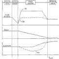
在具有固定传动比变速器的传统车辆中,驾驶员可能在变速器换档(即,调高速档或调低速档)过程中经历传动系统扰动(drivelinedisturbance)。传动系统扰动是因发动机和变速器部件的加速和减速而发生的,这种加速和减速在换档过程中产生惯性扭矩。在调高速档时,由于发动机转速改变,在换档的传动比改变阶段(即惯性阶段),变速器输出扭矩增大,如图1的标号12处所示。这种输出扭矩扰动能被车内的乘客感觉到并且严重地降低了换档质量。In conventional vehicles with fixed ratio transmissions, drivers may experience driveline disturbances during transmission shifts (ie, upshifts or downshifts). Driveline disturbances occur due to the acceleration and deceleration of engine and transmission components, which generate inertial torque during gear changes. When upshifting, due to the change of the engine speed, the transmission output torque increases during the transmission ratio change phase (ie, inertia phase) of the gear shift, as shown at 12 in FIG. 1 . Such output torque disturbances can be felt by occupants in the vehicle and severely degrade shift quality.
发动机减速的幅度越大,则调高速档越快,从而输出换档扭矩扰动的幅度增大。通过减小调高速档过程中产生的发动机扭矩(如标号14处所示),能够抵消惯性扭矩,而且能够使输出换档扭矩的增大降到最小(如标号16处所示),因此提高了换档质量。参照图1所描述的该方法称为“输入扭矩调节”控制。The greater the magnitude of the engine deceleration, the faster the upshift, and thus the greater magnitude of the output shift torque disturbance. By reducing the engine torque generated during an upshift (as indicated at 14), the inertial torque can be counteracted and the increase in output shift torque can be minimized (as indicated at 16), thus increasing shift quality. The method described with reference to FIG. 1 is called "input torque regulation" control.
在调低速档时,当发动机和变速器部件加速到低速档的同步转速时,在传动比改变阶段,变速器输出扭矩减小,如图2的标号18处所示。此外,如标号20处所示,在扭矩传递阶段,随着发动机的加速,变速器输出扭矩在调低速档接近完成时会激增(spike)。在传动比改变阶段输出扭矩的降低能被车内的乘客感觉到,并且给人以进行调低速档时加速不连续的感觉。在调低速档结束时输出扭矩激增会降低换档质量且给乘客一种生硬或粗暴换档的感觉。此外,输出换档扭矩降低的幅度以及在调低速档接近结束时的激增与调低速档的速度成比例地增大。为了在换档结束时减小发动机的加速度,通过利用输入扭矩调节而使发动机燃烧扭矩(combustiontorque)在调低速档接近结束时减小,如标号22处所示。结果是,能够最小化甚至避免变速器输出扭矩的激增,如标号24处所示,因此减小了换档扰动。During a downshift, transmission output torque decreases during the ratio change phase as the engine and transmission components accelerate to the synchronous speed of the low gear, as shown at 18 in FIG. 2 . Additionally, as indicated at 20 , during the torque transfer phase, as the engine accelerates, transmission output torque spikes as the downshift nears completion. The reduction in output torque during the ratio change phase is felt by the occupants of the vehicle and gives the feeling of discontinuous acceleration during downshifts. A surge in output torque at the end of a downshift reduces shift quality and gives the passenger a harsh or rough shift feel. In addition, the magnitude of output shift torque reduction and surge near the end of the downshift increases in proportion to the speed of the downshift. To reduce engine acceleration at the end of the shift, engine combustion torque is reduced near the end of the downshift by utilizing input torque modulation, as indicated at 22 . As a result, surges in transmission output torque, as shown at 24, can be minimized or even avoided, thereby reducing shift disturbances.
在传统车辆的申请文件中,随着换档过程中的输入扭矩调节可能产生的问题包括:由于诸如发热(emission)的其它限制而造成有限的发动机扭矩减少保证(authority)、对扭矩调节请求的迟延或拙劣的发动机扭矩响应、进一步降低了换档质量;并且由于通常利用点火延迟来获得扭矩调节请求,造成了耗费的燃料能量和效率。In conventional vehicle filings, problems that may arise with input torque modulation during a gear shift include: limited engine torque reduction authority due to other constraints such as emission, limitations on torque modulation requests Late or poor engine torque response further degrades shift quality; and wastes fuel energy and efficiency since spark retard is often used to obtain torque modulation requests.
发明内容Contents of the invention
一种在用于机动车辆的动力系统中在换档过程中控制扭矩的方法,该动力系统包括:发动机、电机、具有可驱动地连接至发动机的输入端和可驱动地连接至电机的变速器输出端的变速器、以及可驱动地连接至电机和车轮的动力系统输出端,该方法包括:通过变速器将发动机扭矩传递到动力系统输出端;在换档过程中,操作电机以改变传递到动力系统输出端的扭矩;以及存储换档过程中由电机产生的能量。A method of controlling torque during a gear shift in a powertrain for a motor vehicle, the powertrain comprising: an engine, an electric machine, a transmission output having an input drivably connected to the engine, and a transmission output drivably connected to the electric machine A transmission at the transmission end, and a powertrain output end drivably connected to the electric motor and the wheels, the method comprising: transmitting engine torque to the powertrain output end through the transmission; during a gear shift, operating the electric machine to change the torque; and storing energy generated by the electric motor during gear changes.
在实现所请求的扭矩调节并提供最佳的换档质量的同时,过量的变速器输出扭矩转换成由蓄电池存储的电能。Excess transmission output torque is converted to electrical energy stored by the battery while achieving the requested torque modulation and providing optimum shift quality.
利用产生精确的扭矩调节幅度的电机响应而避免了曲轴扭矩减小的延迟。Delays in crankshaft torque reduction are avoided with an electric motor response that produces precise torque modulation magnitudes.
在某些情况下,电机和发动机均减少总的传动系统输出扭矩换档扰动来满足所请求的扭矩调节水平(level)。这在电机没有被充分利用或蓄电池荷电状态接近最大极限的情况下是有用的。Under certain conditions, both the electric machine and the engine reduce the total driveline output torque shift disturbance to meet the requested torque modulation level. This is useful in situations where the motor is not being fully utilized or the battery state of charge is close to the maximum limit.
从以下详细描述、权利要求和附图中,优选实施例的适用范围将变得显而易见。应当理解,虽然描述了本发明的优选实施例,但是描述和具体实例只是出于示例的目的而给出。对本领域技术人员而言对所描述实施例和实例进行各种改变和修改将变得显而易见。The scope of applicability of the preferred embodiments will become apparent from the following detailed description, claims, and accompanying drawings. It should be understood, that the description and specific examples, while describing preferred embodiments of the invention, are given for purposes of illustration only. Various changes and modifications to the described embodiments and examples will become apparent to those skilled in the art.
附图说明Description of drawings
参照以下结合附图的描述,本发明将变得更易于理解,附图中:With reference to the following description in conjunction with the accompanying drawings, the present invention will become easier to understand, in the accompanying drawings:
图1是示出了在传统车辆传动系统的输入扭矩调节中,在调高速档过程中的变速器输出换档扭矩、齿轮传动比以及发动机扭矩变化的曲线图;1 is a graph showing changes in transmission output shift torque, gear ratio, and engine torque during an upshift in input torque regulation of a conventional vehicle powertrain;
图2是示出了在传统车辆传动系统的输入扭矩调节中,在调低速档过程中的变速器输出换档扭矩、齿轮传动比以及发动机扭矩变化的曲线图;2 is a graph showing transmission output shift torque, gear ratio, and engine torque variation during a downshift in input torque regulation of a conventional vehicle driveline;
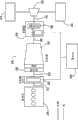
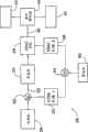
图3是用于RWD HEV的动力系统的示意图;Figure 3 is a schematic diagram of a powertrain for a RWD HEV;
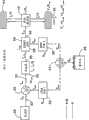
图4是示出了图3的HEV动力系统中的推进力和能量流动的示意图;FIG. 4 is a schematic diagram illustrating propulsion and energy flow in the HEV powertrain of FIG. 3;
图5是示出了表示以模式A操作的动力系统各部件之间的扭矩传递的向量(vector)的示意图;5 is a schematic diagram showing vectors representing torque transfer between components of the powertrain operating in Mode A;
图6是示出了表示以模式B操作的动力系统各部件之间的扭矩传递的向量的示意图;6 is a schematic diagram showing vectors representing torque transfer between components of the powertrain operating in Mode B;
图7是示出了表示以模式D操作的动力系统各部件之间的扭矩传递的向量的示意图;7 is a schematic diagram showing vectors representing torque transfer between components of the powertrain operating in Mode D;
图8A-8D示出了以输出扭矩调节进行变速器调高速档过程中动力系统变量的变化;Figures 8A-8D show the variation of powertrain variables during transmission upshifting with output torque adjustment;
图9A-9D示出了以输出扭矩调节进行变速器调低速档过程中动力系统变量的变化;9A-9D illustrate changes in powertrain variables during a transmission downshift with output torque modulation;
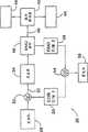
图10是在输出扭矩调节控制过程中用来选择图3中的动力系统操作模式的方法的逻辑流程图;以及10 is a logic flow diagram of a method for selecting the powertrain operating mode of FIG. 3 during output torque regulation control; and
图11是在图3的HEV动力系统中用来提供输出扭矩调节变速器控制的方法的逻辑流程图。11 is a logic flow diagram of a method for providing output torque modulating transmission control in the HEV powertrain of FIG. 3 .
具体实施方式Detailed ways
图3示出了用于混合动力电动车辆的动力系统26,该动力系统包括:内燃机(ICE)28,优选为阿特金森循环(Atkinson cycle)ICE;第一电机30,优选为可驱动地连接至发动机曲轴32且能够交替地用作电动机(motor)和发电机(generator)的曲轴集成起动发电机(CISG);固定传动比的自动变速器34;诸如电动后轴驱动器(ERAD)或电动前轴驱动器(EFAD)的第二电机38,其可驱动地连接至变速器输出轴36且能够交替地用作发动机和发电机;传动系统输出轴40,可驱动地连接至第二电机38;差速器42;车轮44和45,它们可驱动地连接至差速器42。Figure 3 shows a
在变速器换档过程中,可以控制接合至变速器输出端的电机38,以精确地实现变速器扭矩调节请求并减少40处的传动系统输出扭矩换档扰动。通过利用电机30、38以及动力系统26,能够减小变速器输出轴36上的扭矩扰动并能够获得最佳的换档质量。变速器输出端也可以采用具有至少一台电机的包括RWD(后轮驱动)、FWD(前轮驱动)、或AWD(全轮驱动)完全级或轻度级HEV的其它配置。此外,本发明不局限于任何具体的变速器技术且包括传统的自动双离合器(即,动力换档)以及无级自动变速器。During a transmission shift, the
图4示出了动力系统26中的动力和能量流动。发动机28产生的动力和CISG 30产生的动力在50处结合并传送至变速器输入端52。电机30、38产生的电能可在54处结合用来给蓄电池56充电,或者电能从蓄电池被传递到电机30、38。ERAD 38产生的机械能通过ERAD传动装置58传递并通过后面的最终驱动器(final drive)42传递给车轮44、45处的负载。FIG. 4 illustrates power and energy flow in
图3中示出的RWD-HEV CISG/ERAD平台优选地包括阿特金森循环(4.6L,3V)内燃机、固定传动比的六档自动变速器以及两台电机。第一电机30(CISG)集成在发动机28的输出端32且连接至扭矩有级变速器(torque converter transmission)的推进器60,从而提供电动机/发电机的能力。第二电机38(ERAD)通过连接至最终驱动器的行星齿轮组58而接合至变速器34的输出端36,从而在电力驱动或混合动力驱动模式中提供额外的推进力。The RWD-HEV CISG/ERAD platform shown in Figure 3 preferably includes an Atkinson cycle (4.6L, 3V) internal combustion engine, a fixed-ratio six-speed automatic transmission, and two electric machines. A first electric machine 30 (CISG) is integrated at the
这种动力系统配置的主要操作模式包括:利用ERAD驱动(motoring)/发电的电力驱动;利用发动机运转、CISG发电、以及ERAD驱动/发电的串联混合动力驱动;利用CISG&ERAD停止和常规驱动的发动机驱动;利用发动机运转以及CISG和ERAD驱动的并联混合动力驱动;利用CISG驱动以起动发动机以及发动机发动(cranking)的发动机起动(starting);以及利用发动机发动或停止的发动机停止。The main modes of operation for this powertrain configuration include: electric drive with ERAD motoring/generation; series hybrid drive with engine running, CISG generation, and ERAD motoring/generation; engine drive with CISG & ERAD stop and conventional drive ; parallel hybrid drive with engine running and CISG and ERAD drive; engine starting with CISG drive to start the engine and engine cranking; and engine stop with engine cranking or stop.
如图5-7所示,在变速器换档过程中,采用动力系统10的操作模式来提供变速器输出扭矩调节。根据换档的类型(即调高速档或调低速档)、扭矩调节请求的水平、ERAD操作状况、蓄电池状况、以及其它因素,将采用适当的动力系统操作模式来提供期望的输出扭矩调节请求。As shown in FIGS. 5-7 , during a transmission shift, the operating mode of the powertrain 10 is employed to provide transmission output torque modulation. Depending on the type of shift (ie, upshift or downshift), level of torque modulation request, ERAD operating conditions, battery condition, and other factors, the appropriate powertrain operating mode will be employed to provide the desired output torque modulation request.
图5是动力系统26的示意图,示出了表示在操作模式A期间各部件之间的扭矩传递的向量,其中,输出扭矩调节随着ERAD 38在换档过程中减小传动系统输出扭矩而发生。5 is a schematic diagram of
图6是动力系统26的示意图,示出了表示在操作模式B期间各部件之间的扭矩传递的向量,其中,输出扭矩调节随着ERAD 38在换档过程中增大传动系统输出扭矩而发生。6 is a schematic diagram of
图7是动力系统26的示意图,示出了表示在操作模式D期间各部件之间的扭矩传递的向量,其中,扭矩调节仅随着发动机28在换档过程中减小传动系统输出扭矩而发生。7 is a schematic diagram of
图8A-8D示出了变速器调高速档的实例,其中,输出扭矩调节由采用图5所示操作模式A的动力路径的ERAD 38提供。在操作模式A中,ERAD 38通过用作发电机而提供输出扭矩调节且它还提供如70处所示的负扭矩,该负扭矩在换档过程中减小了变速器输出扭矩扰动72,从而提供平滑的总传动系统输出扭矩74,前提是ERAD适用于该目的。如果ERAD 38的当前温度低于其发热极限、其转速低于其运行转速极限、而且蓄电池56的荷电状态(SOC)低于最大允许SOC极限,则ERAD 38是适用的。8A-8D illustrate examples of transmission upshifts in which output torque regulation is provided by the ERAD 38 employing the power path of operating mode A shown in FIG. 5 . In operating mode A, the ERAD 38 provides output torque regulation by acting as a generator and it also provides a negative torque as shown at 70 which reduces the transmission
通过利用操作模式A,过量的变速器输出扭矩76被转换成由蓄电池56存储的电能,同时获得了所请求的扭矩调节并提供了最佳的换档质量。此外,利用产生精确的扭矩调节幅度的ERAD的灵敏度,避免了曲轴扭矩减小的延迟。在操作模式A中,还可以利用ERAD 38和发动机28来减小总传动系统输出扭矩换档扰动72,从而满足所请求的扭矩调节水平。发动机28和ERAD 38的这种组合在ERAD没有被充分利用或蓄电池SOC接近其最大极限的情况下是有用的。By utilizing operating mode A, excess
图9A-9D示出了变速器调低速档的实例,其中,输出扭矩调节由采用操作模式A和B的ERAD 38提供。在调低速档的传动比改变阶段,在驱动模式中,ERAD 38可以采用操作模式B以产生ERAD输出扭矩80,从而使净总传动系统输出扭矩82增大以抵消或补偿通常在调低速档的传动比改变阶段出现的变速器输出扭矩的减小84。只有当ERAD 38适用于该目的时才采用操作模式B。如果ERAD38的当前温度低于其发热极限、其转速低于其运行转速极限,而且蓄电池56的荷电状态(SOC)高于最小允许SOC极限,则ERAD 38是适用的。9A-9D illustrate examples of transmission downshifts in which output torque regulation is provided by the
在接近调低速档完成的扭矩传递阶段,动力系统26转换为操作模式A,从而ERAD用作发电机而产生负扭矩86,该负扭矩使净总传动系统输出扭矩减小,从而减弱或消除通常在没有扭矩调节时出现的输出扭矩激增88。与传统情况不同,通过HEV,该过量的扭矩89被转换成由蓄电池56存储的电能,同时满足了所请求的扭矩调节并提供了最佳的换档质量。During the torque transfer phase near the completion of the downshift, the
图10示出了用来提供图3中的HEV动力系统26的输出扭矩调节变速器控制的方法的步骤。在开始执行该方法并在步骤90获得动力系统10的操作状况后,在步骤92进行检测以确定变速器34的齿轮传动比改变是否已被响应于车辆参数以及与这些车辆参数有关的优选齿轮传动比的列表而运作的变速器控制器请求,这些车辆参数包括但不局限于发动机节流阀位置、油门踏板位置、车速、发动机转速、手动操作的档位选择器的位置。FIG. 10 illustrates steps in a method for providing output torque regulating transmission control of the
如果92的检测结果在逻辑上为肯定,则控制继续步骤94,在该步骤进行检测以确定换档输出扭矩调节是否被控制器请求。如果92或94的检测结果在逻辑上为否定,则控制返回到步骤90。但是,如果94的检测结果为肯定,则在步骤96确定所期望的输出扭矩调节幅度。所期望的输出扭矩调节幅度取决于换档的进展。例如,在调高速档的传动比改变阶段开始时,所期望的幅度将随着传动比改变阶段的继续从零缓变到负稳态水平,并且随着传动比改变阶段的结束将缓变回到零。If the test at 92 is logically positive, control continues at
在步骤98,参照当前的操作参数和所期望的输出扭矩调节幅度,根据图11的方法选择动力系统26的操作模式。At
在步骤100,将动力系统26设置在由图11的方法所选择的期望的操作模式,从而在换档过程中提供所期望的输出扭矩调节。At
下面参照图11所示的用来选择期望的操作模式的方法,在步骤102进行检测以确定ERAD 38的温度是否低于表征ERAD的最大允许操作温度的参考温度。Referring now to the method for selecting a desired mode of operation shown in FIG. 11, a test is performed at
如果102的检测结果是肯定的,则在步骤104进行检测以确定ERAD 38的转速是否低于表征ERAD的最大允许操作转速的参考转速。If the detection result of 102 is affirmative, then a detection is performed at
如果104的检测结果是肯定的,则在步骤106进行检测以确定变速器输出扭矩调节的请求幅度是否小于表征ERAD 38的当前最大扭矩容量(capability)的参考扭矩极限。If the test at 104 is affirmative, a test is made at
如果102、104和106的任一检测结果是否定的,则控制进行步骤108,在该步骤动力系统10设置为操作模式D,在操作模式D中仅发动机28产生的扭矩传递给变速器输出端36,而没有对由曲轴52传递给变速器输入端52的扭矩产生任何影响的CISG 30扭矩,即,CISG 30既不产生也不汲取动力。图7所示的操作模式D是传统车辆的操作模式,而且由于不能使用CISG 30和ERAD 38,发动机扭矩将减小从而提供所期望的输出扭矩调节水平。If any of 102, 104 and 106 are negative, control proceeds to step 108 where powertrain 10 is set to operating mode D in which only torque produced by
如果106的检测结果是肯定的,则在步骤110进行检测以确定所期望的变速器输出扭矩调节幅度是否为负。如果110的检测结果是肯定的,表明所期望的输出扭矩调节水平为负,则在步骤112进行检测以确定蓄电池的SOC是否低于最大许可SOC参考值。If the result of the test at 106 is affirmative, a test is performed at
如果112的检测结果是肯定的,表明蓄电池的SOC可进一步增大同时ERAD 38起发电机的作用,则在步骤114选择操作模式A作为动力系统26的操作模式,而且在调高速档过程中,通过将发动机12产生的动力转换为蓄电池56存储的电能,ERAD 38执行输出扭矩调节,同时获得所期望的输出扭矩调节水平。If the test result of 112 is affirmative, indicating that the SOC of the battery can be further increased while the
如果112的检测结果是否定的,表明蓄电池的SOC不能进一步增大,则控制进行步骤116,在该步骤动力系统26设置为操作模式D,在操作模式D中,仅发动机12产生的扭矩传递给输出轴40,而没有ERAD参与扭矩调节。If the test result at 112 is negative, indicating that the SOC of the battery cannot be increased further, then control proceeds to step 116, where the
如果110的检测结果是否定的,表明所期望的输出扭矩调节水平为正且输出轴40的扭矩将增大,则在步骤118进行检测以确定蓄电池的SOC是否大于最小SOC。If the test at 110 is negative, indicating that the desired output torque adjustment level is positive and the
如果118的检测结果是肯定的,表明蓄电池的SOC可进一步增大,则控制进行步骤120。在步骤120选择操作模式B,表明在调低速档的过程中,通过补充发动机28产生的动力,可使ERAD 38起电动机的作用并参与输出扭矩调节。If the test result at 118 is affirmative, indicating that the SOC of the battery can be further increased, then control proceeds to step 120 . Selecting operating mode B at
如果118的检测结果是否定的,表明已经达到最小蓄电池SOC极限,则控制进行步骤108,在该步骤将动力系统26设置为操作模式D的,在操作模式D中,发动机28产生的扭矩传递给输出轴40,而没有对由输出轴40传递的扭矩产生任何改变的ERAD 38。If the test result of 118 is negative, indicating that the minimum battery SOC limit has been reached, control proceeds to step 108, where the
输出扭矩调节控制可应用于包括至少一个可驱动地连接到变速器输出端36的电机的RWD、FWD、AWD完全级或轻度级HEV动力系统配置。此外,控制策略不限于任何具体的变速器技术,而能够应用于传统的自动变速器、双离合器动力换档变速器、以及无级自动变速器。The output torque regulation control is applicable to RWD, FWD, AWD full grade or mild grade HEV powertrain configurations including at least one electric machine drivably connected to the
根据专利法律的规定已经描述了优选实施例。然而,应当注意,除了具体图示和描述的实施例之外,替代实施例也是可行的。The preferred embodiments have been described in accordance with the provisions of the patent laws. It should be noted, however, that alternative embodiments are possible in addition to the embodiment specifically shown and described.
Claims (20)
Applications Claiming Priority (2)
| Application Number | Priority Date | Filing Date | Title |
|---|---|---|---|
| US12/163,132US8137236B2 (en) | 2008-06-27 | 2008-06-27 | Ouput torque modulation control of a transmission in a hybrid electric vehicle |
| US12/163,132 | 2008-06-27 |
Publications (2)
| Publication Number | Publication Date |
|---|---|
| CN101612936A CN101612936A (en) | 2009-12-30 |
| CN101612936Btrue CN101612936B (en) | 2014-07-02 |
Family
ID=41448157
Family Applications (1)
| Application Number | Title | Priority Date | Filing Date |
|---|---|---|---|
| CN200910149033.1AExpired - Fee RelatedCN101612936B (en) | 2008-06-27 | 2009-06-12 | Regulation and control of output torque of transmission in hybrid power electrical vehicle |
Country Status (2)
| Country | Link |
|---|---|
| US (1) | US8137236B2 (en) |
| CN (1) | CN101612936B (en) |
Families Citing this family (19)
| Publication number | Priority date | Publication date | Assignee | Title |
|---|---|---|---|---|
| US8214116B2 (en)* | 2007-07-11 | 2012-07-03 | GM Global Technology Operations LLC | Apparatus and method for decreasing an upshift delay in an automatic transmission |
| US9459787B2 (en)* | 2008-12-03 | 2016-10-04 | Kelsey-Hayes Company | Control knob |
| DE102010015294B4 (en) | 2010-04-17 | 2018-04-05 | GM Global Technology Operations LLC (n. d. Ges. d. Staates Delaware) | Vehicle with energy management to support the energy balance and process to support the energy balance of a vehicle |
| US8647231B2 (en)* | 2010-07-07 | 2014-02-11 | Ford Global Technologies, Llc | Transitioning between electric-drive and parallel-drive in a hybrid-electric vehicle powertrain |
| US9242545B2 (en)* | 2010-10-20 | 2016-01-26 | GM Global Technology Operations LLC | Negative-torque downshift execution for fixed-gear transmissions |
| DE102012018416B4 (en)* | 2012-09-12 | 2015-04-23 | Getrag Getriebe- Und Zahnradfabrik Hermann Hagenmeyer Gmbh & Cie Kg | Method for driving a hybrid drive train |
| CN103963778B (en)* | 2013-02-04 | 2015-04-08 | 广州汽车集团股份有限公司 | Hybrid vehicle shifting assistance control method and corresponding hybrid vehicle |
| US9766052B2 (en) | 2013-04-22 | 2017-09-19 | Ford Global Technologies, Llc | System and method for determining rotor position offset of an electric machine |
| DE102015009901A1 (en)* | 2015-07-29 | 2017-02-02 | Audi Ag | Method for operating a hybrid drive device for a motor vehicle and corresponding hybrid drive device |
| US10166855B2 (en)* | 2015-09-12 | 2019-01-01 | GM Global Technology Operations LLC | Vehicle, system, and method of calculating an engine torque request value |
| US10513256B2 (en) | 2017-03-09 | 2019-12-24 | Ford Global Technologies, Llc | Methods and system for improving hybrid vehicle transmission gear shifting |
| US10919518B2 (en) | 2017-03-09 | 2021-02-16 | Ford Global Technologies, Llc | Methods and system for improving hybrid vehicle transmission gear shifting |
| CN111120644B (en)* | 2018-11-01 | 2021-05-25 | 郑州宇通客车股份有限公司 | Power-interruption-free gear shifting control method and system for hybrid vehicle |
| GB201820881D0 (en)* | 2018-12-20 | 2019-02-06 | Agco Int Gmbh | EPowershift driveline |
| DE102019203730A1 (en)* | 2019-03-19 | 2020-09-24 | Zf Friedrichshafen Ag | Method for operating a drive train for a work machine, drive train for a work machine and work machine |
| DE102019203724A1 (en)* | 2019-03-19 | 2020-09-24 | Zf Friedrichshafen Ag | Method for operating a drive train for a work machine, drive train for a work machine and work machine |
| CN110925417A (en)* | 2020-02-19 | 2020-03-27 | 盛瑞传动股份有限公司 | Auxiliary control method for torque reduction in unpowered upshift process of P2 hybrid power transmission |
| US20220314964A1 (en)* | 2021-03-31 | 2022-10-06 | Flux Hybrids Inc. | Apparatus and System for Integrating An Electric Motor Into A Vehicle |
| WO2024251513A1 (en)* | 2023-06-06 | 2024-12-12 | Zf Cv Systems Global Gmbh | Control device and method for operating a control device, transmission control arrangement, motor vehicle and computer program |
Citations (2)
| Publication number | Priority date | Publication date | Assignee | Title |
|---|---|---|---|---|
| US5943918A (en)* | 1997-12-01 | 1999-08-31 | Chrysler Corporation | Powertrain system for a hybrid electric vehicle |
| CN1910065A (en)* | 2004-01-23 | 2007-02-07 | 易通公司 | Hybrid powertrain system including smooth shifting automated transmission |
Family Cites Families (6)
| Publication number | Priority date | Publication date | Assignee | Title |
|---|---|---|---|---|
| US6945893B2 (en)* | 2002-05-28 | 2005-09-20 | Eaton Corporation | Hybrid powertrain system |
| WO2005106290A1 (en)* | 2004-04-27 | 2005-11-10 | Toyota Jidosha Kabushiki Kaisha | Controller of driving gear for vehicle |
| JP4244961B2 (en)* | 2005-05-26 | 2009-03-25 | トヨタ自動車株式会社 | Control device for vehicle drive device |
| DE102005032196A1 (en)* | 2005-07-09 | 2007-01-18 | Bayerische Motoren Werke Ag | Drive device for a motor vehicle |
| JPWO2008026480A1 (en)* | 2006-08-30 | 2010-01-21 | アイシン精機株式会社 | Vehicle drive source control device |
| JP4645620B2 (en)* | 2007-05-24 | 2011-03-09 | トヨタ自動車株式会社 | Control device for power transmission device for hybrid vehicle |
- 2008
- 2008-06-27USUS12/163,132patent/US8137236B2/ennot_activeExpired - Fee Related
- 2009
- 2009-06-12CNCN200910149033.1Apatent/CN101612936B/ennot_activeExpired - Fee Related
Patent Citations (2)
| Publication number | Priority date | Publication date | Assignee | Title |
|---|---|---|---|---|
| US5943918A (en)* | 1997-12-01 | 1999-08-31 | Chrysler Corporation | Powertrain system for a hybrid electric vehicle |
| CN1910065A (en)* | 2004-01-23 | 2007-02-07 | 易通公司 | Hybrid powertrain system including smooth shifting automated transmission |
Also Published As
| Publication number | Publication date |
|---|---|
| US20090325760A1 (en) | 2009-12-31 |
| US8137236B2 (en) | 2012-03-20 |
| CN101612936A (en) | 2009-12-30 |
Similar Documents
| Publication | Publication Date | Title |
|---|---|---|
| CN101612936B (en) | Regulation and control of output torque of transmission in hybrid power electrical vehicle | |
| US8224513B2 (en) | Torque modulation control of a hybrid electric vehicle | |
| JP4063744B2 (en) | Control device for hybrid vehicle | |
| US9090247B2 (en) | Control apparatus for vehicular drive system | |
| JP4127142B2 (en) | Control device for hybrid vehicle | |
| US9056610B2 (en) | Transmission downshift input torque modulation for a hybrid electric vehicle | |
| US8061462B2 (en) | Transmission upshift input torque modulation for a hybrid electric vehicle | |
| CN100412419C (en) | Over-Neutral Switching Control in Electric Variable Transmission | |
| JP3377040B2 (en) | Hybrid vehicle control device | |
| US9643591B2 (en) | Speed change control system and speed change control method for hybrid vehicle | |
| CN102227344B (en) | Power transmission apparatus for vehicle | |
| JP4293274B2 (en) | Control device for vehicle drive device | |
| JP4683137B2 (en) | Power transmission control device | |
| CN101296830A (en) | Control system for vehicle drive device | |
| JP6798448B2 (en) | Vehicle control device | |
| JP5233658B2 (en) | Engine start control device for hybrid vehicle | |
| JP6476154B2 (en) | Hybrid vehicle | |
| JP7014016B2 (en) | Hybrid vehicle | |
| JP6853139B2 (en) | Vehicle control device | |
| US20170072939A1 (en) | Hybrid vehicle | |
| WO2012140665A1 (en) | A method for delivering power through a hybrid drive and system thereof | |
| JP2010013002A (en) | Hybrid drive apparatus and drive control device | |
| JP4299288B2 (en) | POWER OUTPUT DEVICE, AUTOMOBILE MOUNTING THE SAME, DRIVE DEVICE, AND CONTROL METHOD FOR POWER OUTPUT DEVICE | |
| CN108150641A (en) | The speed-change control device of vehicle | |
| JP4597043B2 (en) | Vehicle, drive device, and vehicle control method |
Legal Events
| Date | Code | Title | Description |
|---|---|---|---|
| C06 | Publication | ||
| PB01 | Publication | ||
| C10 | Entry into substantive examination | ||
| SE01 | Entry into force of request for substantive examination | ||
| C14 | Grant of patent or utility model | ||
| GR01 | Patent grant | ||
| CF01 | Termination of patent right due to non-payment of annual fee | Granted publication date:20140702 | |
| CF01 | Termination of patent right due to non-payment of annual fee |