CN101611277B - Free-cooling limitation control for air conditioning systems - Google Patents
Free-cooling limitation control for air conditioning systemsDownload PDFInfo
- Publication number
- CN101611277B CN101611277BCN2006800569139ACN200680056913ACN101611277BCN 101611277 BCN101611277 BCN 101611277BCN 2006800569139 ACN2006800569139 ACN 2006800569139ACN 200680056913 ACN200680056913 ACN 200680056913ACN 101611277 BCN101611277 BCN 101611277B
- Authority
- CN
- China
- Prior art keywords
- temperature difference
- free
- cooling mode
- expansion device
- temperature
- Prior art date
- Legal status (The legal status is an assumption and is not a legal conclusion. Google has not performed a legal analysis and makes no representation as to the accuracy of the status listed.)
- Expired - Fee Related
Links
Images
Classifications
- F—MECHANICAL ENGINEERING; LIGHTING; HEATING; WEAPONS; BLASTING
- F25—REFRIGERATION OR COOLING; COMBINED HEATING AND REFRIGERATION SYSTEMS; HEAT PUMP SYSTEMS; MANUFACTURE OR STORAGE OF ICE; LIQUEFACTION SOLIDIFICATION OF GASES
- F25B—REFRIGERATION MACHINES, PLANTS OR SYSTEMS; COMBINED HEATING AND REFRIGERATION SYSTEMS; HEAT PUMP SYSTEMS
- F25B25/00—Machines, plants or systems, using a combination of modes of operation covered by two or more of the groups F25B1/00 - F25B23/00
- F—MECHANICAL ENGINEERING; LIGHTING; HEATING; WEAPONS; BLASTING
- F25—REFRIGERATION OR COOLING; COMBINED HEATING AND REFRIGERATION SYSTEMS; HEAT PUMP SYSTEMS; MANUFACTURE OR STORAGE OF ICE; LIQUEFACTION SOLIDIFICATION OF GASES
- F25B—REFRIGERATION MACHINES, PLANTS OR SYSTEMS; COMBINED HEATING AND REFRIGERATION SYSTEMS; HEAT PUMP SYSTEMS
- F25B41/00—Fluid-circulation arrangements
- F—MECHANICAL ENGINEERING; LIGHTING; HEATING; WEAPONS; BLASTING
- F25—REFRIGERATION OR COOLING; COMBINED HEATING AND REFRIGERATION SYSTEMS; HEAT PUMP SYSTEMS; MANUFACTURE OR STORAGE OF ICE; LIQUEFACTION SOLIDIFICATION OF GASES
- F25B—REFRIGERATION MACHINES, PLANTS OR SYSTEMS; COMBINED HEATING AND REFRIGERATION SYSTEMS; HEAT PUMP SYSTEMS
- F25B2400/00—General features or devices for refrigeration machines, plants or systems, combined heating and refrigeration systems or heat-pump systems, i.e. not limited to a particular subgroup of F25B
- F25B2400/04—Refrigeration circuit bypassing means
- F25B2400/0401—Refrigeration circuit bypassing means for the compressor
- F—MECHANICAL ENGINEERING; LIGHTING; HEATING; WEAPONS; BLASTING
- F25—REFRIGERATION OR COOLING; COMBINED HEATING AND REFRIGERATION SYSTEMS; HEAT PUMP SYSTEMS; MANUFACTURE OR STORAGE OF ICE; LIQUEFACTION SOLIDIFICATION OF GASES
- F25B—REFRIGERATION MACHINES, PLANTS OR SYSTEMS; COMBINED HEATING AND REFRIGERATION SYSTEMS; HEAT PUMP SYSTEMS
- F25B2600/00—Control issues
- F25B2600/25—Control of valves
- F25B2600/2513—Expansion valves
- F—MECHANICAL ENGINEERING; LIGHTING; HEATING; WEAPONS; BLASTING
- F25—REFRIGERATION OR COOLING; COMBINED HEATING AND REFRIGERATION SYSTEMS; HEAT PUMP SYSTEMS; MANUFACTURE OR STORAGE OF ICE; LIQUEFACTION SOLIDIFICATION OF GASES
- F25B—REFRIGERATION MACHINES, PLANTS OR SYSTEMS; COMBINED HEATING AND REFRIGERATION SYSTEMS; HEAT PUMP SYSTEMS
- F25B2700/00—Sensing or detecting of parameters; Sensors therefor
- F25B2700/21—Temperatures
- F25B2700/2106—Temperatures of fresh outdoor air
- F—MECHANICAL ENGINEERING; LIGHTING; HEATING; WEAPONS; BLASTING
- F25—REFRIGERATION OR COOLING; COMBINED HEATING AND REFRIGERATION SYSTEMS; HEAT PUMP SYSTEMS; MANUFACTURE OR STORAGE OF ICE; LIQUEFACTION SOLIDIFICATION OF GASES
- F25B—REFRIGERATION MACHINES, PLANTS OR SYSTEMS; COMBINED HEATING AND REFRIGERATION SYSTEMS; HEAT PUMP SYSTEMS
- F25B2700/00—Sensing or detecting of parameters; Sensors therefor
- F25B2700/21—Temperatures
- F25B2700/2117—Temperatures of an evaporator
- F25B2700/21171—Temperatures of an evaporator of the fluid cooled by the evaporator
- F25B2700/21173—Temperatures of an evaporator of the fluid cooled by the evaporator at the outlet
Landscapes
- Engineering & Computer Science (AREA)
- Physics & Mathematics (AREA)
- Mechanical Engineering (AREA)
- Thermal Sciences (AREA)
- General Engineering & Computer Science (AREA)
- Air Conditioning Control Device (AREA)
Abstract
Translated fromChinese
Description
Translated fromChinese【技术领域】【Technical field】
本发明涉及空调系统。更具体地说,本发明涉及用于控制具有自由冷却模式和冷却模式的空调系统的方法和系统。The present invention relates to air conditioning systems. More specifically, the present invention relates to a method and system for controlling an air conditioning system having a free cooling mode and a cooling mode.
【背景技术】【Background technique】
空调系统通过消耗能源运行来冷却特定容量的空气。通常情况下,空调系统的工作在冷冻或冷却模式(chiller or cooling mode),其包括将制冷剂循环通过热力循环。在循环期间,热量和功被传递给制冷剂。制冷剂进入热交换器并冷却工作流体(例如水),这反过来又可被用来降温空调的空间。一般是使用压缩机将功传递给制冷剂。Air conditioning systems operate by expending energy to cool a specific volume of air. Typically, air conditioning systems operate in a chiller or cooling mode, which involves circulating a refrigerant through a thermodynamic cycle. During the cycle, heat and work are transferred to the refrigerant. The refrigerant enters the heat exchanger and cools the working fluid (such as water), which in turn can be used to cool the air-conditioned space. Typically a compressor is used to transfer work to the refrigerant.
然而,当外部环境空气的温度低时,在压缩机不参与的情况下外部空气可以被用来冷却制冷剂。当外部环境空气被空调系统用来冷却制冷剂时,该系统被称为工作在自由冷却模式。由于使空调系统工作在自由冷却模式需要投入较少的功,使空调系统工作在自由冷却模式比使空调系统工作在冷却模式更有效率。However, when the temperature of the outside ambient air is low, the outside air can be used to cool the refrigerant without the involvement of the compressor. When the outside ambient air is used by the air conditioning system to cool the refrigerant, the system is said to be operating in free cooling mode. Since less work is required to operate the air conditioning system in the free cooling mode, it is more efficient to operate the air conditioning system in the free cooling mode than in the cooling mode.
传统上,即使当外部环境空气的温度低时,空调系统已经运行在冷却模式。在这种条件下,运行在冷却模式提供了调节制冷剂的低效率手段。相比之下,在这种条件下,使空调系统运行在自由冷却模式则更为有效。在自由冷却模式,一个或多个通风的换热器和泵被激活,并且在整个空调系统循环的制冷剂被外部环境空气冷却,而无需压缩机。Traditionally, air conditioning systems have been operating in cooling mode even when the temperature of the outside ambient air is low. Under such conditions, operating in cooling mode provides an inefficient means of conditioning the refrigerant. In contrast, it is more efficient to run the air conditioning system in free cooling mode under these conditions. In free cooling mode, one or more vented heat exchangers and pumps are activated, and the refrigerant circulating throughout the air conditioning system is cooled by the outside ambient air without the need for a compressor.
空调机组可配置为使用冷却模式和自由冷却模式工作。因此,需要提高具有自由冷却模式的空调系统的效率和控制的方法和系统。Air conditioning units can be configured to work in cooling mode and free cooling mode. Therefore, there is a need for methods and systems to improve the efficiency and control of air conditioning systems having free cooling modes.
【发明内容】【Content of invention】
空调系统和控制方法被提供为:当工作在自由冷却模式时,包括自由冷却限制和改变程序(sequence),至少根据离开空调系统的工作流体和外部环境空气之间的温差,改变膨胀装置的开口。An air conditioning system and control method are provided that, when operating in a free cooling mode, include free cooling limitation and altering the sequence to vary the opening of the expansion device based at least on the temperature difference between the working fluid leaving the air conditioning system and external ambient air .
具有冷却模式和自由冷却模式的空调系统被提供。该系统包括制冷回路,该制冷回路具有压缩机、泵、具有可变的开口的膨胀装置和控制器。该控制器选择性地经由压缩机通过将制冷剂循环和压缩经过制冷回路使系统工作在经由冷却模式,或经由泵通过使制冷剂循环经过制冷回路使系统工作在自由冷却模式。自由冷却限制和改变程序存储在控制器,并且至少根据温差改变可变的开口。An air conditioning system with cooling mode and free cooling mode is provided. The system includes a refrigeration circuit having a compressor, a pump, an expansion device with a variable opening, and a controller. The controller selectively operates the system in a cooling mode by circulating and compressing the refrigerant through the refrigeration circuit via the compressor or in a free cooling mode by circulating the refrigerant through the refrigeration circuit via the pump. A free cooling limit and change program is stored in the controller, and the variable opening is changed at least according to the temperature difference.
控制具有冷却模式和自由冷却模式的空调系统的方法也被提供。该方法包括确定外部环境空气和被调节的工作流体之间的温差,当温差低于第一预定水平时,使系统工作在冷却模式,当温差超过第二预定水平时,使系统工作在制冷剂膨胀装置完全打开的自由冷却模式下,以及当温差处于第一第二预定水平之间时,根据温差部分地开放制冷剂膨胀装置以使该系统工作在自由冷却模式。A method of controlling an air conditioning system having a cooling mode and a free cooling mode is also provided. The method includes determining a temperature difference between external ambient air and a conditioned working fluid, operating the system in a cooling mode when the temperature difference is below a first predetermined level, and operating the system in a refrigerant mode when the temperature difference exceeds a second predetermined level In the free cooling mode with the expansion device fully opened, and when the temperature difference is between the first and second predetermined levels, partially opening the refrigerant expansion device according to the temperature difference to operate the system in the free cooling mode.
从以下的详细说明、附图、以及所附的权利要求,本领域的技术人员将体会和理解本发明的上述及其他特点和优点。Those skilled in the art will appreciate and understand the above and other features and advantages of the present invention from the following detailed description, drawings, and appended claims.
【附图说明】【Description of drawings】
图1是根据本发明在自由冷却模式的空调系统的示范的实施方案;Figure 1 is an exemplary embodiment of an air conditioning system in free cooling mode according to the invention;
图2是根据本发明在冷却模式的空调系统的示范的实施方案;Figure 2 is an exemplary embodiment of an air conditioning system in cooling mode according to the invention;
图3说明操作图1和2的空调系统的方法的示范的实施方案;及Figure 3 illustrates an exemplary embodiment of a method of operating the air conditioning system of Figures 1 and 2; and
图4是说明图1和2的空调系统的示范的自由冷却工作范围的图表。FIG. 4 is a graph illustrating an exemplary free cooling operating range for the air conditioning system of FIGS. 1 and 2 .
【具体实施方式】【Detailed ways】
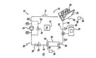
现在参考附图,特别是参考图1和2,其显示了空调系统(参考标号一般为10)的示范的实施方案。系统10被配置为工作在自由冷却模式12(图1)和冷却模式14(图2)。Referring now to the drawings, and in particular to FIGS. 1 and 2, there is shown an exemplary embodiment of an air conditioning system (generally referenced at 10). System 10 is configured to operate in free cooling mode 12 (FIG. 1) and cooling mode 14 (FIG. 2).
系统10包括用于选择在自由冷却和冷却模式12、14之间切换的控制器16。优越之处在于,控制器16包括监控系统10内一个或多个条件的限制和改变控制程序18,当工作在自由冷却模式12时,并调整膨胀装置的开口的大小以在系统10内保持足够的压力并防止损坏泵。以这种方式,与先前技术的系统相比,限制和改变控制程序18在自由冷却模式12期间提高了系统10的性能。System 10 includes a
系统10包括制冷回路20,该制冷回路20具有冷凝器22、泵24、膨胀装置26、蒸发器28、和压缩机30。控制器16被配置为选择性地控制泵24(当在自由冷却模式12时)或者压缩机30(当在冷却模式14时)来使制冷剂在流动方向(D)通过系统10流通。因此,当在自由冷却模式12时,系统10控制泵24来使制冷剂在流动方向D流通。然而,当在冷却模式14时,系统10控制压缩机30来压缩和使制冷剂在流动方向D流通。因为自由冷却模式12不需要输入额外的功来使压缩机30工作,自由冷却模式12比冷却模式14使用更少的能量。System 10 includes a
系统10包括压缩机旁路循环32和泵旁路回路34。系统10包括被控制器16控制的一个或多个阀门36,使控制器能够根据需要有选择性地定位阀36以选择性地打开和关闭旁路回路32、34。System 10 includes
在冷却模式14,控制器16控制阀36,从而使压缩机旁路回路32关闭且使泵旁路回路34开放。在这种配置中,系统10允许压缩机30来压缩和使制冷剂通过流经泵旁路回路34在流动方向D流通。In cooling mode 14 ,
相比之下,当在自由冷却模式12时,控制器16控制阀36,从而使压缩机旁路回路32开放且使泵旁路回路34关闭。在这种配置中,系统10允许泵24来使制冷剂通过流经压缩机旁路回路32在流动方向D流通。In contrast, when in
因此,系统10在蒸发器28中提供制冷剂44和工作流体46之间的热传递。热被从工作流体46传递至制冷剂44,冷却工作流体46。冷却的工作流体46在出口48离开蒸发器28,流通整个需要降温的区域,并通过入口50返回到蒸发器。这一过程既在自由冷却模式12中又在冷却模式中发生。制冷剂44可以是R22、R410A、或任何其他已知的制冷剂。工作流体46可以是空气、水、乙二醇、或任何其他本技术领域已知的流体。Thus, system 10 provides heat transfer between refrigerant 44 and working
在冷却模式14中,系统10像本技术领域已知的标准的蒸汽压缩(vapor-compression)空调系统一样工作,经由膨胀装置26的制冷剂的压缩和膨胀被用于调节工作流体46。膨胀装置26可以是任何已知的膨胀装置,例如但不限于可控的膨胀装置(如热力膨胀阀)。在一个优选的实施方案中,膨胀装置26是电子可控的膨胀阀。在另一优选实施方案中,膨胀装置26是双路阀。在膨胀装置26是可控的膨胀装置的例子中,膨胀装置最好由控制器16控制。In cooling mode 14 , system 10 operates like a standard vapor-compression air conditioning system known in the art, with compression and expansion of the refrigerant via expansion device 26 being used to condition working
在自由冷却模式12中,系统10利用外部环境空气40的热去除能力,其在于经由一个或多个风扇42与冷凝器22的热交换关系中。自由冷却模式12的功效取决于外部环境空气40的温度52和当工作流体46通过出口48离开蒸发器28时的温度(离开温度54)之间的差异或温差(德耳塔T或ΔT)。也就是说,ΔT=(离开温度54)-(外部空气温度52)。通常,在ΔT值越高下,自由冷却模式12越有效。In
在一个示范的实施方案中,ΔT是使用第一温度传感器56和第二温度传感器58被确定的。第一温度传感器56被安置来测量外部空气温度52,而第二温度传感器58被安置来测量离开温度54。优选地,控制器16与第一和第二温度传感器56、58接口来计算ΔT。第一和第二温度传感器56、58可以是任何本技术领域已知的温度敏感元件,包括但不限于,热电偶和热敏电阻。In an exemplary embodiment, ΔT is determined using first temperature sensor 56 and
当系统10工作在自由冷却模式12时,制冷剂44自然地向回路20的最冷点转移。在一个示范的实施方案中,冷凝器22是回路20的最冷点,且制冷剂44从蒸发器28向冷凝器22移动,产生了第一流速(flow rate)Q1。离开冷凝器22的工作流体44被泵24抽走来产生朝向膨胀装置26的第二流速Q2。泵24的制造商设定有低限流速Q3,这是下限,在该下限泵24可以安全工作,而不会对泵造成损坏。When the system 10 is operating in the
当外部空气温度52与离开温度54之间的差异ΔT小时,第一流速Q1将减少,并可能变成低于第二流速Q2。当出现这种情况时,存在冷凝器28里的制冷剂44的量将耗尽,并且在自由冷却模式12中运行系统10可能对泵24造成损害。低限流速Q3设定了泵24可以工作的下限。为了避免损坏到泵24,第二流速Q2必须被保持在高于低限流速Q3且低于第一流速Q1的值。When the difference ΔT between the outside air temperature 52 and the exit temperature 54 is small, the first flow rate Q1 will decrease and possibly become lower than the second flow rate Q2. When this occurs, the amount of refrigerant 44 stored in condenser 28 will be depleted and operating system 10 in
本发明已确定,离开冷凝器22的制冷剂可能是几个不同状态(即气相、液气相(liquid-gas phase)或液相)的一个。在控制器16启动自由冷却模式14后,并在系统10花费时间来达到平衡的期间内,泵24被供应不同状态的制冷剂。不幸的是,当泵24被供应气相或液气相的制冷剂时,泵不能理想地工作。而且,气相和/或液气相制冷剂能导致泵24气蚀(cavitate)和/或弥漫(diffuse),其能损坏泵和/或泵用马达(未显示)。The inventors have determined that the refrigerant exiting condenser 22 may be in one of several different states (ie, gas phase, liquid-gas phase, or liquid phase). After the
优越之处在于,控制器16包括限制和改变控制程序18,限制和改变控制程序18监控和改变回路20内一个或多个条件以减轻和/或防止损害到泵24。Advantageously,
只有当在系统10中有足够的压降时,自由冷却模式12才被启动。先前技术的系统对ΔT值低的情况无法在系统10内提供足够的压降。优越之处在于,本发明允许当ΔT小时使系统10工作在自由冷却模式12。通过改变膨胀装置26的开口25的大小,即使对于ΔT值小,控制器16能够在系统10内维持理想的压降。控制器16通过压力限制和改变程序18控制开口25的大小。The
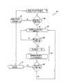
图3和4更详细地描述限制和改变程序18的操作。图3说明用于操作系统10的方法60的示范的实施方案。图4是显示系统10能够工作在自由冷却模式12的示范范围的图表。3 and 4 describe the operation of the limit and
当系统10工作在冷却模式14时,方法60包括第一温度比较步骤62。在第一温度比较步骤62期间,方法60确定外部环境空气40的温度52和工作流体46的离开温度54之间的差异ΔT是否足以让系统10切换到自由冷却模式12。如果ΔT是小于第一预定温度(显示为约6摄氏度(℃))系统10继续工作在冷却模式14。但是,如果ΔT是等于或大于第一预定的温度,方法60执行切换步骤64,以使系统10工作在自由冷却模式12。在切换步骤64后,方法60执行第二温度比较步骤66,以确定是否ΔT小于第二预定温度(显示为约10℃)。如果ΔT是等于或大于第二预定温度,系统10继续工作在自由冷却模式12。如果ΔT是小于第二预定温度,控制器16启动程序18以改变膨胀装置26的开口25的大小来保持在系统10到泵24的足够的压降和流速。When the system 10 is operating in the cooling mode 14 , the
因此,由于程序18的启动,方法60至少根据ΔT控制系统10来选择性限制通过膨胀装置26的流,以保持通过泵24的预定的压降。低于第一预定温度,方法60工作在冷却模式14。高于第二预定温度,方法60使系统10工作在不受限制的自由冷却模式12,即膨胀装置26在完全开放的位置。但是,在第一和第二预定温度之间,方法60工作在受限的或有限的自由冷却模式12,这样方法60在完全开放位置和基本关闭位置之间的任何地方以及其间的任何子范围改变膨胀装置26。Thus, as a result of initiation of routine 18 ,
方法60在启动程序18后继续工作在自由冷却模式12,并在某些实施方案中包括第三温度比较步骤68。非常像上面所讨论的第一比较步骤80,第三步比较步骤80判断如果ΔT是大于或等于第一预定温度,系统10继续工作在自由冷却模式12。但是,如果ΔT是小于第一预定温度,程序18在泵关闭步骤70将泵24切换到“关闭”状态,并且在冷却模式切换步骤90将系统10切换回冷却模式14。The
图6是说明工作范围74的图表,在该工作范围中系统10能工作在自由冷却模式12。在此,工作范围74包括不受限制部分74-1和受限制部分74-2的图表。图表的x轴以摄氏度来显示ΔT;图表的y轴将膨胀装置26的开口大小R显示为膨胀装置的开口大小占其完全开放状态R_全的百分比。FIG. 6 is a graph illustrating the operating range 74 within which the system 10 can operate in the
在说明的实施方案中,在自由冷却模式12的不受限制部分74-1期间,开口大小R是完全开放的(例如,100)。然而,在被部分关闭(例如,45)和完全开放(例如,100)之间由程序18变更开口大小R。如同所示,膨胀装置26的百分比开放的变化关于ΔT的变化是线性的。但是,由本发明可以预期,关于ΔT的改变,程序18以一种方式来控制膨胀装置26,即线性的、非线性的及其任何组合。In the illustrated embodiment, the opening size R is fully open (eg, 100) during the unrestricted portion 74 - 1 of the
本发明已确定,对于低值的ΔT,尤其在第一和第二预定温度之间,没有控制膨胀装置26的开口25,泵24并不理想地工作。在一些实施方案中,最低值的R(R_最小)可以是大约45,也就是说,为允许有足够的流速,膨胀设备26的开口25的最小尺寸是R_全的约45%。The inventors have determined that for low values of ΔT, especially between the first and second predetermined temperatures, the pump 24 does not work ideally without controlling the
程序18被配置为不断调整膨胀装置26的开口25的大小,以在系统10内保持理想的压降和保持流速以使Q3<Q2<Q1。当适当的压降和/或流速不能通过调整膨胀装置开口保持时,控制器16将系统10从自由冷却模式12切换至冷却模式14。
应当注意的是,术语“第一”、“第二”、“第三”、“较高的”、“较低的”等可在此被用于修饰各种元素。除非特别声明,这些修饰语对被修饰元素并不意味着的空间、次序、或等级。It should be noted that the terms "first", "second", "third", "higher", "lower", etc. may be used herein to modify various elements. Unless otherwise stated, these modifiers do not imply space, order, or hierarchy for the modified element.
虽然本发明已参考一个或多个示范的实施方案被描述,这将被本领域的技术人员理解,可能作出各种变化和可能用等同物来取代其中元素,而都没有离开本发明的范围。此外,按照该公开的教示而不背离其范围可能作出许多修改,以适应某一特定情况或材料。因此,其意图是,本发明不被局限于作为设想的最佳模式披露的特定实施方案,而在于该公开将包括落入附加的权利要求的范围内的所有实施方案。While the invention has been described with reference to one or more exemplary embodiments, it will be understood by those skilled in the art that various changes may be made and equivalents may be substituted for elements thereof without departing from the scope of the invention. In addition, many modifications may be made to adapt a particular situation or material to the teachings of the disclosure without departing from its scope. Therefore, it is intended that the invention not be limited to the particular embodiment disclosed as the best mode contemplated, but that this disclosure will include all embodiments falling within the scope of the appended claims.
Claims (12)
Applications Claiming Priority (1)
| Application Number | Priority Date | Filing Date | Title |
|---|---|---|---|
| PCT/US2006/048910WO2008076120A1 (en) | 2006-12-21 | 2006-12-21 | Free-cooling limitation control for air conditioning systems |
Publications (2)
| Publication Number | Publication Date |
|---|---|
| CN101611277A CN101611277A (en) | 2009-12-23 |
| CN101611277Btrue CN101611277B (en) | 2011-11-16 |
Family
ID=39536592
Family Applications (1)
| Application Number | Title | Priority Date | Filing Date |
|---|---|---|---|
| CN2006800569139AExpired - Fee RelatedCN101611277B (en) | 2006-12-21 | 2006-12-21 | Free-cooling limitation control for air conditioning systems |
Country Status (5)
| Country | Link |
|---|---|
| US (1) | US20100023166A1 (en) |
| EP (1) | EP2122276B1 (en) |
| CN (1) | CN101611277B (en) |
| ES (1) | ES2753371T3 (en) |
| WO (1) | WO2008076120A1 (en) |
Families Citing this family (21)
| Publication number | Priority date | Publication date | Assignee | Title |
|---|---|---|---|---|
| WO2008079138A1 (en)* | 2006-12-27 | 2008-07-03 | Carrier Corporation | Methods and systems for controlling an air conditioning system operating in free cooling mode |
| EP2102570B1 (en)* | 2006-12-28 | 2016-11-02 | Carrier Corporation | Methods and systems for controlling air conditioning systems having a cooling mode and a free-cooling mode |
| WO2009038552A1 (en)* | 2007-09-18 | 2009-03-26 | Carrier Corporation | Methods and systems for controlling integrated air conditioning systems |
| US9151521B2 (en)* | 2008-04-22 | 2015-10-06 | Hill Phoenix, Inc. | Free cooling cascade arrangement for refrigeration system |
| US7913506B2 (en)* | 2008-04-22 | 2011-03-29 | Hill Phoenix, Inc. | Free cooling cascade arrangement for refrigeration system |
| US9314742B2 (en) | 2010-03-31 | 2016-04-19 | Toyota Motor Engineering & Manufacturing North America, Inc. | Method and system for reverse osmosis predictive maintenance using normalization data |
| US8221628B2 (en) | 2010-04-08 | 2012-07-17 | Toyota Motor Engineering & Manufacturing North America, Inc. | Method and system to recover waste heat to preheat feed water for a reverse osmosis unit |
| US8505324B2 (en) | 2010-10-25 | 2013-08-13 | Toyota Motor Engineering & Manufacturing North America, Inc. | Independent free cooling system |
| US9038404B2 (en) | 2011-04-19 | 2015-05-26 | Liebert Corporation | High efficiency cooling system |
| US9845981B2 (en) | 2011-04-19 | 2017-12-19 | Liebert Corporation | Load estimator for control of vapor compression cooling system with pumped refrigerant economization |
| US9316424B2 (en) | 2011-04-19 | 2016-04-19 | Liebert Corporation | Multi-stage cooling system with tandem compressors and optimized control of sensible cooling and dehumidification |
| CN104040268B (en)* | 2012-02-22 | 2016-12-07 | 富士电机株式会社 | Integral air conditioner system and its control device |
| US9194615B2 (en) | 2013-04-05 | 2015-11-24 | Marc-Andre Lesmerises | CO2 cooling system and method for operating same |
| CA2928553C (en) | 2015-04-29 | 2023-09-26 | Marc-Andre Lesmerises | Co2 cooling system and method for operating same |
| US10254028B2 (en) | 2015-06-10 | 2019-04-09 | Vertiv Corporation | Cooling system with direct expansion and pumped refrigerant economization cooling |
| CN107850354A (en)* | 2015-07-22 | 2018-03-27 | 开利公司 | Liquid circulation system for combined free cooling and mechanical cooling |
| EP3608606A4 (en)* | 2017-04-04 | 2020-02-26 | Mitsubishi Electric Corporation | REFRIGERATION CIRCUIT DEVICE |
| EP3760951B1 (en) | 2019-07-05 | 2022-04-27 | Carrier Corporation | Air handling unit and method for controlling such an air handling unit |
| WO2022066663A1 (en)* | 2020-09-22 | 2022-03-31 | Johnson Controls Tyco IP Holdings LLP | Free cooling operation of a chiller |
| US11828508B2 (en)* | 2021-03-29 | 2023-11-28 | LGL France S.A.S. | Combined chiller and free cooling system for operation at high ambient temperature |
| US20230007815A1 (en)* | 2021-06-30 | 2023-01-05 | Nvidia Corporation | In-rack refrigerant distribution unit with pressure control system |
Citations (4)
| Publication number | Priority date | Publication date | Assignee | Title |
|---|---|---|---|---|
| CN1227334A (en)* | 1998-02-23 | 1999-09-01 | 三菱电机株式会社 | air conditioner |
| US5984198A (en)* | 1997-06-09 | 1999-11-16 | Lennox Manufacturing Inc. | Heat pump apparatus for heating liquid |
| US6385981B1 (en)* | 2000-03-16 | 2002-05-14 | Mobile Climate Control Industries Inc. | Capacity control of refrigeration systems |
| US6640561B2 (en)* | 2000-03-16 | 2003-11-04 | Rc Group S.P.A. | Chilling unit with “free-cooling”, designed to operate also with variable flow rate; system and process |
Family Cites Families (12)
| Publication number | Priority date | Publication date | Assignee | Title |
|---|---|---|---|---|
| US3744273A (en)* | 1972-03-27 | 1973-07-10 | Trane Co | Refrigeration apparatus and method of operating for powered and nonpowered cooling modes |
| JP2909187B2 (en)* | 1990-10-26 | 1999-06-23 | 株式会社東芝 | Air conditioner |
| US5749237A (en)* | 1993-09-28 | 1998-05-12 | Jdm, Ltd. | Refrigerant system flash gas suppressor with variable speed drive |
| SE505455C2 (en)* | 1993-12-22 | 1997-09-01 | Ericsson Telefon Ab L M | Cooling system for air with two parallel cooling circuits |
| US5632154A (en)* | 1995-02-28 | 1997-05-27 | American Standard Inc. | Feed forward control of expansion valve |
| SE9600395L (en)* | 1996-02-02 | 1997-08-03 | Ericsson Telefon Ab L M | Method and apparatus for arranging spare time for cooling systems |
| JP2000193327A (en)* | 1998-12-25 | 2000-07-14 | Mitsubishi Electric Corp | Air conditioner and control method of air conditioner |
| JP2001263835A (en)* | 2000-03-24 | 2001-09-26 | Mitsubishi Electric Corp | Air conditioner |
| CN2524147Y (en)* | 2001-12-20 | 2002-12-04 | 浙江盾安人工环境设备股份有限公司 | Energy-saving refrigeration cycling devices |
| US6871509B2 (en)* | 2002-10-02 | 2005-03-29 | Carrier Corporation | Enhanced cooling system |
| DE10354454B4 (en)* | 2003-11-21 | 2009-11-26 | Technotrans Ag | Temperature control device for printing machines |
| US7658079B2 (en)* | 2006-11-22 | 2010-02-09 | Bailey Peter F | Cooling system and method |
- 2006
- 2006-12-21CNCN2006800569139Apatent/CN101611277B/ennot_activeExpired - Fee Related
- 2006-12-21USUS12/520,831patent/US20100023166A1/ennot_activeAbandoned
- 2006-12-21ESES06845977Tpatent/ES2753371T3/enactiveActive
- 2006-12-21WOPCT/US2006/048910patent/WO2008076120A1/enactiveApplication Filing
- 2006-12-21EPEP06845977.5Apatent/EP2122276B1/ennot_activeNot-in-force
Patent Citations (4)
| Publication number | Priority date | Publication date | Assignee | Title |
|---|---|---|---|---|
| US5984198A (en)* | 1997-06-09 | 1999-11-16 | Lennox Manufacturing Inc. | Heat pump apparatus for heating liquid |
| CN1227334A (en)* | 1998-02-23 | 1999-09-01 | 三菱电机株式会社 | air conditioner |
| US6385981B1 (en)* | 2000-03-16 | 2002-05-14 | Mobile Climate Control Industries Inc. | Capacity control of refrigeration systems |
| US6640561B2 (en)* | 2000-03-16 | 2003-11-04 | Rc Group S.P.A. | Chilling unit with “free-cooling”, designed to operate also with variable flow rate; system and process |
Non-Patent Citations (2)
| Title |
|---|
| JP特开2006-57932A 2006.03.02 |
| 孙丽颖等.冷剂自然循环空调机的特性与应用.《哈尔滨商业大学学报(自然科学版)》.2004,第20卷(第6期),729-732.* |
Also Published As
| Publication number | Publication date |
|---|---|
| ES2753371T3 (en) | 2020-04-08 |
| HK1138360A1 (en) | 2010-08-20 |
| EP2122276A4 (en) | 2014-02-26 |
| EP2122276A1 (en) | 2009-11-25 |
| CN101611277A (en) | 2009-12-23 |
| WO2008076120A1 (en) | 2008-06-26 |
| EP2122276B1 (en) | 2019-10-30 |
| US20100023166A1 (en) | 2010-01-28 |
Similar Documents
| Publication | Publication Date | Title |
|---|---|---|
| CN101611277B (en) | Free-cooling limitation control for air conditioning systems | |
| CN101680699B (en) | Free Cooling Capacity Control of Air Conditioning Systems | |
| CN101688703B (en) | Air conditioning system and method with free cooling pump protection program | |
| US8117859B2 (en) | Methods and systems for controlling air conditioning systems having a cooling mode and a free-cooling mode | |
| CN101802512B (en) | Methods and systems for controlling integrated air conditioning systems | |
| EP1881277A1 (en) | Air conditioner | |
| JP6950191B2 (en) | Air conditioner | |
| EP2068098A1 (en) | Air conditioner | |
| JP5129237B2 (en) | Flow control device in refrigeration circuit, control method of refrigeration system, and refrigeration system | |
| JP5481838B2 (en) | Heat pump cycle equipment | |
| JP6155824B2 (en) | Air conditioner | |
| JP6543446B2 (en) | Heating system | |
| JPH09236332A (en) | Heat pump apparatus for air conditioning | |
| EP3798534B1 (en) | A heat pump | |
| KR20180135882A (en) | A heat pump having refrigerant storage means | |
| KR20190005475A (en) | A high performance heat pump having variable capacity refrigerant storage means | |
| JP2009008346A (en) | Refrigeration equipment | |
| US20240210084A1 (en) | Refrigeration system | |
| HK1138360B (en) | Free-cooling limitation control for air conditioning systems | |
| US20240247845A1 (en) | Heating, ventilation, and air-conditioning systems and methods with bypass line | |
| KR20050112233A (en) | An air conditioner for multi-step driving | |
| HK1142391A (en) | Free-cooling capacity control for air conditioning systems | |
| KR20190005471A (en) | A heat pump having variable capacity refrigerant storage means | |
| HK1138358B (en) | Method and system for controlling air conditioning system | |
| HK1138361A1 (en) | Methods and systems for controlling air conditioning systems having a cooling mode and a free-cooling mode |
Legal Events
| Date | Code | Title | Description |
|---|---|---|---|
| C06 | Publication | ||
| PB01 | Publication | ||
| C10 | Entry into substantive examination | ||
| SE01 | Entry into force of request for substantive examination | ||
| REG | Reference to a national code | Ref country code:HK Ref legal event code:DE Ref document number:1138360 Country of ref document:HK | |
| C14 | Grant of patent or utility model | ||
| GR01 | Patent grant | ||
| REG | Reference to a national code | Ref country code:HK Ref legal event code:GR Ref document number:1138360 Country of ref document:HK | |
| CF01 | Termination of patent right due to non-payment of annual fee | ||
| CF01 | Termination of patent right due to non-payment of annual fee | Granted publication date:20111116 |