CN101601080B - Method for driving electrophoretic displays using dielectrophoretic forces - Google Patents
Method for driving electrophoretic displays using dielectrophoretic forcesDownload PDFInfo
- Publication number
- CN101601080B CN101601080BCN2008800039521ACN200880003952ACN101601080BCN 101601080 BCN101601080 BCN 101601080BCN 2008800039521 ACN2008800039521 ACN 2008800039521ACN 200880003952 ACN200880003952 ACN 200880003952ACN 101601080 BCN101601080 BCN 101601080B
- Authority
- CN
- China
- Prior art keywords
- frequency
- electric field
- display
- dielectrophoretic
- electrophoretic
- Prior art date
- Legal status (The legal status is an assumption and is not a legal conclusion. Google has not performed a legal analysis and makes no representation as to the accuracy of the status listed.)
- Active
Links
Images


Classifications
- G—PHYSICS
- G09—EDUCATION; CRYPTOGRAPHY; DISPLAY; ADVERTISING; SEALS
- G09G—ARRANGEMENTS OR CIRCUITS FOR CONTROL OF INDICATING DEVICES USING STATIC MEANS TO PRESENT VARIABLE INFORMATION
- G09G3/00—Control arrangements or circuits, of interest only in connection with visual indicators other than cathode-ray tubes
- G09G3/20—Control arrangements or circuits, of interest only in connection with visual indicators other than cathode-ray tubes for presentation of an assembly of a number of characters, e.g. a page, by composing the assembly by combination of individual elements arranged in a matrix no fixed position being assigned to or needed to be assigned to the individual characters or partial characters
- G09G3/34—Control arrangements or circuits, of interest only in connection with visual indicators other than cathode-ray tubes for presentation of an assembly of a number of characters, e.g. a page, by composing the assembly by combination of individual elements arranged in a matrix no fixed position being assigned to or needed to be assigned to the individual characters or partial characters by control of light from an independent source
- G09G3/3433—Control arrangements or circuits, of interest only in connection with visual indicators other than cathode-ray tubes for presentation of an assembly of a number of characters, e.g. a page, by composing the assembly by combination of individual elements arranged in a matrix no fixed position being assigned to or needed to be assigned to the individual characters or partial characters by control of light from an independent source using light modulating elements actuated by an electric field and being other than liquid crystal devices and electrochromic devices
- G09G3/344—Control arrangements or circuits, of interest only in connection with visual indicators other than cathode-ray tubes for presentation of an assembly of a number of characters, e.g. a page, by composing the assembly by combination of individual elements arranged in a matrix no fixed position being assigned to or needed to be assigned to the individual characters or partial characters by control of light from an independent source using light modulating elements actuated by an electric field and being other than liquid crystal devices and electrochromic devices based on particles moving in a fluid or in a gas, e.g. electrophoretic devices
- G—PHYSICS
- G02—OPTICS
- G02F—OPTICAL DEVICES OR ARRANGEMENTS FOR THE CONTROL OF LIGHT BY MODIFICATION OF THE OPTICAL PROPERTIES OF THE MEDIA OF THE ELEMENTS INVOLVED THEREIN; NON-LINEAR OPTICS; FREQUENCY-CHANGING OF LIGHT; OPTICAL LOGIC ELEMENTS; OPTICAL ANALOGUE/DIGITAL CONVERTERS
- G02F1/00—Devices or arrangements for the control of the intensity, colour, phase, polarisation or direction of light arriving from an independent light source, e.g. switching, gating or modulating; Non-linear optics
- G02F1/01—Devices or arrangements for the control of the intensity, colour, phase, polarisation or direction of light arriving from an independent light source, e.g. switching, gating or modulating; Non-linear optics for the control of the intensity, phase, polarisation or colour
- G02F1/13—Devices or arrangements for the control of the intensity, colour, phase, polarisation or direction of light arriving from an independent light source, e.g. switching, gating or modulating; Non-linear optics for the control of the intensity, phase, polarisation or colour based on liquid crystals, e.g. single liquid crystal display cells
- G02F1/133—Constructional arrangements; Operation of liquid crystal cells; Circuit arrangements
- G02F1/13306—Circuit arrangements or driving methods for the control of single liquid crystal cells
- G—PHYSICS
- G02—OPTICS
- G02F—OPTICAL DEVICES OR ARRANGEMENTS FOR THE CONTROL OF LIGHT BY MODIFICATION OF THE OPTICAL PROPERTIES OF THE MEDIA OF THE ELEMENTS INVOLVED THEREIN; NON-LINEAR OPTICS; FREQUENCY-CHANGING OF LIGHT; OPTICAL LOGIC ELEMENTS; OPTICAL ANALOGUE/DIGITAL CONVERTERS
- G02F1/00—Devices or arrangements for the control of the intensity, colour, phase, polarisation or direction of light arriving from an independent light source, e.g. switching, gating or modulating; Non-linear optics
- G02F1/01—Devices or arrangements for the control of the intensity, colour, phase, polarisation or direction of light arriving from an independent light source, e.g. switching, gating or modulating; Non-linear optics for the control of the intensity, phase, polarisation or colour
- G02F1/13—Devices or arrangements for the control of the intensity, colour, phase, polarisation or direction of light arriving from an independent light source, e.g. switching, gating or modulating; Non-linear optics for the control of the intensity, phase, polarisation or colour based on liquid crystals, e.g. single liquid crystal display cells
- G02F1/133—Constructional arrangements; Operation of liquid crystal cells; Circuit arrangements
- G02F1/1333—Constructional arrangements; Manufacturing methods
- G02F1/1345—Conductors connecting electrodes to cell terminals
- G—PHYSICS
- G02—OPTICS
- G02F—OPTICAL DEVICES OR ARRANGEMENTS FOR THE CONTROL OF LIGHT BY MODIFICATION OF THE OPTICAL PROPERTIES OF THE MEDIA OF THE ELEMENTS INVOLVED THEREIN; NON-LINEAR OPTICS; FREQUENCY-CHANGING OF LIGHT; OPTICAL LOGIC ELEMENTS; OPTICAL ANALOGUE/DIGITAL CONVERTERS
- G02F1/00—Devices or arrangements for the control of the intensity, colour, phase, polarisation or direction of light arriving from an independent light source, e.g. switching, gating or modulating; Non-linear optics
- G02F1/01—Devices or arrangements for the control of the intensity, colour, phase, polarisation or direction of light arriving from an independent light source, e.g. switching, gating or modulating; Non-linear optics for the control of the intensity, phase, polarisation or colour
- G02F1/165—Devices or arrangements for the control of the intensity, colour, phase, polarisation or direction of light arriving from an independent light source, e.g. switching, gating or modulating; Non-linear optics for the control of the intensity, phase, polarisation or colour based on translational movement of particles in a fluid under the influence of an applied field
- G02F1/166—Devices or arrangements for the control of the intensity, colour, phase, polarisation or direction of light arriving from an independent light source, e.g. switching, gating or modulating; Non-linear optics for the control of the intensity, phase, polarisation or colour based on translational movement of particles in a fluid under the influence of an applied field characterised by the electro-optical or magneto-optical effect
- G02F1/167—Devices or arrangements for the control of the intensity, colour, phase, polarisation or direction of light arriving from an independent light source, e.g. switching, gating or modulating; Non-linear optics for the control of the intensity, phase, polarisation or colour based on translational movement of particles in a fluid under the influence of an applied field characterised by the electro-optical or magneto-optical effect by electrophoresis
- G—PHYSICS
- G09—EDUCATION; CRYPTOGRAPHY; DISPLAY; ADVERTISING; SEALS
- G09G—ARRANGEMENTS OR CIRCUITS FOR CONTROL OF INDICATING DEVICES USING STATIC MEANS TO PRESENT VARIABLE INFORMATION
- G09G3/00—Control arrangements or circuits, of interest only in connection with visual indicators other than cathode-ray tubes
- G09G3/20—Control arrangements or circuits, of interest only in connection with visual indicators other than cathode-ray tubes for presentation of an assembly of a number of characters, e.g. a page, by composing the assembly by combination of individual elements arranged in a matrix no fixed position being assigned to or needed to be assigned to the individual characters or partial characters
- G09G3/2007—Display of intermediate tones
- G—PHYSICS
- G02—OPTICS
- G02F—OPTICAL DEVICES OR ARRANGEMENTS FOR THE CONTROL OF LIGHT BY MODIFICATION OF THE OPTICAL PROPERTIES OF THE MEDIA OF THE ELEMENTS INVOLVED THEREIN; NON-LINEAR OPTICS; FREQUENCY-CHANGING OF LIGHT; OPTICAL LOGIC ELEMENTS; OPTICAL ANALOGUE/DIGITAL CONVERTERS
- G02F1/00—Devices or arrangements for the control of the intensity, colour, phase, polarisation or direction of light arriving from an independent light source, e.g. switching, gating or modulating; Non-linear optics
- G02F1/01—Devices or arrangements for the control of the intensity, colour, phase, polarisation or direction of light arriving from an independent light source, e.g. switching, gating or modulating; Non-linear optics for the control of the intensity, phase, polarisation or colour
- G02F1/165—Devices or arrangements for the control of the intensity, colour, phase, polarisation or direction of light arriving from an independent light source, e.g. switching, gating or modulating; Non-linear optics for the control of the intensity, phase, polarisation or colour based on translational movement of particles in a fluid under the influence of an applied field
- G02F1/1675—Constructional details
- G02F1/1676—Electrodes
- G—PHYSICS
- G02—OPTICS
- G02F—OPTICAL DEVICES OR ARRANGEMENTS FOR THE CONTROL OF LIGHT BY MODIFICATION OF THE OPTICAL PROPERTIES OF THE MEDIA OF THE ELEMENTS INVOLVED THEREIN; NON-LINEAR OPTICS; FREQUENCY-CHANGING OF LIGHT; OPTICAL LOGIC ELEMENTS; OPTICAL ANALOGUE/DIGITAL CONVERTERS
- G02F2202/00—Materials and properties
- G02F2202/42—Materials having a particular dielectric constant
- G—PHYSICS
- G09—EDUCATION; CRYPTOGRAPHY; DISPLAY; ADVERTISING; SEALS
- G09G—ARRANGEMENTS OR CIRCUITS FOR CONTROL OF INDICATING DEVICES USING STATIC MEANS TO PRESENT VARIABLE INFORMATION
- G09G2310/00—Command of the display device
- G09G2310/06—Details of flat display driving waveforms
- G—PHYSICS
- G09—EDUCATION; CRYPTOGRAPHY; DISPLAY; ADVERTISING; SEALS
- G09G—ARRANGEMENTS OR CIRCUITS FOR CONTROL OF INDICATING DEVICES USING STATIC MEANS TO PRESENT VARIABLE INFORMATION
- G09G2320/00—Control of display operating conditions
- G09G2320/02—Improving the quality of display appearance
- G09G2320/0223—Compensation for problems related to R-C delay and attenuation in electrodes of matrix panels, e.g. in gate electrodes or on-substrate video signal electrodes
- G—PHYSICS
- G09—EDUCATION; CRYPTOGRAPHY; DISPLAY; ADVERTISING; SEALS
- G09G—ARRANGEMENTS OR CIRCUITS FOR CONTROL OF INDICATING DEVICES USING STATIC MEANS TO PRESENT VARIABLE INFORMATION
- G09G2320/00—Control of display operating conditions
- G09G2320/02—Improving the quality of display appearance
- G09G2320/0247—Flicker reduction other than flicker reduction circuits used for single beam cathode-ray tubes
Landscapes
- Physics & Mathematics (AREA)
- Nonlinear Science (AREA)
- General Physics & Mathematics (AREA)
- Engineering & Computer Science (AREA)
- Chemical & Material Sciences (AREA)
- Optics & Photonics (AREA)
- Theoretical Computer Science (AREA)
- Computer Hardware Design (AREA)
- Mathematical Physics (AREA)
- Crystallography & Structural Chemistry (AREA)
- Life Sciences & Earth Sciences (AREA)
- Chemical Kinetics & Catalysis (AREA)
- Electrochemistry (AREA)
- Molecular Biology (AREA)
- Health & Medical Sciences (AREA)
- Electrochromic Elements, Electrophoresis, Or Variable Reflection Or Absorption Elements (AREA)
- Control Of Indicators Other Than Cathode Ray Tubes (AREA)
Abstract
Description
Translated fromChinese本申请涉及:(a)美国专利No.7,116,466;(b)美国专利公开No.2006/0038772;(c)美国专利公开No.2005/0213191;(b)美国专利No.7,259,744;和(c)美国专利No.7,193,625。This application is related to: (a) U.S. Patent No. 7,116,466; (b) U.S. Patent Publication No. 2006/0038772; (c) U.S. Patent Publication No. 2005/0213191; (b) U.S. Patent No. 7,259,744; and (c) US Patent No. 7,193,625.
本发明涉及用于使用介电泳力驱动电泳显示器的方法。更具体地,本发明涉及用于使用电泳和介电泳力在不同光学状态之间转换基于粒子的电泳显示器的驱动方法。本发明的显示器可以是快门模式显示器(如在下面被限定的该术语)或者是光调制器,也就是指可变透射窗口、反射镜和被设计成调制通过其中的光或其它电磁辐射的量的类似设备;为了方便,这里一般地使用术语“光”,但是该术语应该在广义被理解为包括在非可见波长的电磁辐射。例如,如下面所提到的,可以应用本发明来提供可以调制红外辐射的窗口用于控制建筑物中的温度。更具体地,本发明涉及使用基于粒子的电泳媒质来控制光调制的电光显示器和光调制器。The present invention relates to methods for driving electrophoretic displays using dielectrophoretic forces. More specifically, the present invention relates to driving methods for switching particle-based electrophoretic displays between different optical states using electrophoretic and dielectrophoretic forces. The displays of the present invention may be shutter mode displays (as that term is defined below) or light modulators, that is to say variable transmission windows, mirrors and devices designed to modulate the amount of light or other electromagnetic radiation passing therethrough for convenience, the term "light" is used generally herein, but the term should be construed broadly to include electromagnetic radiation at non-visible wavelengths. For example, as mentioned below, the invention can be applied to provide windows that can modulate infrared radiation for controlling temperature in buildings. More specifically, the present invention relates to electro-optic displays and light modulators that use particle-based electrophoretic media to control light modulation.
在这里以成像领域中的常规含义使用术语“灰态”,以指示介于像素的两个极端光学状态的中间的状态,并且不一定是暗示在这两个极端光学状态之间的黑白转变。例如,下面提及的数个专利和公开的申请描述极端状态是白和深蓝的电泳显示器,使得中间的“灰态”实际上是淡蓝。实际上,两个极端状态之间的转变可以根本不是颜色的改变,而是显示器的一些其它光学特性的改变,例如光学透射、反射、荧光或者旨用于机器阅读的显示器的情况下,可以是在可视范围外的电磁波长在反射改变意义下的伪彩色。The term "gray state" is used here in its conventional sense in the imaging arts to indicate a state intermediate between two extreme optical states of a pixel, and not necessarily to imply a black-and-white transition between these two extreme optical states. For example, several of the patents and published applications mentioned below describe electrophoretic displays in which the extreme states are white and dark blue, such that the intermediate "gray state" is actually light blue. In fact, the transition between the two extreme states may not be a change of color at all, but a change of some other optical property of the display, such as optical transmission, reflection, fluorescence or in the case of a display intended for machine reading, may be False coloring in the sense of a change in reflection at electromagnetic wavelengths outside the visible range.
在这里以本领域中的常规含义使用术语“双稳定的”和“双稳定性”,以指示包括具有第一和第二显示状态的显示元件的显示器,所述第一和第二显示状态至少有一种光学性质不同,使得任何给定元件通过具有有限持续时间的寻址脉冲被驱动成呈现其第一或第二显示状态后,在寻址脉冲终止后,该状态将持续至少是改变该显示元件的状态所需寻址脉冲的最小持续时间的几倍时间,例如至少是四倍时间。在美国专利No.7,170,670中示出:一些基于粒子的能够显示灰度级的电泳显示器不仅在其极端的黑和白状态下稳定,而且在其中间的灰态下也稳定,对于其它一些类型的电光显示器同样如此。这种类型的显示器被恰当地称为“多稳态”而不是双稳态,但是为了方便起见这里使用的术语“双稳态”覆盖双稳态和多稳态显示器。The terms "bi-stable" and "bi-stable" are used herein in their conventional meaning in the art to denote a display that includes a display element having a first and a second display state that is at least have a different optical property such that after any given element is driven to assume its first or second display state by an addressing pulse of finite duration, that state will persist for at least the change in the display state after the termination of the addressing pulse The state of the element requires several times, for example at least four times, the minimum duration of the addressing pulse. In U.S. Patent No. 7,170,670 it is shown that some particle-based electrophoretic displays capable of displaying grayscale are stable not only in their extreme black and white states, but also in their intermediate gray states, and for some other types of The same goes for electro-optic displays. This type of display is properly called "multistable" rather than bistable, but for convenience the term "bistable" is used here to cover both bistable and multistable displays.
在这里以其传统含义使用术语“脉冲”,以指示电压相对于时间的积分。然而,一些双稳态电光媒质用作为电荷换能器,并且对于这些媒质可以使用脉冲的可选定义,即电流对时间的积分(等于所施加的总电荷)。根据媒质是否用作电压-时间脉冲换能器或电荷脉冲换能器,应该使用脉冲合适的定义。The term "pulse" is used here in its traditional sense to indicate the integration of voltage with respect to time. However, some bistable electro-optic media act as charge transducers, and an alternative definition of pulse, ie the integral of current over time (equal to the total applied charge), can be used for these media. Depending on whether the medium is used as a voltage-time pulse transducer or a charge pulse transducer, the appropriate definition of pulse should be used.
数年来被大量研究和开发的是基于粒子的电泳显示器,其中多个带电粒子在电场的影响下穿过流体。与液晶显示器相比较,电泳显示器的优点在于具有良好的亮度和对比度、宽视角、状态双稳定性以及低功耗。然而,这些显示器的长期图像质量问题妨碍了它们的广泛使用。例如,构成电泳显示器的粒子趋向于沉降,导致这些显示器的使用寿命不够。Much researched and developed over the years are particle-based electrophoretic displays, in which multiple charged particles pass through a fluid under the influence of an electric field. Compared with liquid crystal displays, electrophoretic displays have the advantages of good brightness and contrast, wide viewing angles, state bistability, and low power consumption. However, long-term image quality issues with these displays have prevented their widespread use. For example, the particles that make up electrophoretic displays tend to settle, resulting in insufficient lifetime of these displays.
如上所述,电泳媒质中需要存在流体。在大部分现有技术的电泳媒质中这种流体是指液体,但是电泳媒质可以用气态的流体制成;参见诸如Kitamura,T.等人的“在电子纸类显示器中电子色粉的运动”(″Electricaltoner movement for electronic paper-like display″),IDW日本,2001,Paper HCS1-1和Yamaguchi,Y.等人的“利用带静电的绝缘粒子的色粉显示器”(″Toner display using insulative particles chargedtriboelectrically″),IDW日本,2001,Paper AMD4-4。同时参见美国专利公开No.2005/0001810;欧洲专利申请1,462,847、1,482,354、1,484,635、1,500,971、1,501,194、1,536,271、1,542,067、1,577,702、1,577,703和1,598,694;以及国际申请WO 2004/090626、WO2004/079442和WO2004/001498。这种基于气体的电泳媒质容易遇到跟基于液体的电泳媒质同种类型的由于粒子沉降带来的问题,当媒质用于允许存在这种沉降的方向时,例如用于标牌,其中媒质位于在一个垂直的平板上。事实上,在基于气体的电泳媒质中粒子沉降问题比基于液体的电泳媒质中似乎更严重,这是因为与液态流体相比气态悬浮流体的粘性更低,这使得电泳粒子沉降得更快。As mentioned above, the presence of fluid is required in the electrophoretic medium. In most prior art electrophoretic media this fluid is referred to as a liquid, but electrophoretic media can be made of gaseous fluids; see eg "Movement of Electronic Toner in Electronic Paper Displays" by Kitamura, T. et al. ("Electrical toner movement for electronic paper-like display"), IDW Japan, 2001, Paper HCS1-1 and Yamaguchi, Y. et al.'s "Toner display using insulating particles charged triboelectrically" ″), IDW Japan, 2001, Paper AMD4-4.同时参见美国专利公开No.2005/0001810;欧洲专利申请1,462,847、1,482,354、1,484,635、1,500,971、1,501,194、1,536,271、1,542,067、1,577,702、1,577,703和1,598,694;以及国际申请WO 2004/090626、WO2004/079442和WO2004/001498。 Such gas-based electrophoretic media are susceptible to the same type of problems due to particle settling as liquid-based electrophoretic media when the media is used in an orientation that allows such settling, such as for signage, where the media is located at on a vertical plate. In fact, the problem of particle settling seems to be more severe in gas-based electrophoretic media than in liquid-based electrophoretic media because the lower viscosity of gaseous suspension fluids compared to liquid fluids allows electrophoretic particles to settle faster.
转让给麻省理工学院(MIT)和伊英克(E Ink)公司的或在这二者名下的大量专利和申请最近已经公布,它们描述了封装的电泳媒质。这种封装的媒质包括大量的小囊,其中每一个小囊本身包含内相以及环绕内相的囊壁,其中所述内相含有悬浮在液体悬浮媒质中的可电泳运动的粒子。典型地,这些囊本身保存在聚合粘合剂中以形成位于两个电极之间的粘附层。例如,在美国专利No.5,930,026;5,961,804;6,017,584;6,067,185;6,118,426;6,120,588;6,120,839;6,124,851;6,130,773;6,130,774;6,172,798;6,177,921;6,232,950;6,249,271;6,252,564;6,262,706;6,262,833;6,300,932;6,312,304;6,312,971;6,323,989;6,327,072;6,376,828;6,377,387;6,392,785;6,392,786;6,413,790;6,422,687;6,445,374;6,445,489;6,459,418;6,473,072;6,480,182;6,498,114;6,504,524;6,506,438;6,512,354;6,515,649;6,518,949;6,521,489;6,531,997;6,535,197;6,538,801;6,545,291;6,580,545;6,639,578;6,652,075;6,657,772;6,664,944;6,680,725;6,683,333;6,704,133;6,710,540;6,721,083;6,724,519;6,727,881;6,738,050;6,750,473;6,753,999;6,816,147;6,819,471;6,822,782;6,825,068;6,825,829;6,825,970;6,831,769;6,839,158;6,842,167;6,842,279;6,842,657;6,864,875;6,865,010;6,866,760;6,870,661;6,900,851;6,922,276;6,950,200;6,958,848;6,967,640;6,982,178;6,987,603;6,995,550;7,002,728;7,012,600;7,012,735;7,023,420;7,030,412;7,030,854;7,034,783;7,038,655;7,061,663;7,071,913;7,075,502;7,075,703;7,079,305;7,106,296;7,109,968;7,110,163;7,110,164;7,116,318;7,116,466;7,119,759;7,119,772;7,148,128;7,167,155;7,170,670;7,173,752;7,176,880;7,180,649;7,190,008;7,193,625;7,202,847;7,202,991;7,206,119;7,223,672;7,230,750;7,230,751;7,236,790;和7,236,792;以及美国专利申请公开No.2002/0060321;2002/0090980;2003/0011560;2003/0102858;2003/0151702;2003/0222315;2004/0094422;2004/0105036;2004/0112750;2004/0119681;2004/0136048;2004/0155857;2004/0180476;2004/0190114;2004/0196215;2004/0226820;2004/0257635;2004/0263947;2005/0000813;2005/0007336;2005/0012980;2005/0017944;2005/0018273;2005/0024353;2005/0062714;2005/0067656;2005/0099672;2005/0122284;2005/0122306;2005/0122563;2005/0134554;2005/0151709;2005/0152018;2005/0156340;2005/0179642;2005/0190137;2005/0212747;2005/0213191;2005/0219184;2005/0253777;2005/0280626;2006/0007527;2006/0024437;2006/0038772;2006/0139308;2006/0139310;2006/0139311;2006/0176267;2006/0181492;2006/0181504;2006/0194619;2006/0197736;2006/0197737;2006/0197738;2006/0202949;2006/0223282;2006/0232531;2006/0245038;2006/0256425;2006/0262060;2006/0279527;2006/0291034;2007/0035532;2007/0035808;2007/0052757;2007/0057908;2007/0069247;2007/0085818;2007/0091417;2007/0091418;2007/0097489;2007/0109219;2007/0128352;和2007/0146310;以及国际申请公开No.WO 00/38000;WO 00/36560;WO 00/67110;和WO 01/07961;以及欧洲专利No.1,099,207B1;和1,145,072B1中均描述了这种类型的封装的媒质。Numerous patents and applications assigned to or in the name of MIT and E Ink Corporation have recently been published and describe encapsulated electrophoretic media. Such encapsulated media comprise a plurality of vesicles, each of which itself contains an inner phase containing electrophoretically movable particles suspended in a liquid suspending medium, and a wall surrounding the inner phase. Typically, the sacs themselves are held in a polymeric binder to form an adhesive layer between the two electrodes.例如,在美国专利No.5,930,026;5,961,804;6,017,584;6,067,185;6,118,426;6,120,588;6,120,839;6,124,851;6,130,773;6,130,774;6,172,798;6,177,921;6,232,950;6,249,271;6,252,564;6,262,706;6,262,833;6,300,932;6,312,304;6,312,971;6,323,989;6,327,072 ;6,376,828;6,377,387;6,392,785;6,392,786;6,413,790;6,422,687;6,445,374;6,445,489;6,459,418;6,473,072;6,480,182;6,498,114;6,504,524;6,506,438;6,512,354;6,515,649;6,518,949;6,521,489;6,531,997;6,535,197;6,538,801;6,545,291;6,580,545;6,639,578;6,652,075 ;6,657,772;6,664,944;6,680,725;6,683,333;6,704,133;6,710,540;6,721,083;6,724,519;6,727,881;6,738,050;6,750,473;6,753,999;6,816,147;6,819,471;6,822,782;6,825,068;6,825,829;6,825,970;6,831,769;6,839,158;6,842,167;6,842,279;6,842,657;6,864,875;6,865,010 ;6,866,760;6,870,661;6,900,851;6,922,276;6,950,200;6,958,848;6,967,640;6,982,178;6,987,603;6,995,550;7,002,728;7,012,600;7,012,735;7,023,420;7,030,412;7,030,854;7,034,783;7,038,655;7,061,663;7,071,913;7,075,502;7,075,703;7,079,305;7,106,296;7,109,968 ;7,110,163;7,110,164 ;7,116,318;7,116,466;7,119,759;7,119,772;7,148,128;7,167,155;7,170,670;7,173,752;7,176,880;7,180,649;7,190,008;7,193,625;7,202,847;7,202,991;7,206,119;7,223,672;7,230,750;7,230,751;7,236,790;和7,236,792;以及美国专利申请公开No.2002 /0060321; 2002/0090980; 2003/0011560; 2003/0102858; 2003/0151702; 2003/0222315; 2004/0094422; 2004/0105036; 2004/0112750; 2004/0119681; 2004/0136048; 2004/0155857; 2004/0180470470470470470470470470470470470470470470470470470470470470470470470470470470470470477 ;2004/0190114;2004/0196215;2004/0226820;2004/0257635;2004/0263947;2005/0000813;2005/0007336;2005/0012980;2005/0017944;2005/0018273;2005/0024353;2005/0062714;2005 /0067656; 2005/0099672; 2005/0122284; 2005/0122306; 2005/0122563; 2005/0134554; 2005/0151709; 2005/0152018; 2005/0156340; 2005/0179642; 2005/0190137; 2005/021313131313131313131313131313131313131313131313131313131313131313131313131313131313131313131 ;2005/0219184;2005/0253777;2005/0280626;2006/0007527;2006/0024437;2006/0038772;2006/0139308;2006/0139310;2006/0139311;2006/0176267;2006/0181492;2006/0181504;2006 /0194619; 2006/0197736; 2006/0197737; 2006/0197738; 2006/0202949; 2006/0223282; 0279527; 2006/021034; 2007/0035532; 2007/0035808; 2007/0052757; 2007/0057908; 2007/0069247; 2007/0085818; 2007/0091417; 2007/0091418; 2007/0097489; 2007/0109219; 2007/0128352; and 2007/0146310; and International Application Publication Nos. WO 00/38000; WO 00/36560; WO 00/67110; and WO 01/07961; and European Patent Nos. 1,099,207B1; and 1,145,072B1. The packaged medium.
已知的封装的和未封装的电泳媒质可以分成两个主要类型,这里为了方便分别称为“单粒子”和“双粒子”。两种类型的完整描述可以在国际申请公开No.WO 02/093245中找到。实质上,单粒子媒质只有悬浮在悬浮媒质中的单一类型的电泳粒子,其至少一个光学特性与粒子的光学特性不同,而双粒子媒质具有至少一个光学特性不同的两个不同类型的粒子和无色或有色(典型地为无色)的悬浮流体。两种类型的粒子在电泳活动性方面不同。单和双粒子电泳显示器都能够具有介于显示器的两个极端光学状态中间的光学特性的中间灰态。Known encapsulated and unencapsulated electrophoretic media can be divided into two main types, referred to herein for convenience as "single particle" and "dual particle", respectively. A complete description of both types can be found in International Application Publication No. WO 02/093245. In essence, single-particle media have only a single type of electrophoretic particles suspended in the suspension medium with at least one optical property different from that of the particle, while dual-particle media have two different types of particles that differ in at least one optical property and no Colored or colored (typically colorless) suspending fluid. The two types of particles differ in their electrophoretic mobility. Both single and dual particle electrophoretic displays are capable of intermediate gray states with optical properties intermediate between the two extreme optical states of the display.
上述许多专利和申请认识到在封装的电泳媒质中的围绕分离微囊的壁可以用连续相代替,因而产生所谓的“聚合物分散的电泳显示器”,其中电泳媒质包括多个电泳流体的分离的小滴以及聚合物材料的连续相,并且即使分离的囊膜不与每个单独的小滴相关,但在这样聚合物分散的电泳显示器内的电泳流体的分离小滴也可以被认为是囊或微囊;参见诸如前述的美国专利No.6,866,760。因此,为了本申请的目的,这种聚合物分散的电泳媒质被认为是封装的电泳媒质的子类。Many of the aforementioned patents and applications recognize that the walls surrounding the separate microcapsules in encapsulated electrophoretic media can be replaced by a continuous phase, thus resulting in so-called "polymer dispersed electrophoretic displays" in which the electrophoretic media includes multiple separate layers of electrophoretic fluid. droplets as well as the continuous phase of polymeric material, and even though the separate capsules are not associated with each individual droplet, the separated droplets of electrophoretic fluid within such polymer dispersed electrophoretic displays can be considered capsules or Microcapsules; see, eg, the aforementioned US Patent No. 6,866,760. Thus, for the purposes of this application, such polymer dispersed electrophoretic media are considered a subclass of encapsulated electrophoretic media.
一种相关类型的电泳显示器是所谓的“微单元电泳显示器”。在微单元电泳显示器中,带电粒子和流体不是封装在微囊中而是保持在形成于载体媒质(通常是聚合物膜)内的多个腔内。参见诸如美国专利No.6,672,921和6,788,449,其均转让给Sipix Imaging公司。A related type of electrophoretic display is the so-called "microcell electrophoretic display". In microcellular electrophoretic displays, charged particles and fluids are not encapsulated in microcapsules but are held within cavities formed within a carrier medium, usually a polymer film. See, eg, US Patent Nos. 6,672,921 and 6,788,449, both assigned to Sipix Imaging Corporation.
虽然电泳媒质通常是不透明的(因为,例如在很多电泳媒质中粒子基本阻挡通过显示器的可见光的透射)并且在反射模式下工作,许多电泳显示器可以制成在所谓的“快门模式”下工作,在该模式下一种显示状态基本是不透明的而一种显示状态是透光的。参见诸如前述的美国专利No.6,130,774和6,172,798,以及美国专利No.5,872,552、6,144,361、6,271,823、6,225,971和6,184,856。类似于电泳显示器,但是依赖于电场强度变化的介电泳显示器也可以在类似的模式下工作;参见美国专利No.4,418,346。其它类型的电光显示器也能够在快门模式下工作。Although electrophoretic media are generally opaque (because, for example, the particles in many electrophoretic media substantially block the transmission of visible light through the display) and operate in a reflective mode, many electrophoretic displays can be made to operate in a so-called "shutter mode", where In this mode, one display state is substantially opaque and one display state is light-transmissive. See, for example, the aforementioned US Patent Nos. 6,130,774 and 6,172,798, and US Patent Nos. 5,872,552, 6,144,361, 6,271,823, 6,225,971 and 6,184,856. Dielectrophoretic displays, which are similar to electrophoretic displays but rely on changes in electric field strength, can also operate in a similar mode; see US Patent No. 4,418,346. Other types of electro-optic displays are also capable of operating in shutter mode.
封装的电泳显示器通常不遭受传统电泳设备的聚集和沉淀失效模式,并且提供了另外的优点,例如能够将显示器印制或涂覆在各种柔性和刚性基底上。(使用词语“印制”意在包括但不限于下列所有印刷和涂覆形式:诸如斑块压型涂覆(patch die coating)的预先计量式(pre-metered)涂覆、狭缝式或挤压式涂覆、坡流式或阶式(cascade)涂覆、帘式涂覆;诸如辊式刮刀(knife over roll)涂覆、向前和反向辊涂覆的压辊涂覆;照相凹板式涂覆;浸渍涂覆;喷涂;弯月面(meniscus)涂覆;旋涂;刷涂;气刀涂覆;丝网印刷工艺;静电印刷工艺;热印刷工艺、喷墨印刷工艺;电泳沉积(参见美国专利公开No.2004/0226820)以及其它类似技术)。因此,所得到的显示器可以是柔性的。此外,由于显示媒质可以(使用各种方法)被印制,显示器本身可以廉价地制造。Encapsulated electrophoretic displays generally do not suffer from the aggregation and precipitation failure modes of conventional electrophoretic devices and offer additional advantages such as the ability to print or coat displays on a variety of flexible and rigid substrates. (Use of the word "printing" is intended to include, but not be limited to, all forms of printing and coating: pre-metered coating such as patch die coating, slot or extrusion Pressure coating, slide or cascade coating, curtain coating; pressure roll coating such as knife over roll coating, forward and reverse roll coating; photographic gravure Sheet coating; dip coating; spray coating; meniscus coating; spin coating; brush coating; air knife coating; screen printing process; electrostatic printing process; thermal printing process, inkjet printing process; electrophoretic deposition (see US Patent Publication No. 2004/0226820) and other similar techniques). Therefore, the resulting display can be flexible. Furthermore, since the display medium can be printed (using various methods), the display itself can be manufactured inexpensively.
快门模式显示器的一种潜在的重要应用是作为光调制器,也就是指可变透射窗口、反射镜和被设计用于调制通过其中的光或其它电磁辐射的量的类似设备。例如,本发明可以应用于提供调制红外辐射的窗口用于控制建筑物中的温度。One potentially important application of shutter-mode displays is as light modulators, that is, variable transmission windows, mirrors, and similar devices designed to modulate the amount of light or other electromagnetic radiation passing through them. For example, the invention may be applied to provide windows that modulate infrared radiation for controlling temperature in buildings.
如在前述的2005/0213191中所讨论的,电泳媒质一种潜在的重要市场是具有可变光透射的窗口。由于建筑和汽车的能源性能变得日渐重要,电泳媒质能够被用作在窗口上的涂层以使得通过窗口透射的入射辐射的比例能够通过改变电泳媒质的光学状态来电子控制。这种电子控制能够取代由通过诸如使用窗帘的入射辐射的“机械”控制。期望在建筑中的这种电子“可变透射”(“VT”)技术的有效实施以提供(1)在炎热天气中的不期望的热效应的减少,从而减少需要用于冷却的能量的量、空调设备的大小和峰值电需求;(2)自然光的增加使用,从而减少需要用于照明的能量和峰值电需求;以及(3)通过增加热和视觉舒适度来提高的居住者的舒适度。甚至期望在机动车上产生更大的益处,在机动车中抛光表面与所封闭的体积的比率明显比普通建筑物大。尤其是,期望在机动车中VT技术的有效实行不仅提供前述的益处,还提供(1)增加的驾驶安全性,(2)减少的眩光,(3)增强的反射镜性能(通过在反射镜上使用电光涂层),和(4)增加的使用平视显示器的能力。包括VT技术的其它潜在的应用包括调光玻璃(privacy glass)和在电子设备中的眩光防护。As discussed in the aforementioned 2005/0213191, one potentially important market for electrophoretic media is windows with variable light transmission. As the energy performance of buildings and automobiles becomes increasingly important, electrophoretic media can be used as coatings on windows so that the proportion of incident radiation transmitted through the window can be controlled electronically by changing the optical state of the electrophoretic media. This electronic control can replace "mechanical" control by incident radiation, such as through the use of curtains. Efficient implementation of such electronic "variable transmission" ("VT") technology in buildings is desired to provide (1) a reduction in undesired thermal effects in hot weather, thereby reducing the amount of energy required for cooling, Size and peak electrical demand of air conditioning equipment; (2) increased use of natural light, thereby reducing energy and peak electrical demand needed for lighting; and (3) improved occupant comfort through increased thermal and visual comfort. Even greater benefits are expected to arise in motor vehicles, where the ratio of polished surface to enclosed volume is significantly greater than in ordinary buildings. In particular, it is expected that the effective implementation of VT technology in motor vehicles will not only provide the aforementioned benefits, but also provide (1) increased driving safety, (2) reduced glare, (3) enhanced mirror performance (by use of electro-optic coatings on ), and (4) increased ability to use heads-up displays. Other potential applications involving VT technology include privacy glass and glare protection in electronic equipment.
本发明设法为使用电泳和介电泳力的电泳显示器提供改进的驱动方案。本发明特别地(尽管不是专门地)意欲在这样的显示器中用作光调制器。The present invention seeks to provide an improved drive scheme for electrophoretic displays using electrophoretic and dielectrophoretic forces. The invention is particularly, though not exclusively, intended for use as a light modulator in such displays.
迄今,对于其中当包括光调制器的电泳快门模式显示器在它们的开启和关闭光学状态之间运动时,电泳粒子移动的确切方式似乎相对很少被关注。如在前述的2005/0213191中所讨论的,开启状态是由电泳粒子的场依存聚合而带来的;这样的场依存聚合可以表现为到囊或者微单元的侧壁的电泳粒子的介电泳运动的形式,或者“链”,即在囊或微单元中的电泳粒子的串的形成,或可能的以其他方式。不管获得的聚合的确切类型如何,这种电泳粒子的场依存聚合导致粒子仅占据每个囊或微单元的可视区域的小部分,就如同垂直于观察表面(观察者通过其观察媒质)观看所看到的。因此,在透明状态,每个囊或微单元的可视区域的主要部分是没有电泳粒子的并且光能够自由通过。相反的,在不透明状态,电泳粒子遍布每个囊或微单元(粒子可以不均匀分布在悬浮液的体中或者集中在邻近电泳层的一个主要表面的层中)的整个可视区域,使得没有光能够从中通过。To date, relatively little attention appears to be paid to the exact manner in which electrophoretic particles move when electrophoretic shutter-mode displays including light modulators move between their on and off optical states. As discussed in the aforementioned 2005/0213191, the on-state is brought about by field-dependent aggregation of electrophoretic particles; such field-dependent aggregation can manifest as dielectrophoretic movement of electrophoretic particles to the sidewalls of capsules or microunits Form, or "chains", that is, the formation of strings of electrophoretic particles in capsules or microunits, or possibly otherwise. Regardless of the exact type of aggregation obtained, this field-dependent aggregation of electrophoretic particles results in particles occupying only a small fraction of the viewable area of each capsule or microunit, as viewed perpendicular to the viewing surface through which the observer views the medium what you see. Thus, in the transparent state, a substantial portion of the visible area of each capsule or microunit is free of electrophoretic particles and light can pass freely. On the contrary, in the opaque state, the electrophoretic particles spread throughout the entire visible area of each capsule or microcell (the particles may be distributed unevenly in the bulk of the suspension or concentrated in a layer adjacent to one major surface of the electrophoretic layer), so that there is no Light can pass through it.
前述的2006/0038772描述用于驱动介电泳显示器的各种方法。特别的,该公开描述了一种用于操作介电泳显示器的方法,该方法包括提供具有限定至少一个腔的壁的基底,该腔具有观察表面;包含在该腔中的流体;和在流体中的至少一种类型的多个粒子;以及有效施加电场到该基底以引起粒子的介电泳运动,使得粒子仅占据观察表面的较小部分。The aforementioned 2006/0038772 describes various methods for driving dielectrophoretic displays. In particular, the publication describes a method for operating a dielectrophoretic display, the method comprising providing a substrate having walls defining at least one cavity having a viewing surface; a fluid contained in the cavity; and a fluid in the fluid a plurality of particles of at least one type; and applying an electric field to the substrate effective to induce dielectrophoretic motion of the particles such that the particles occupy only a small portion of the viewing surface.
本公开还描述一种用于操作介电泳显示器的方法,该方法包括提供包括流体和在流体中至少一种类型的多个粒子;施加具有第一频率的电场至该媒质,从而引起粒子经历电泳运动并产生第一光学状态;并施加具有比所述第一频率高的第二频率的电场至该媒质,从而引起该粒子经历介电泳运动并产生与第一光学状态不同的第二光学状态。该方法被称作为“变频”方法。在这样的方法中,所述第一频率可以不大于约10Hz并且所述第二频率可以为至少大约100Hz。方便地,电场基本上具有方波或正弦波的形式,当然也可以使用其它波形。第二频率电场具有比第一频率电场更大的振幅是有利的。The present disclosure also describes a method for operating a dielectrophoretic display, the method comprising providing a plurality of particles comprising a fluid and at least one type in the fluid; applying an electric field having a first frequency to the medium, thereby causing the particles to undergo electrophoresis moving and producing a first optical state; and applying an electric field having a second frequency higher than said first frequency to the medium, thereby causing the particle to undergo dielectrophoretic motion and producing a second optical state different from the first optical state. This method is called the "variable frequency" method. In such methods, the first frequency may be no greater than about 10 Hz and the second frequency may be at least about 100 Hz. Conveniently, the electric field has substantially the form of a square wave or a sine wave, although other waveforms may of course be used. Advantageously, the second frequency electric field has a greater amplitude than the first frequency electric field.
在该变频方法中,以“间断的方式”来施加第二频率电场是明智的,其中第二频率电场的施加的两个或更多周期被其中没有电场的一个或多个周期所分开、或被与所施加的第二频率电场波形不同的波形的一个或多个周期所分开。因此在变频方法的一种形式中,第二频率电场的施加通过以下来实现:施加第二频率电场持续第一周期;此后施加零电场持续一个周期;并且此后施加第二频率电场持续第二周期。在变频方法的另一个形式中,第二频率电场的施加通过以下来实现:以第一振幅施加第二频率电场持续第一周期;此后以比第一振幅小的第二振幅施加第二频率电场持续一个周期;并且此后以第一振幅施加第二频率电场持续第二周期。在变频方法的第三种形式中,第二频率电场的施加通过以下来实现:施加第二频率电场持续第一周期;此后施加具有比所述第二频率小的频率的电场持续一个周期;并且此后施加所述第二频率电场持续第二周期。In this variable frequency method, it is advisable to apply the second frequency electric field in a "intermittent manner", wherein two or more periods of application of the second frequency electric field are separated by one or more periods in which there is no electric field, or separated by one or more cycles of a waveform different from the applied electric field waveform of the second frequency. Thus in one form of the variable frequency method, the application of the second frequency electric field is accomplished by: applying the second frequency electric field for a first period; thereafter applying a zero electric field for one period; and thereafter applying the second frequency electric field for a second period . In another form of the variable frequency method, the application of the second frequency electric field is accomplished by applying the second frequency electric field at a first amplitude for a first period; thereafter applying the second frequency electric field at a second amplitude less than the first amplitude for one period; and thereafter applying the electric field at the second frequency at the first amplitude for a second period. In a third form of the variable frequency method, the application of the electric field of the second frequency is accomplished by: applying the electric field of the second frequency for a first period; thereafter applying the electric field having a frequency less than said second frequency for one period; and Thereafter the electric field of the second frequency is applied for a second period.
该公开还描述用于操作介电泳显示器的方法,该方法包括:提供包括流体和在流体中至少一种类型的多个粒子;施加具有高振幅、低频率分量和低振幅、高频率分量的电场至该媒质,从而导致所述粒子经历电泳运动并产生第一光学状态;以及施加具有低振幅、低频率分量和高振幅、高频率分量的电场至所述媒质,从而导致所述粒子经历介电泳运动并产生不同于第一光学状态的第二光学状态。本方法被称作为“变振幅”方法。在这样的方法中,低频率分量可以具有不大于大约10Hz的频率,且高频率分量可以具有至少大约100Hz的频率。该部分可以基本上是方波或正弦波的形式。The publication also describes a method for operating a dielectrophoretic display comprising: providing a plurality of particles comprising a fluid and at least one type in the fluid; applying an electric field having a high amplitude, low frequency component and a low amplitude, high frequency component to the medium, thereby causing the particles to undergo electrophoretic motion and produce a first optical state; and applying an electric field having a low-amplitude, low-frequency component and a high-amplitude, high-frequency component to the medium, thereby causing the particles to undergo dielectrophoresis moving and producing a second optical state different from the first optical state. This method is called the "variable amplitude" method. In such an approach, the low frequency component may have a frequency of no greater than about 10 Hz, and the high frequency component may have a frequency of at least about 100 Hz. This portion may be substantially in the form of a square wave or a sine wave.
消费者期望具有可能最宽光学透射范围的可变透射窗口,这是因为这给消费者最大的自由度来改变由可变透射窗口控制的光强级,或者相反的改变由这样的窗口提供的调光度(degree of privacy)。因为提供窗口的充分的非透射“关闭”状态(在关闭状态,电泳媒质能够容易地被配置成基本不透明)通常是不困难的,对于在关闭状态中任意期望程度的不透明性,最大化光学透射范围通常相当于最大化“开启”状态透射。影响开启状态透射的因素包括材料、显示器构造和用于形成窗口的生产工艺,和用于驱动窗口到它们的开启和关闭状态的方法。Consumers desire a variable transmission window with the widest possible range of optical transmission because this gives the consumer the greatest freedom to vary the light intensity level controlled by the variable transmission window, or vice versa, the light intensity level provided by such a window. Dimming degree (degree of privacy). Since it is generally not difficult to provide a sufficiently non-transmissive "closed" state of the window (in the closed state, the electrophoretic medium can easily be configured to be substantially opaque), the optical transmission is maximized for any desired degree of opacity in the closed state. The range is generally equivalent to maximizing the "on" state transmission. Factors affecting on-state transmission include materials, display construction, and production processes used to form the windows, and methods used to drive the windows to their open and closed states.
如已经提到的,前述2006/0038772中描述了用于介电泳显示器的变频驱动方法,其中所述显示器在引起电泳粒子的电泳运动的第一低频率处和在引起电泳粒子的介电泳运动的第二高频率处被驱动。这样的驱动方法能够引起电泳粒子形成邻近囊、小滴或微单元壁的聚合体,和/或在介电泳媒质中电泳粒子的链的形成。已经发现,使用恒定高驱动频率驱动显示器至其开启状态趋向于产生松散包裹的聚合体并因此产生小于最佳开启状态的光学透射。在该共同未决申请中所描述的各种方法的使用能够产生更紧密包裹的聚合体并因此产生更具透射性的开启状态。然而,目前已经发现,使用突然大幅改变的驱动频率的方法可以导致对显示器的观察者可见的令人讨厌的闪烁(即,光学透射中的快速改变)。As already mentioned, the aforementioned 2006/0038772 describes a variable frequency drive method for a dielectrophoretic display at a first low frequency that induces electrophoretic motion of electrophoretic particles and at a frequency that induces dielectrophoretic motion of electrophoretic particles. driven at the second highest frequency. Such actuation methods can cause electrophoretic particles to form aggregates adjacent to capsule, droplet or microunit walls, and/or chain formation of electrophoretic particles in dielectrophoretic media. It has been found that driving a display to its on state using a constant high drive frequency tends to produce loosely packed aggregates and thus less than optimal on state optical transmission. Use of the various methods described in this co-pending application can result in a more tightly packed aggregate and thus a more transmissive open state. However, it has now been found that the approach of using a sudden and large change in drive frequency can lead to annoying flicker (ie, a rapid change in optical transmission) visible to a viewer of the display.
前面提到的美国专利No.7,116,466和公开No.2006/0256425描述了一种电泳显示器,包括:具有悬浮在悬浮流体中的多个带电粒子的电泳媒质和布置在电泳媒质的相对侧上的两个电极,至少一个电极为光透射的并形成观察者能够通过其观察显示器的观察表面,该显示器具有关闭光学状态和开启光学状态,该关闭光学状态中带电粒子基本散布整个观察表面以使得光不能通过电泳媒质,该开启光学状态中电泳粒子形成在电极之间延伸的链以使得光能够通过电泳媒质,该显示器还包括布置在电极和电泳媒质之间的绝缘层。该专利和申请表明,该显示器可以包括用于施加电压至两个电极的电压源装置,该电压源装置被布置为供应高频率交流电压以起到驱动显示器至其开启光学状态的作用和供应低频率交流电压或直流电压以起到驱动显示器到其关闭光学状态的作用;电压源装置可以被布置为供应具有介于所述高频率交流电压和所述低频率交流电压或直流电压之间的频率的至少一个中间频率的交流电压,该中间频率交流电压起到驱动该显示器至介于显示器的开启和关闭光学状态之间的灰态。The aforementioned U.S. Patent No. 7,116,466 and Publication No. 2006/0256425 describe an electrophoretic display comprising: an electrophoretic medium having a plurality of charged particles suspended in a suspending fluid and two electrodes, at least one of which is light transmissive and forms a viewing surface through which a viewer can observe a display having a closed optical state and an open optical state in which charged particles are dispersed substantially throughout the viewing surface so that light cannot Through the electrophoretic medium, the electrophoretic particles in the on optical state form chains extending between the electrodes to enable light to pass through the electrophoretic medium, the display further comprising an insulating layer disposed between the electrodes and the electrophoretic medium. The patent and application show that the display may comprise voltage source means for applying a voltage to the two electrodes, the voltage source means being arranged to supply a high frequency alternating voltage for the purpose of driving the display to its on optical state and to supply a low A frequency AC voltage or DC voltage to serve to drive the display to its optically off state; the voltage source means may be arranged to supply a voltage having a frequency between said high frequency AC voltage and said low frequency AC voltage or DC voltage at least one intermediate frequency alternating voltage that acts to drive the display to a gray state between the on and off optical states of the display.
本发明提供在前述的美国专利No.7,116,466中描述的可变频率驱动方法的改进,其减少或消除了闪烁。本发明的改进的驱动方法还改善在开启状态的光学透射。The present invention provides improvements to the variable frequency drive method described in the aforementioned US Patent No. 7,116,466 that reduces or eliminates flicker. The improved drive method of the present invention also improves optical transmission in the on state.
本发明还涉及改进在介电泳显示器中用于连接显示器电极至电压源的导体。【0026】因此,在一个方面本发明提供用于操作介电泳显示器的方法,该方法包括:提供包括流体和在流体中至少一种类型的多个粒子的介电泳媒质;施加具有第一频率的电场至所述媒质,从而引起所述粒子经历电泳运动并产生第一光学状态;施加具有比所述第一频率高的第二频率的至少一个电场至所述媒质,从而引起所述粒子经历介电泳运动,并且施加具有比所述第二频率高的第三频率的电场至所述媒质,从而引起所述粒子经历介电泳运动并产生与所述第一光学状态不同的第二光学状态。The invention also relates to the improvement of conductors used in dielectrophoretic displays for connecting the display electrodes to a voltage source. [0026] Accordingly, in one aspect the present invention provides a method for operating a dielectrophoretic display, the method comprising: providing a dielectrophoretic medium comprising a fluid and a plurality of particles of at least one type in the fluid; applying a an electric field to the medium, thereby causing the particles to undergo electrophoretic motion and produce a first optical state; applying at least one electric field having a second frequency higher than the first frequency to the medium, thereby causing the particles to undergo a medium electrophoretic motion, and applying an electric field having a third frequency higher than the second frequency to the medium, thereby causing the particles to undergo dielectrophoretic motion and produce a second optical state different from the first optical state.
本方法特征在于在所述第一和第三频率场之间使用多个中间频率电场,使得在转变范围中(如下面所限定的)在连续施加的电场之间的频率阶跃不超过所述第一和第三频率之间总频率差异的10%。The method is characterized in that a plurality of intermediate frequency electric fields are used between said first and third frequency fields such that in the transition range (as defined below) the frequency step between successively applied electric fields does not exceed said 10% of the total frequency difference between the first and third frequencies.
为了方便下文中将本发明的该方法称为“频率阶跃方法”。如已经指出的,该频率阶跃方法利用在用于产生粒子的电泳运动的第一低频率(其可以是直流)电场和用于产生介电泳运动的第三高频率之间的多个第二或中间频率。换句话说,当从显示器的低频率(关闭)状态到高频率(开启)状态移动时,频率阶跃方法包括至少三个“频率阶跃”。然而,通常期望多于三个频率阶跃。For convenience, the method of the present invention is referred to as "frequency step method" hereinafter. As already indicated, the frequency stepping method utilizes a plurality of second electric fields between a first low frequency (which may be DC) electric field for generating electrophoretic motion of particles and a third high frequency for generating dielectrophoretic motion. or intermediate frequencies. In other words, the frequency step method includes at least three "frequency steps" when moving from the low frequency (off) state of the display to the high frequency (on) state. Typically, however, more than three frequency steps are desired.
已经发现,为了优化用作可变透射窗口或类似光调制器的介电泳显示器的驱动,需要密切地控制显示器的操作电压和在显示器的转换中所施加的驱动频率相对于时间的变化。因为VT窗口典型地为大面积显示器,并且所使用的VT媒体相对薄,在媒体的每侧上的电极分开(比如说)100μm的情况下,则在电极之间存在相当大的电容,并且在对该电容充电和放电中浪费了相当大的能量,尤其是在高频率操作期间。因为能量浪费与操作电压的平方成比例,期望保持操作电压尽可能低的同时保持好的开启和关闭状态。已经发现,实际上随着增加操作电压,开启和关闭状态稳定地提高直到一定电压,在此之后电压的进一步增加不会产生开启和关闭状态的任何进一步相当大的提高。因此,可能限定一个最佳驱动电压,该最佳驱动电压是达到与能够由更高驱动电压所实现的最大和最小开启和关闭状态的透射的差异不大于1%的开启和关闭状态所需要的最小驱动电压。实际上,通常发现最佳驱动电压为大约100-150伏特。例如,在一个系列实验中,发现VT显示器在60伏特和低频率处给出10%的关闭状态透射,而在相同电压和高频率处给出60%开启状态透射。在100伏特处相应的透射分别为8%和62%,在120伏特处分别为5%和65%,而在200伏特处分别为4%和66%。(在200伏特以上观察到在开启和关闭状态中基本没有进一步改变)。在该显示器中,最佳驱动电压是120伏特。It has been found that in order to optimize the driving of a dielectrophoretic display used as a variable transmission window or similar light modulator, the operating voltage of the display and the applied driving frequency variation with respect to time in switching of the display need to be closely controlled. Because VT windows are typically large area displays, and the VT media used is relatively thin, with the electrodes on each side of the media separated by (say) 100 μm, then there is considerable capacitance between the electrodes and at Considerable energy is wasted in charging and discharging this capacitor, especially during high frequency operation. Since energy waste is proportional to the square of the operating voltage, it is desirable to keep the operating voltage as low as possible while maintaining good on and off states. It has been found that in practice the on and off states increase steadily with increasing operating voltage up to a certain voltage after which a further increase in voltage does not produce any further substantial increase in the on and off states. Thus, it is possible to define an optimum drive voltage that is required to achieve on and off states that differ by no more than 1% from the maximum and minimum on and off state transmissions that can be achieved with higher drive voltages minimum drive voltage. In practice, the optimum drive voltage is generally found to be around 100-150 volts. For example, in one series of experiments, a VT display was found to give 10% off-state transmission at 60 volts and low frequency, and 60% on-state transmission at the same voltage and high frequency. The corresponding transmissions were 8% and 62% at 100 volts, 5% and 65% at 120 volts, and 4% and 66% at 200 volts. (Essentially no further changes in the on and off states were observed above 200 volts). In this display, the optimum driving voltage is 120 volts.
应该说明的是,在VT显示器的开启和关闭状态之间的转变通常是高度不对称的,使得显示器的关闭能够使用基本上比开启相同显示器低的电压来实现。在这样的情况下,可能限定两个不同的最佳驱动电压,一个用于开启而一个用于关闭,并且确实可以使用用于开启和关闭的不同驱动电压来方便地操作VT显示器,带来巨大的能量节约但在驱动电路中有一些附加成本。在这样的情况中,下文中“最佳驱动电压”是指开启和关闭最佳驱动电压中的较高者。It should be noted that the transition between the on and off states of a VT display is typically highly asymmetric such that turning off the display can be accomplished using substantially lower voltages than turning on the same display. In such a case, it is possible to define two different optimum drive voltages, one for on and one for off, and indeed it is possible to conveniently operate the VT display with different drive voltages for on and off, with huge energy savings but with some additional cost in the drive circuit. In such a case, "optimum driving voltage" hereinafter refers to the higher of the ON and OFF optimal driving voltages.
还发现,对于任意给定驱动电压,可能限定产生最小光学透射而没有令人反感的闪烁的最佳关闭状态频率。下文中“最佳关闭状态频率”是指在最佳驱动电压处测量的最佳关闭状态频率,如在上面所限定的。典型地,最佳关闭状态频率是在15和100Hz之间,最常用的是在20和40Hz之间。It has also been found that, for any given drive voltage, it is possible to define the optimal off-state frequency that produces minimal optical transmission without objectionable flicker. Hereinafter "optimum off-state frequency" refers to the optimum off-state frequency measured at the optimum driving voltage, as defined above. Typically, the optimum off-state frequency is between 15 and 100 Hz, most commonly between 20 and 40 Hz.
类似地,可能限定最佳开启状态频率作为最小频率,如上面所限定的,当其在最佳驱动电压处被应用时,产生在最大光学透射的1%内的光学透射,所述最大光学透射能够在较高频率和相同的最佳驱动电压处实现。因为上面已经说明过的原因,当然期望保持最佳开启状态频率尽可能低以最小化在操作中的能量消耗。Similarly, it is possible to define the optimum on-state frequency as the minimum frequency, as defined above, which, when applied at the optimum drive voltage, produces an optical transmission within 1% of the maximum optical transmission which can be achieved at higher frequencies and the same optimum drive voltage. For reasons already stated above, it is of course desirable to keep the optimum on-state frequency as low as possible to minimize energy consumption in operation.
已经发现,本发明的频率阶跃方法中存在特定的频率范围,在该频率范围中频率随时间的改变必须被谨慎地控制以确保最佳开启状态。所获得的开启状态典型地对在从最佳关闭状态频率到该频率的两倍的范围内,和在从最佳开启频率的一半到该开启状态频率本身的范围内的频率随时间的变化不敏感。然而,在经验地限定为从最佳关闭状态频率的两倍到最佳开启状态频率的一半的转变范围中,所获得的开启状态取决于频率随时间的变化。在该转变范围中,频率阶跃应该保持小,小于所使用的最佳关闭和开启状态频率之间总频率差异的大约10%,优选地小于大约5%,并且最期望小于大约1%。实际上,已经发现期望保持单个频率阶跃相当的小(例如,大约1Hz),以使得在转变范围内频率随时间的变化基本上是连续的。所使用的各种频率可以在算术或几何序列中。It has been found that in the frequency stepping method of the present invention there are specific frequency ranges where the change in frequency over time must be carefully controlled to ensure an optimal turn-on condition. The obtained on-state is typically invariant to frequency over time in the range from the optimum off-state frequency to twice that frequency, and in the range from half the optimum on-frequency to the on-state frequency itself. sensitive. However, the obtained on-state depends on the change in frequency over time in the transition range empirically defined from twice the optimum off-state frequency to half the optimum on-state frequency. In this transition range, the frequency step should be kept small, less than about 10%, preferably less than about 5%, and most desirably less than about 1% of the total frequency difference between the optimal off and on state frequencies used. In practice, it has been found desirable to keep the individual frequency steps relatively small (eg, about 1 Hz) so that the change in frequency over time is substantially continuous over the transition range. The various frequencies used can be in an arithmetic or geometric sequence.
在转变范围之外,频率阶跃可以相对大而对产生的开启状态基本上没有影响。例如,在一些情况中,在单一阶跃中从最佳关闭状态频率跳跃到该频率的两倍(转变范围的开始)和在单一阶跃中从最佳开启状态频率的一半(转变范围的结束)跳跃到该最佳开启状态频率没有对产生的开启状态造成不利地影响。Outside the transition range, the frequency step can be relatively large with substantially no effect on the resulting on state. For example, in some cases jumping from the optimum off-state frequency to twice that frequency (beginning of the transition range) in a single step and from half the optimum on-state frequency (end of the transition range) in a single step ) jumps to this optimal on-state frequency without adversely affecting the resulting on-state.
如已经提到的,介电泳显示器的开启和关闭状态之间的转变是不对称的,并且根据转变的方向频率阶跃的效果不同;开启状态的透射典型地对在关闭至开启转变期间所使用的频率阶跃高度敏感,而关闭状态的质量对在开启至关闭转变期间所使用的频率阶跃相对不敏感。按照发明人对关闭和开启状态的本性的当前理解,这是可以解释的(尽管发明绝对没有受该解释所限制),如参考在本申请的第一段中所提到的申请中所陈述的那样。介电泳显示器的关闭状态仅需要将电泳粒子基本上均匀地分散在围绕它们的流体中,并且该需要的分散通过在用以产生关闭状态的低频率处占主导的电泳力来实现。关闭该显示器仅仅需要打破存在于开启状态中的任何聚合体以使得在关闭状态中粒子变成均匀分散的,并且如果达到基本均匀的粒子分散,不期望这样的聚合体的打破对所使用的电压对时间的曲线敏感。As already mentioned, the transition between the on and off states of dielectrophoretic displays is asymmetrical and the effect of the frequency step differs depending on the direction of the transition; is highly sensitive to the frequency step of , while the quality of the off-state is relatively insensitive to the frequency step used during the on-to-off transition. In light of the inventor's current understanding of the nature of the closed and open states, this is interpreted (although the invention is in no way limited by that interpretation), as stated in the application referred to in the first paragraph of this application by reference like that. The off state of a dielectrophoretic display requires only a substantially uniform dispersion of the electrophoretic particles in the fluid surrounding them, and this required dispersion is achieved by the electrophoretic forces dominating at the low frequencies used to create the off state. Turning off the display only needs to break down any aggregates present in the on state so that the particles become uniformly dispersed in the off state, and if a substantially uniform particle dispersion is achieved, such breakage of aggregates is not expected to have a significant effect on the applied voltage Sensitive to the curve of time.
然而,显示器的开启是不同的。实质上,显示器的开启需要粒子从均匀分散移动到许多分离的聚合体,并且为了提供良好的开启状态该聚合体应该占据显示器面积的尽可能小的比例。实际上,这意味着期望形成一些大聚合体,并且在微腔显示器(这里所使用的术语用来指其中的粒子和围绕的流体被限制在连续相中的多个分离的腔内的显示器;该术语因此覆盖了基于囊的、微单元和聚合物分散的显示器)的情况下,粒子应该尽可能远地被移动到腔的侧壁而不是形成与所述壁间隔的聚合体。形成这样的大聚合体取决于粒子-粒子的相互作用,以及在电场下单个粒子之间的相互作用,并且因此开启状态的质量可能受在开启显示器期间使用的频率对时间曲线的影响也就不令人惊讶了。Turning on the display, however, is different. In essence, turn-on of the display requires the particles to move from a uniform dispersion to many separate aggregates, and this aggregate should occupy as small a proportion of the display area as possible in order to provide a good turn-on state. In practice, this means that some large aggregates are expected to form, and in microcavity displays (a term used here to refer to displays in which particles and surrounding fluid are confined within a plurality of separate cavities in a continuous phase; The term thus covers the case of capsule-based, microcell and polymer dispersed displays) the particles should be moved as far as possible to the side walls of the cavity rather than forming aggregates spaced from said walls. Formation of such macroaggregates depends on particle-particle interactions, as well as interactions between individual particles under an electric field, and thus the quality of the on-state may be affected by the frequency versus time curve used during turn-on of the display. Surprising.
考虑到显示器开启和关闭之间的不对称,本发明的频率阶跃方法对于两个转变所使用的相同频率对时间曲线不必相同。实际上,至少在一些情况中,当关闭显示器时不必使用频率阶跃方法,这是因为直接从开启最佳频率变换到关闭最佳频率可以给出满意的结果。Given the asymmetry between the display turning on and off, the frequency stepping method of the present invention does not have to use the same frequency versus time curves for both transitions. In fact, at least in some cases, it is not necessary to use the frequency stepping method when turning off the display, since switching directly from the optimum frequency on to the optimum frequency off can give satisfactory results.
在本发明的频率阶跃方法中,施加每个中间频率的周期可以大范围改变。在使用大量中间频率的情况下,可以施加每个中间频率持续非常短的时间,比如说大约0.05秒,以模拟连续频率改变。在其他情况下,维持特定频率持续较长周期可能是有用的。例如,如果所使用的驱动电路不允许频率的细微变化,使得仅有限数量的中间频率可用,可能期望以(比如说)0.05秒的间隔快速地阶跃通过转变范围之外的中间频率,而维持转变范围内的中间频率持续(比如说)0.5或1秒的较长周期。In the frequency step method of the present invention, the period of applying each intermediate frequency can be varied widely. Where a large number of intermediate frequencies are used, each intermediate frequency may be applied for a very short duration, say about 0.05 seconds, to simulate a continuous frequency change. In other cases, it may be useful to maintain a particular frequency for a longer period. For example, if the drive circuit being used does not allow small changes in frequency, so that only a limited number of intermediate frequencies are available, it may be desirable to rapidly step through intermediate frequencies outside the transition range at, say, 0.05 second intervals while maintaining Intermediate frequencies in the transition range last for longer periods of, say, 0.5 or 1 second.
本发明的频率阶跃方法中,第一、第二和第三频率电场可以均以基本上相同的振幅被施加,或可以以比低频率场更大的振幅施加较大频率场,以使得例如可以以比第一频率场大的振幅施加第三频率场。In the frequency stepping method of the present invention, the first, second and third frequency electric fields may all be applied with substantially the same amplitude, or the larger frequency field may be applied with a larger amplitude than the low frequency field so that, for example The third frequency field may be applied with a greater amplitude than the first frequency field.
本发明还提供一种介电泳显示器包括:包含流体和在所述流体中的至少一种类型的多个粒子的介电泳媒质;布置成用于施加电场至介电泳媒质的至少一个电极;和用于控制由所述至少一个电极施加的电场的电场控制装置,所述电场控制装置被布置成用于施加具有第一频率的电场,该第一频率电场引起粒子经历电泳运动并产生第一光学状态;具有比所述第一频率高的第二频率的至少一个电场,其引起粒子经历介电泳运动,和具有比所述第二频率高的第三频率的电场,其引起粒子经历介电泳运动并产生与所述第一光学状态不同的第二光学状态。本发明的显示器的特征在于:所述电场控制装置被布置成用于施加在所述第一和第三频率场之间的多个中间频率电场,以使得在转变范围中(如这里所限定的)在接续施加的电场之间的频率阶跃不超过所述第一和第三频率之间总频率差异的10%。The present invention also provides a dielectrophoretic display comprising: a dielectrophoretic medium comprising a fluid and a plurality of particles of at least one type in said fluid; at least one electrode arranged for applying an electric field to the dielectrophoretic medium; and For electric field control means for controlling an electric field applied by said at least one electrode, said electric field control means being arranged for applying an electric field having a first frequency which causes particles to undergo electrophoretic motion and produce a first optical state having at least one electric field with a second frequency higher than said first frequency, which causes particles to undergo dielectrophoretic motion, and an electric field with a third frequency higher than said second frequency, which causes particles to undergo dielectrophoretic motion and A second optical state different from the first optical state is produced. The display of the invention is characterized in that said electric field control means is arranged for applying a plurality of intermediate frequency electric fields between said first and third frequency fields such that in the transition range (as defined herein ) the frequency step between successively applied electric fields does not exceed 10% of the total frequency difference between said first and third frequencies.
本发明延伸到包括本发明的显示器的可变透射窗口、光调制器、电子书阅读器、便携式计算机、平板计算机、蜂窝电话、智能卡、标牌、手表、货架标签或闪存驱动器。The invention extends to a variable transmission window comprising a display of the invention, a light modulator, an e-book reader, a portable computer, a tablet computer, a cell phone, a smart card, a sign, a watch, a shelf label or a flash drive.
本发明还提供一种介电泳显示器,包括:包含流体和在所述流体中的至少一种类型的多个粒子的介电泳媒质,在施加电场至介电泳媒质的情况下所述粒子可以移动通过所述流体;与所述介电泳媒质邻近安置的至少一个光透射电极以便可以通过所述光透射电极观察所述介电泳媒质;和从光透射电极向电压源延伸的导体,所述导体具有比光透射电极更高的电导率,所述导体在至少两个间隔开的点处与所述光透射电极接触。The present invention also provides a dielectrophoretic display comprising: a dielectrophoretic medium comprising a fluid and a plurality of particles of at least one type in said fluid through which the particles can move under application of an electric field to the dielectrophoretic medium said fluid; at least one light-transmissive electrode disposed adjacent to said dielectrophoretic medium so that said light-transmissive electrode can be viewed through said light-transmissive electrode; and a conductor extending from the light-transmissive electrode to a voltage source, said conductor having a ratio A higher electrical conductivity of the light transmissive electrode, the conductor being in contact with the light transmissive electrode at at least two spaced apart points.
为了方便,这个类型的显示器在下文中可以称为本发明的“多点接触”显示器。在这样的介电泳显示器的一种形式中,介电泳媒质和光透射电极是矩形的并且导体被布置成与光透射电极基本上在电极的每个边缘的中点处接触。当介电泳媒质和光透射电极足够大以使如果导体仅在单一点连接至光透射电极则在介电泳媒质上存在与所述单一连接点距离至少200mm的至少一个点时,本发明的介电泳显示器尤其有用。For convenience, this type of display may hereinafter be referred to as a "multi-touch" display of the present invention. In one form of such a dielectrophoretic display, the dielectrophoretic medium and the light transmissive electrodes are rectangular and the conductor is arranged in contact with the light transmissive electrode substantially at the midpoint of each edge of the electrode. When the dielectrophoretic medium and the light-transmitting electrode are large enough that if the conductor is only connected to the light-transmitting electrode at a single point, there is at least one point on the dielectrophoretic medium at a distance of at least 200 mm from said single point of connection, the dielectrophoretic display of the present invention Especially useful.
导体可以为基本上围绕光透射电极的整个外周延伸的导电迹线的形式。由于下面所解释的原因,导体的电导率是重要的并且在许多情况下,导体应该具有不大于1欧姆/平方的电阻率。光透射电极可以包括铟锡氧化物。介电泳显示器可以表现为在介电泳媒质的两侧上具有光透射电极的可变透射窗口的形式。然而,本发明的介电泳显示器的使用不限于可变透射窗口;介电泳显示器可以用在之前曾经使用介电泳显示器和电泳显示器的任意应用中。因此,本发明例如还提供包括本发明的显示器的电子书阅读器、便携式计算机、平板计算机、蜂窝电话、智能卡、标牌、手表、货架标签或闪存驱动器。The conductor may be in the form of a conductive trace extending substantially around the entire periphery of the light transmissive electrode. For reasons explained below, the conductivity of the conductor is important and in many cases the conductor should have a resistivity of no greater than 1 ohm/square. The light transmissive electrode may include indium tin oxide. A dielectrophoretic display can take the form of a variable transmission window with light transmissive electrodes on both sides of the dielectrophoretic medium. However, the use of the dielectrophoretic displays of the present invention is not limited to variable transmission windows; dielectrophoretic displays can be used in any application where dielectrophoretic and electrophoretic displays have previously been used. Thus, the invention also provides, for example, an e-book reader, laptop computer, tablet computer, cellular phone, smart card, sign, watch, shelf label or flash drive comprising a display of the invention.
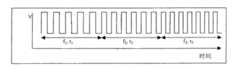
附图的图1是仅使用单一中间频率的现有技术的频率阶跃方法的示意性电压对时间曲线。Figure 1 of the accompanying drawings is a schematic voltage versus time curve for a prior art frequency step method using only a single intermediate frequency.
图2和3示出本发明的两个频率阶跃方法的两个不同的频率对时间曲线。Figures 2 and 3 show two different frequency versus time curves for the two frequency step methods of the present invention.
图4示出现有技术显示器的等效电路和低频率驱动中的电压对位置曲线。Figure 4 shows the equivalent circuit of a prior art display and the voltage versus position curve in low frequency drive.
图5示出了与图4的那些类似的等效电路和电压对位置曲线,但示出了与图4中相同的现有技术显示器的高频率驱动期间的情况。Figure 5 shows equivalent circuits and voltage versus position curves similar to those of Figure 4, but during high frequency drive of the same prior art display as in Figure 4.
图6示出了与图5的那些类似的等效电路和电压对位置曲线,但示出了本发明的多点接触显示器的高频率驱动期间的情况。Figure 6 shows equivalent circuits and voltage versus position curves similar to those of Figure 5, but during high frequency driving of the multi-touch display of the present invention.
如在上面所指出的,本发明提供用于驱动介电泳显示器的频率阶跃方法(以及使用该方法的相应显示器)和多点接触显示器。本发明的这两方面将在下面分别地进行主要描述,但是应该理解,单个物理显示器可以使用本发明的两方面。实际上,由于下面所解释的原因,对于使用频率阶跃方法驱动的显示器也使用多点接触构造是有利的。As noted above, the present invention provides a frequency stepping method for driving dielectrophoretic displays (and corresponding displays using this method) and multi-touch displays. These two aspects of the invention will be primarily described separately below, but it should be understood that a single physical display may use both aspects of the invention. In fact, for reasons explained below, it is advantageous to use a multi-touch configuration also for displays driven using the frequency step method.
本发明的频率阶跃方法是用于操作介电泳显示器的方法,该介电泳显示器是前述的美国专利No.7,116,466的变频驱动方法的变形。本发明的方法中,不仅使用引起粒子经历电泳运动并产生第一光学状态的低频率,以及引起粒子经历介电泳运动并产生与第一光学状态不同的第二光学状态的高频率来驱动显示器,而且还使用至少多个中间频率来驱动该显示器。因此,在一系列阶跃中而不是如现有技术的方法中的仅在两个阶跃中实现使从电泳到介电泳的粒子移动的改变所需要的频率的增加。The frequency step method of the present invention is a method for operating a dielectrophoretic display that is a variation of the variable frequency drive method of the aforementioned US Patent No. 7,116,466. In the method of the present invention, the display is driven using not only a low frequency that causes the particles to undergo electrophoretic motion and produce a first optical state, but also a high frequency that causes the particles to undergo dielectrophoretic motion and produce a second optical state different from the first optical state, Also, at least a plurality of intermediate frequencies are used to drive the display. Thus, the increase in frequency required to effect the change in particle movement from electrophoresis to dielectrophoresis is achieved in a series of steps rather than in only two steps as in prior art methods.
虽然频率阶跃方法能够仅使用一些频率阶跃来实现,但是期望使用大量的频率阶跃,这是因为(本发明人已经发现)单个频率阶跃越小,观察者越不可能观察到闪烁。理论上,期望通过连续地改变电场的频率来实现从显示器的低频关闭状态到高频开启状态的转变,没有离散的频率阶跃。然而,这样的连续频率改变一般不能利用通常用于驱动电光显示器的类型的驱动电路来实现。因此,实践中通常使用连续施加的离散频率来实现频率阶跃方法,但仍然期望保持单个频率阶跃小,使得介电泳媒质实际上经历驱动频率的逐渐增加。While the frequency step method can be implemented using only a few frequency steps, it is desirable to use a large number of frequency steps because (the inventors have found) that the smaller the individual frequency steps, the less likely the observer is to observe flicker. Theoretically, it is expected that the transition from the low frequency off state of the display to the high frequency on state is achieved by continuously varying the frequency of the electric field, without discrete frequency steps. However, such continuous frequency changes generally cannot be achieved with drive circuits of the type commonly used to drive electro-optic displays. Therefore, in practice it is common to implement the frequency step approach using continuously applied discrete frequencies, but it is still desirable to keep the individual frequency steps small so that the dielectrophoretic medium actually experiences a gradual increase in the driving frequency.
如在上面所讨论的,尽管施加每个频率的最佳周期随着驱动电路的特性和所使用的特定介电泳媒质而改变,但是施加每个频率的周期也是重要的。期望给观察者在光学透射中的光滑连续改变的印象而不是一系列离散阶跃。当频率改变时振幅(即,施加在显示器上的电压)可以或不必保持恒定,但是使用恒定的振幅一般是优选的,这是因为这便于使用更简单的驱动电路。另一方面,由于低频率阶跃通常在较低电压处执行良好,因此在低频率阶跃中使用较低电压将减少显示器的总功耗。As discussed above, the period at which each frequency is applied is also important, although the optimum period for applying each frequency varies with the characteristics of the driving circuit and the particular dielectrophoretic medium used. It is desirable to give the observer the impression of a smooth continuous change in optical transmission rather than a series of discrete steps. The amplitude (ie, the voltage applied to the display) may or may not remain constant as the frequency changes, but using a constant amplitude is generally preferred because it facilitates the use of simpler drive circuits. On the other hand, since low frequency steps generally perform well at lower voltages, using lower voltages for low frequency steps will reduce the overall power consumption of the display.
附图的图1示意性示出了对于一个现有技术的频率阶跃方法的电压与时间曲线。如在图1中所示,使用方波交流电压驱动显示器,在频率f1持续时间t1,然后在较高的频率f2持续时间t2,此后在更高的频率f3持续时间t3。Figure 1 of the accompanying drawings schematically shows voltage versus time curves for a prior art frequency stepping method. As shown in Figure 1, the display is driven with a square wave AC voltage at frequencyf1 for timet1 , then at a higher frequencyf2 for timet2 , thereafter at a higher frequencyf3 for timet3 .
相反地,下表示出了用于驱动介电泳显示器从其关闭到其开启状态的本发明的更典型的波形。Conversely, the table below shows more typical waveforms of the present invention for driving a dielectrophoretic display from its off state to its on state.
表
从该表可以看出该优选的波形阶跃从100Hz到500Hz,在16个分离的每个25Hz的阶跃中,每个阶跃之间的周期为0.2秒。已经发现这样的驱动频率的逐渐增加导致显示器在开启状态中提高的(增加的)透射。基于显微观察,可以相信(虽然本发明绝不被该理念所限制)该提高的透射是由于囊的壁或小滴处改进的色素包装。采用大量的以这种方式的较小频率阶跃还提供了从显示器的关闭到开启状态的快速且光滑转变;观察者看不到单个小阶跃,反之当仅使用单独大阶跃或者少量的大阶跃时,观察者可以看见在转变期间的不期望的闪烁。From the table it can be seen that the preferred waveform steps from 100 Hz to 500 Hz in 16 separate steps of 25 Hz each with a period of 0.2 seconds between each step. It has been found that such a gradual increase in drive frequency results in improved (increased) transmission of the display in the on state. Based on microscopic observations, it is believed (although the invention is in no way limited by this idea) that the enhanced transmission is due to improved pigment packing at the wall of the capsule or at the droplet. Using a large number of smaller frequency steps in this way also provides a quick and smooth transition from the off to on state of the display; a single small step is not visible to the observer, whereas when only a single large step or a small number of With large steps, the observer may see undesired flickering during transitions.
图2和图3示出对于本发明的均在恒定电压下操作的两个不同频率阶跃方法的频率对时间的曲线。在图2和图3中,假定介电泳媒质具有30Hz的最佳关闭频率和1000Hz的最佳开启频率,这些是在实践中得到的典型频率。因此,在每种情况下转变范围是60-500Hz。在图2的方法中,施加277个不同频率,每个频率持续0.05秒,频率随时间成指数地增加。可以看到显示器在转变范围中花费了开启转变的总计14秒中的大约8秒,并且已经发现在转变范围中的该驻留时间足以提供良好的开启状态。Figures 2 and 3 show frequency versus time curves for two different frequency step methods of the present invention, both operating at constant voltage. In Figures 2 and 3, it is assumed that the dielectrophoretic medium has an optimum off frequency of 30 Hz and an optimum on frequency of 1000 Hz, which are typical frequencies obtained in practice. Thus, the transition range is 60-500 Hz in each case. In the method of Figure 2, 277 different frequencies are applied, each lasting 0.05 seconds, with the frequency increasing exponentially with time. It can be seen that the display spends approximately 8 seconds in the transition range out of a total of 14 seconds for the on transition, and this dwell time in the transition range has been found to be sufficient to provide a good on state.
图3示出了频率对时间的曲线,利用简单电路该曲线比图2的指数频率曲线更容易实现。在图3中,频率快速地从最佳关闭频率30Hz增加到在三个阶跃中的转变范围的较低端的60Hz,每个频率被施加了0.2秒。在转变区域,频率以许多非常小的频率阶跃(合适的,1Hz)线性地增加,施加每个频率为0.03秒的最小周期。一旦频率达到转变区域的上限500Hz,则该频率以50Hz的阶跃上升,施加每个频率为0.2秒。该频率对时间曲线允许显示器在转变范围中花费了16秒的总转变时间中的多于13秒,并且产生非常接近于最佳的开启状态。Figure 3 shows a frequency versus time curve which is easier to implement than the exponential frequency curve of Figure 2 with a simple circuit. In Figure 3, the frequency is rapidly increased from the optimum off frequency of 30 Hz to 60 Hz at the lower end of the transition range in three steps, each applied for 0.2 seconds. In the transition region, the frequency is increased linearly in many very small frequency steps (suitable, 1 Hz), imposing a minimum period of 0.03 seconds per frequency. Once the frequency reached the upper limit of the transition region, 500 Hz, the frequency was increased in 50 Hz steps, applying each frequency for 0.2 seconds. This frequency versus time curve allows the display to spend more than 13 seconds of the total transition time of 16 seconds in the transition range and produce an on state that is very close to optimal.
本发明的频率阶跃方法和使用该方法的显示器能够包括前述美国专利No.7,116,466和2006/0038772中所描述的驱动方法的任意可选特征。因此,例如频率阶跃方法可以包括零电压的周期和驱动电压的振幅的改变。显示器可以配有布置在电极和介电泳媒质之间的绝缘层。这样的绝缘层可以具有大约109到大约1011欧姆厘米的体电阻率。在一些情况下,远离观察表面的绝缘层可以由粘附层形成。围绕粒子的流体可以已溶解或已分散在聚合物中,该聚合物在悬浮流体中的本征粘度为η并且基本不受在悬浮流体中的离子或离子化团的影响,存在于悬浮流体中的该聚合物的浓度从大约0.5η-1至大约2.0η-1。聚合物可以是聚异丁烯。该显示器可以包括与显示器邻近的彩色阵列以便其对观察者为可视的,使得被观察者感知到的显示器的颜色能够通过改变显示器的各个像素的开启和关闭光学状态而改变。The frequency stepping method of the present invention and displays using it can include any optional features of the driving methods described in the aforementioned US Patent Nos. 7,116,466 and 2006/0038772. Thus, for example, a frequency step method may include periods of zero voltage and changes in the amplitude of the drive voltage. The display can be provided with an insulating layer arranged between the electrodes and the dielectrophoretic medium. Such an insulating layer may have a volume resistivity of about 109 to about 1011 ohm-cm. In some cases, the insulating layer remote from the viewing surface may be formed by an adhesive layer. The fluid surrounding the particle may have been dissolved or dispersed in a polymer that has an intrinsic viscosity η in the suspending fluid and is substantially unaffected by ions or ionized groups in the suspending fluid, present in the suspending fluid The concentration of the polymer is from about 0.5η−1 to about 2.0η−1 . The polymer may be polyisobutylene. The display may include a color array adjacent to the display so that it is visible to a viewer such that the color of the display perceived by the viewer can be changed by changing the on and off optical states of individual pixels of the display.
本发明的频率阶跃方法能够产生至完全开启的、高透射状态的光滑且快速的转变,并且还可以被用于驱动显示器至中灰度级,即至介于完全开启和完全关闭状态之间的光学状态。The frequency stepping method of the present invention is capable of producing a smooth and fast transition to the fully on, highly transmissive state, and can also be used to drive displays to mid-gray levels, i.e. to between the fully on and fully off states optical state.
本发明的第二方面涉及一种方法,该方法中光透射电极(通过其观察电泳或介电泳显示器)被连接至电压源。如在前述的数个E Ink和MIT的专利和申请中所讨论的,电泳媒质典型地具有大约1010欧姆厘米的高体电阻率,使得当横跨媒质施加DC电场时,提取的电流非常低并且仅由通过媒质的电泄漏产生。然而,当施加AC电场时电泳媒质用作为电容器,其在每个交流电流的半周期中被充电和放电。换句话说,电泳媒质的阻抗与驱动频率成反比例,并且在高频工作期间流动的电流比直流驱动期间流动的电流大得多。A second aspect of the invention relates to a method in which a light transmissive electrode through which an electrophoretic or dielectrophoretic display is viewed is connected to a voltage source. As discussed in several of the aforementioned E Ink and MIT patents and applications, electrophoretic media typically have high bulk resistivities on the order of 1010 ohm-cm such that when a DC electric field is applied across the media, the current drawn is very low And only by electrical leakage through the medium. However, the electrophoretic medium acts as a capacitor when an AC electric field is applied, which is charged and discharged in each half cycle of the alternating current. In other words, the impedance of the electrophoretic medium is inversely proportional to the driving frequency, and a much larger current flows during high-frequency operation than during DC driving.
通常用于形成电泳和介电泳显示器中的光透射电极(其典型地是延伸跨过整个显示器的单个电极)的材料具有适中的电导率;例如铟锡氧化物(ITO)具有大约300欧姆/平方的电导率。因此,当大显示器(例如,11*14英寸或279*355mm)在高频率处被驱动时,在光透射电极中的用以连接该光透射电极至电压源的导体接触该光透射电极的所在点、与在远离该导体的光透射电极上的点之间能够发生相当大的电压降。(该导体不需要是光透射并且典型地是金属迹线,其通常具有比光透射电极的电导率大得多的电导率)Materials commonly used to form the light-transmissive electrodes (which are typically a single electrode extending across the entire display) in electrophoretic and dielectrophoretic displays have moderate electrical conductivity; for example indium tin oxide (ITO) has about 300 ohms/square conductivity. Therefore, when a large display (for example, 11*14 inches or 279*355mm) is driven at a high frequency, the conductor in the light-transmitting electrode used to connect the light-transmitting electrode to a voltage source contacts where the light-transmitting electrode A considerable voltage drop can occur between the point, and the point on the light-transmitting electrode remote from the conductor. (The conductor need not be light transmissive and is typically a metal trace, which usually has a conductivity much greater than that of the light transmissive electrode)
附图的图4和5示出了这样的显示器在DC和高频AC驱动期间的不同情况。图4示出在DC(或非常低的频率的AC)驱动期间的情况。电泳媒质实际上用作为一系列的电容器(严格地讲,为与非常高阻抗的电阻器并联的一系列电容器,但这对于本发明的目的而言没有实质性差异),并且在光透射层中基本上没有电压降。相反地,图5示出在高频AC驱动期间的情况。电泳媒质用作为一系列与光透射电极的内电阻串联的电阻器,并且在光透射电极中发生相当大的电压降,使得在该电极上的电压根据与导体的距离而变化。Figures 4 and 5 of the accompanying drawings show such a display differently during DC and high frequency AC driving. Figure 4 shows the situation during DC (or very low frequency AC) driving. The electrophoretic medium actually acts as a series of capacitors (strictly speaking, a series of capacitors in parallel with very high impedance resistors, but this makes no substantial difference for the purposes of this invention), and in the light transmissive layer Basically no voltage drop. In contrast, Fig. 5 shows the situation during high frequency AC driving. The electrophoretic medium acts as a series of resistors in series with the internal resistance of the light-transmissive electrode, and a considerable voltage drop occurs in the light-transmissive electrode, so that the voltage across the electrode varies according to the distance from the conductor.
在光透射电极中电极电压的变化是不期望的,这是因为它们在意图受相同电场的同一显示器的不同部分中产生不同的电场,并且因此导致显示器的不同部分以不同速率转换。例如,如果将显示器从(比如说)白色背景上的黑色文本重写至纯黑色,在光透射电极中电极电压的变化将引起可见的“波”,其中与导体最接近的白色背景部分将首先转换,而与该导体相距较远的部分将随后转换。这样的波伪像通常是令显示器的用户讨厌的。Variations in electrode voltage in light transmissive electrodes are undesirable because they generate different electric fields in different parts of the same display that are intended to be subjected to the same electric field, and thus cause different parts of the display to switch at different rates. For example, if a display is rewritten from black text on (say) a white background to pure black, the change in electrode voltage in the light-transmitting electrode will cause a visible "wave" in which the portion of the white background closest to the conductor will first converted, and the part further away from the conductor will be converted subsequently. Such wave artifacts are often annoying to users of displays.
一种减少这样的可见的伪像的方法是提供更导电的光透射电极。然而,在当前技术状况下,这样的较高导电性的实现是以牺牲电极的光学透射为代价的。另外,用于形成光透射电极的许多材料,例如ITO是着色的,并且通过增加其厚度来增加的光透射电极的导电性可能会导致显示器的不期望的着色。One way to reduce such visible artifacts is to provide more conductive light-transmissive electrodes. However, in the current state of the art, such higher conductivity is achieved at the expense of the optical transmission of the electrodes. In addition, many materials used to form light-transmitting electrodes, such as ITO, are colored, and increasing the conductivity of the light-transmitting electrode by increasing its thickness may lead to undesired coloring of the display.
根据本发明,导体在多个间隔开的点处被连接到光透射电极。例如,在矩形显示器中,导体能够被布置为在电极的每个边缘的中点处与光透射电极接触。本发明在足够大的显示器中尤其有用,所说的足够大是指显示器上的至少一个点与单个导体连接点的距离为200mm或更大。实际中,在建筑中使用的大多数可变透射窗口将至少这么大。在本发明的优选的形式中,导体具有以围绕光透射电极的整个外周或大体整个外周延伸的导电迹线的形式。这将导体尽可能地靠近显示器的有源区域中的所有点放置,因此最小化在高频驱动期间的转换非一致性,而不牺牲光透射或产生不期望的颜色。这样的导电迹线应该具有尽可能高的电导率;例如,已经发现丝网印刷具有电导率为大约0.02欧姆/平方的银漆在多达11*14英寸(279*355mm)的显示器上产生一致性的转换,然而丝网印刷具有电导率为大约15欧姆/平方的碳漆在这样大的显示器上不能令人满意。According to the invention, the conductor is connected to the light transmissive electrode at a plurality of spaced apart points. For example, in a rectangular display, a conductor can be arranged to contact the light transmissive electrode at the midpoint of each edge of the electrode. The invention is particularly useful in displays that are large enough that at least one point on the display is 200mm or more from a single conductor connection point. In practice, most variable transmission windows used in architecture will be at least this large. In a preferred form of the invention, the conductor is in the form of a conductive trace extending around the entire or substantially the entire circumference of the light transmissive electrode. This places the conductors as close as possible to all points in the active area of the display, thus minimizing switching non-uniformity during high-frequency drive without sacrificing light transmission or producing undesired colors. Such conductive traces should have as high a conductivity as possible; for example, it has been found that screen printing silver paint with a conductivity of about 0.02 ohms/square produces consistent However, screen printed carbon paint with a conductivity of about 15 ohms/square is not satisfactory on such a large display.
在附图的图6中示出了提供围绕显示器的外周的导电迹线的效果。因为光透射电极的整个外周与导电迹线接触,整个外周保持在迹线的电压V处。对比图5和图6,可以看到在图6中所示的本发明的显示器中的在光透射电极的间隔开的点处存在的电压之间的最大差异与在图5中所示的现有技术显示器中的相比小很多。The effect of providing conductive traces around the periphery of the display is shown in Figure 6 of the accompanying drawings. Because the entire periphery of the light-transmissive electrode is in contact with the conductive trace, the entire periphery remains at the voltage V of the trace. Comparing Figures 5 and 6, it can be seen that the maximum difference between the voltages present at spaced points of the light-transmitting electrodes in the display of the invention shown in Figure Much smaller than those in state-of-the-art displays.
本发明不仅提供在大显示器中的更一致性的转换,还由于在光透射电极中的减少的电阻热而提高了显示器的可靠性和耐用性。应该理解,可变透射窗口具有在电泳媒质的相对侧上的两个光透射电极,并且在这样的窗口中通常期望应用本发明到这两个光透射电极,但是我们并不完全排除将本发明仅应用到这两个光透射电极中的一个的可能性。然而,本发明的使用不限于可变透射窗口;本发明能够被应用到具有一个光透射电极和一个或多个不透明电极的显示器,例如用在电子书阅读器和类似设备中的显示器,以在当其需要或者期望使用需要高频率驱动的驱动方案时改善在这样的显示器中的转换的一致性。The present invention not only provides more consistent switching in large displays, but also improves the reliability and durability of the display due to reduced resistive heating in the light transmissive electrodes. It should be understood that variable transmission windows have two light-transmitting electrodes on opposite sides of the electrophoretic medium, and that it is generally desirable to apply the invention to both light-transmitting electrodes in such windows, but we do not entirely rule out the application of the invention to the two light-transmitting electrodes. Possibility to apply to only one of the two light-transmitting electrodes. However, the use of the invention is not limited to variable transmission windows; the invention can be applied to displays having one light-transmissive electrode and one or more opaque electrodes, such as those used in e-book readers and similar devices, to Improving the consistency of transitions in such displays when it is required or desired to use drive schemes that require high frequency drive.
Claims (8)
Applications Claiming Priority (5)
| Application Number | Priority Date | Filing Date | Title |
|---|---|---|---|
| US88787607P | 2007-02-02 | 2007-02-02 | |
| US60/887,876 | 2007-02-02 | ||
| US11/949,316US20080136774A1 (en) | 2004-07-27 | 2007-12-03 | Methods for driving electrophoretic displays using dielectrophoretic forces |
| US11/949,316 | 2007-12-03 | ||
| PCT/US2008/051885WO2008097721A1 (en) | 2007-02-02 | 2008-01-24 | Methods for driving electrophoretic displays using dielectrophoretic forces |
Related Child Applications (1)
| Application Number | Title | Priority Date | Filing Date |
|---|---|---|---|
| CN201310418237.7ADivisionCN103474034B (en) | 2007-02-02 | 2008-01-24 | Use the method that dielectrophoretic force drives electrophoretic display |
Publications (2)
| Publication Number | Publication Date |
|---|---|
| CN101601080A CN101601080A (en) | 2009-12-09 |
| CN101601080Btrue CN101601080B (en) | 2013-10-23 |
Family
ID=39497400
Family Applications (1)
| Application Number | Title | Priority Date | Filing Date |
|---|---|---|---|
| CN2008800039521AActiveCN101601080B (en) | 2007-02-02 | 2008-01-24 | Method for driving electrophoretic displays using dielectrophoretic forces |
Country Status (5)
| Country | Link |
|---|---|
| US (1) | US20080136774A1 (en) |
| EP (2) | EP2126885B1 (en) |
| JP (3) | JP5632164B2 (en) |
| CN (1) | CN101601080B (en) |
| WO (1) | WO2008097721A1 (en) |
Families Citing this family (151)
| Publication number | Priority date | Publication date | Assignee | Title |
|---|---|---|---|---|
| US7848006B2 (en) | 1995-07-20 | 2010-12-07 | E Ink Corporation | Electrophoretic displays with controlled amounts of pigment |
| US7583251B2 (en) | 1995-07-20 | 2009-09-01 | E Ink Corporation | Dielectrophoretic displays |
| US7999787B2 (en) | 1995-07-20 | 2011-08-16 | E Ink Corporation | Methods for driving electrophoretic displays using dielectrophoretic forces |
| US8040594B2 (en) | 1997-08-28 | 2011-10-18 | E Ink Corporation | Multi-color electrophoretic displays |
| DE69920228T2 (en) | 1998-07-08 | 2005-01-27 | E-Ink Corp., Cambridge | METHOD FOR IMPROVING COLOR REPRODUCTION IN ELECTROPHORETIC DEVICES USING MICROCAPSULES |
| AU2002250304A1 (en) | 2001-03-13 | 2002-09-24 | E Ink Corporation | Apparatus for displaying drawings |
| US8390918B2 (en) | 2001-04-02 | 2013-03-05 | E Ink Corporation | Electrophoretic displays with controlled amounts of pigment |
| US7679814B2 (en) | 2001-04-02 | 2010-03-16 | E Ink Corporation | Materials for use in electrophoretic displays |
| US9530363B2 (en) | 2001-11-20 | 2016-12-27 | E Ink Corporation | Methods and apparatus for driving electro-optic displays |
| US7223672B2 (en) | 2002-04-24 | 2007-05-29 | E Ink Corporation | Processes for forming backplanes for electro-optic displays |
| US7843621B2 (en) | 2002-06-10 | 2010-11-30 | E Ink Corporation | Components and testing methods for use in the production of electro-optic displays |
| US8363299B2 (en) | 2002-06-10 | 2013-01-29 | E Ink Corporation | Electro-optic displays, and processes for the production thereof |
| US7839564B2 (en) | 2002-09-03 | 2010-11-23 | E Ink Corporation | Components and methods for use in electro-optic displays |
| US20130063333A1 (en) | 2002-10-16 | 2013-03-14 | E Ink Corporation | Electrophoretic displays |
| US10726798B2 (en) | 2003-03-31 | 2020-07-28 | E Ink Corporation | Methods for operating electro-optic displays |
| US20110164301A1 (en) | 2003-11-05 | 2011-07-07 | E Ink Corporation | Electro-optic displays, and materials for use therein |
| US8177942B2 (en) | 2003-11-05 | 2012-05-15 | E Ink Corporation | Electro-optic displays, and materials for use therein |
| US11250794B2 (en) | 2004-07-27 | 2022-02-15 | E Ink Corporation | Methods for driving electrophoretic displays using dielectrophoretic forces |
| US7843624B2 (en) | 2006-03-08 | 2010-11-30 | E Ink Corporation | Electro-optic displays, and materials and methods for production thereof |
| US8390301B2 (en) | 2006-03-08 | 2013-03-05 | E Ink Corporation | Electro-optic displays, and materials and methods for production thereof |
| US7649666B2 (en) | 2006-12-07 | 2010-01-19 | E Ink Corporation | Components and methods for use in electro-optic displays |
| KR101256709B1 (en) | 2007-01-22 | 2013-04-19 | 이 잉크 코포레이션 | Multi-layer sheet for use in electro-optic displays |
| US7688497B2 (en)* | 2007-01-22 | 2010-03-30 | E Ink Corporation | Multi-layer sheet for use in electro-optic displays |
| US7826129B2 (en) | 2007-03-06 | 2010-11-02 | E Ink Corporation | Materials for use in electrophoretic displays |
| US9199441B2 (en) | 2007-06-28 | 2015-12-01 | E Ink Corporation | Processes for the production of electro-optic displays, and color filters for use therein |
| US8034209B2 (en) | 2007-06-29 | 2011-10-11 | E Ink Corporation | Electro-optic displays, and materials and methods for production thereof |
| US20090122389A1 (en) | 2007-11-14 | 2009-05-14 | E Ink Corporation | Electro-optic assemblies, and adhesives and binders for use therein |
| KR101237263B1 (en) | 2008-03-21 | 2013-02-27 | 이 잉크 코포레이션 | Electro-optic displays and color filters |
| KR101214877B1 (en) | 2008-04-11 | 2012-12-24 | 이 잉크 코포레이션 | Methods for driving electro-optic displays |
| JP2011520137A (en) | 2008-04-14 | 2011-07-14 | イー インク コーポレイション | Method for driving an electro-optic display |
| TWI484273B (en) | 2009-02-09 | 2015-05-11 | E Ink Corp | Electrophoretic particles |
| US8098418B2 (en) | 2009-03-03 | 2012-01-17 | E. Ink Corporation | Electro-optic displays, and color filters for use therein |
| US9390661B2 (en) | 2009-09-15 | 2016-07-12 | E Ink California, Llc | Display controller system |
| US8654436B1 (en) | 2009-10-30 | 2014-02-18 | E Ink Corporation | Particles for use in electrophoretic displays |
| WO2011097228A2 (en) | 2010-02-02 | 2011-08-11 | E Ink Corporation | Method for driving electro-optic displays |
| US8446664B2 (en) | 2010-04-02 | 2013-05-21 | E Ink Corporation | Electrophoretic media, and materials for use therein |
| TWI591604B (en) | 2010-04-09 | 2017-07-11 | 電子墨水股份有限公司 | Methods for driving electro-optic displays |
| TWI484275B (en) | 2010-05-21 | 2015-05-11 | E Ink Corp | Electro-optic display, method for driving the same and microcavity electrophoretic display |
| JP5660853B2 (en)* | 2010-11-05 | 2015-01-28 | 三菱鉛筆株式会社 | Electrophoretic display medium sheet and electrophoretic display medium using the same |
| CN106448574B (en) | 2012-02-01 | 2019-07-12 | 伊英克公司 | Method for driving electro-optic displays |
| US11030936B2 (en) | 2012-02-01 | 2021-06-08 | E Ink Corporation | Methods and apparatus for operating an electro-optic display in white mode |
| JP2015143725A (en)* | 2012-05-17 | 2015-08-06 | シャープ株式会社 | Display device |
| US9513743B2 (en) | 2012-06-01 | 2016-12-06 | E Ink Corporation | Methods for driving electro-optic displays |
| US10282033B2 (en) | 2012-06-01 | 2019-05-07 | E Ink Corporation | Methods for updating electro-optic displays when drawing or writing on the display |
| US10037735B2 (en) | 2012-11-16 | 2018-07-31 | E Ink Corporation | Active matrix display with dual driving modes |
| US9721495B2 (en) | 2013-02-27 | 2017-08-01 | E Ink Corporation | Methods for driving electro-optic displays |
| CN105190740B (en) | 2013-03-01 | 2020-07-10 | 伊英克公司 | Method for driving an electro-optical display |
| US9697778B2 (en) | 2013-05-14 | 2017-07-04 | E Ink Corporation | Reverse driving pulses in electrophoretic displays |
| US9620048B2 (en) | 2013-07-30 | 2017-04-11 | E Ink Corporation | Methods for driving electro-optic displays |
| KR102197976B1 (en) | 2013-07-31 | 2021-01-04 | 이 잉크 코포레이션 | Methods for driving electro-optic displays |
| TWI550332B (en) | 2013-10-07 | 2016-09-21 | 電子墨水加利福尼亞有限責任公司 | Driving methods for color display device |
| US10726760B2 (en) | 2013-10-07 | 2020-07-28 | E Ink California, Llc | Driving methods to produce a mixed color state for an electrophoretic display |
| US10380931B2 (en) | 2013-10-07 | 2019-08-13 | E Ink California, Llc | Driving methods for color display device |
| US10657869B2 (en) | 2014-09-10 | 2020-05-19 | E Ink Corporation | Methods for driving color electrophoretic displays |
| EP3191892B1 (en) | 2014-09-10 | 2020-01-01 | E Ink Corporation | Colored electrophoretic displays |
| WO2016073914A1 (en) | 2014-11-07 | 2016-05-12 | E Ink Corporation | Applications of electro-optic displays |
| JP6430021B2 (en) | 2015-01-05 | 2018-11-28 | イー インク コーポレイション | Electro-optic display and method for driving the same |
| US10197883B2 (en) | 2015-01-05 | 2019-02-05 | E Ink Corporation | Electro-optic displays, and methods for driving same |
| EP3251112A4 (en) | 2015-01-30 | 2018-10-24 | E Ink Corporation | Font control for electro-optic displays and related apparatus and methods |
| ES2951682T3 (en) | 2015-02-04 | 2023-10-24 | E Ink Corp | Electro-optical display elements displaying in dark mode and light mode, and related apparatus and methods |
| CN107646132B (en) | 2015-04-27 | 2021-02-12 | 伊英克公司 | Method and apparatus for driving display system |
| US10997930B2 (en) | 2015-05-27 | 2021-05-04 | E Ink Corporation | Methods and circuitry for driving display devices |
| US10040954B2 (en) | 2015-05-28 | 2018-08-07 | E Ink California, Llc | Electrophoretic medium comprising a mixture of charge control agents |
| US11087644B2 (en) | 2015-08-19 | 2021-08-10 | E Ink Corporation | Displays intended for use in architectural applications |
| CN107924100B (en) | 2015-08-31 | 2021-03-23 | 伊英克公司 | Electronically Erase Drawing Device |
| EP3350798B1 (en) | 2015-09-16 | 2023-07-26 | E Ink Corporation | Apparatus and methods for driving displays |
| US10803813B2 (en) | 2015-09-16 | 2020-10-13 | E Ink Corporation | Apparatus and methods for driving displays |
| US11657774B2 (en) | 2015-09-16 | 2023-05-23 | E Ink Corporation | Apparatus and methods for driving displays |
| WO2017059179A1 (en) | 2015-10-01 | 2017-04-06 | E Ink Corporation | Variable color and transmission coverings |
| CN108138038B (en) | 2015-10-06 | 2020-10-09 | 伊英克公司 | Improved low temperature electrophoretic media |
| EP3362853A4 (en) | 2015-10-12 | 2018-10-31 | E Ink California, LLC | Electrophoretic display device |
| JP6660465B2 (en) | 2015-11-11 | 2020-03-11 | イー インク コーポレイション | Functionalized quinacridone pigments |
| US10795233B2 (en) | 2015-11-18 | 2020-10-06 | E Ink Corporation | Electro-optic displays |
| ES3029534T3 (en) | 2016-02-08 | 2025-06-24 | E Ink Corp | Methods and apparatus for operating an electro-optic display in white mode |
| US10572707B2 (en)* | 2016-02-09 | 2020-02-25 | Synaptics Incorporated | Transparent fingerprint sensor pattern |
| US10593272B2 (en) | 2016-03-09 | 2020-03-17 | E Ink Corporation | Drivers providing DC-balanced refresh sequences for color electrophoretic displays |
| CN113823232B (en) | 2016-03-09 | 2024-01-19 | 伊英克公司 | Method for driving electro-optic display |
| JP6599569B2 (en) | 2016-05-24 | 2019-10-30 | イー インク コーポレイション | Method for rendering an image on a display, an apparatus comprising a display device and a computing device, and a non-transitory computer storage medium |
| US10527899B2 (en) | 2016-05-31 | 2020-01-07 | E Ink Corporation | Backplanes for electro-optic displays |
| RU2754814C2 (en) | 2017-03-03 | 2021-09-07 | Е Инк Корпорэйшн | Electrical-optical displays and their switching methods |
| CN112259034B (en) | 2017-03-06 | 2024-04-23 | 伊英克公司 | Method and apparatus for presenting color images |
| US10444592B2 (en) | 2017-03-09 | 2019-10-15 | E Ink Corporation | Methods and systems for transforming RGB image data to a reduced color set for electro-optic displays |
| KR102531228B1 (en) | 2017-04-04 | 2023-05-10 | 이 잉크 코포레이션 | Methods for driving electro-optic displays |
| KR20190133292A (en) | 2017-05-30 | 2019-12-02 | 이 잉크 코포레이션 | Electro-optic displays |
| US11404013B2 (en) | 2017-05-30 | 2022-08-02 | E Ink Corporation | Electro-optic displays with resistors for discharging remnant charges |
| US11721295B2 (en) | 2017-09-12 | 2023-08-08 | E Ink Corporation | Electro-optic displays, and methods for driving same |
| WO2019055486A1 (en) | 2017-09-12 | 2019-03-21 | E Ink Corporation | Methods for driving electro-optic displays |
| US10882042B2 (en) | 2017-10-18 | 2021-01-05 | E Ink Corporation | Digital microfluidic devices including dual substrates with thin-film transistors and capacitive sensing |
| KR102184385B1 (en)* | 2017-11-03 | 2020-11-30 | 주식회사 엘지화학 | Transmittance controllable device |
| JP2021507293A (en) | 2017-12-19 | 2021-02-22 | イー インク コーポレイション | Application of electro-optical display |
| PL3729191T3 (en) | 2017-12-22 | 2023-10-09 | E Ink Corporation | ELECTROOPTIC DISPLAYS AND METHODS OF CONTROL THEM |
| WO2019144097A1 (en) | 2018-01-22 | 2019-07-25 | E Ink Corporation | Electro-optic displays, and methods for driving same |
| CN112313572B (en)* | 2018-06-28 | 2024-08-16 | 伊英克公司 | Driving method for variable transmission electrophoretic medium |
| KR102609672B1 (en) | 2018-07-17 | 2023-12-05 | 이 잉크 코포레이션 | Electro-optical displays and driving methods |
| US11314098B2 (en) | 2018-08-10 | 2022-04-26 | E Ink California, Llc | Switchable light-collimating layer with reflector |
| US11397366B2 (en) | 2018-08-10 | 2022-07-26 | E Ink California, Llc | Switchable light-collimating layer including bistable electrophoretic fluid |
| CN112470066A (en) | 2018-08-10 | 2021-03-09 | 伊英克加利福尼亚有限责任公司 | Drive waveform for switchable light collimating layer comprising a bistable electrophoretic fluid |
| US11353759B2 (en) | 2018-09-17 | 2022-06-07 | Nuclera Nucleics Ltd. | Backplanes with hexagonal and triangular electrodes |
| TWI763526B (en) | 2018-10-15 | 2022-05-01 | 美商電子墨水股份有限公司 | Method for dispensing an aqueous chemical species to a surface |
| CA3115833C (en) | 2018-11-30 | 2023-01-24 | E Ink California, Llc | Electro-optic displays and driving methods |
| CN113168005B (en)* | 2018-12-13 | 2023-05-02 | 伊英克公司 | Illumination system for reflective display |
| ES3031587T3 (en) | 2019-05-07 | 2025-07-09 | E Ink Corp | Driving methods for a variable light transmission device |
| US11460722B2 (en) | 2019-05-10 | 2022-10-04 | E Ink Corporation | Colored electrophoretic displays |
| WO2021097179A1 (en) | 2019-11-14 | 2021-05-20 | E Ink Corporation | Methods for driving electro-optic displays |
| JP2022553872A (en) | 2019-11-18 | 2022-12-26 | イー インク コーポレイション | How to drive an electro-optic display |
| JP7629031B2 (en) | 2020-05-31 | 2025-02-12 | イー インク コーポレイション | Electro-optic display and method for driving same - Patents.com |
| JP7496002B2 (en) | 2020-06-11 | 2024-06-05 | イー インク コーポレイション | Electro-optic display and method for driving same - Patents.com |
| KR102725786B1 (en) | 2020-08-04 | 2024-11-05 | 삼성전자주식회사 | Electronic device including display and operation method thereof |
| KR102797902B1 (en) | 2020-08-31 | 2025-04-17 | 이 잉크 코포레이션 | Electro-optical displays and driving methods |
| JP7542140B2 (en) | 2020-09-15 | 2024-08-29 | イー インク コーポレイション | Four-particle electrophoretic medium providing fast and high contrast optical state switching |
| US11846863B2 (en) | 2020-09-15 | 2023-12-19 | E Ink Corporation | Coordinated top electrode—drive electrode voltages for switching optical state of electrophoretic displays using positive and negative voltages of different magnitudes |
| US12181767B2 (en) | 2020-09-15 | 2024-12-31 | E Ink Corporation | Five-particle electrophoretic medium with improved black optical state |
| WO2022060700A1 (en) | 2020-09-15 | 2022-03-24 | E Ink Corporation | Improved driving voltages for advanced color electrophoretic displays and displays with improved driving voltages |
| EP4222732A4 (en) | 2020-10-01 | 2024-09-25 | E Ink Corporation | ELECTRO-OPTICAL DISPLAY DEVICES AND METHODS OF DRIVING THEM |
| AU2021368677B2 (en) | 2020-11-02 | 2023-12-21 | E Ink Corporation | Driving sequences to remove prior state information from color electrophoretic displays |
| WO2022094384A1 (en) | 2020-11-02 | 2022-05-05 | E Ink Corporation | Enhanced push-pull (epp) waveforms for achieving primary color sets in multi-color electrophoretic displays |
| TWI860795B (en) | 2020-11-02 | 2024-11-01 | 美商電子墨水股份有限公司 | Electronic color display |
| JP7545588B2 (en) | 2020-12-08 | 2024-09-04 | イー インク コーポレイション | Method for driving an electro-optic display - Patents.com |
| KR102809890B1 (en) | 2021-02-09 | 2025-05-19 | 이 잉크 코포레이션 | Continuous waveform driving in multi-color electrophoretic displays |
| EP4388370A4 (en) | 2021-08-18 | 2025-07-02 | E Ink Corp | METHOD FOR CONTROLLING ELECTRO-OPTICAL DISPLAYS |
| WO2023043714A1 (en) | 2021-09-14 | 2023-03-23 | E Ink Corporation | Coordinated top electrode - drive electrode voltages for switching optical state of electrophoretic displays using positive and negative voltages of different magnitudes |
| US11830448B2 (en) | 2021-11-04 | 2023-11-28 | E Ink Corporation | Methods for driving electro-optic displays |
| CN118215957A (en) | 2021-11-05 | 2024-06-18 | 伊英克公司 | Dithering based on multi-primary display mask with low halation sensitivity |
| US12339559B1 (en) | 2021-12-09 | 2025-06-24 | E Ink Corporation | Electro-optic displays and methods for discharging remnant voltage using backlight |
| US12307988B2 (en) | 2021-12-22 | 2025-05-20 | E Ink Corporation | Methods for globally applying voltages to the display pixels of electro-optic displays |
| US11922893B2 (en) | 2021-12-22 | 2024-03-05 | E Ink Corporation | High voltage driving using top plane switching with zero voltage frames between driving frames |
| CN119920209B (en) | 2021-12-27 | 2025-08-26 | 伊英克公司 | Method for driving an electro-optical display |
| CN118435269A (en) | 2021-12-30 | 2024-08-02 | 伊英克公司 | Method for driving electro-optic display |
| US20230213790A1 (en) | 2022-01-04 | 2023-07-06 | E Ink Corporation | Electrophoretic media comprising electrophoretic particles and a combination of charge control agents |
| WO2023164099A1 (en) | 2022-02-28 | 2023-08-31 | E Ink Corporation | Parking space management system |
| US11984088B2 (en) | 2022-04-27 | 2024-05-14 | E Ink Corporation | Color displays configured to convert RGB image data for display on advanced color electronic paper |
| KR20250034149A (en) | 2022-08-25 | 2025-03-10 | 이 잉크 코포레이션 | Transition drive mode for impulse balancing when switching between global color mode and direct update mode for electrophoretic displays |
| TW202424949A (en) | 2022-10-25 | 2024-06-16 | 美商電子墨水股份有限公司 | Methods for driving electro-optic displays |
| US12190836B2 (en) | 2023-01-27 | 2025-01-07 | E Ink Corporation | Multi-element pixel electrode circuits for electro-optic displays and methods for driving the same |
| WO2024182264A1 (en) | 2023-02-28 | 2024-09-06 | E Ink Corporation | Drive scheme for improved color gamut in color electrophoretic displays |
| US20240321177A1 (en) | 2023-03-24 | 2024-09-26 | E Ink Corporation | Methods for driving electro-optic displays |
| US20240402562A1 (en) | 2023-06-05 | 2024-12-05 | E Ink Corporation | Color electrophoretic medium having four pigment particle system addressable by waveforms having four voltage levels |
| AU2024306138A1 (en) | 2023-06-27 | 2025-09-04 | E Ink Corporation | Multi-particle electrophoretic display having low-flash image updates |
| WO2025006440A1 (en) | 2023-06-27 | 2025-01-02 | E Ink Corporation | Time-shifted waveforms for multi-particle electrophoretic displays providing low-flash image updates |
| US12412538B2 (en) | 2023-06-27 | 2025-09-09 | E Ink Corporation | Electrophoretic device with ambient light sensor and adaptive whiteness restoring and color balancing frontlight |
| US20250053058A1 (en) | 2023-08-08 | 2025-02-13 | E Ink Corporation | Backplanes for segmented electro-optic displays and methods of manufacturing same |
| US20250118271A1 (en) | 2023-10-05 | 2025-04-10 | E Ink Corporation | Staged gate voltage control |
| US20250138382A1 (en) | 2023-10-31 | 2025-05-01 | E Ink Corporation | Reflective display and projected capacitive touch sensor with shared transparent electrode |
| US20250191547A1 (en) | 2023-12-06 | 2025-06-12 | E Ink Corporation | Method of driving a color electophoretic display to form images without dithering |
| US20250201206A1 (en) | 2023-12-15 | 2025-06-19 | E Ink Corporation | Fast response color waveforms for multiparticle electrophoretic displays |
| WO2025136446A1 (en) | 2023-12-22 | 2025-06-26 | E Ink Corporation | Five-particle electrophoretic medium with improved black optical state |
| US20250216737A1 (en) | 2024-01-02 | 2025-07-03 | E Ink Corporation | Electrophoretic media comprising a cationic charge control agent |
| US20250224645A1 (en) | 2024-01-05 | 2025-07-10 | E Ink Corporation | Electrophoretic medium comprising particles having a pigment core and a polymeric shell |
| US20250237922A1 (en) | 2024-01-19 | 2025-07-24 | E Ink Corporation | Flexible segmented electro-optic displays and methods of manufacture |
| US20250239231A1 (en) | 2024-01-20 | 2025-07-24 | E Ink Corporation | Methods for delivering low-ghosting partial updates in color electrophoretic displays |
| US20250239232A1 (en) | 2024-01-24 | 2025-07-24 | E Ink Corporation | Methods for producing full-color epaper images with low grain |
Citations (4)
| Publication number | Priority date | Publication date | Assignee | Title |
|---|---|---|---|---|
| US3385927A (en)* | 1964-08-26 | 1968-05-28 | Stromberg Carlson Corp | Display device utilizing a medium that alters the degree of refraction of light |
| CN1589462A (en)* | 2001-11-20 | 2005-03-02 | 伊英克公司 | Method for driving a bistable electro-optic display |
| CN1659618A (en)* | 2002-06-13 | 2005-08-24 | 伊英克公司 | Method for driving electro-optic display |
| US20060038772A1 (en)* | 1995-07-20 | 2006-02-23 | E Ink Corporation | Methods for driving electrophoretic displays using dielectrophoretic forces |
Family Cites Families (182)
| Publication number | Priority date | Publication date | Assignee | Title |
|---|---|---|---|---|
| JPS5788173U (en)* | 1980-11-19 | 1982-05-31 | ||
| US4418346A (en) | 1981-05-20 | 1983-11-29 | Batchelder J Samuel | Method and apparatus for providing a dielectrophoretic display of visual information |
| JPH0518737Y2 (en)* | 1985-06-19 | 1993-05-18 | ||
| JPS638636A (en)* | 1986-06-28 | 1988-01-14 | Nippon Denso Co Ltd | Liquid crystal glare-shield type reflector |
| FR2664058B1 (en) | 1990-06-27 | 1996-09-20 | Fondis Sa | DETECTOR OF IMBULATED VOLATILE MATERIAL, IN PARTICULAR FOR A HEATING APPARATUS. |
| US5745094A (en) | 1994-12-28 | 1998-04-28 | International Business Machines Corporation | Electrophoretic display |
| US7079305B2 (en) | 2001-03-19 | 2006-07-18 | E Ink Corporation | Electrophoretic medium and process for the production thereof |
| US8139050B2 (en) | 1995-07-20 | 2012-03-20 | E Ink Corporation | Addressing schemes for electronic displays |
| US7193625B2 (en) | 1999-04-30 | 2007-03-20 | E Ink Corporation | Methods for driving electro-optic displays, and apparatus for use therein |
| US7327511B2 (en) | 2004-03-23 | 2008-02-05 | E Ink Corporation | Light modulators |
| US7411719B2 (en) | 1995-07-20 | 2008-08-12 | E Ink Corporation | Electrophoretic medium and process for the production thereof |
| US6124851A (en) | 1995-07-20 | 2000-09-26 | E Ink Corporation | Electronic book with multiple page displays |
| US6866760B2 (en) | 1998-08-27 | 2005-03-15 | E Ink Corporation | Electrophoretic medium and process for the production thereof |
| US6118426A (en) | 1995-07-20 | 2000-09-12 | E Ink Corporation | Transducers and indicators having printed displays |
| US7106296B1 (en) | 1995-07-20 | 2006-09-12 | E Ink Corporation | Electronic book with multiple page displays |
| US7259744B2 (en) | 1995-07-20 | 2007-08-21 | E Ink Corporation | Dielectrophoretic displays |
| US6120839A (en) | 1995-07-20 | 2000-09-19 | E Ink Corporation | Electro-osmotic displays and materials for making the same |
| US6262706B1 (en) | 1995-07-20 | 2001-07-17 | E Ink Corporation | Retroreflective electrophoretic displays and materials for making the same |
| US6515649B1 (en) | 1995-07-20 | 2003-02-04 | E Ink Corporation | Suspended particle displays and materials for making the same |
| US7071913B2 (en) | 1995-07-20 | 2006-07-04 | E Ink Corporation | Retroreflective electrophoretic displays and materials for making the same |
| US7167155B1 (en) | 1995-07-20 | 2007-01-23 | E Ink Corporation | Color electrophoretic displays |
| US6664944B1 (en) | 1995-07-20 | 2003-12-16 | E-Ink Corporation | Rear electrode structures for electrophoretic displays |
| US6459418B1 (en) | 1995-07-20 | 2002-10-01 | E Ink Corporation | Displays combining active and non-active inks |
| US6639578B1 (en) | 1995-07-20 | 2003-10-28 | E Ink Corporation | Flexible displays |
| US20050012980A1 (en) | 2003-05-02 | 2005-01-20 | E Ink Corporation | Electrophoretic displays with controlled amounts of pigment |
| US6710540B1 (en) | 1995-07-20 | 2004-03-23 | E Ink Corporation | Electrostatically-addressable electrophoretic display |
| US6017584A (en) | 1995-07-20 | 2000-01-25 | E Ink Corporation | Multi-color electrophoretic displays and materials for making the same |
| US6727881B1 (en) | 1995-07-20 | 2004-04-27 | E Ink Corporation | Encapsulated electrophoretic displays and methods and materials for making the same |
| US7109968B2 (en) | 1995-07-20 | 2006-09-19 | E Ink Corporation | Non-spherical cavity electrophoretic displays and methods and materials for making the same |
| US6120588A (en) | 1996-07-19 | 2000-09-19 | E Ink Corporation | Electronically addressable microencapsulated ink and display thereof |
| US6641708B1 (en)* | 1996-01-31 | 2003-11-04 | Board Of Regents, The University Of Texas System | Method and apparatus for fractionation using conventional dielectrophoresis and field flow fractionation |
| US6721083B2 (en) | 1996-07-19 | 2004-04-13 | E Ink Corporation | Electrophoretic displays using nanoparticles |
| US6538801B2 (en) | 1996-07-19 | 2003-03-25 | E Ink Corporation | Electrophoretic displays using nanoparticles |
| DE69636960C5 (en) | 1996-07-19 | 2015-07-30 | E-Ink Corp. | Electronically addressable microencapsulated ink |
| US6323989B1 (en) | 1996-07-19 | 2001-11-27 | E Ink Corporation | Electrophoretic displays using nanoparticles |
| US5930026A (en) | 1996-10-25 | 1999-07-27 | Massachusetts Institute Of Technology | Nonemissive displays and piezoelectric power supplies therefor |
| US5961804A (en) | 1997-03-18 | 1999-10-05 | Massachusetts Institute Of Technology | Microencapsulated electrophoretic display |
| US6980196B1 (en) | 1997-03-18 | 2005-12-27 | Massachusetts Institute Of Technology | Printable electronic display |
| US6252564B1 (en) | 1997-08-28 | 2001-06-26 | E Ink Corporation | Tiled displays |
| US6825829B1 (en) | 1997-08-28 | 2004-11-30 | E Ink Corporation | Adhesive backed displays |
| US6839158B2 (en) | 1997-08-28 | 2005-01-04 | E Ink Corporation | Encapsulated electrophoretic displays having a monolayer of capsules and materials and methods for making the same |
| US6177921B1 (en) | 1997-08-28 | 2001-01-23 | E Ink Corporation | Printable electrode structures for displays |
| US6232950B1 (en) | 1997-08-28 | 2001-05-15 | E Ink Corporation | Rear electrode structures for displays |
| US7002728B2 (en) | 1997-08-28 | 2006-02-21 | E Ink Corporation | Electrophoretic particles, and processes for the production thereof |
| US7247379B2 (en) | 1997-08-28 | 2007-07-24 | E Ink Corporation | Electrophoretic particles, and processes for the production thereof |
| US6300932B1 (en) | 1997-08-28 | 2001-10-09 | E Ink Corporation | Electrophoretic displays with luminescent particles and materials for making the same |
| WO1999010768A1 (en)* | 1997-08-28 | 1999-03-04 | E-Ink Corporation | Novel addressing schemes for electrophoretic displays |
| US6067185A (en) | 1997-08-28 | 2000-05-23 | E Ink Corporation | Process for creating an encapsulated electrophoretic display |
| CA2273981C (en) | 1997-12-10 | 2003-07-08 | Mitsubishi Denki Kabushiki Kaisha | Mobile communication system |
| US6445489B1 (en) | 1998-03-18 | 2002-09-03 | E Ink Corporation | Electrophoretic displays and systems for addressing such displays |
| US6704133B2 (en) | 1998-03-18 | 2004-03-09 | E-Ink Corporation | Electro-optic display overlays and systems for addressing such displays |
| US6753999B2 (en) | 1998-03-18 | 2004-06-22 | E Ink Corporation | Electrophoretic displays in portable devices and systems for addressing such displays |
| US7075502B1 (en) | 1998-04-10 | 2006-07-11 | E Ink Corporation | Full color reflective display with multichromatic sub-pixels |
| US6518949B2 (en) | 1998-04-10 | 2003-02-11 | E Ink Corporation | Electronic displays using organic-based field effect transistors |
| AU3767899A (en) | 1998-04-27 | 1999-11-16 | E-Ink Corporation | Shutter mode microencapsulated electrophoretic display |
| WO1999059101A2 (en) | 1998-05-12 | 1999-11-18 | E-Ink Corporation | Microencapsulated electrophoretic electrostatically-addressed media for drawing device applications |
| CA2333358A1 (en) | 1998-06-22 | 1999-12-29 | E Ink Corporation | Means of addressing microencapsulated display media |
| DE69920228T2 (en) | 1998-07-08 | 2005-01-27 | E-Ink Corp., Cambridge | METHOD FOR IMPROVING COLOR REPRODUCTION IN ELECTROPHORETIC DEVICES USING MICROCAPSULES |
| ATE228681T1 (en) | 1998-07-08 | 2002-12-15 | E Ink Corp | METHOD AND DEVICE FOR MEASURING THE STATE OF AN ELECTROPHORETIC DISPLAY DEVICE |
| US20030102858A1 (en) | 1998-07-08 | 2003-06-05 | E Ink Corporation | Method and apparatus for determining properties of an electrophoretic display |
| ATE215255T1 (en) | 1998-07-22 | 2002-04-15 | E Ink Corp | ELECTRONIC DISPLAY |
| US7256766B2 (en) | 1998-08-27 | 2007-08-14 | E Ink Corporation | Electrophoretic display comprising optical biasing element |
| US6225971B1 (en) | 1998-09-16 | 2001-05-01 | International Business Machines Corporation | Reflective electrophoretic display with laterally adjacent color cells using an absorbing panel |
| US6184856B1 (en) | 1998-09-16 | 2001-02-06 | International Business Machines Corporation | Transmissive electrophoretic display with laterally adjacent color cells |
| US6144361A (en) | 1998-09-16 | 2000-11-07 | International Business Machines Corporation | Transmissive electrophoretic display with vertical electrodes |
| US6271823B1 (en) | 1998-09-16 | 2001-08-07 | International Business Machines Corporation | Reflective electrophoretic display with laterally adjacent color cells using a reflective panel |
| AU6293499A (en) | 1998-10-07 | 2000-04-26 | E-Ink Corporation | Capsules for electrophoretic displays and methods for making the same |
| EP1118039B1 (en) | 1998-10-07 | 2003-02-05 | E Ink Corporation | Illumination system for nonemissive electronic displays |
| AU1811300A (en) | 1998-11-02 | 2000-05-22 | E-Ink Corporation | Broadcast system for display devices made of electronic ink |
| US6312304B1 (en) | 1998-12-15 | 2001-11-06 | E Ink Corporation | Assembly of microencapsulated electronic displays |
| US6506438B2 (en) | 1998-12-15 | 2003-01-14 | E Ink Corporation | Method for printing of transistor arrays on plastic substrates |
| WO2000036560A1 (en) | 1998-12-18 | 2000-06-22 | E Ink Corporation | Electronic ink display media for security and authentication |
| US6724519B1 (en) | 1998-12-21 | 2004-04-20 | E-Ink Corporation | Protective electrodes for electrophoretic displays |
| AU2591400A (en) | 1998-12-22 | 2000-07-12 | E-Ink Corporation | Method of manufacturing of a discrete electronic device |
| US6327072B1 (en) | 1999-04-06 | 2001-12-04 | E Ink Corporation | Microcell electrophoretic displays |
| EP1169121B1 (en) | 1999-04-06 | 2012-10-31 | E Ink Corporation | Methods for producing droplets for use in capsule-based electrophoretic displays |
| US6842657B1 (en) | 1999-04-09 | 2005-01-11 | E Ink Corporation | Reactive formation of dielectric layers and protection of organic layers in organic semiconductor device fabrication |
| US6498114B1 (en) | 1999-04-09 | 2002-12-24 | E Ink Corporation | Method for forming a patterned semiconductor film |
| US6531997B1 (en) | 1999-04-30 | 2003-03-11 | E Ink Corporation | Methods for addressing electrophoretic displays |
| US7012600B2 (en) | 1999-04-30 | 2006-03-14 | E Ink Corporation | Methods for driving bistable electro-optic displays, and apparatus for use therein |
| US6504524B1 (en) | 2000-03-08 | 2003-01-07 | E Ink Corporation | Addressing methods for displays having zero time-average field |
| US7119772B2 (en) | 1999-04-30 | 2006-10-10 | E Ink Corporation | Methods for driving bistable electro-optic displays, and apparatus for use therein |
| US7119759B2 (en) | 1999-05-03 | 2006-10-10 | E Ink Corporation | Machine-readable displays |
| WO2000067110A1 (en) | 1999-05-03 | 2000-11-09 | E Ink Corporation | Display unit for electronic shelf price label system |
| US7038655B2 (en) | 1999-05-03 | 2006-05-02 | E Ink Corporation | Electrophoretic ink composed of particles with field dependent mobilities |
| US8009348B2 (en) | 1999-05-03 | 2011-08-30 | E Ink Corporation | Machine-readable displays |
| US8115729B2 (en) | 1999-05-03 | 2012-02-14 | E Ink Corporation | Electrophoretic display element with filler particles |
| US7030412B1 (en) | 1999-05-05 | 2006-04-18 | E Ink Corporation | Minimally-patterned semiconductor devices for display applications |
| AU5779200A (en) | 1999-07-01 | 2001-01-22 | E-Ink Corporation | Electrophoretic medium provided with spacers |
| EP1196814A1 (en) | 1999-07-21 | 2002-04-17 | E Ink Corporation | Use of a storage capacitor to enhance the performance of an active matrix driven electronic display |
| AU7137800A (en) | 1999-07-21 | 2001-02-13 | E-Ink Corporation | Preferred methods for producing electrical circuit elements used to control an electronic display |
| AU7091400A (en) | 1999-08-31 | 2001-03-26 | E-Ink Corporation | Transistor for an electronically driven display |
| WO2001017040A1 (en) | 1999-08-31 | 2001-03-08 | E Ink Corporation | A solvent annealing process for forming a thin semiconductor film with advantageous properties |
| JP4114288B2 (en) | 1999-10-18 | 2008-07-09 | コニカミノルタビジネステクノロジーズ株式会社 | Image data output device and image data output method |
| US6672921B1 (en) | 2000-03-03 | 2004-01-06 | Sipix Imaging, Inc. | Manufacturing process for electrophoretic display |
| US6788449B2 (en) | 2000-03-03 | 2004-09-07 | Sipix Imaging, Inc. | Electrophoretic display and novel process for its manufacture |
| US7893435B2 (en) | 2000-04-18 | 2011-02-22 | E Ink Corporation | Flexible electronic circuits and displays including a backplane comprising a patterned metal foil having a plurality of apertures extending therethrough |
| CN1237623C (en) | 2000-04-18 | 2006-01-18 | 伊英克公司 | Method for forming transistor on substrate and substrate containing polyphenylene polyimide |
| WO2001084230A1 (en)* | 2000-05-04 | 2001-11-08 | Schott Donnelly Llc | Chromogenic glazing |
| US6683333B2 (en) | 2000-07-14 | 2004-01-27 | E Ink Corporation | Fabrication of electronic circuit elements using unpatterned semiconductor layers |
| US6816147B2 (en) | 2000-08-17 | 2004-11-09 | E Ink Corporation | Bistable electro-optic display, and method for addressing same |
| JP2004522179A (en) | 2000-11-29 | 2004-07-22 | イー−インク コーポレイション | Addressing scheme for electronic displays |
| US20020090980A1 (en) | 2000-12-05 | 2002-07-11 | Wilcox Russell J. | Displays for portable electronic apparatus |
| AU2002250304A1 (en) | 2001-03-13 | 2002-09-24 | E Ink Corporation | Apparatus for displaying drawings |
| US20050156340A1 (en) | 2004-01-20 | 2005-07-21 | E Ink Corporation | Preparation of capsules |
| US7230750B2 (en) | 2001-05-15 | 2007-06-12 | E Ink Corporation | Electrophoretic media and processes for the production thereof |
| KR100824249B1 (en) | 2001-04-02 | 2008-04-24 | 이 잉크 코포레이션 | Electrophoretic display including electrophoretic media with improved image stability |
| US7679814B2 (en) | 2001-04-02 | 2010-03-16 | E Ink Corporation | Materials for use in electrophoretic displays |
| US6580545B2 (en) | 2001-04-19 | 2003-06-17 | E Ink Corporation | Electrochromic-nanoparticle displays |
| US6870661B2 (en) | 2001-05-15 | 2005-03-22 | E Ink Corporation | Electrophoretic displays containing magnetic particles |
| WO2002093246A1 (en) | 2001-05-15 | 2002-11-21 | E Ink Corporation | Electrophoretic particles |
| JP4061863B2 (en)* | 2001-06-20 | 2008-03-19 | 富士ゼロックス株式会社 | Image display device and display driving method |
| DE60216924T2 (en) | 2001-07-09 | 2007-04-05 | E Ink Corp., Cambridge | ELECTROOPTICAL DISPLAY AND ADHESIVE COMPOSITION |
| US6982178B2 (en) | 2002-06-10 | 2006-01-03 | E Ink Corporation | Components and methods for use in electro-optic displays |
| US7110163B2 (en) | 2001-07-09 | 2006-09-19 | E Ink Corporation | Electro-optic display and lamination adhesive for use therein |
| US7535624B2 (en) | 2001-07-09 | 2009-05-19 | E Ink Corporation | Electro-optic display and materials for use therein |
| WO2003007066A2 (en) | 2001-07-09 | 2003-01-23 | E Ink Corporation | Electro-optical display having a lamination adhesive layer |
| US6967640B2 (en) | 2001-07-27 | 2005-11-22 | E Ink Corporation | Microencapsulated electrophoretic display with integrated driver |
| US6819471B2 (en) | 2001-08-16 | 2004-11-16 | E Ink Corporation | Light modulation by frustration of total internal reflection |
| US6825970B2 (en) | 2001-09-14 | 2004-11-30 | E Ink Corporation | Methods for addressing electro-optic materials |
| EP1429178A4 (en) | 2001-09-19 | 2005-11-02 | Bridgestone Corp | Particles and device for displaying image |
| GB0124247D0 (en)* | 2001-10-10 | 2001-11-28 | Koninkl Philips Electronics Nv | Colour display device |
| US7202847B2 (en) | 2002-06-28 | 2007-04-10 | E Ink Corporation | Voltage modulated driver circuits for electro-optic displays |
| US8558783B2 (en) | 2001-11-20 | 2013-10-15 | E Ink Corporation | Electro-optic displays with reduced remnant voltage |
| US7528822B2 (en) | 2001-11-20 | 2009-05-05 | E Ink Corporation | Methods for driving electro-optic displays |
| US7952557B2 (en) | 2001-11-20 | 2011-05-31 | E Ink Corporation | Methods and apparatus for driving electro-optic displays |
| EP2363745A1 (en) | 2001-12-10 | 2011-09-07 | Bridgestone Corporation | Image display device |
| US6865010B2 (en) | 2001-12-13 | 2005-03-08 | E Ink Corporation | Electrophoretic electronic displays with low-index films |
| US6900851B2 (en) | 2002-02-08 | 2005-05-31 | E Ink Corporation | Electro-optic displays and optical systems for addressing such displays |
| EP1484635A4 (en) | 2002-02-15 | 2008-02-20 | Bridgestone Corp | Image display unit |
| CN100339757C (en) | 2002-03-06 | 2007-09-26 | 株式会社普利司通 | Image displaying apparatus and method |
| US6950220B2 (en) | 2002-03-18 | 2005-09-27 | E Ink Corporation | Electro-optic displays, and methods for driving same |
| EP1501194B1 (en) | 2002-04-17 | 2012-03-14 | Bridgestone Corporation | Electrode structure for a dry particle display device |
| US7223672B2 (en) | 2002-04-24 | 2007-05-29 | E Ink Corporation | Processes for forming backplanes for electro-optic displays |
| US7190008B2 (en) | 2002-04-24 | 2007-03-13 | E Ink Corporation | Electro-optic displays, and components for use therein |
| US7116318B2 (en) | 2002-04-24 | 2006-10-03 | E Ink Corporation | Backplanes for display applications, and components for use therein |
| EP1500971B1 (en) | 2002-04-26 | 2010-01-13 | Bridgestone Corporation | Method of producing a spherical particle for image display |
| US6958848B2 (en) | 2002-05-23 | 2005-10-25 | E Ink Corporation | Capsules, materials for use therein and electrophoretic media and displays containing such capsules |
| US7554712B2 (en) | 2005-06-23 | 2009-06-30 | E Ink Corporation | Edge seals for, and processes for assembly of, electro-optic displays |
| US7110164B2 (en) | 2002-06-10 | 2006-09-19 | E Ink Corporation | Electro-optic displays, and processes for the production thereof |
| WO2004001498A1 (en) | 2002-06-21 | 2003-12-31 | Bridgestone Corporation | Image display and method for manufacturing image display |
| US6842279B2 (en) | 2002-06-27 | 2005-01-11 | E Ink Corporation | Illumination system for nonemissive electronic displays |
| AU2003252656A1 (en) | 2002-07-17 | 2004-02-02 | Bridgestone Corporation | Image display |
| FR2842916B1 (en)* | 2002-07-25 | 2004-12-03 | Genewave | OPTICALLY ACTIVE GLAZING |
| EP1527371B1 (en) | 2002-08-06 | 2012-10-03 | E Ink Corporation | Protection of electro-optic displays against thermal effects |
| US7312916B2 (en) | 2002-08-07 | 2007-12-25 | E Ink Corporation | Electrophoretic media containing specularly reflective particles |
| EP3056941B1 (en) | 2002-09-03 | 2019-01-09 | E Ink Corporation | Electro-phoretic medium |
| US7839564B2 (en) | 2002-09-03 | 2010-11-23 | E Ink Corporation | Components and methods for use in electro-optic displays |
| AU2003260137A1 (en) | 2002-09-03 | 2004-03-29 | E Ink Corporation | Electrophoretic medium with gaseous suspending fluid |
| KR100937613B1 (en) | 2002-12-16 | 2010-01-20 | 이 잉크 코포레이션 | Backplanes for Electro-Optical Displays |
| EP1577703A4 (en) | 2002-12-17 | 2007-10-24 | Bridgestone Corp | Image display panel manufacturing method, image display device manufacturing method, and image display device |
| US6922276B2 (en) | 2002-12-23 | 2005-07-26 | E Ink Corporation | Flexible electro-optic displays |
| WO2004059379A1 (en) | 2002-12-24 | 2004-07-15 | Bridgestone Corporation | Image display |
| US6987603B2 (en) | 2003-01-31 | 2006-01-17 | E Ink Corporation | Construction of electrophoretic displays |
| EP2423740A3 (en) | 2003-02-25 | 2012-05-30 | Bridgestone Corporation | Image display panel and image display device |
| WO2004079442A1 (en) | 2003-03-06 | 2004-09-16 | Bridgestone Corporation | Production method for iamge display unit and image display unit |
| US7339715B2 (en) | 2003-03-25 | 2008-03-04 | E Ink Corporation | Processes for the production of electrophoretic displays |
| CN100399109C (en) | 2003-03-27 | 2008-07-02 | 伊英克公司 | Electro-optical components |
| WO2004090626A1 (en) | 2003-04-02 | 2004-10-21 | Bridgestone Corporation | Particle used for image display medium, image display panel using same, and image display |
| WO2005010598A2 (en) | 2003-07-24 | 2005-02-03 | E Ink Corporation | Electro-optic displays |
| JP4076222B2 (en)* | 2003-07-25 | 2008-04-16 | 株式会社東芝 | Electrophoretic display device |
| EP1656658A4 (en) | 2003-08-19 | 2009-12-30 | E Ink Corp | Methods for controlling electro-optic displays |
| WO2005029458A1 (en) | 2003-09-19 | 2005-03-31 | E Ink Corporation | Methods for reducing edge effects in electro-optic displays |
| CN101930118B (en) | 2003-10-08 | 2013-05-29 | 伊英克公司 | Electro-wetting displays |
| US20050122306A1 (en) | 2003-10-29 | 2005-06-09 | E Ink Corporation | Electro-optic displays with single edge addressing and removable driver circuitry |
| EP2487674B1 (en) | 2003-11-05 | 2018-02-21 | E Ink Corporation | Electro-optic displays |
| US8928562B2 (en) | 2003-11-25 | 2015-01-06 | E Ink Corporation | Electro-optic displays, and methods for driving same |
| US7206119B2 (en) | 2003-12-31 | 2007-04-17 | E Ink Corporation | Electro-optic displays, and method for driving same |
| US7075703B2 (en) | 2004-01-16 | 2006-07-11 | E Ink Corporation | Process for sealing electro-optic displays |
| US7388572B2 (en) | 2004-02-27 | 2008-06-17 | E Ink Corporation | Backplanes for electro-optic displays |
| US7492339B2 (en) | 2004-03-26 | 2009-02-17 | E Ink Corporation | Methods for driving bistable electro-optic displays |
| US20050253777A1 (en) | 2004-05-12 | 2005-11-17 | E Ink Corporation | Tiled displays and methods for driving same |
| US7236790B2 (en) | 2004-06-03 | 2007-06-26 | Intel Corporation | Distributed radar detection for WLAN |
| KR100601696B1 (en) | 2004-07-27 | 2006-07-14 | 삼성전자주식회사 | Direct image processing method and apparatus |
| CN100557474C (en)* | 2004-07-27 | 2009-11-04 | 伊英克公司 | Electro-optic display |
| US7453445B2 (en) | 2004-08-13 | 2008-11-18 | E Ink Corproation | Methods for driving electro-optic displays |
| JP2006154664A (en)* | 2004-12-01 | 2006-06-15 | Bridgestone Corp | Information display panel and information display apparatus |
| JP4902956B2 (en)* | 2004-12-03 | 2012-03-21 | 株式会社ブリヂストン | Information display panel and information display device |
| WO2006081305A2 (en) | 2005-01-26 | 2006-08-03 | E Ink Corporation | Electrophoretic displays using gaseous fluids |
| JP4718859B2 (en) | 2005-02-17 | 2011-07-06 | セイコーエプソン株式会社 | Electrophoresis apparatus, driving method thereof, and electronic apparatus |
| JP4690079B2 (en) | 2005-03-04 | 2011-06-01 | セイコーエプソン株式会社 | Electrophoresis apparatus, driving method thereof, and electronic apparatus |
| US20070091417A1 (en) | 2005-10-25 | 2007-04-26 | E Ink Corporation | Electrophoretic media and displays with improved binder |
- 2007
- 2007-12-03USUS11/949,316patent/US20080136774A1/ennot_activeAbandoned
- 2008
- 2008-01-24CNCN2008800039521Apatent/CN101601080B/enactiveActive
- 2008-01-24EPEP08728187Apatent/EP2126885B1/enactiveActive
- 2008-01-24WOPCT/US2008/051885patent/WO2008097721A1/enactiveApplication Filing
- 2008-01-24JPJP2009548364Apatent/JP5632164B2/enactiveActive
- 2008-01-24EPEP12007387Apatent/EP2555182A1/ennot_activeCeased
- 2012
- 2012-09-04JPJP2012194141Apatent/JP2012238032A/ennot_activeWithdrawn
- 2014
- 2014-07-07JPJP2014139375Apatent/JP2014186357A/enactivePending
Patent Citations (4)
| Publication number | Priority date | Publication date | Assignee | Title |
|---|---|---|---|---|
| US3385927A (en)* | 1964-08-26 | 1968-05-28 | Stromberg Carlson Corp | Display device utilizing a medium that alters the degree of refraction of light |
| US20060038772A1 (en)* | 1995-07-20 | 2006-02-23 | E Ink Corporation | Methods for driving electrophoretic displays using dielectrophoretic forces |
| CN1589462A (en)* | 2001-11-20 | 2005-03-02 | 伊英克公司 | Method for driving a bistable electro-optic display |
| CN1659618A (en)* | 2002-06-13 | 2005-08-24 | 伊英克公司 | Method for driving electro-optic display |
Also Published As
| Publication number | Publication date |
|---|---|
| WO2008097721A1 (en) | 2008-08-14 |
| HK1136901A1 (en) | 2010-07-09 |
| CN103474034A (en) | 2013-12-25 |
| US20080136774A1 (en) | 2008-06-12 |
| EP2126885A4 (en) | 2011-04-13 |
| CN101601080A (en) | 2009-12-09 |
| EP2126885A1 (en) | 2009-12-02 |
| EP2555182A1 (en) | 2013-02-06 |
| JP5632164B2 (en) | 2014-11-26 |
| JP2012238032A (en) | 2012-12-06 |
| JP2010517115A (en) | 2010-05-20 |
| JP2014186357A (en) | 2014-10-02 |
| EP2126885B1 (en) | 2013-01-02 |
Similar Documents
| Publication | Publication Date | Title |
|---|---|---|
| CN101601080B (en) | Method for driving electrophoretic displays using dielectrophoretic forces | |
| JP5869776B2 (en) | Light modulator | |
| US7999787B2 (en) | Methods for driving electrophoretic displays using dielectrophoretic forces | |
| US20170168370A1 (en) | Methods for driving electrophoretic displays using dielectrophoretic forces | |
| US20080130092A1 (en) | Light modulators | |
| JP2022136260A (en) | Driving methods for variable transmission electrophoretic media | |
| US11250794B2 (en) | Methods for driving electrophoretic displays using dielectrophoretic forces | |
| HK1188643B (en) | Methods for driving electrophoretic displays using dielectrophoretic forces | |
| HK1188643A (en) | Methods for driving electrophoretic displays using dielectrophoretic forces | |
| HK1136901B (en) | Methods for driving electrophoretic displays using dielectrophoretic forces | |
| CN103474034B (en) | Use the method that dielectrophoretic force drives electrophoretic display | |
| HK40036104A (en) | Driving methods for variable transmission electro-phoretic media |
Legal Events
| Date | Code | Title | Description |
|---|---|---|---|
| C06 | Publication | ||
| PB01 | Publication | ||
| C10 | Entry into substantive examination | ||
| SE01 | Entry into force of request for substantive examination | ||
| REG | Reference to a national code | Ref country code:HK Ref legal event code:DE Ref document number:1136901 Country of ref document:HK | |
| C14 | Grant of patent or utility model | ||
| GR01 | Patent grant | ||
| REG | Reference to a national code | Ref country code:HK Ref legal event code:GR Ref document number:1136901 Country of ref document:HK |