CN101601001B - Multiple connections to separate serial interfaces - Google Patents
Multiple connections to separate serial interfacesDownload PDFInfo
- Publication number
- CN101601001B CN101601001BCN200680056905.4ACN200680056905ACN101601001BCN 101601001 BCN101601001 BCN 101601001BCN 200680056905 ACN200680056905 ACN 200680056905ACN 101601001 BCN101601001 BCN 101601001B
- Authority
- CN
- China
- Prior art keywords
- serial interface
- interface
- state
- usb
- unit
- Prior art date
- Legal status (The legal status is an assumption and is not a legal conclusion. Google has not performed a legal analysis and makes no representation as to the accuracy of the status listed.)
- Expired - Fee Related
Links
Images


Classifications
- G—PHYSICS
- G06—COMPUTING OR CALCULATING; COUNTING
- G06F—ELECTRIC DIGITAL DATA PROCESSING
- G06F1/00—Details not covered by groups G06F3/00 - G06F13/00 and G06F21/00
- G06F1/26—Power supply means, e.g. regulation thereof
- G06F1/266—Arrangements to supply power to external peripherals either directly from the computer or under computer control, e.g. supply of power through the communication port, computer controlled power-strips
- G—PHYSICS
- G06—COMPUTING OR CALCULATING; COUNTING
- G06F—ELECTRIC DIGITAL DATA PROCESSING
- G06F13/00—Interconnection of, or transfer of information or other signals between, memories, input/output devices or central processing units
- G06F13/38—Information transfer, e.g. on bus
- G06F13/382—Information transfer, e.g. on bus using universal interface adapter
- G06F13/385—Information transfer, e.g. on bus using universal interface adapter for adaptation of a particular data processing system to different peripheral devices
Landscapes
- Engineering & Computer Science (AREA)
- Theoretical Computer Science (AREA)
- General Engineering & Computer Science (AREA)
- Physics & Mathematics (AREA)
- General Physics & Mathematics (AREA)
- Computer Hardware Design (AREA)
- Power Sources (AREA)
- Information Transfer Systems (AREA)
Abstract
Translated fromChinese
Description
Translated fromChinese技术领域technical field
本发明涉及用于例如USB接口的第一串行接口和第二串行接口的方法、设备、计算机程序产品和系统。The present invention relates to a method, a device, a computer program product and a system for a first serial interface and a second serial interface, such as a USB interface.
背景技术Background technique
USB是一种在称为主机的复杂设备(例如,PC)与称为设备的已连接外围设备(例如,鼠标,键盘等)之间提供快速线缆数据连接的技术。USB is a technology that provides a fast cable data connection between a complex device (eg, a PC) called a host, and a connected peripheral device (eg, a mouse, keyboard, etc.) called a device.
USB标准已经扩展为包括USB便携式(on-The-Go,OTG)附录中的移动设备之间的连接。该附录允许在该连接任一端处的外围设备发挥主机或者设备的作用。初始作用由线缆连接的方向(也即,插入外围设备的插头A或者B的类型)来确定。The USB standard has been extended to include connections between mobile devices in the USB on-The-Go (OTG) appendix. This appendix allows peripheral devices at either end of the connection to act as host or device. The initial action is determined by the direction of the cable connection (ie, the type of plug A or B that is plugged into the peripheral).
插入有USB OTG A插头的外围设备称为A设备,其中A设备在连接期间供电,并且最初将发挥主机作用。插入有USB OTG B插头的外围设备称为B设备,其中B设备从A设备获得供电并且最初发挥设备作用。A peripheral device plugged into a USB OTG A plug is called an A-device, where the A-device is powered during connection and will initially act as a host. A peripheral device plugged into a USB OTG B plug is called a B device, where the B device receives power from the A device and initially functions as a device.
由于USB提供了从一个设备向另一个供电的能力,还可以制造使用USB端口的充电器。这种充电器目前在USB实现者论坛2006年7月22日的白皮书“USB charging white paper(USB充电白皮书)”中进行了定义。这种USB充电器的检测需要充电器在D+线被拉高并且D-线被拉低时,在D-线上输出逻辑高。Since USB provides the ability to supply power from one device to another, it is also possible to manufacture chargers that use the USB ports. This charger is currently defined in the USB Implementers Forum white paper "USB charging white paper" dated July 22, 2006. The detection of this USB charger requires the charger to output a logic high on the D- line when the D+ line is pulled high and the D- line is pulled low.
很多外围设备只提供有一个单独USB连接器。这显现出了以下问题:例如借助于上述充电器为USB单元充电、并同时经由所述USB单元的单独USB连接器将数据传递给其他USB设备,由此不能实现OTG功能。Many peripherals are only provided with a single USB connector. This presents the problem that, for example, charging a USB unit by means of the aforementioned charger and at the same time transferring data to other USB devices via a separate USB connector of said USB unit, whereby OTG functionality cannot be implemented.
发明内容Contents of the invention
鉴于上述问题,本发明的目的特别是提供一种支持经由单独串行连接器的增强的同时充电与去往其他设备的数据传递的方法、计算机程序、计算机程序产品、设备和系统。In view of the above problems, it is an object of the present invention in particular to provide a method, computer program, computer program product, device and system supporting enhanced simultaneous charging and data transfer to other devices via a single serial connector.
提出一种设备,包括:第一串行接口和第二串行接口,每个串行接口都包括电源线以及至少一个数据线;耦合至所述第一串行接口和所述第二串行接口的电源线的第一开关单元,其中在第一状态中,所述第一开关单元将所述第一串行接口的电源线连接至所述第二串行接口的电源线,并且其中在第二状态中,所述第一开关单元将所述第一串行接口的电源线连接至第一附加电源线,所述第一附加电源线配置为连接至第一电源;并且所述设备包括控制器,其配置用于控制所述第一开关单元。A device is proposed, comprising: a first serial interface and a second serial interface, each serial interface including a power line and at least one data line; coupled to the first serial interface and the second serial interface a first switch unit of the power line of the interface, wherein in the first state, the first switch unit connects the power line of the first serial interface to the power line of the second serial interface, and wherein in In the second state, the first switch unit connects the power line of the first serial interface to a first additional power line, and the first additional power line is configured to be connected to a first power source; and the device includes A controller configured to control the first switch unit.
所述第一串行接口和所述第二串行接口可以是任意类型的串行接口,其配置用于借助于电源线来传输功率,并且配置用于经由所述至少一个数据线来传输数据。例如,所述串行接口可以代表USB接口,但是其也可以代表任何其他串行接口。The first serial interface and the second serial interface may be any type of serial interface configured to transmit power by means of a power line and configured to transmit data via the at least one data line . For example, said serial interface may represent a USB interface, but it may also represent any other serial interface.
例如,所述设备可以经由第一串行接口连接至第一电子单元,并且所述设备可以经由第二串行接口连接至第二电子单元。第一和第二电子单元可以配置用于经由所述串行接口的至少一个数据线来进行通信。For example, the device may be connected to a first electronic unit via a first serial interface, and the device may be connected to a second electronic unit via a second serial interface. The first and second electronic unit may be configured to communicate via at least one data line of the serial interface.
在所述第一开关单元的第一状态中,所述第一电子单元可以经由所述第一和第二串行接口的连接的电源线来从第二电子单元充电。在所述第一开关单元的第二状态中,第一电子单元可以从设备的第一附加电源线来充电。第一附加电源线可以连接至位于设备中的内部充电器,其中所述内部充电器可以连接至第一电源,或者所述第一电源线可以连接至位于所述设备外部、并连接至第一电源的外部充电器。In the first state of the first switching unit, the first electronic unit can be charged from the second electronic unit via the connected power supply lines of the first and second serial interfaces. In a second state of said first switching unit, the first electronic unit can be charged from a first additional power supply line of the device. The first additional power cord may be connected to an internal charger located in the device, wherein the internal charger may be connected to a first power source, or the first power cord may be connected to a device external to the device and connected to a first External charger for power supply.
由此,按照本发明的设备允许经由一个单独串行接口连接器同时将第一电子单元连接至第二电子单元,并同时对第一电子单元充电。充电可以由所述设备的电源来执行,或者由连接至第二接口的第二电子单元来执行,这可以取决于连接至所述设备的电子单元的类型。Thus, the device according to the invention allows simultaneously connecting a first electronic unit to a second electronic unit via one single serial interface connector and simultaneously charging the first electronic unit. Charging may be performed by a power source of the device, or by a second electronic unit connected to the second interface, which may depend on the type of electronic unit connected to the device.
由此,实现了提高的灵活性,因为第一电子单元可以从两个不同的源来进行充电。此外,关于第一电子单元的实现复杂性得以降低,因为只需要一个串行接口连接器而不是两个连接器,便可以分离地和同时地进行充电以及提供向第二电子单元的数据传送。Thereby, increased flexibility is achieved, since the first electronic unit can be charged from two different sources. Furthermore, the implementation complexity with respect to the first electronic unit is reduced since only one serial interface connector is required instead of two connectors, separately and simultaneously for charging and providing data transfer to the second electronic unit.
按照本发明的设备的实施方式,所述第一和第二串行接口是USB接口。According to an embodiment of the device of the invention, said first and second serial interfaces are USB interfaces.
由此,每个第一USB接口和第二USB接口可以包括差分数据线,也即D+和D-线,并且电源线可以对应于VBUS线。Thus, each of the first USB interface and the second USB interface may include differential data lines, that is, D+ and D− lines, and the power line may correspond to the VBUS line.
例如,所述设备可以经由第一USB接口连接至第一USB单元,并且所述设备可以经由第二USB接口连接至第二USB单元。第一和第二USB单元可以经由D+和D-线来进行通信,其中第一接口的D+管脚可以连接至第二接口的D+管脚,并且其中第一接口的D-管脚可以连接至第二接口的D-管脚。For example, the device may be connected to a first USB unit via a first USB interface, and the device may be connected to a second USB unit via a second USB interface. The first and second USB units can communicate via D+ and D- lines, wherein the D+ pin of the first interface can be connected to the D+ pin of the second interface, and wherein the D- pin of the first interface can be connected to D-pin of the second interface.
在所述第一开关单元的第一状态中,所述第一USB单元可以从第二USB单元充电,这例如是在第一USB单元表示USB OTG B设备并且第二USB设备表示USB OTG A设备(例如,主机充电器)的情况下,或者反之亦然,第一USB单元可以为第二USB单元充电,这例如是在第一USB单元表示USB OTG A设备并且第二USB单元表示USB OTG B设备的情况下。在所述第一开关单元的第二状态中,USB单元可以从所述设备的第一电源线充电。第一电源线可以连接至位于所述设备中的内部充电器,其中所述内部充电器可以连接至第一电源,或者第一电源线可以连接至位于所述设备外部、并且连接至第一电源的外部充电器。In a first state of said first switching unit, said first USB unit can be charged from a second USB unit, for example when the first USB unit represents a USB OTG B device and the second USB device represents a USB OTG A device (e.g. a host charger), or vice versa, a first USB unit may charge a second USB unit, for example if the first USB unit represents a USB OTG A device and the second USB unit represents a USB OTG B case of the device. In the second state of the first switching unit, the USB unit can be charged from the first power supply line of the device. The first power cord may be connected to an internal charger located in the device, wherein the internal charger may be connected to the first power source, or the first power cord may be connected to a charger located external to the device and connected to the first power source. external charger.
由此,按照本发明的设备允许经由一个单独的USB连接器同时将第一USB单元连接至第二USB单元,并同时为第一USB单元充电。充电可以由所述设备的电源来执行,或者可以由连接至第二接口的第二USB单元来执行,这可以取决于连接至所述设备的USB单元的类型。例如,在任何应用数据传送期间的USB充电可以经由第一USB单元的单独USB连接器来执行。Thus, the device according to the invention allows simultaneously connecting a first USB unit to a second USB unit via a single USB connector and simultaneously charging the first USB unit. Charging may be performed by a power source of the device, or may be performed by a second USB unit connected to the second interface, which may depend on the type of USB unit connected to the device. For example, USB charging during any application data transfer may be performed via a separate USB connector of the first USB unit.
由此,实现了灵活性的提升,因为第一USB单元可以从两个不同的源进行充电。此外,关于第一USB单元的实现复杂度得以降低,因为只需要一个USB连接器而不是两个USB连接器,便可以用于分离地充电以及与第二USB单元的连接。Thereby, increased flexibility is achieved, since the first USB unit can be charged from two different sources. Furthermore, the implementation complexity with respect to the first USB unit is reduced, since only one USB connector is required instead of two USB connectors for separate charging and connection to the second USB unit.
按照本发明的设备的实施方式,所述设备包括用于将第一附加电源线连接至第一电源的接口。According to an embodiment of the device according to the invention, the device comprises an interface for connecting the first additional power supply line to the first power supply.
例如,主电源可以经由所述连接器而连接至所述设备,以便为所述第一附加电源线供电。所述主电源可以包括或者可以表示所述第一电源。For example, a mains power source may be connected to the device via the connector to power the first additional power cord. The primary power source may comprise or may represent the first power source.
备选地,充电器可以经由所述连接器而连接至所述设备。例如,在串行接口表示USB接口的情况下,USB充电器可以经由所述连接器而连接至所述设备。在这种情况下,USB充电器具有:干线(mains)连接器;变压装置,用于生成指定的VBUS电压(例如,5V);线缆以及USB连接器,用于将VBUS电压提供给USB设备以便充电。由此,所述设备的所述连接器是USB连接器。该实施方式具有如下优点:所提供的电压不需要在所述设备内进行变压,因为其已经提供了正确的电压电平。Alternatively, a charger may be connected to the device via the connector. For example, where a serial interface represents a USB interface, a USB charger can be connected to the device via the connector. In this case, the USB charger has: a mains connector; a transformer for generating a specified VBUS voltage (for example, 5V); a cable and a USB connector for supplying the VBUS voltage to the USB device for charging. Thus, said connector of said device is a USB connector. This embodiment has the advantage that the supplied voltage does not need to be transformed within the device as it already provides the correct voltage level.
按照本发明的设备的实施方式,如果所述第一附加电源线连接至所述第一电源,则所述控制器将第一开关单元切换为第二状态。According to an embodiment of the device of the present invention, the controller switches the first switching unit to the second state if the first additional power supply line is connected to the first power supply.
由此,当从第一电源为所述设备供电时,则连接至第一接口的第一电子单元(例如,USB单元)可以由所连接的第一电源来充电。对于充电器或者主机充电器作为第二电子单元连接至第二接口的情况而言,控制器可以可选地将第一开关单元切换至第一状态,以便由所连接的充电器或者主机充电器来为第一电子单元充电。Thereby, when the device is powered from the first power source, then the first electronic unit (eg USB unit) connected to the first interface can be charged by the connected first power source. For the case that the charger or the host charger is connected to the second interface as the second electronic unit, the controller can optionally switch the first switch unit to the first state, so that the connected charger or the host charger can to charge the first electronic unit.
按照本发明的设备的实施方式,所述设备包括充电器标识单元,其配置用于检测连接至第二串行接口的充电器,并且其中,如果在第二串行接口处检测到充电器,则所述控制器将所述第一开关单元切换为第一状态。According to an embodiment of the device according to the invention, the device comprises a charger identification unit configured to detect a charger connected to the second serial interface, and wherein, if a charger is detected at the second serial interface, Then the controller switches the first switch unit to a first state.
所述充电器标识可以取决于串行接口的类型。The charger identification may depend on the type of serial interface.
例如,在第一和第二串行接口表示USB接口的情况下,所述充电器标识可以通过检测第二接口的D+和D-管脚的电平来执行,例如,可以通过D+高和D-低以及例如第二接口的VBUS的电压来指示充电器。For example, in the case that the first and second serial interfaces represent USB interfaces, the charger identification can be performed by detecting the levels of the D+ and D- pins of the second interface, for example, through D+ high and D - Low and eg the voltage of VBUS of the second interface to indicate the charger.
按照本发明的设备的实施方式,所述设备包括第二开关单元,其分别耦合至所述第一串行接口的所述至少一个数据线中的至少一个数据线,并且耦合至第二串行接口的所述至少一个数据线中的至少一个数据线,并且其中,在第一状态中,所述第二开关单元将所述第一串行接口的所述至少一个数据线中的所述至少一个数据线分别连接至所述第二串行接口的所述至少一个数据线中相应的至少一个数据线,并且其中,在第二状态中,所述第二开关单元禁用从第一串行接口到第二串行接口的数据通行。According to an embodiment of the device of the present invention, the device comprises a second switching unit, which is respectively coupled to at least one data line of the at least one data line of the first serial interface, and is coupled to a second serial at least one data line of the at least one data line of the interface, and wherein, in the first state, the second switch unit switches the at least one of the at least one data line of the first serial interface to One data line is respectively connected to the corresponding at least one data line of the at least one data line of the second serial interface, and wherein, in the second state, the second switch unit disables Data pass to the second serial interface.
由此,在所述第一状态中,启用所述第一串行接口和所述第二串行接口之间的数据通行。Thus, in the first state, data communication between the first serial interface and the second serial interface is enabled.
按照本发明的设备的实施方式,所述第一和第二串行接口是USB接口,并且所述第一和第二USB接口的所述电源线表示VBUS电源线,其中所述第二开关单元分别耦合至所述第一和第二USB接口的D+和D-管脚,其中在所述第一状态中,所述第二开关单元将第一和第二USB接口的D+管脚彼此连接,并将第一和第二USB接口的D-管脚彼此连接。According to an embodiment of the device of the present invention, the first and second serial interfaces are USB interfaces, and the power lines of the first and second USB interfaces represent VBUS power lines, wherein the second switch unit respectively coupled to the D+ and D- pins of the first and second USB interfaces, wherein in the first state, the second switch unit connects the D+ pins of the first and second USB interfaces to each other, and connect the D- pins of the first and second USB interfaces to each other.
由此,在第一状态中,启用所述第一USB接口和所述第二USB接口之间的数据通行。例如,在第二状态中,第一接口的D+和D-管脚和/或第二接口的D+和D-管脚可以被短路,其中在接口处被短路的D+和D-管脚指示按照USB OTG规则的充电器。由此,为了指示第一接口处和/或第二接口处的充电器,也可以使用该第二状态。Thus, in the first state, data communication between the first USB interface and the second USB interface is enabled. For example, in the second state, the D+ and D- pins of the first interface and/or the D+ and D- pins of the second interface may be shorted, wherein the shorted D+ and D- pins at the interface indicate the following Chargers for USB OTG regulations. This second state can thus also be used for indicating the charger at the first interface and/or at the second interface.
按照本发明的设备的实施方式,在所述第二状态的第一子状态中,所述第二开关单元将所述第一USB接口的D+管脚和D-管脚一起短路,以便指示充电器,并且如果在第二USB接口处检测到充电器,则所述第二开关单元切换至所述第一子状态。According to an embodiment of the device of the present invention, in the first sub-state of the second state, the second switch unit short-circuits the D+ pin and the D- pin of the first USB interface together to indicate charging charger, and if a charger is detected at the second USB interface, the second switch unit switches to the first sub-state.
例如,可以通过切换第一USB接口的相应D+和D-管脚之间的阻抗来执行所述短路。由此,可以降低或者消除RF干扰。此外,可以应用静电放电器之类的其他滤波器装置,以便降低可能干扰所述设备的RF干扰。For example, the short circuit may be performed by switching the impedance between the corresponding D+ and D- pins of the first USB interface. Thereby, RF interference can be reduced or eliminated. Additionally, other filter arrangements such as electrostatic dischargers may be applied in order to reduce RF interference that may interfere with the device.
按照本发明的设备的实施方式,所述设备配置用于经由第一USB接口的ID管脚进行通信。According to an embodiment of the device according to the invention, the device is configured for communication via the ID pin of the first USB interface.
例如,为了提供完全的OTG功能,所述设备应当能够经由第一接口与连接的第一USB单元通信。按照USB标准,B插头的ID管脚是悬空的(floating),并且A插头的ID管脚接地。由此,可以将第一接口的ID管脚用于与兼容的USB单元进行数据通信,例如,通过将5线缆线连接至第一接口,该第一接口在其末端具有适于连接至USB单元的USB插口的USB B插头。为了进行经由第一接口的ID管脚的这一通信,所述设备可以包括通信单元,其可以连接至所述控制器。任何适当的链路系统都可以用于与所连接的USB单元的这一通信。For example, in order to provide full OTG functionality, the device should be able to communicate with the connected first USB unit via the first interface. According to the USB standard, the ID pin of the B plug is floating, and the ID pin of the A plug is grounded. Thereby, the ID pin of the first interface can be used for data communication with a compatible USB unit, for example, by connecting a 5-cable cable to the first interface, which has at its end a terminal suitable for connection to a USB USB B plug to the USB socket of the unit. For this communication via the ID pin of the first interface, the device may comprise a communication unit, which may be connected to the controller. Any suitable link system can be used for this communication with the connected USB unit.
此外,例如,所述设备可以配置用于经由第一USB接口的ID管脚来发射和/或接收射频(RF)信号。这例如可以用于经由所述设备将来自附件的FM天线信号旁路到连接至第一USB接口的USB单元。Furthermore, for example, the device may be configured to transmit and/or receive radio frequency (RF) signals via an ID pin of the first USB interface. This can be used, for example, to bypass the FM antenna signal from an accessory via the device to a USB unit connected to the first USB interface.
按照本发明的设备的实施方式,所述经由ID管脚的通信由双阻抗增强控制接口(ECI)链路中断来执行。According to an embodiment of the device of the invention, said communication via the ID pin is performed by a dual impedance Enhanced Control Interface (ECI) link interruption.
按照本发明的设备的实施方式,当USB单元连接至第一USB接口时,如果所述USB单元适于经由第一USB接口的ID管脚与所述设备通信,并且没有在第二USB接口处检测到充电器,则所述设备将第二开关单元切换至第一状态,并且其中,如果所述USB单元不适于经由第一USB接口的ID管脚来与所述设备通信,则所述设备将第二开关单元切换至第二状态。According to an embodiment of the device according to the invention, when a USB unit is connected to the first USB interface, if said USB unit is adapted to communicate with said device via the ID pin of the first USB interface and not at the second USB interface A charger is detected, the device switches the second switch unit to the first state, and wherein, if the USB unit is not adapted to communicate with the device via the ID pin of the first USB interface, the device Switch the second switch unit to the second state.
由此,可以仅在所述设备和连接至第一接口的USB单元可以彼此通信的情况下,才提供通过所述设备的数据传送。否则,所述设备可以仅提供有限的功能,例如,仅有充电。Thereby, data transfer through the device may only be provided if the device and the USB unit connected to the first interface can communicate with each other. Otherwise, the device may only provide limited functionality, eg, charging only.
按照本发明的设备的实施方式,在USB OTG B设备连接至第二USB接口的情况下,控制器将第一开关单元切换至第二状态的第一子状态,其中在所述第一子状态中,第一开关单元将第一USB接口的VBUS连接至第一附加电源线,并且将第二USB接口的VBUS连接至第二附加电源线。According to the embodiment of the device of the present invention, when the USB OTG B device is connected to the second USB interface, the controller switches the first switch unit to the first sub-state of the second state, wherein in the first sub-state wherein, the first switch unit connects the VBUS of the first USB interface to the first additional power line, and connects the VBUS of the second USB interface to the second additional power line.
该第二附加电源线可以连接至独立的第二电源,以便为连接至第二接口的第二USB单元供电。如果该第二附加电源可以表示可以从第一电源供电的内部电源,则该第二附加电源还可以连接至所述设备的连接器。The second additional power line may be connected to a second independent power source for powering a second USB unit connected to the second interface. This second additional power supply may also be connected to a connector of said device if it may represent an internal power supply that may be powered from the first power supply.
按照本发明的设备的实施方式,在USB OTG B设备连接至第二USB接口的情况下,并且在连接至第一USB接口的所述USB单元适于经由第一USB接口的ID管脚与所述设备通信的情况下,所述设备经由ID管脚发信号给所述USB单元以切换为主机作用。According to an embodiment of the device of the present invention, in the case of a USB OTG B device connected to the second USB interface, and the USB unit connected to the first USB interface is adapted to communicate with the ID pin of the first USB interface with the In the case of communication with the above-mentioned device, the device sends a signal to the USB unit via the ID pin to switch to the host role.
由此,提供了完全的USB OTG功能,因为连接至第二接口的USB OTG B设备需要A设备作为对手(antagonist),也即,主机设备。因此,经由ID管脚的通信确保了OTG功能。Thereby, full USB OTG functionality is provided, since a USB OTG B-device connected to the second interface requires the A-device as an antagonist, ie, a host device. Therefore, communication via the ID pin ensures OTG functionality.
按照本发明的设备的实施方式,在USB OTG A设备连接至第二USB接口,并且连接至第一USB接口的所述USB单元适于经由第一USB接口的ID管脚与所述设备通信的情况下,则所述设备经由ID管脚发信号给所述USB单元以切换为外围设备作用。According to an embodiment of the device of the present invention, when a USB OTGA device is connected to the second USB interface, and the USB unit connected to the first USB interface is adapted to communicate with the device via the ID pin of the first USB interface In this case, the device sends a signal via the ID pin to the USB unit to switch to the peripheral role.
由此,提供了完全的USB OTG功能,因为连接至第二接口的USB OTG A设备需要B设备作为对手,也即,外围设备。因此,经由ID管脚的通信确保了OTG功能。Thereby, full USB OTG functionality is provided, since a USB OTG A-device connected to the second interface requires a B-device as a counterpart, i.e. a peripheral device. Therefore, communication via the ID pin ensures OTG functionality.
按照本发明的设备的实施方式,所述设备包括连接至第二USB接口的VBUS的泄漏开关电路,其中所述泄漏开关电路配置用于切换到用于按照USB OTG标准的VBUS负载范围来补偿VBUS负载的状态。According to an embodiment of the device of the invention, the device comprises a leakage switch circuit connected to the VBUS of the second USB interface, wherein the leakage switch circuit is configured to switch to compensate VBUS for the VBUS load range according to the USB OTG standard the state of the load.
由此,VBUS可以满足标准和OTG附录中定义的VBUS阻抗和功耗值。Thus, VBUS can meet the VBUS impedance and power dissipation values defined in the standard and OTG appendices.
按照本发明的设备的实施方式,如果连接至第一USB接口的所述USB单元适于经由第一USB接口的ID管脚与所述设备通信,并且如果在操作期间所述第一电源从所述设备移除,则所述控制器将第一开关单元切换为第一状态,并且继而如果USB OTG B设备连接至第二USB,则经由ID管脚发信号给USB单元以打开其电源。According to an embodiment of the device according to the invention, if said USB unit connected to the first USB interface is adapted to communicate with said device via the ID pin of the first USB interface, and if during operation said first power supply is supplied from said If the device is removed, the controller switches the first switch unit to the first state, and then sends a signal to the USB unit via the ID pin to turn on its power if the USB OTGB B device is connected to the second USB.
如果在操作期间第一电源被移除,例如,从设备连接器断开,则将第一开关单元切换为第一状态,以便将第一接口的VBUS连接至第二接口的VBUS。如果第二USB单元是OTG A设备,则对连接至第一接口的第一USB单元的电源由A设备提供,并且如果第二USB不是OTG A设备,则经由通信单元发信号给连接至第一接口的第一USB单元以打开其电源,以便为连接至第二接口的第二USB单元供电。If the first power source is removed during operation, eg, from the device connector, the first switching unit is switched to the first state to connect the VBUS of the first interface to the VBUS of the second interface. If the second USB unit is an OTGA device, the power supply to the first USB unit connected to the first interface is provided by the A device, and if the second USB unit is not an OTGA device, the signal is sent via the communication unit to the first USB unit connected to the first interface. the first USB unit connected to the interface to turn on its power so as to supply power to the second USB unit connected to the second interface.
由此,即使在移除第一电源时,也能够确保供电。Thereby, even when the first power source is removed, power supply can be ensured.
按照本发明的设备的实施方式,如果连接至第一USB接口的所述USB单元适于经由第一USB接口的ID管脚与所述设备通信,并且如果在操作期间所述第一电源连接至所述设备,则控制器将第一开关单元切换为第二状态,并且如果USB OTG B设备连接至第二USB,则经由ID管脚发信号给USB单元以关闭其电源。According to an embodiment of the device according to the invention, if said USB unit connected to the first USB interface is adapted to communicate with said device via the ID pin of the first USB interface, and if during operation said first power supply is connected to said device, the controller switches the first switch unit to the second state, and if the USB OTG B device is connected to the second USB, then sends a signal to the USB unit via the ID pin to turn off its power supply.
如果在操作期间检测到移除的第一电源连接至所述设备,则将第一开关单元切换为第二状态,并且如果第二USB单元不是OTG A设备,则经由通信单元发信号给连接至第一接口的第一USB单元以关闭其电源。If during operation it is detected that the removed first power supply is connected to the device, the first switching unit is switched to the second state, and if the second USB unit is not an OTGA device, a signal is sent via the communication unit to the connected to The first USB unit of the first interface is powered off.
按照本发明的设备的实施方式,所述设备配置用于切换为双路(dual)充电模式,其中第一开关单元切换为第二状态的第一子状态,并且其中在所述第一子状态中,第一开关单元将第一USB接口的VBUS连接至第一附加电源线,并且将第二USB接口的VBUS连接至第二附加电源线,并且其中,所述第二开关单元切换为第二状态的第二子状态,其中在所述第二子状态中,所述第二开关单元将第一USB接口和第二USB接口的D+和D-管脚短路在一起,以指示充电器。According to an embodiment of the device of the present invention, the device is configured to switch to a dual charging mode, wherein the first switch unit is switched to a first sub-state of the second state, and wherein in the first sub-state wherein, the first switch unit connects the VBUS of the first USB interface to the first additional power line, and connects the VBUS of the second USB interface to the second additional power line, and wherein the second switch unit switches to the second The second sub-state of the state, wherein in the second sub-state, the second switch unit short-circuits the D+ and D- pins of the first USB interface and the second USB interface together to indicate the charger.
例如,在第二状态的此第一子状态中,第一附加电源线可以将第一接口的VBUS连接至第一充电器,以便对连接至第一接口的USB单元充电,并且第二接口的VBUS连接至第二附加电源线,其中所述第二附加电源线可以由第二充电器提供,或者备选地也由第一充电器提供。For example, in this first sub-state of the second state, the first additional power line can connect the VBUS of the first interface to the first charger, so as to charge the USB unit connected to the first interface, and the VBUS of the second interface VBUS is connected to a second additional power supply line, which may be provided by the second charger, or alternatively also by the first charger.
按照本发明的设备的实施方式,所述第一接口表示USB微型B插头。According to an embodiment of the device according to the invention, said first interface represents a USB micro-B plug.
按照USB微型B插头,ID管脚是悬空的,并且由此可以用于如上所述的与所连接的USB单元的通信。例如,微型B插头可以位于连接至所述设备的5线缆线的末端。According to the USB micro-B plug, the ID pin is floating and can thus be used for communication with the connected USB unit as described above. For example, a micro-B plug could be at the end of a 5-cable cord that connects to the device.
按照本发明的设备的实施方式,所述第二接口表示USB微型AB插口。According to an embodiment of the device according to the invention, said second interface represents a USB micro AB socket.
由此,任何USB微型插头可以连接至所述微型AB插口。按照OTG规则,经由第一接口的ID管脚上的通信链路,可以发信号给连接至第一接口的兼容USB单元以相应地发挥主机或者设备的作用。Thus, any USB micro plug can be connected to the micro AB socket. According to OTG rules, via the communication link on the ID pin of the first interface, a compatible USB unit connected to the first interface can be signaled to act as host or device accordingly.
此外,提出了一种方法,所述方法包括:将设备的第一开关单元切换为来自状态集的状态,其中所述设备包括第一串行接口和第二串行接口,所述第一和第二串行接口中的每一个包括电源线以及至少一个数据线,并且其中所述第一开关单元耦合至所述第一串行接口和所述第二串行接口二者的电源线;其中所述状态集包括:第一状态,用于将所述第一串行接口的电源线连接至所述第二串行接口的电源线;以及第二状态,用于将所述第一串行接口的电源线连接至第一附加电源线,所述第一附加电源线配置为连接至第一电源。Furthermore, a method is proposed, the method comprising: switching a first switching unit of a device to a state from a state set, wherein the device comprises a first serial interface and a second serial interface, the first and Each of the second serial interfaces includes a power line and at least one data line, and wherein the first switch unit is coupled to the power lines of both the first serial interface and the second serial interface; wherein The set of states includes: a first state for connecting the power line of the first serial interface to a power line of the second serial interface; and a second state for connecting the first serial interface The power cord of the interface is connected to a first additional power cord configured to be connected to a first power source.
关于所提出的设备的实施方式的阐释对于所提出的方法同样成立。The explanations regarding the embodiments of the proposed device also hold true for the proposed method.
此外,提出一种计算机程序产品,其中计算机程序代码存储在计算机可读介质上,该计算机程序代码实现上文提出的方法。Furthermore, a computer program product is proposed, wherein computer program code is stored on a computer readable medium, the computer program code implementing the method proposed above.
此外,提出一种具有存储于其上的计算机程序的计算机可读介质,所述计算机程序包括指令,所述指令可操作以使处理器执行上文提出的方法。Furthermore, a computer readable medium having stored thereon a computer program comprising instructions operable to cause a processor to perform the above proposed method is proposed.
此外,提出一种设备,所述设备包括第一串行接口装置和第二串行接口装置,所述第一和第二串行接口装置的每一个包括电源线以及至少一个数据线,所述设备还包括用于切换的第一装置,其耦合至所述第一串行接口装置和所述第二串行接口装置的电源线,其中在第一状态中,所述用于切换的第一装置将所述第一串行接口装置的电源线连接至所述第二串行接口装置的电源线,并且其中在第二状态中,所述用于切换的第一装置将所述第一串行接口装置的电源线连接至第一附加电源线,所述第一附加电源线配置为连接至第一电源;并且所述设备包括用于控制的装置,其配置用于控制所述用于切换的第一装置。Furthermore, a device is proposed, said device comprising first serial interface means and second serial interface means, each of said first and second serial interface means comprising a power supply line and at least one data line, said The apparatus also includes first means for switching coupled to power lines of said first serial interface means and said second serial interface means, wherein in a first state said first means for switching means connects a power line of the first serial interface means to a power line of the second serial interface means, and wherein in a second state, the first means for switching connects the first serial The power line of the row interface device is connected to a first additional power line configured to be connected to a first power source; and the device includes means for controlling configured to control the first device.
最后,提出一种系统,所述系统包括上文提出的设备,以及适于连接至所述第一串行接口的电子单元。Finally, a system is proposed comprising the device proposed above, and an electronic unit adapted to be connected to said first serial interface.
例如,适于连接至第一串行接口的所述电子单元可以表示移动电话或者手持设备。Said electronic unit adapted to be connected to the first serial interface may represent, for example, a mobile phone or a handheld device.
按照本发明的所述系统的实施方式,所述第一和第二串行接口是USB接口,并且所述电子单元是USB单元。According to an embodiment of the system according to the invention, said first and second serial interfaces are USB interfaces and said electronic unit is a USB unit.
按照本发明的所述系统的实施方式,所述USB单元配置用于经由第一USB接口的ID管脚与所述设备通信。According to an embodiment of the system of the invention, the USB unit is configured to communicate with the device via an ID pin of the first USB interface.
例如,所述USB单元可以配置用于借助于经由第一USB接口的ID管脚的通信来检测所连接的设备,并且其可以经由该通信来传送对设备的所述检测的积极结果。例如,如果上述ECI链路中断被用于经由ID管脚的通信,则在所述检测的积极结果的情况下,USB单元可以允许设备经由ID管脚来使用低阻抗中断。该许可可以保证兼容性,并且其可以保证不会错误地命令连接至第一USB接口的没有准备好的USB单元。For example, said USB unit may be configured to detect a connected device by means of communication via an ID pin of the first USB interface, and it may communicate a positive result of said detection of the device via this communication. For example, if the above-mentioned ECI link interruption is used for communication via the ID pin, in case of a positive result of said detection, the USB unit may allow the device to use a low impedance interruption via the ID pin. This permission can guarantee compatibility, and it can guarantee that a non-ready USB unit connected to the first USB interface cannot be commanded by mistake.
本发明的这些以及其他方面将参考此后描述的实施方式进行说明,并由此变得易见。These and other aspects of the invention will be elucidated and apparent from the embodiments described hereinafter.
附图说明Description of drawings
在附图中示出:Shown in the accompanying drawings:
图1a:按照本发明的设备的第一示例性实施方式的框图;Figure 1a: Block diagram of a first exemplary embodiment of a device according to the invention;
图1b:按照本发明的设备的第二示例性实施方式的框图;Figure 1b: Block diagram of a second exemplary embodiment of a device according to the invention;
图1c:按照本发明的设备的第一开关单元的示例性实施方式的框图;Figure 1c: Block diagram of an exemplary embodiment of a first switching unit of a device according to the invention;
图2:按照本发明的设备的第三示例性实施方式的框图;Figure 2: Block diagram of a third exemplary embodiment of the device according to the invention;
图3a:按照本发明的设备的第二开关单元的第一示例性实施方式的框图;Figure 3a: Block diagram of a first exemplary embodiment of the second switching unit of the device according to the invention;
图3b:按照本发明的设备的第二开关单元的第二示例性实施方式的框图;Figure 3b: Block diagram of a second exemplary embodiment of the second switching unit of the device according to the invention;
图4:按照本发明实施方式的系统的示例性实施方式;Figure 4: An exemplary embodiment of a system according to an embodiment of the invention;
图5:按照本发明的设备的示例性控制链路和示例性控制级的框图;Figure 5: Block diagram of an exemplary control link and an exemplary control stage of a device according to the invention;
图6:按照本发明的设备的示例性开关布置的框图;Figure 6: Block diagram of an exemplary switch arrangement of a device according to the invention;
图7:按照本发明实施方式的系统的另一示例性实施方式的框图;Figure 7: Block diagram of another exemplary embodiment of a system according to an embodiment of the present invention;
图8:按照本发明实施方式的系统的又一示例性实施方式的框图;Figure 8: Block diagram of yet another exemplary embodiment of a system according to an embodiment of the present invention;
图9a/图9b:按照本发明的方法的示例性实施方式的流程图;Figure 9a/9b: Flow chart of an exemplary embodiment of the method according to the invention;
图10:按照本发明实施方式的系统的另一示例性实施方式的框图。Figure 10: Block diagram of another exemplary embodiment of a system according to an embodiment of the present invention.
具体实施方式Detailed ways
图1a描绘了按照本发明的设备1的第一示例性实施方式的框图。该设备包括:第一串行接口10;第二串行接口20;以及第一开关单元130,其耦合至第一串行接口10的电源线11和第二串行接口20的电源线21。所述第一串行接口10包括至少一个数据线12,并且所述第二串行接口20包括至少一个数据线22。所述第一开关单元130配置用于:在第一状态中,将所述第一串行接口10的电源线11、111’连接至所述第二串行接口20的电源线21、121’,并且所述第一切换单元130配置用于:在第二状态中,将所述第一串行接口10的电源线11连接至第一附加电源线160,其中所述第一附加电源线160配置为例如由连接器150连接至第一电源。设备1还包括控制器140,其配置用于控制所述第一切换单元130。Figure 1a depicts a block diagram of a first exemplary embodiment of a
例如,所述设备1可以经由第一串行接口10连接至第一电子单元,并且所述设备1可以经由第二串行接口20连接至第二电子单元。如图1a中示例性描绘的,第一和第二电子单元可以经由第一和第二接口10、20的至少一个数据线12、22来通信,其中第一串行接口10的至少一个数据线12中的每一个可以连接至第二串行接口20的至少一个数据线22中的相应数据线。例如,设备1可以包括用于切换数据线的第二开关单元(图1a和图1b中未示出)。For example, the
此外,在所述第一开关单元130的第一状态中,第一电子单元可从第二电子单元充电,这例如是在第二电子单元表示配置用于供电的电子设备的情况下,或者反之亦然,第一电子单元可以为第二电子单元充电,这例如是在第一电子单元表示配置用于供电的电子设备的情况下。在所述第一开关单元的第二状态中,第一电子单元可以从设备1的第一附加电源线160充电。例如,该设备可以包含位于连接器150与第一附加电源线160之间的内部充电器(图1a中未示出)。Furthermore, in the first state of said first switching
图1b描绘了按照本发明的设备100的第二示例性实施方式的框图,其中第二示例性实施方式基于第一实施方式,并且其中第一串行接口10、110表示USB接口110(I1),并且第二串行接口20、120表示USB接口120(I2)。由此,关于第一示例性实施方式的阐释对于该第二示例性实施方式同样成立。下面的实施方式并不限于排他地使用USB接口作为串行接口,USB接口110、120也可由其他适当的接口取代。Fig. 1 b depicts a block diagram of a second exemplary embodiment of a
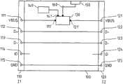
设备100包括:第一USB接口110(I1);第二USB接口120(I2);以及第一开关单元130,其耦合至第一USB接口110的VBUS111和第二USB接口120的VBUS 121。所述第一开关单元130配置用于:在第一状态中,将所述第一USB接口110的VBUS 111(也即,电源线)连接至所述第二USB接口120的VBUS 121(也即,电源线),并且所述第一开关单元130配置用于:将所述第一USB接口110的VBUS 111连接至第一附加电源线160,其中所述第一附加电源线160配置为例如由连接器150连接至第一电源。设备100还包括控制器140,其配置用于控制所述第一开关单元130。The
例如,所述设备100可以经由第一USB接口110连接至第一USB单元,并且所述设备100可以经由第二USB接口120连接至第二USB单元。如图1b中示例性描绘的,第一和第二USB单元可以经由D+和D-线来通信,其中D+和D-线连接至第一和第二接口110、120的相应D+管脚112、122和D-管脚113、123。此外,在所述第一开关单元130的第一状态中,第一USB单元可以从第二USB单元充电,这例如是在第一USB单元表示USB OTG B设备并且第二USB单元表示USB OTG A设备(例如,主机充电器)的情况下,或者反之亦然,第一USB单元可以为第二USB单元充电,这例如是在第一USB单元表示USB OTG A设备并且第二USB表示USB OTG B设备的情况下。在所述第一开关单元的第二状态中,第一USB单元可以从设备100的第一附加电源线160充电。例如,该设备可以包含位于连接器150与第一附加电源线160之间的内部充电器(图1中未示出)。For example, the
由此,按照本发明的设备100允许经由一个单独的USB连接器同时将第一USB单元连接至第二USB单元,并同时为第一USB单元充电。充电可以由设备100的内部电源来执行,或者由连接至第二接口120的第二USB单元来执行,这可以取决于连接至设备100的USB单元的类型。例如,任何应用数据传送期间的USB充电可以经由第一USB单元的单独USB连接器来执行。Thus, the
关于按照本发明的这些第一和第二示例性实施方式的阐释和优点对于后续示例性实施方式同样成立。因此,第一串行接口10的至少一个数据线12对应于第一USB接口110的D+管脚112和D-管脚113,并且第一串行接口10的电源线11对应于第一USB接口110的VBUS管脚111。对于第二串行接口20和第二USB接口120,至少一个数据线22对应于第二USB接口120的D+管脚122和D-管脚123,并且电源线21对应于第二USB接口120的VBUS管脚121。The explanations and advantages of these first and second exemplary embodiments according to the invention also hold true for the subsequent exemplary embodiments. Therefore, at least one
图1c中描绘了按照本发明的设备1、100的所述第一开关单元130的示例性实施方式的框图。此示例性第一开关单元130’包括三个开关S1、S2和S3,其中第三开关S3是可选的。在所述第一开关单元130’的第一状态期间,第一开关S1闭合,由此第一接口110的VBUS 111’连接至第二接口120的VBUS 121’,并且第二开关S2以及可选的第三开关S3可以打开。在所述第一开关单元130’的第二状态中,第二开关S2闭合,以便将第一附加电源线160连接至第一接口110的VBUS 111’,第一开关S1可以打开。此外,可选的开关S3可以闭合,以便将第二接口120的VBUS 121’连接至可选的第二附加电源线161。该可选的第二附加电源线可以连接至图1a、图1b中描绘的例如去往独立的第二电源的连接器150,从而为连接至第二接口120的第二USB单元供电。例如,第一附加电源线160可以连接至配置为连接至第一电源的内部充电器,以便为连接至第一接口110的第一USB单元充电。∏-阵列中的这三个开关S1、S2、S3提供了完全的OTG复本。经由连接器141,开关S1、S2、S3可以连接至控制器140。A block diagram of an exemplary embodiment of said first switching
可以按照如下方式来控制第一开关单元130,即,如果垂直的开关S2、S3之一闭合,则水平开关S1必须打开。这可以由连接至连接器160的控制器(例如,图1a、图1b中描绘的控制器140)来控制。例如,第一开关单元130还可以包括硬件单元,例如硬件门,以确保在潜在的软件崩溃的情况下不会出现错误状态。The
图2描绘了按照本发明的设备200的第三示例性实施方式的框图,其中该设备可以包括图1c中描绘的所述第一开关单元130’的示例性实施方式。第一附加电源线160连接至内部充电器285,并且第二附加电源线161连接至内部功率单元286,其中内部充电器285和内部功率单元286二者都连接至连接器250。第一开关单元130’的开关S1、S2、S3经由连接器141由控制器240来控制。Fig. 2 depicts a block diagram of a third exemplary embodiment of a
设备200还包括第二开关单元270,其分别耦合至第一和第二接口110、120的D+管脚112、122和D-管脚113、123,其中在第一状态中,所述第二开关单元将第一和第二USB接口110、120的D+管脚112、122彼此连接,并将第一和第二USB接口110、120的D-管脚113、123彼此连接,并且其中在第二状态中,所述第二开关单元禁用从第一USB接口110到第二USB接口120的数据通行。The
图3a描绘了按照本发明的设备200的所述第二开关单元270’的第一示例性实施方式的框图,其中所述第二开关单元270’包括三个开关D1、D2、D3,其每一个连接至连接器271,以便由控制器(例如,控制器240)来控制。在第二开关单元270’的所述第一状态中,开关D1和D3可以打开,并且双向开关D2可以闭合,而在所述第二状态中,开关D1和D3可以闭合,而双向开关D2可以打开,从而禁用数据通行。此外,该第二状态中D+和D-管脚之间的短路指示充电器。Fig. 3a depicts a block diagram of a first exemplary embodiment of said second switching unit 270' of a
图3b描绘了按照本发明的设备200的第二开关单元270”的第二示例性实施方式的框图,其中所述第二开关单元270’包括连接至连接器271的开关S4,以便由控制器(例如,控制器240)来控制。在第二开关单元270’的所述第一状态中,开关S4打开,以便允许数据通行,而在第二状态中,开关S4闭合,从而禁用数据通行。此外,该第二状态中D+和D-管脚之间的短路指示充电器。连接至D+和D-线的阻抗可以具有500Ω-1000Ω的DC阻抗,因而充电器检测系统仍将D+和D-解释为短路,并且可以使用这些阻抗(图3b中描绘的可能电阻器以及其他可能的滤波元件(例如,静电放电元件272、273)),从而使充电器信号发送系统不会对USB RF性能具有不良影响。Fig. 3b depicts a block diagram of a second exemplary embodiment of a
为了提供设备200的完全功能,连接至第一接口110的USB单元应当支持与设备200的通信,例如,以便发信号给所连接的USB单元。该通信可以经由第一接口110的ID管脚114来执行。按照USB标准,B插头的ID管脚是悬空的,并且A插头的ID管脚接地。由此,可以使用第一接口110的ID管脚114用于与兼容USB单元的数据通信,例如,通过将5线缆线连接至第一接口110,该第一接口110在其端部具有适于连接USB单元的USB插口的USB B插头。为了经由第一接口110的ID管脚114的这一通信,所述设备可以包括通信单元280,其可以连接至控制器240。经由ID管脚114的可能通信可由增强控制接口(ECI)链路来执行,其作为示例在图4和图5中描绘。将在关于图4和图5的相应实施方式的阐释中说明细节,其中这些细节对于图2中描绘的通信单元280同样成立。In order to provide full functionality of the
此外,例如,设备200可以配置用于经由第一USB接口110的ID管脚114来发射和/或接收射频(RF)信号。这例如可以用来经由设备200将来自附件的FM天线信号旁路到连接至第一USB接口110的USB单元。例如,第二USB接口120的ID管脚124可以借助于ID线而连接至第一USB接口的ID管脚114,并且所述FM天线信号可以经由第二USB接口120的ID管脚124从连接的附件通过设备的ID线而传输至第一USB接口110的ID管脚114。例如,可以借助于低通单元将通信单元280和/或检测单元290连接至所述ID线,从而使ID线上的RF信号不会干扰通信单元280和/或检测单元290。所述低通单元可以包括至少一个线圈。Additionally, for example,
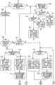
因此,设备200的功能将参考图9a/图9b中描绘的按照本发明的方法的示例性实施方式的流程图来加以阐释。Accordingly, the functionality of the
首先,设备可以确定连接至第一接口110(I1)的USB单元是否为兼容的单元,也即,配置用于经由第一接口110的ID管脚114与设备200通信的USB单元。该确定(步骤910)可以由通信单元280来执行。如果连接至第一接口110的USB单元不提供与设备200的通信,也即,表示不兼容的USB单元,则设备200可以仅提供有限的功能,例如只有充电,从而使第二开关单元270、270’、270”可以切换为第二状态(步骤920)。由此,不会有经由D+和D-线的数据通信,并且设备200经由D+和D-线来发信号给充电器。设备可以例如借助于检测单元290来检测充电器是否连接至第二接口,其中可以通过D+122高和D-123低以及VBUS 121供电来检测充电器。该检测可以在第二开关切换为第二状态(步骤920)之前执行。如果充电器连接至第二接口120(步骤921),则连接至第一接口110的USB单元可以从所连接的充电器进行充电,也即,控制器240将第一开关单元130’切换为第一状态(步骤921和923),或者连接至第一接口110的USB单元可以从第一附加电源线160充电,也即控制器240将第一开关单元130’切换为第二状态(步骤921和923)。如果没有充电器连接至第二接口120(I2)(步骤921),则控制器240可以直接将第一开关单元130’切换为第二状态(如果没有实现可选的双路充电模式),或者,如果存在双路充电模式,则在步骤922中确定双路充电是否已激活,如果已激活,则第一开关单元切换为第二状态的第一子状态(步骤924)。在第二状态的该第一子状态中,第一附加电源线160可以将第一接口110的VBUS 111连接至充电器285,以便为连接至第一接口110的USB单元充电,并且第二接口120的VBUS 121连接至第二附加电源线161,使得连接至第二USB接口的USB单元可以经由功率单元286来充电,其中功率单元286可以在双路充电模式中切换至充电器功能。如果没有激活双路充电,则在步骤925,第一开关单元130’切换为第二状态。激活双路充电模式可由双路充电按钮来执行,这显示了低成本实现和良好用户舒适度的有点,或者其例如可以基于软件控制而由控制器240来激活,这无需其他硬件成本。First, the device may determine whether the USB unit connected to the first interface 110 ( I1 ) is a compatible unit, ie, a USB unit configured to communicate with the
如果连接至第一接口110的USB单元被检测为兼容的单元(步骤910),则设备200可以提供完全功能。继而,连接至第二接口120的第二USB单元可以由检测单元290来检测(步骤930)。If the USB unit connected to the
继而,可以检查第二USB单元是否为USB OTG A设备(步骤935)。如果第二USB单元是A设备,并且如果该A设备表示主机充电器(host-charger)(步骤940),则第一开关单元130’切换为第一状态并且第二开关单元270切换为第一状态(步骤942)。如果第二USB单元是A设备但是不是主机充电器,则(步骤943)第一开关单元切换为第二状态,以便经由第一接口110来为第一USB单元充电,并且第二开关单元切换为第一状态,以便允许经由第一接口110和第二接口120的数据通行。此外,设备可以经由第一接口110的ID管脚114来发信号给连接至第一接口110的第一USB单元以通过该通信单元来禁用HNP&SRP(步骤944)。Then, it can be checked whether the second USB unit is a USB OTG A device (step 935). If the second USB unit is an A-device, and if the A-device represents a host-charger (step 940), the first switch unit 130' switches to the first state and the
如果没有USB OTG A设备连接至第二接口120(步骤935),则可以检查充电器是否连接至第二USB接口(步骤937),这例如由D+122高和D-123低表示,并且如果检测到充电器,则方法可以进行到步骤920或者可以直接跳转到步骤923。If no USB OTGA device is connected to the second interface 120 (step 935), it can be checked whether the charger is connected to the second USB interface (step 937), which is for example represented by D+122 high and D-123 low, and if If a charger is detected, the method may proceed to step 920 or may directly jump to step 923 .
如果没有检测到充电器连接至第二接口120(步骤937),并且如果实现了可选的双路充电模式,则首先检查双路充电是否打开(步骤950),如果双路充电激活,则(步骤951)第一开关单元切换为第二状态的第一子状态,并且第二开关单元切换为第二状态,以指示USB充电器。否则,如果双路充电没有打开或者如果没有实现可选的双路充电模式,则第一开关单元130’切换至第二状态,以便经由第一接口110为第一USB单元充电,并且第二开关单元270切换至第一状态,以便提供数据通行(步骤952),并且,例如如果检测到USB OTG B设备连接至第二接口,则设备可以发信号给连接至第一接口110的第一USB单元以切换为主机。If it is not detected that the charger is connected to the second interface 120 (step 937), and if the optional dual-way charging mode is implemented, first check whether the dual-way charging is turned on (step 950), if the dual-way charging is activated, then ( Step 951) The first switch unit is switched to the first sub-state of the second state, and the second switch unit is switched to the second state to indicate the USB charger. Otherwise, if the dual charging is not turned on or if the optional dual charging mode is not implemented, the first switch unit 130' switches to the second state to charge the first USB unit via the
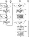
此外,如果第一电源在操作期间被移除,例如从连接器250断开,这分别可以在步骤945或者954中检测,则第一开关单元切换为第一状态(步骤946和955),以便将第一接口110的VBUS 111连接至第二接口的VBUS 121。如果第二USB单元是OTG A设备,则为连接至第一接口110的第一USB单元的供电由A设备提供(步骤946、955),如果第二USB单元不是OTG A设备,则经由通信单元280发信号给连接至第一接口110的第一USB单元以打开其电源,以便为连接至第二接口120的第二USB单元供电。Furthermore, if the first power source is removed during operation, for example disconnected from the
此外,如果检测到在操作期间移除的第一电源连接至设备200(步骤947和957),则第一开关单元130’切换为第二状态(步骤948和958),并且,如果第二USB单元不是OTG A设备,则经由通信单元280发信号给连接至第一接口110的第一USB单元以关闭其电源(步骤959)。Furthermore, if it is detected that the first power source removed during operation is connected to the device 200 (
可选地,设备200还可以包括附加开关,其配置用于将控制器240切换至第一或者第二USB接口110、120的VBUS 111、121,使得如果第一电源在操作期间被移除(步骤945、954),则该附加开关可以将控制器240连接至VBUS,以便得到功率。如果第一电源为设备200供电,则该附加开关打开,并且由此功率不会从外部VBUS去往控制单元240,以防止从外部VBUS获得过多电流。由此,在断电的情况下可以确保额外的鲁棒性。Optionally, the
此外,任何一次性检测(例如,在步骤930)可以通过多路复用来完成。这期待的是,充电被中断一段短时间,并在VBUS检测完成之后恢复。Additionally, any one-time detection (eg, at step 930) can be accomplished through multiplexing. What this expects is that charging is interrupted for a short period of time and resumes after the VBUS detection is complete.
而且,设备200还可以配置用于检测第一USB单元从第一USB接口110的断开(图9a和图9b中未示出),并且如果检测到断开,则设备200可以立即重置,并跳转到步骤910,以便等待USB单元连接至第一USB接口110。所述断开的检测可以由第一USB接口的ID管脚114来执行,例如借助于连续的ECI通信。Moreover, the
设备200还可以可选地包括可选OTG设备295,其连接至第二接口的VBUS 121,其中该OTG设备295表示泄漏开关电路,其配置用于切换为用于按照USB OTG标准的VBUS负载范围来补偿VBUS负载的状态。图5中描绘了此OTG设备295的示例性实施方式(“OTG扩展”)。The
图4描绘了按照本发明的设备400的另一示意性实施方式,其可以应用以取代前面阐述的设备。请注意,两个接口110、120的GND管脚115、125未在图4中示出。FIG. 4 depicts another schematic embodiment of a
设备400类似于图2中描绘的设备200,其中通信单元280可以利用TX和RX组件来实现,以便经由第一接口的ID管脚与连接至第一接口110的兼容USB单元405进行通信。例如,所述USB单元405可以表示移动电话,例如USB主机电话。USB单元405中的所述TX和RX组件以及ECI组件406可以与诺基亚制定的增强控制接口(ECI)链路相兼容。
ECI链路需要适当的机制以便按照规范兼容的方式开始与ID线的通信。为此目的,需要Hi-Z中断信号,并且其还是可用的专用检测电路,其被作为混合信号IC而集成在USB单元405中,否则可以使用与其他IC或者离散解决方案的集成。The ECI link requires a mechanism in place to initiate communication with the ID line in a specification compliant manner. For this purpose, a Hi-Z interrupt signal is required and also a dedicated detection circuit is available, integrated in the
当USB单元405检测到ID低状态时,其还将在不中断设备400的情况下启动特定数据模式。数据模式显示出低阻抗并且由图6中的LZ模式开关来设置。除了USB单元405控制之外,设备将自动地恢复Hi-Z模式。自动地强制切换是在所有插入和非插入情况中维护兼容性所需的。还具有到ECI的其他功能、作为数字电池接口(DBI)和签名连接器的USB单元405需要模式切换。When the
ECI接口通信和配置也可以由USB单元405来启动。在这种情况下,需要VBUS电压出现来开始通信询问,并且USB单元405需要设置低阻抗模式,因为通信阻抗需要约为1...2kΩ。如果没有响应,则可以确定连接的系统不包括ECI,并且可以中止通信模式。通信可以期望设备400由连接器(例如,图2中描绘的连接器250)来供电。该方法避免了USB单元405中的Hi-Z检测,同时该方法可以基于中断来检测所有设备。ECI链路可以是菊花链式的,如图5中所描绘的,但是这给硬件和软件带来了额外的复杂度。ECI interface communication and configuration can also be initiated by the
图5描绘了按照本发明的设备的示例性控制链路和示例性控制级的框图,其中所述设备可以是上述任何设备。该控制链路包括经由检测单元290’对第二接口的ID管脚124状态的检测。例如,所述检测单元290’可以是图2中描绘的检测单元290的一部分。例如,对ID管脚124状态的检测可以用来检测A设备或者B设备是否连接至第二接口120。此外,如果连接至第二接口124的第二USB单元被移除,则比较器可以触发以及可以给出对控制器的信号,控制器可以重置设备200、400。Figure 5 depicts a block diagram of an exemplary control link and exemplary control stages of a device according to the invention, wherein said device may be any of the devices described above. The control chain includes detection of the state of the
图6描绘了按照本发明的设备的示例性开关布置的框图,其包括与第一开关单元相关联的三个开关S1、S2、S3,并且包括第二开关单元270”的实施方式。图6给出了两种不同的开关布置情况。默认的安全控制硬件由逻辑门给出。控制系统可以在开机时重置,使得所有控制线为低。Figure 6 depicts a block diagram of an exemplary switch arrangement of a device according to the invention comprising three switches S1, S2, S3 associated with a first switch unit and comprising an embodiment of a
静电放电(ESD)保护连接至连接器VBUS 111、121以及ID管脚114、124二者(参见图5)。Electrostatic discharge (ESD) protection is connected to both
此外,当应用在USB单元上运行的同时从电池供电、并且设备100、200、400连接至充电器但是未由其供电时,则切换在功率递送中创建中断。如果现在需要充电,则转变(switch-over)将终止运行的应用,这可能为用户带来问题。在这种情况下,可以在需要来自充电器的特殊控制性能的设备100、200、400中布置交接(handover)系统。可以通过对设备的调节器(regulator)的电压控制回路布置来控制设备和VBUS交接,使得在交接过程中将不会发生任何电压瞬变。交接可以在两个方向中完成,直到电源打开。经由ECI通信系统(例如,图6中描述的)的交接切换控制延迟在几十毫秒的范围内。该交接系统可以是可选的。Furthermore, when an application is running on the USB unit while being powered from the battery and the
图7描绘了按照本发明实施方式的系统的另一示例性实施方式的框图,其中仅示出了USB接口110、120的数据线D+和D-。第一接口110可以表示B插头,而第二接口120可以表示AB插口。USB单元720表示PC或者主机充电器,USB单元730表示分立充电器,并且USB单元74表示B设备,每个都适于连接至按照本发明的设备700的第二接口120。USB单元710表示“主机”移动系统。所述设备可以是上述任何设备。Fig. 7 depicts a block diagram of another exemplary embodiment of a system according to an embodiment of the present invention, wherein only the data lines D+ and D- of the USB interfaces 110, 120 are shown. The
此外,例如,设备100、200、400对于外部充电器标识系统而言可以是透明的,其中D+和D-的作用例如可以交换。Furthermore, for example, the
图8描绘了按照本发明实施方式的系统的另一示例性实施方式的框图。设备820对应于图7中描绘的设备700,并且“主机”移动系统810对应于图7中描绘的USB单元710。表示为“连接的”移动系统830(包括AB连接器)的另一移动系统可以由AB缆线或者BA缆线备选地连接至第二接口120,其中在第一情况中,“连接的”移动系统起到B设备的初始作用,并且在第二情况中,起到A设备的初始作用。Figure 8 depicts a block diagram of another exemplary embodiment of a system in accordance with an embodiment of the present invention.
图10描绘了按照本发明实施方式的系统的另一示例性实施方式的框图,其中设备1000的示例性实施方式可以包括连接至第二接口120的USB微型AB插口,以及终止于微型B插头1010的5线缆线,所述5线缆线连接至第一接口110。设备1000还可以可选地包括双路充电按钮。该设备可以由连接至第一电源的干线电源1030供电。例如,所述设备1000可以包括去往干线电源/连接器1030的长供电导线,使得设备可以位于远离干线电源1030处。设备1000的设计可以是这样的:与设备1000的USB连接可以物理上与干线插座隔开一定距离。外围设备可以通过微型AB插口1020连接至该设备。这将采用微型A或者微型B插头,按照USB OTG规则,其还确定第一USB单元1100的初始作用。图10中示出了可以连接的设备类型的示例:在任一配置中连接的膝上型计算机/PC 1500、USB充电器1400、USB耳机1300、或者其他USB单元1200,例如终端或者移动电话等。10 depicts a block diagram of another exemplary embodiment of a system according to an embodiment of the present invention, wherein an exemplary embodiment of a
此外,上述设备1、100、200、400、1000中的任何设备可以包括连接至第一USB接口110的插头1010,其中该插头1010可以来自以下之一:标准B插头、迷你B插头、微型B插头、自产(captive)(也即,专有)或者硬线自产(也即,不可移动),并且设备100、200、400、1000中的任何设备可以包括连接至第二USB接口120的插口1020,其中该插口1020来自以下之一:迷你AB、微型AB或者标准A/迷你A插头加B侧连接器之一的组合。Furthermore, any of the
上文借助于示例性实施方式描述了本发明。应当注意,存在备选方案以及变形,其对于本领域技术人员而言是显而易见的,并且可以在不脱离所附权利要求书的范围和精神的情况下加以实现。The invention has been described above by means of exemplary embodiments. It should be noted that there are alternatives and modifications, which are obvious to those skilled in the art and which can be made without departing from the scope and spirit of the appended claims.
Claims (16)
Translated fromChineseApplications Claiming Priority (1)
| Application Number | Priority Date | Filing Date | Title |
|---|---|---|---|
| PCT/IB2006/054694WO2008068552A1 (en) | 2006-12-08 | 2006-12-08 | Multiple connections to a single serial interface |
Publications (2)
| Publication Number | Publication Date |
|---|---|
| CN101601001A CN101601001A (en) | 2009-12-09 |
| CN101601001Btrue CN101601001B (en) | 2012-07-18 |
Family
ID=38267658
Family Applications (1)
| Application Number | Title | Priority Date | Filing Date |
|---|---|---|---|
| CN200680056905.4AExpired - Fee RelatedCN101601001B (en) | 2006-12-08 | 2006-12-08 | Multiple connections to separate serial interfaces |
Country Status (4)
| Country | Link |
|---|---|
| US (1) | US8898363B2 (en) |
| EP (2) | EP2092407B1 (en) |
| CN (1) | CN101601001B (en) |
| WO (1) | WO2008068552A1 (en) |
Families Citing this family (50)
| Publication number | Priority date | Publication date | Assignee | Title |
|---|---|---|---|---|
| CN101601001B (en)* | 2006-12-08 | 2012-07-18 | 诺基亚公司 | Multiple connections to separate serial interfaces |
| US8194893B1 (en)* | 2007-09-28 | 2012-06-05 | Lewis Peter G | Wired in-ear monitor system |
| WO2009062551A1 (en)* | 2007-11-15 | 2009-05-22 | Nokia Corporation | Power connection between serial interfaces |
| CN101789087B (en)* | 2010-01-08 | 2012-12-12 | 福州瑞芯微电子有限公司 | Equipment with contact type IC (Integrated Circuit) card slot and contact type IC protective circuit |
| US8717044B2 (en)* | 2010-04-23 | 2014-05-06 | Apple Inc. | Charging systems with direct charging port support and extended capabilities |
| US8826051B2 (en)* | 2010-07-26 | 2014-09-02 | Apple Inc. | Dynamic allocation of power budget to a system having non-volatile memory and a processor |
| JP5799852B2 (en)* | 2011-03-30 | 2015-10-28 | ソニー株式会社 | Input/Output Devices |
| US9395780B2 (en)* | 2011-04-21 | 2016-07-19 | Texas Instruments Incorporated | USB bridge circuit gating RID—A and RID—GND for IDGND |
| MY169836A (en) | 2011-12-06 | 2019-05-16 | Intel Corp | Techniques for serial interface charging |
| JP5803896B2 (en)* | 2012-02-23 | 2015-11-04 | ソニー株式会社 | Input/Output Devices |
| CN102629772A (en)* | 2012-04-05 | 2012-08-08 | 福兴达科技实业(深圳)有限公司 | Mobile terminal and charging method of mobile terminal |
| US8732366B2 (en)* | 2012-04-30 | 2014-05-20 | Freescale Semiconductor, Inc. | Method to configure serial communications and device thereof |
| KR101920236B1 (en) | 2012-06-19 | 2018-11-20 | 삼성전자주식회사 | Method for charging battery and an electronic device thereof |
| US9268728B2 (en)* | 2012-07-02 | 2016-02-23 | Htc Corporation | Portable electronic device and accessory device thereof, and operating method for the portable electronic device |
| KR102158288B1 (en)* | 2012-07-09 | 2020-09-21 | 삼성전자주식회사 | Method for charging battery and an electronic device thereof |
| US9858236B2 (en) | 2012-12-04 | 2018-01-02 | Nokia Technologies Oy | Serial protocol over data interface |
| EP2755109B1 (en)* | 2013-01-09 | 2016-03-16 | Sony Mobile Communications AB | Charging an electrical device via a data interface |
| US8930586B2 (en)* | 2013-04-03 | 2015-01-06 | Lenovo Enterprise Solutions (Singapore) Pte. Ltd. | Identification of electronic devices operating within a computing system |
| CN104239240A (en)* | 2013-06-11 | 2014-12-24 | 鸿富锦精密工业(深圳)有限公司 | Electronic device with universal serial bus (USB) interface with integration function |
| KR102136068B1 (en)* | 2013-07-04 | 2020-07-21 | 삼성전자 주식회사 | Control method for usb interface and electronic device supporting the same |
| TWI507873B (en)* | 2013-07-29 | 2015-11-11 | Hon Hai Prec Ind Co Ltd | Power adapter and electronic device |
| CN103561369B (en)* | 2013-10-31 | 2017-05-17 | 惠州Tcl移动通信有限公司 | Usb interface circuit and electronic equipment |
| US9583975B2 (en)* | 2014-02-07 | 2017-02-28 | Nokia Technologies Oy | Charging and audio usage |
| US9507398B2 (en)* | 2014-02-28 | 2016-11-29 | Infineon Technologies Austria Ag | Communication over identification line |
| US9772653B2 (en)* | 2014-05-22 | 2017-09-26 | Via Technologies, Inc. | Mechanism for charging portable device with USB dock |
| CN104932615B (en)* | 2014-05-22 | 2019-03-05 | 威盛电子股份有限公司 | Universal serial bus expansion seat and method for charging portable device by using same |
| US9588560B2 (en) | 2014-05-28 | 2017-03-07 | Nokia Technologies Oy | Baseband PD communication over USB standard a connector |
| JP5986145B2 (en)* | 2014-07-02 | 2016-09-06 | レノボ・シンガポール・プライベート・リミテッド | Portable devices, cable assemblies and USB systems |
| WO2016011400A1 (en)* | 2014-07-17 | 2016-01-21 | SparqEE Technologies, L.L.C. | Automatically adjustable, charge-only, usb adapter |
| CN105677596B (en)* | 2014-11-21 | 2021-09-14 | 联想(北京)有限公司 | Control method and electronic equipment |
| CN106200442B (en)* | 2015-04-30 | 2021-04-09 | 中兴通讯股份有限公司 | Method and device for realizing connection control |
| US10564697B2 (en)* | 2015-05-25 | 2020-02-18 | Huawei Technologies Co., Ltd. | OTG peripheral, power supply method, terminal and system |
| US10394743B2 (en)* | 2015-05-28 | 2019-08-27 | Dell Products, L.P. | Interchangeable I/O modules with individual and shared personalities |
| US20160365853A1 (en)* | 2015-06-09 | 2016-12-15 | Magna Closures Inc. | Electromechanical switch via wiring connector |
| KR102391100B1 (en) | 2015-06-10 | 2022-04-27 | 삼성전자주식회사 | Method and apparatus for providing interface |
| CN106532795A (en)* | 2015-09-15 | 2017-03-22 | 中兴通讯股份有限公司 | Terminal usb interface setting method and terminal |
| CN105116988B (en)* | 2015-09-16 | 2019-02-05 | 联想(北京)有限公司 | A kind of electronic equipment |
| CN107085558B (en)* | 2016-03-28 | 2020-12-04 | 曹巍 | Adapter for connecting A-type USB and C-type USB equipment |
| EP3479195B1 (en)* | 2016-06-29 | 2020-11-18 | Square, Inc. | Usb interface and switching |
| US10409755B2 (en)* | 2016-06-29 | 2019-09-10 | Square, Inc. | Multi-mode USB interface |
| US9710037B1 (en)* | 2016-06-29 | 2017-07-18 | Square, Inc. | USB voltage regulation and switching |
| US10740740B1 (en) | 2016-06-29 | 2020-08-11 | Square, Inc. | Monitoring and recovery for a USB interface |
| EP3484002B1 (en)* | 2016-07-26 | 2021-09-01 | Huawei Technologies Co., Ltd. | Electrostatic protection circuit |
| KR102576929B1 (en)* | 2016-07-29 | 2023-09-12 | 삼성전자주식회사 | Electrical device |
| CN106208260B (en)* | 2016-08-31 | 2018-12-04 | 维沃移动通信有限公司 | A kind of charging circuit, data line and charging interface |
| KR102575430B1 (en) | 2016-10-25 | 2023-09-06 | 삼성전자 주식회사 | Electronic device and method for recognizing connected terminals of external device thereof |
| CN107733025B (en)* | 2017-10-30 | 2023-11-21 | 深圳市亿道数码技术有限公司 | USB and DC compatible double-charging circuit and operation method thereof |
| CN112994161A (en)* | 2020-05-28 | 2021-06-18 | 上海闻泰电子科技有限公司 | Terminal and charger |
| EP3933603B1 (en)* | 2020-07-02 | 2024-08-28 | Infineon Technologies AG | An electrostatic discharge, esd, protection device for a universal serial bus, usb, interface |
| CN120277016B (en)* | 2025-06-10 | 2025-09-05 | 深圳市信步科技有限公司 | Dynamic expansion control method, device and storage medium for motherboard interface device |
Citations (3)
| Publication number | Priority date | Publication date | Assignee | Title |
|---|---|---|---|---|
| US6253329B1 (en)* | 1998-01-16 | 2001-06-26 | Samsung Electronics Co., Ltd. | Universal serial bus (USB) hub having a plurality of input power sources |
| EP1487081A2 (en)* | 2003-06-11 | 2004-12-15 | Research In Motion Limited | Universal serial bus (USB) charger for a mobile device |
| CN1581121A (en)* | 2003-08-09 | 2005-02-16 | 深圳市朗科科技有限公司 | Semicondustor storage device having host system operation function |
Family Cites Families (26)
| Publication number | Priority date | Publication date | Assignee | Title |
|---|---|---|---|---|
| JPH11275757A (en)* | 1998-03-19 | 1999-10-08 | Fuji Electric Co Ltd | Power supply |
| US6279060B1 (en)* | 1998-12-04 | 2001-08-21 | In-System Design, Inc. | Universal serial bus peripheral bridge simulates a device disconnect condition to a host when the device is in a not-ready condition to avoid wasting bus resources |
| JP2000316006A (en)* | 1999-04-28 | 2000-11-14 | Nec Corp | Node having provision for bus manager function automatic changeover, mobile terminal and mobile terminal system |
| CN1222891C (en)* | 1999-12-24 | 2005-10-12 | 皇家菲利浦电子有限公司 | Method and system for simulating disconnection of a device from a wired segment |
| US20020154060A1 (en)* | 2001-04-18 | 2002-10-24 | Axiom Navigation, Inc. | System and method for providing worldwide seamless location coverage |
| DE10126947C2 (en)* | 2001-06-01 | 2003-06-26 | Deutsch Zentr Luft & Raumfahrt | Data transmission system with a local beacon |
| JP3558059B2 (en)* | 2001-08-10 | 2004-08-25 | セイコーエプソン株式会社 | Power supply control circuit and electronic equipment |
| EP1330074B1 (en)* | 2002-01-21 | 2005-12-28 | Hewlett-Packard Company | Location device of data network appliance |
| EP1588506A4 (en)* | 2003-01-15 | 2007-03-14 | Symbol Technologies Inc | WIRELESS ACCENT POINTS OF LUMINAIRES |
| TW587891U (en)* | 2003-02-27 | 2004-05-11 | Lite On Technology Corp | Name card scanner |
| GB2402271B (en)* | 2003-05-27 | 2006-04-19 | Research In Motion Ltd | Method and apparatus for handling a charging state in a mobile electronic device |
| US7324824B2 (en)* | 2003-12-09 | 2008-01-29 | Awarepoint Corporation | Wireless network monitoring system |
| US7271568B2 (en)* | 2004-02-11 | 2007-09-18 | Research In Motion Limited | Battery charger for portable devices and related methods |
| CN2739695Y (en) | 2004-05-18 | 2005-11-09 | 华为技术有限公司 | Portable electronic device and its charging device charging interface and expanding head |
| JP5016783B2 (en)* | 2004-08-11 | 2012-09-05 | 株式会社東芝 | Information processing apparatus and power supply control method thereof |
| TW200513865A (en)* | 2004-09-17 | 2005-04-16 | Via Tech Inc | USB control circuit with function of switching between host mode and controlled mode and its operating method |
| US7310697B2 (en)* | 2004-11-01 | 2007-12-18 | Hewlett-Packard Development Company, L.P. | System and method for dynamic USB power source |
| TWI253226B (en)* | 2004-12-31 | 2006-04-11 | Ali Corp | Battery charging set and method for portable equipment with On-The-Go function |
| US7679317B2 (en)* | 2005-02-15 | 2010-03-16 | Research In Motion Limited | Systems and methods for charging a chargeable USB device |
| DE602005023259D1 (en)* | 2005-02-15 | 2010-10-14 | Research In Motion Ltd | Method and device for charging a rechargeable USB device |
| TWI280710B (en)* | 2005-03-04 | 2007-05-01 | Behavior Tech Computer Corp | Two-way electrical device with USB interface |
| KR100653065B1 (en)* | 2005-07-21 | 2006-12-01 | 삼성전자주식회사 | Electronic system and control method |
| KR100748554B1 (en)* | 2005-07-26 | 2007-08-10 | 삼성전자주식회사 | Universal serial bus host, universal serial bus system and how to drive it |
| US7624202B2 (en)* | 2006-08-17 | 2009-11-24 | Standard Microsystems Corporation | System and method for enumerating a USB device using low power |
| CN101601001B (en)* | 2006-12-08 | 2012-07-18 | 诺基亚公司 | Multiple connections to separate serial interfaces |
| US7949802B2 (en)* | 2006-12-08 | 2011-05-24 | Nokia Corporation | Enhanced communication via a serial interface |
- 2006
- 2006-12-08CNCN200680056905.4Apatent/CN101601001B/ennot_activeExpired - Fee Related
- 2006-12-08WOPCT/IB2006/054694patent/WO2008068552A1/enactiveApplication Filing
- 2006-12-08EPEP06832167Apatent/EP2092407B1/ennot_activeNot-in-force
- 2006-12-08EPEP12170031.4Apatent/EP2498167B1/ennot_activeNot-in-force
- 2006-12-08USUS12/517,780patent/US8898363B2/ennot_activeExpired - Fee Related
Patent Citations (3)
| Publication number | Priority date | Publication date | Assignee | Title |
|---|---|---|---|---|
| US6253329B1 (en)* | 1998-01-16 | 2001-06-26 | Samsung Electronics Co., Ltd. | Universal serial bus (USB) hub having a plurality of input power sources |
| EP1487081A2 (en)* | 2003-06-11 | 2004-12-15 | Research In Motion Limited | Universal serial bus (USB) charger for a mobile device |
| CN1581121A (en)* | 2003-08-09 | 2005-02-16 | 深圳市朗科科技有限公司 | Semicondustor storage device having host system operation function |
Also Published As
| Publication number | Publication date |
|---|---|
| EP2498167B1 (en) | 2013-10-02 |
| EP2498167A1 (en) | 2012-09-12 |
| CN101601001A (en) | 2009-12-09 |
| US8898363B2 (en) | 2014-11-25 |
| EP2092407A1 (en) | 2009-08-26 |
| US20100169534A1 (en) | 2010-07-01 |
| WO2008068552A1 (en) | 2008-06-12 |
| EP2092407B1 (en) | 2013-01-23 |
Similar Documents
| Publication | Publication Date | Title |
|---|---|---|
| CN101601001B (en) | Multiple connections to separate serial interfaces | |
| TWI648635B (en) | Universal serial bus hub and operation method thereof | |
| JP6173297B2 (en) | Mobile terminal and interface method thereof | |
| US9418032B2 (en) | Adaptive accessory detection and mode negotiation | |
| CN104081368B (en) | Mobile device automatic detection device and method | |
| CN101359316B (en) | Method and apparatus for implementing general-purpose serial bus USB OTG | |
| CN110829523B (en) | Electronic equipment and reverse charging method | |
| AU2008243700B2 (en) | A docking station | |
| US9772653B2 (en) | Mechanism for charging portable device with USB dock | |
| CN101534349A (en) | Method and apparatus for determining external connection device in mobile terminal | |
| US20080140887A1 (en) | Enhanced communication via a serial interface | |
| WO2018176901A1 (en) | Adapter, terminal device and adapter system | |
| CN110247264B (en) | Connector and method for controlling charging by using connector | |
| US8458376B1 (en) | USB peripheral device with automatic mode switch | |
| CN101498756B (en) | Discrimination method and apparatus for external device connected with portable terminal set | |
| CN111725858A (en) | A power adapter and charging method | |
| KR20160143077A (en) | Electronic apparatus and method for controlling power supply of the same | |
| CN115237841A (en) | Electronic device, fast charging method, device, system and readable storage medium | |
| KR102672130B1 (en) | A method and an electronic device powered by an external device | |
| US20120096286A1 (en) | Charging management method, charging control circuit and the host apparatus having the same | |
| CN106797414A (en) | A terminal leakage current detection circuit and terminal | |
| CN109346883A (en) | A kind of system for realizing the positive anti-plug of Type-C interface | |
| TW201814543A (en) | Apparatus and method for USB charge and communication | |
| CN101685934A (en) | Pluggable adapter and portable system | |
| TWI829240B (en) | Electronic device |
Legal Events
| Date | Code | Title | Description |
|---|---|---|---|
| C06 | Publication | ||
| PB01 | Publication | ||
| C10 | Entry into substantive examination | ||
| SE01 | Entry into force of request for substantive examination | ||
| C14 | Grant of patent or utility model | ||
| GR01 | Patent grant | ||
| C41 | Transfer of patent application or patent right or utility model | ||
| TR01 | Transfer of patent right | Effective date of registration:20160118 Address after:Espoo, Finland Patentee after:Technology Co., Ltd. of Nokia Address before:Espoo, Finland Patentee before:Nokia Oyj | |
| CF01 | Termination of patent right due to non-payment of annual fee | ||
| CF01 | Termination of patent right due to non-payment of annual fee | Granted publication date:20120718 Termination date:20201208 |