CN101600140B - Sound producing device - Google Patents
Sound producing deviceDownload PDFInfo
- Publication number
- CN101600140B CN101600140BCN 200810067589CN200810067589ACN101600140BCN 101600140 BCN101600140 BCN 101600140BCN 200810067589CN200810067589CN 200810067589CN 200810067589 ACN200810067589 ACN 200810067589ACN 101600140 BCN101600140 BCN 101600140B
- Authority
- CN
- China
- Prior art keywords
- sound
- carbon nanotube
- generating device
- carbon nanotubes
- signal input
- Prior art date
- Legal status (The legal status is an assumption and is not a legal conclusion. Google has not performed a legal analysis and makes no representation as to the accuracy of the status listed.)
- Active
Links
Images


Landscapes
- Electrostatic, Electromagnetic, Magneto- Strictive, And Variable-Resistance Transducers (AREA)
- Carbon And Carbon Compounds (AREA)
- Details Of Audible-Bandwidth Transducers (AREA)
Abstract
Description
Translated fromChinese技术领域technical field
本发明涉及一种发声装置,尤其涉及一种基于碳纳米管的发声装置。The invention relates to a sounding device, in particular to a sounding device based on carbon nanotubes.
背景技术Background technique
发声装置一般由信号输入装置和发声元件组成。通过信号输入装置输入电信号给发声元件,进而发出声音。现有技术中的发声元件一般为一扬声器。该扬声器为一种把电信号转换成声音信号的电声器件。具体地,扬声器可将一定范围内的音频电功率信号通过换能方式转变为失真小并具有足够声压级的可听声音。The sounding device generally consists of a signal input device and a sounding element. The electrical signal is input to the sound generating element through the signal input device, and then the sound is emitted. The sound emitting element in the prior art is generally a loudspeaker. The loudspeaker is an electro-acoustic device that converts electrical signals into sound signals. Specifically, the speaker can convert audio electric power signals within a certain range into audible sounds with less distortion and sufficient sound pressure level.
现有的扬声器的种类很多,根据其工作原理,分为:电动式扬声器、电磁式扬声器、静电式扬声器及压电式扬声器。虽然它们的工作方式不同,但一般均为通过产生机械振动推动周围的空气,使空气介质产生波动从而实现“电-力-声”之转换。其中,电动式扬声器的应用最为广泛。There are many kinds of existing loudspeakers, which can be divided into electrodynamic loudspeakers, electromagnetic loudspeakers, electrostatic loudspeakers and piezoelectric loudspeakers according to their working principles. Although they work in different ways, they generally push the surrounding air by generating mechanical vibrations, causing the air medium to fluctuate so as to realize the conversion of "electricity-force-acoustic". Among them, the dynamic speaker is the most widely used.
请参阅图1,现有的电动式扬声器100通常由三部分组成:音圈102、磁铁104以及振膜106。音圈102通常采用通电导体,当音圈102中输入一个音频电流信号时,音圈102相当于一个载流导体。由于放在所述磁铁104产生的磁场里,根据载流导体在磁场中会受到洛仑兹力,音圈102会受到一个大小与音频电流成正比、方向随音频电流方向的变化而变化的力。因此,音圈102就会在所述磁铁104产生的磁场作用下产生振动,并带动振膜106振动,振膜106前后的空气亦随之振动,将电信号转换成声波向四周辐射。然而,该电动式扬声器100的结构较为复杂,且其必须在有磁的条件下工作。Please refer to FIG. 1 , the conventional
自九十年代初以来,以碳纳米管(请参见Helical microtubules of graphiticcarbon,Nature,Sumio Iijima,vol 354,p56(1991))为代表的纳米材料以其独特的结构和性质引起了人们极大的关注。近几年来,随着碳纳米管及纳米材料研究的不断深入,其广阔的应用前景不断显现出来。例如,由于碳纳米管所具有的独特的电磁学、光学、力学、化学等性能,大量有关其在场发射电子源、传感器、新型光学材料、软铁磁材料等领域的应用研究不断被报道。然而,现有技术中却尚未发现碳纳米管用于发声领域。Since the early 1990s, nanomaterials represented by carbon nanotubes (see Helical microtubules of graphiticcarbon, Nature, Sumio Iijima, vol 354, p56 (1991)) have attracted great attention for their unique structures and properties. focus on. In recent years, with the continuous deepening of research on carbon nanotubes and nanomaterials, their broad application prospects continue to emerge. For example, due to the unique electromagnetic, optical, mechanical, and chemical properties of carbon nanotubes, a large number of applications in the fields of field emission electron sources, sensors, new optical materials, and soft ferromagnetic materials have been continuously reported. However, carbon nanotubes have not been found to be used in the field of sound generation in the prior art.
因此,确有必要提供一种发声装置,该发声装置结构简单,可在无磁的条件下工作。Therefore, it is really necessary to provide a sounding device, which has a simple structure and can work under non-magnetic conditions.
发明内容Contents of the invention
一种发声装置,其包括:一信号输入装置;以及一发声元件,该发声元件与所述信号输入装置的两端电连接;其中,所述发声元件包括至少一层碳纳米管薄膜,该碳纳米管薄膜包括多个相互平行的碳纳米管,所述信号输入装置输入电信号给该发声元件,使该发声元件加热周围气体介质发出声波。A sounding device, which includes: a signal input device; and a sounding element, the sounding element is electrically connected to both ends of the signal inputting device; wherein, the sounding element includes at least one layer of carbon nanotube film, the carbon The nanotube film includes a plurality of carbon nanotubes parallel to each other, and the signal input device inputs electric signals to the sounding element, so that the sounding element heats the surrounding gas medium to emit sound waves.
与现有技术相比较,所述发声装置具有以下优点:其一,由于所述发声装置中的发声元件仅包括碳纳米管薄膜,无需磁铁等其它复杂结构,故该发声装置的结构较为简单,有利于降低该发声装置的成本。其二,该发声装置利用输入信号造成该发声元件温度变化,从而使其周围气体介质迅速膨胀和收缩,进而发出声波,无需振膜,且该发声元件组成的发声装置可在无磁的条件下工作。其三,由于碳纳米管薄膜具有较小的热容和大的比表面积,且碳纳米管薄膜中的碳纳米管相互平行、均匀分布,在输入信号后,根据信号强度(如电流强度)的变化,由至少一层碳纳米管薄膜组成的发声元件可均匀地加热周围的气体介质、迅速升降温、产生周期性的温度变化,并和周围气体介质进行快速热交换,使周围气体介质迅速膨胀和收缩,发出人耳可感知的声音,且所发出的声音的频率范围较宽(1Hz~100kHz)、发声效果较好。另外,当该发声元件厚度比较小时,例如小于10微米,该发声元件具有较高的透明度,故所形成的发声装置为透明发声装置,可以直接安装在各种显示装置、手机显示屏的显示表面或油画显示装置、油画等的表面作为节省空间的透明发声装置。其四,由于碳纳米管具有较好的机械强度和韧性,故由相互平行的碳纳米管组成的至少一层碳纳米管薄膜具有较好的机械强度和韧性,耐用性较好,从而有利于制备由碳纳米管薄膜组成的各种形状、尺寸的发声装置,进而方便地应用于各种领域。Compared with the prior art, the sound generating device has the following advantages: one, because the sound emitting device in the sound generating device only includes carbon nanotube thin films, and does not need other complex structures such as magnets, the structure of the sound generating device is relatively simple, It is beneficial to reduce the cost of the sound generating device. Second, the sounding device uses the input signal to cause the temperature of the sounding element to change, so that the gas medium around it expands and contracts rapidly, and then emits sound waves without a diaphragm, and the sounding device composed of the sounding element can operate under non-magnetic conditions. Work. Third, since the carbon nanotube film has a small heat capacity and a large specific surface area, and the carbon nanotubes in the carbon nanotube film are parallel to each other and uniformly distributed, after the input signal, according to the signal intensity (such as current intensity) The sound-generating element composed of at least one layer of carbon nanotube film can evenly heat the surrounding gas medium, rapidly raise and lower the temperature, produce periodic temperature changes, and conduct rapid heat exchange with the surrounding gas medium, so that the surrounding gas medium expands rapidly And contraction, it emits a sound that can be perceived by the human ear, and the frequency range of the emitted sound is wide (1Hz-100kHz), and the sound effect is better. In addition, when the thickness of the sounding element is relatively small, such as less than 10 microns, the sounding element has high transparency, so the formed sounding device is a transparent sounding device, which can be directly installed on the display surface of various display devices and mobile phone display screens Or the surface of an oil painting display device, oil painting, etc. as a space-saving transparent sounding device. Fourth, because carbon nanotubes have good mechanical strength and toughness, at least one layer of carbon nanotube film composed of carbon nanotubes parallel to each other has good mechanical strength and toughness, and good durability, which is beneficial to Sound generating devices of various shapes and sizes composed of carbon nanotube films are prepared, and then conveniently applied in various fields.
附图说明Description of drawings
图1是现有技术中扬声器的结构示意图。Fig. 1 is a schematic structural diagram of a loudspeaker in the prior art.
图2是本技术方案第一实施例发声装置的结构示意图。Fig. 2 is a schematic structural diagram of the sound generating device according to the first embodiment of the technical solution.
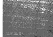
图3是本技术方案第一实施例发声装置中碳纳米管薄膜的扫描电镜照片。Fig. 3 is a scanning electron micrograph of the carbon nanotube thin film in the sound generating device of the first embodiment of the technical solution.
图4是本技术方案第二实施例发声装置的结构示意图。Fig. 4 is a schematic structural diagram of a sound generating device according to a second embodiment of the technical solution.
具体实施方式Detailed ways
以下将结合附图详细说明本技术方案实施例的发声装置。The sound generating device of the embodiment of the technical solution will be described in detail below with reference to the accompanying drawings.
请参阅图2,本技术方案第一实施例提供一种发声装置10,该发声装置10包括一信号输入装置12,一发声元件14,一第一电极142以及一第二电极144。所述第一电极142和第二电极144间隔设置,且与所述发声元件14电连接。所述第一电极142和第二电极144可起到支撑所述发声元件14的作用。另外,所述第一电极142和第二电极144分别通过外接导线149与所述信号输入装置12的两端电连接,用于将所述信号输入装置12中的信号输入到所述发声元件14中。Please refer to FIG. 2 , the first embodiment of the technical solution provides a
所述发声元件14包括至少一层碳纳米管薄膜。请参见图3,所述碳纳米管薄膜包括多个相互平行的碳纳米管。相邻两个碳纳米管之间通过范德华力紧密结合。所述碳纳米管薄膜中的相邻两个碳纳米管之间的距离小于50微米。所述碳纳米管薄膜的长度为碳纳米管薄膜中单根碳纳米管的长度。所述碳纳米管薄膜的宽度不限。所述碳纳米管薄膜的厚度为0.5纳米~100微米。所述碳纳米管薄膜的长度为1微米~30毫米。进一步地,所述发声元件14包括至少两层重叠设置的碳纳米管薄膜,相邻两层碳纳米管薄膜之间通过范德华力紧密结合,且相邻两层碳纳米管薄膜中的碳纳米管之间具有一交叉角度α,α大于等于0度且小于等于90度,具体可依据实际需求制备。当相邻两层碳纳米管薄膜中的碳纳米管之间的夹角α大于0度时,所述发声元件14中的多个碳纳米管形成一网状结构,且该网状结构包括多个均匀分布的微孔,其孔径为小于50微米。当所述发声元件14包括多层碳纳米管薄膜时,由于相邻两层碳纳米管薄膜之间通过范德华力紧密结合,故所述发声元件14具有很好的自支撑性能。所述碳纳米管薄膜中的碳纳米管可为单壁碳纳米管、双壁碳纳米管及多壁碳纳米管中的一种或多种。所述单壁碳纳米管的直径为0.5纳米~50纳米,所述双壁碳纳米管的直径为1.0纳米~50纳米,所述多壁碳纳米管的直径为1.5纳米~50纳米。所述发声元件14的厚度为0.5纳米~1毫米。当该发声元件14的厚度比较小时,例如小于10微米,该发声元件14具有较高的透明度,故采用该发声元件14的发声装置10为透明发声装置10,可以直接安装在各种显示装置、手机显示屏的显示表面或油画的表面作为节省空间的透明发声装置10。The
本技术方案实施例中,所述发声元件14包括两层碳纳米管薄膜,且碳纳米管在该两层碳纳米管薄膜中沿同一方向排列。所述发声元件14的长度为3厘米,宽度为3厘米,厚度为50纳米。In the embodiment of the technical solution, the
所述第一电极142和第二电极144由导电材料形成,其具体形状结构不限。具体地,所述第一电极142和第二电极144可选择为层状、棒状、块状或其它形状。所述第一电极142和第二电极144的材料可选择为金属、导电胶、金属性碳纳米管、铟锡氧化物(ITO)等。所述第一电极142和第二电极144用于实现所述信号输入装置12与所述发声元件14之间的电连接。进一步地,所述第一电极142和第二电极144可起到支撑所述发声元件14的作用。所述发声元件14分别与所述第一电极142和第二电极144电连接,并通过所述第一电极142和第二电极144固定。由于所述发声元件14为自支撑,所述第一电极142和第二电极144也可间隔设置固定在所述发声元件14两端或表面,且至少部分碳纳米管的两端分别与所述第一电极142和第二电极144电连接。本技术方案实施例中,所述第一电极142和第二电极144为棒状金属电极,所述第一电极142和第二电极144间隔设置固定在所述发声元件14两端,且所述发声元件中的部分碳纳米管的两端分别与所述第一电极142和第二电极144电连接。由于所述第一电极142和第二电极144间隔设置,所述发声元件14应用于发声装置10时能接入一定的阻值避免短路现象产生。由于碳纳米管具有极大的比表面积,在范德华力的作用下,该碳纳米管薄膜本身有很好的粘附性,故采用该至少一层碳纳米管薄膜作发声元件14时,所述第一电极142和第二电极144与所述发声元件14之间可以直接粘附固定,并形成很好的电接触。The
另外,所述第一电极142和第二电极144与所述发声元件14之间还可以进一步包括一导电粘结层(图未示)。所述导电粘结层可设置于所述发声元件14的表面。所述导电粘结层在实现第一电极142和第二电极144与所述发声元件14电接触的同时,还可以使所述第一电极142和第二电极144与所述发声元件14更好地固定。本实施例中,所述导电粘结层为一层银胶。In addition, a conductive adhesive layer (not shown) may be further included between the
可以理解,当所述发声元件14具有自支撑性能时,所述第一电极142与第二电极144为可选择的结构。所述信号输入装置12可直接通过导线或电极引线等方式与所述发声元件14电连接。任何可实现所述信号输入装置12与所述发声元件14之间电连接的方式都在本技术方案的保护范围之内。It can be understood that when the
所述信号输入装置12输入的信号包括交流电信号或音频电信号等。所述信号输入装置12通过导线149与所述第一电极142和第二电极144电连接,并通过所述第一电极142和第二电极144将信号输入到所述发声元件14中。The signal input by the
上述发声装置10在使用时,由于碳纳米管薄膜具有较小的热容和大的比表面积,且碳纳米管薄膜中的碳纳米管相互平行、均匀分布,在输入信号后,根据信号强度(如电流强度)的变化,由至少一层碳纳米管薄膜组成的发声元件14可均匀地加热周围的气体介质、迅速升降温、产生周期性的温度变化,并和周围气体介质进行快速热交换,使周围气体介质迅速膨胀和收缩,发出人耳可感知的声音,且所发出的声音的频率范围较宽。本技术方案实施例提供的发声装置10的发声频率范围为1赫兹至10万赫兹(即1Hz~100kHz)。故本技术方案实施例中,所述发声元件14的发声原理为“电-热-声”的转换,具有广泛的应用范围。另外,本技术方案实施例中的碳纳米管薄膜具有较好的韧性和机械强度,故由至少一层碳纳米管薄膜组成的发声元件14可方便地制成各种形状和尺寸的发声装置,该发声装置可方便地应用于各种可发声的装置中,如音响、手机、MP3、MP4、电视、计算机等电子领域及其它发声装置中。When the above-mentioned
请参阅图4,本技术方案第二实施例提供一种发声装置20,该发声装置20包括一信号输入装置22、一发声元件24、一第一电极242、一第二电极244、一第三电极246以及一第四电极248。Please refer to FIG. 4 , the second embodiment of the technical solution provides a sounding device 20, which includes a
本技术方案第二实施例中的发声装置20与第一实施例中的发声装置10的结构基本相同,区别在于,本技术方案第二实施例中的发声装置20包括四个电极,即第一电极242、第二电极244、第三电极246和第四电极248。所述第一电极242、第二电极244、第三电极246和第四电极248均为棒状金属电极,且空间平行间隔设置。所述发声元件24环绕所述第一电极242、第二电极244、第三电极246和第四电极248设置并与所述第一电极242、第二电极244、第三电极246和第四电极248分别电连接,形成一环形发声元件24。任意两个相邻的电极均分别与所述信号输入装置22的两端电连接,以使位于相邻电极之间的发声元件24接入输入信号。具体地,先将不相邻的两个电极用导线249连接后与所述信号输入装置22的一端电连接,剩下的两个电极用导线249连接后与所述信号输入装置22的另一端电连接。本技术方案实施例中,可先将所述第一电极242和第三电极246用导线249连接后与所述信号输入装置22的一端电连接,再将第二电极244和第四电极248用导线249连接后与所述信号输入装置22的另一端电连接。上述连接方式可实现相邻电极之间的发声元件24的并联。并联后的发声元件24具有较小的电阻,可降低发声元件24的工作电压。且,上述连接方式可使所述发声元件24具有较大的幅射面积,且发声强度得到增强,可实现环绕发声效果。另外,当所述发声元件24的面积较大时,所述第三电极246和第四电极248也可进一步起到支撑所述发声元件24的作用。The structure of the sound generating device 20 in the second embodiment of the technical solution is basically the same as that of the
可以理解,所述第一电极242、第二电极244、第三电极246和第四电极248也可与所述发声元件24设置在同一平面内。所述设置在同一平面内的各电极的连接方式与上述电极的连接方式相同或相似。It can be understood that the
可以理解,本技术方案可设置多个电极,其数量不限,只需确保任意两个相邻的电极均分别与所述信号输入装置22的两端电连接即可。It can be understood that in this technical solution, a plurality of electrodes can be provided, and the number is not limited, it only needs to ensure that any two adjacent electrodes are electrically connected to both ends of the
与现有技术相比较,所述发声装置具有以下优点:其一,由于所述发声装置中的发声元件仅包括碳纳米管薄膜,无需磁铁等其它复杂结构,故该发声装置的结构较为简单,有利于降低该发声装置的成本。其二,该发声装置利用输入信号造成该发声元件温度变化,从而使其周围气体介质迅速膨胀和收缩,进而发出声波,无需振膜,且该发声元件组成的发声装置可在无磁的条件下工作。其三,由于碳纳米管薄膜具有较小的热容和大的比表面积,且碳纳米管薄膜中的碳纳米管相互平行、均匀分布且部分碳纳米管的两端分别与所述信号输入装置的两端电连接,在输入信号后,根据信号强度(如电流强度)的变化,由至少一层碳纳米管薄膜组成的发声元件可充分利用碳纳米管的特性,如优异的轴向导电、导热性能,可均匀地加热周围的气体介质、迅速升降温、产生周期性的温度变化,并和周围气体介质进行快速热交换,使周围气体介质迅速膨胀和收缩,发出人耳可感知的声音,且所发出的声音的频率范围较宽(1Hz~100kHz),发声效果较好,且所述发声装置的响应速度较快、灵敏度较高。另外,当该发声元件厚度比较小时,例如小于10微米,该发声元件具有较高的透明度,故所形成的发声装置为透明发声装置,可以直接安装在各种显示装置、手机显示屏的显示表面或油画显示装置、油画等的表面作为节省空间的透明发声装置。其四,由于所述发声元件中的多个碳纳米管形成一网络结构,且网络结构由多个孔径小于50微米的微孔组成,所述微孔的存在可增大所述发声元件的比表面积,从而有利于改善所述发声元件的发声效果。其五,由于碳纳米管具有较好的机械强度和韧性,则由至少两层由碳纳米管沿不同方向排列的碳纳米管薄膜组成的发声元件具有较好的机械强度和韧性,耐用性较好,从而有利于制备由发声元件组成的各种形状、尺寸的发声装置,进而方便地应用于各种领域。Compared with the prior art, the sound generating device has the following advantages: one, because the sound emitting device in the sound generating device only includes carbon nanotube thin films, and does not need other complex structures such as magnets, the structure of the sound generating device is relatively simple, It is beneficial to reduce the cost of the sound generating device. Second, the sounding device uses the input signal to cause the temperature of the sounding element to change, so that the gas medium around it expands and contracts rapidly, and then emits sound waves without a diaphragm, and the sounding device composed of the sounding element can operate under non-magnetic conditions. Work. Third, because the carbon nanotube film has a small heat capacity and a large specific surface area, and the carbon nanotubes in the carbon nanotube film are parallel to each other and evenly distributed, and the two ends of some carbon nanotubes are connected to the signal input device respectively. After the input signal, according to the change of signal intensity (such as current intensity), the sound-generating element composed of at least one layer of carbon nanotube film can make full use of the characteristics of carbon nanotubes, such as excellent axial conductivity, Thermal conductivity, can evenly heat the surrounding gas medium, quickly rise and fall in temperature, produce periodic temperature changes, and conduct rapid heat exchange with the surrounding gas medium, so that the surrounding gas medium expands and contracts rapidly, and emits a sound that can be perceived by the human ear. Moreover, the frequency range of the emitted sound is relatively wide (1 Hz-100 kHz), and the sounding effect is good, and the response speed of the sounding device is fast and the sensitivity is high. In addition, when the thickness of the sounding element is relatively small, such as less than 10 microns, the sounding element has high transparency, so the formed sounding device is a transparent sounding device, which can be directly installed on the display surface of various display devices and mobile phone display screens Or the surface of an oil painting display device, oil painting, etc. as a space-saving transparent sounding device. Its four, because a plurality of carbon nanotubes in the described sound-generating element form a network structure, and the network structure is made up of a plurality of micropores with a diameter less than 50 microns, the existence of the micropores can increase the ratio of the sound-generating element. The surface area is beneficial to improve the sound emitting effect of the sound emitting element. Fifth, since carbon nanotubes have good mechanical strength and toughness, the sounding element composed of at least two layers of carbon nanotube films arranged in different directions by carbon nanotubes has good mechanical strength and toughness, and has better durability. Well, it is beneficial to prepare sound emitting devices of various shapes and sizes composed of sound emitting elements, and then be conveniently applied in various fields.
另外,本领域技术人员还可在本发明精神内做其他变化,当然,这些依据本发明精神所做的变化,都应包含在本发明所要求保护的范围之内。In addition, those skilled in the art can also make other changes within the spirit of the present invention. Of course, these changes made according to the spirit of the present invention should be included in the scope of protection claimed by the present invention.
Claims (15)
Translated fromChinesePriority Applications (24)
| Application Number | Priority Date | Filing Date | Title |
|---|---|---|---|
| CN 200810067589CN101600140B (en) | 2008-06-04 | 2008-06-04 | Sound producing device |
| EP09158698.2AEP2114088B1 (en) | 2008-04-28 | 2009-04-24 | Sound producing device |
| KR1020090036004AKR101217913B1 (en) | 2008-04-28 | 2009-04-24 | Sound Emitting Device |
| US12/387,100US8199938B2 (en) | 2008-04-28 | 2009-04-28 | Method of causing the thermoacoustic effect |
| US12/387,089US8068624B2 (en) | 2008-04-28 | 2009-04-28 | Thermoacoustic device |
| US12/455,606US8249279B2 (en) | 2008-04-28 | 2009-06-04 | Thermoacoustic device |
| JP2009135408AJP5107964B2 (en) | 2008-06-04 | 2009-06-04 | Thermoacoustic device |
| US12/459,046US8050430B2 (en) | 2008-04-28 | 2009-06-25 | Thermoacoustic device |
| US12/459,054US8068625B2 (en) | 2008-04-28 | 2009-06-25 | Thermoacoustic device |
| US12/459,052US8073164B2 (en) | 2008-04-28 | 2009-06-25 | Thermoacoustic device |
| US12/459,038US8019097B2 (en) | 2008-04-28 | 2009-06-25 | Thermoacoustic device |
| US12/459,051US8019100B2 (en) | 2008-04-28 | 2009-06-25 | Thermoacoustic device |
| US12/459,053US8073165B2 (en) | 2008-04-28 | 2009-06-25 | Thermoacoustic device |
| US12/459,039US8019098B2 (en) | 2008-04-28 | 2009-06-25 | Thermoacoustic device |
| US12/459,040US8073163B2 (en) | 2008-04-28 | 2009-06-25 | Thermoacoustic device |
| US12/459,041US8019099B2 (en) | 2008-04-28 | 2009-06-25 | Thermoacoustic device |
| US12/459,543US8050431B2 (en) | 2008-04-28 | 2009-07-02 | Thermoacoustic device |
| US12/459,565US8259966B2 (en) | 2008-04-28 | 2009-07-02 | Acoustic system |
| US12/459,495US8059841B2 (en) | 2008-04-28 | 2009-07-02 | Thermoacoustic device |
| US12/459,564US8068626B2 (en) | 2008-04-28 | 2009-07-02 | Thermoacoustic device |
| US12/589,462US8259967B2 (en) | 2008-04-28 | 2009-10-22 | Thermoacoustic device |
| US12/590,291US8259968B2 (en) | 2008-04-28 | 2009-11-05 | Thermoacoustic device |
| US12/590,258US8452031B2 (en) | 2008-04-28 | 2009-11-05 | Ultrasonic thermoacoustic device |
| US12/655,502US8270639B2 (en) | 2008-04-28 | 2009-12-31 | Thermoacoustic device |
Applications Claiming Priority (1)
| Application Number | Priority Date | Filing Date | Title |
|---|---|---|---|
| CN 200810067589CN101600140B (en) | 2008-06-04 | 2008-06-04 | Sound producing device |
Publications (2)
| Publication Number | Publication Date |
|---|---|
| CN101600140A CN101600140A (en) | 2009-12-09 |
| CN101600140Btrue CN101600140B (en) | 2013-02-13 |
Family
ID=41421339
Family Applications (1)
| Application Number | Title | Priority Date | Filing Date |
|---|---|---|---|
| CN 200810067589ActiveCN101600140B (en) | 2008-04-28 | 2008-06-04 | Sound producing device |
Country Status (2)
| Country | Link |
|---|---|
| JP (1) | JP5107964B2 (en) |
| CN (1) | CN101600140B (en) |
Families Citing this family (12)
| Publication number | Priority date | Publication date | Assignee | Title |
|---|---|---|---|---|
| CN101610442B (en)* | 2008-06-18 | 2013-03-20 | 清华大学 | Sound device |
| EP2138998B1 (en)* | 2008-06-04 | 2019-11-06 | Tsing Hua University | Thermoacoustic device comprising a carbon nanotube structure |
| CN102103274B (en) | 2009-12-18 | 2012-12-19 | 清华大学 | Thermochromic element and thermochromic display device |
| CN102103275B (en) | 2009-12-18 | 2013-09-18 | 清华大学 | Thermochromatic element and thermochromatic display device |
| CN102103276B (en) | 2009-12-18 | 2014-07-09 | 清华大学 | Thermochromatic element and thermochromatic display device |
| CN102802109B (en)* | 2011-05-27 | 2014-10-08 | 清华大学 | Preparation method for thermophone element |
| CN105228065A (en)* | 2015-11-02 | 2016-01-06 | 李崇 | There is the wafer speaker of good acoustical quality |
| CN109195087B (en)* | 2018-10-12 | 2020-04-24 | 大连理工大学 | Multilayer carbon nanotube film stack speaker based on thermoacoustic effect |
| WO2021039169A1 (en) | 2019-08-30 | 2021-03-04 | 株式会社村田製作所 | Pressure wave generation element and method for producing same |
| JP7318714B2 (en) | 2019-08-30 | 2023-08-01 | 株式会社村田製作所 | Pressure wave generating element and manufacturing method thereof |
| EP4297434A4 (en) | 2021-02-19 | 2025-01-01 | Murata Manufacturing Co., Ltd. | PRESSURE WAVE GENERATING ELEMENT AND MANUFACTURING METHOD THEREFOR |
| JP7726264B2 (en) | 2021-02-19 | 2025-08-20 | 株式会社村田製作所 | Pressure wave generating element and manufacturing method thereof |
Citations (1)
| Publication number | Priority date | Publication date | Assignee | Title |
|---|---|---|---|---|
| CN101594563A (en)* | 2008-04-28 | 2009-12-02 | 北京富纳特创新科技有限公司 | sound-producing device |
Family Cites Families (5)
| Publication number | Priority date | Publication date | Assignee | Title |
|---|---|---|---|---|
| JP2003319490A (en)* | 2002-04-19 | 2003-11-07 | Sony Corp | Diaphragm and manufacturing method thereof, and speaker |
| JP2005189322A (en)* | 2003-12-24 | 2005-07-14 | Sharp Corp | Image forming apparatus |
| JP2005333601A (en)* | 2004-05-20 | 2005-12-02 | Norimoto Sato | Negative feedback amplifier driving loudspeaker unit |
| CN1821048B (en)* | 2005-02-18 | 2014-01-15 | 中国科学院理化技术研究所 | Micro/nano thermoacoustic vibration exciter based on thermoacoustic conversion |
| US7881157B2 (en)* | 2005-10-26 | 2011-02-01 | Panasonic Electric Works Co., Ltd, | Pressure wave generator and production method therefor |
- 2008
- 2008-06-04CNCN 200810067589patent/CN101600140B/enactiveActive
- 2009
- 2009-06-04JPJP2009135408Apatent/JP5107964B2/ennot_activeExpired - Fee Related
Patent Citations (1)
| Publication number | Priority date | Publication date | Assignee | Title |
|---|---|---|---|---|
| CN101594563A (en)* | 2008-04-28 | 2009-12-02 | 北京富纳特创新科技有限公司 | sound-producing device |
Non-Patent Citations (1)
| Title |
|---|
| JP特开2003-285299A 2003.10.07 |
Also Published As
| Publication number | Publication date |
|---|---|
| JP2009296591A (en) | 2009-12-17 |
| JP5107964B2 (en) | 2012-12-26 |
| CN101600140A (en) | 2009-12-09 |
Similar Documents
| Publication | Publication Date | Title |
|---|---|---|
| CN101600140B (en) | Sound producing device | |
| CN101715160B (en) | Flexible sound producing device and sound producing flag | |
| TWI500331B (en) | Thermal sounding device | |
| CN101656907A (en) | Sound box | |
| JP5069345B2 (en) | Thermoacoustic device | |
| CN101715155A (en) | Earphone | |
| CN101820571B (en) | Speaker system | |
| CN102572667A (en) | Flexible and transparent thermotropic sounding apparatus | |
| CN101600141B (en) | Sound production device | |
| CN101600139B (en) | Sound producing device | |
| CN101610442B (en) | Sound device | |
| JP5356992B2 (en) | Thermoacoustic device | |
| JP5107970B2 (en) | Thermoacoustic device | |
| CN101610443A (en) | Sound-producing device | |
| JP5270466B2 (en) | Thermoacoustic device | |
| KR20090113771A (en) | Sound generator | |
| TWI351681B (en) | Acoustic device | |
| TWI403180B (en) | Speaker | |
| CN102189073A (en) | Ultrasonic wave generator | |
| TWI353582B (en) | Acoustic device | |
| TWI351682B (en) | Acoustic device | |
| TWI353581B (en) | Acoustic device | |
| TWI397324B (en) | Loudspeaker system | |
| TWI352337B (en) | Acoustic device |
Legal Events
| Date | Code | Title | Description |
|---|---|---|---|
| C06 | Publication | ||
| PB01 | Publication | ||
| C10 | Entry into substantive examination | ||
| SE01 | Entry into force of request for substantive examination | ||
| C14 | Grant of patent or utility model | ||
| GR01 | Patent grant |