CN101599576B - Antenna device and radio wave-using apparatus - Google Patents
Antenna device and radio wave-using apparatusDownload PDFInfo
- Publication number
- CN101599576B CN101599576BCN2009101426509ACN200910142650ACN101599576BCN 101599576 BCN101599576 BCN 101599576BCN 2009101426509 ACN2009101426509 ACN 2009101426509ACN 200910142650 ACN200910142650 ACN 200910142650ACN 101599576 BCN101599576 BCN 101599576B
- Authority
- CN
- China
- Prior art keywords
- antenna
- radio wave
- core member
- mentioned
- antenna device
- Prior art date
- Legal status (The legal status is an assumption and is not a legal conclusion. Google has not performed a legal analysis and makes no representation as to the accuracy of the status listed.)
- Active
Links
- 230000002093peripheral effectEffects0.000claimsabstractdescription65
- 230000009471actionEffects0.000claimsabstractdescription27
- 239000000126substanceSubstances0.000claimsdescription13
- 239000011347resinSubstances0.000claimsdescription7
- 229920005989resinPolymers0.000claimsdescription7
- 230000004936stimulating effectEffects0.000claimsdescription2
- 125000006850spacer groupChemical group0.000claims3
- 230000004048modificationEffects0.000description60
- 238000012986modificationMethods0.000description60
- 230000035945sensitivityEffects0.000description18
- 239000011521glassSubstances0.000description10
- 239000002184metalSubstances0.000description8
- 229910052751metalInorganic materials0.000description8
- 239000003990capacitorSubstances0.000description7
- 230000004907fluxEffects0.000description7
- 239000000696magnetic materialSubstances0.000description7
- 239000012467final productSubstances0.000description6
- 238000000034methodMethods0.000description6
- 238000004519manufacturing processMethods0.000description4
- 230000007246mechanismEffects0.000description4
- 239000000853adhesiveSubstances0.000description3
- 230000001070adhesive effectEffects0.000description3
- 239000004020conductorSubstances0.000description3
- 239000008358core componentSubstances0.000description3
- 230000007423decreaseEffects0.000description2
- 239000011810insulating materialSubstances0.000description2
- 229910001004magnetic alloyInorganic materials0.000description2
- 239000000463materialSubstances0.000description2
- 238000004804windingMethods0.000description2
- 229910001369BrassInorganic materials0.000description1
- 229910017082Fe-SiInorganic materials0.000description1
- 229910017133Fe—SiInorganic materials0.000description1
- 229910008423Si—BInorganic materials0.000description1
- RTAQQCXQSZGOHL-UHFFFAOYSA-NTitaniumChemical compound[Ti]RTAQQCXQSZGOHL-UHFFFAOYSA-N0.000description1
- 230000004308accommodationEffects0.000description1
- 229910045601alloyInorganic materials0.000description1
- 239000000956alloySubstances0.000description1
- 239000010951brassSubstances0.000description1
- 230000008859changeEffects0.000description1
- 239000000306componentSubstances0.000description1
- 239000012141concentrateSubstances0.000description1
- 239000011888foilSubstances0.000description1
- 239000004973liquid crystal related substanceSubstances0.000description1
- 229910000889permalloyInorganic materials0.000description1
- 230000035699permeabilityEffects0.000description1
- 230000001681protective effectEffects0.000description1
- 230000009467reductionEffects0.000description1
- 239000010935stainless steelSubstances0.000description1
- 229910001220stainless steelInorganic materials0.000description1
- 239000010936titaniumSubstances0.000description1
- 229910052719titaniumInorganic materials0.000description1
- 210000000707wristAnatomy0.000description1
- 229910000859α-FeInorganic materials0.000description1
Images


Classifications
- H—ELECTRICITY
- H01—ELECTRIC ELEMENTS
- H01Q—ANTENNAS, i.e. RADIO AERIALS
- H01Q7/00—Loop antennas with a substantially uniform current distribution around the loop and having a directional radiation pattern in a plane perpendicular to the plane of the loop
- H01Q7/06—Loop antennas with a substantially uniform current distribution around the loop and having a directional radiation pattern in a plane perpendicular to the plane of the loop with core of ferromagnetic material
- H01Q7/08—Ferrite rod or like elongated core
- G—PHYSICS
- G04—HOROLOGY
- G04R—RADIO-CONTROLLED TIME-PIECES
- G04R60/00—Constructional details
- G04R60/06—Antennas attached to or integrated in clock or watch bodies
- G04R60/10—Antennas attached to or integrated in clock or watch bodies inside cases
- G04R60/12—Antennas attached to or integrated in clock or watch bodies inside cases inside metal cases
- H—ELECTRICITY
- H01—ELECTRIC ELEMENTS
- H01Q—ANTENNAS, i.e. RADIO AERIALS
- H01Q1/00—Details of, or arrangements associated with, antennas
- H01Q1/27—Adaptation for use in or on movable bodies
- H01Q1/273—Adaptation for carrying or wearing by persons or animals
- H—ELECTRICITY
- H04—ELECTRIC COMMUNICATION TECHNIQUE
- H04B—TRANSMISSION
- H04B1/00—Details of transmission systems, not covered by a single one of groups H04B3/00 - H04B13/00; Details of transmission systems not characterised by the medium used for transmission
- H04B1/38—Transceivers, i.e. devices in which transmitter and receiver form a structural unit and in which at least one part is used for functions of transmitting and receiving
- H04B1/3827—Portable transceivers
- H04B1/385—Transceivers carried on the body, e.g. in helmets
Landscapes
- Engineering & Computer Science (AREA)
- Computer Networks & Wireless Communication (AREA)
- Signal Processing (AREA)
- Physics & Mathematics (AREA)
- General Physics & Mathematics (AREA)
- Support Of Aerials (AREA)
- Electric Clocks (AREA)
- Details Of Aerials (AREA)
Abstract
Translated fromChinese
Description
Translated fromChinese本申请基于2008年6月5日提交的No.2008-147744日本专利申请并要求其优先权,其全部内容通过引用并入此处。This application is based on and claims priority from Japanese Patent Application No. 2008-147744 filed on June 5, 2008, the entire contents of which are hereby incorporated by reference.
技术领域technical field
本发明涉及天线装置及电波利用设备。The present invention relates to an antenna device and radio wave utilization equipment.
背景技术Background technique
作为电波利用设备,已知例如电波钟表、收音机以及便携式电话机等。As radio wave utilization devices, for example, radio-controlled timepieces, radios, and mobile phones are known.
电波利用设备具备:接收电波并激励与所接收的电波对应的接收信号的天线装置;包括利用以天线装置激励的接收信号的接收信号利用元件在内的电波利用动作模块片以及具有容纳了天线装置和电波利用动作模块片的收放空间的容器。The radio wave utilization equipment includes: an antenna device that receives radio waves and excites a received signal corresponding to the received radio wave; a radio wave utilization action module sheet including a received signal utilization element that utilizes the received signal excited by the antenna device; It is a container for the storage space of the action module sheet using radio waves.
在容器为导体例如为金属的场合,就容纳在容器的收放空间的天线装置而言,由于来自外部的电波被导体的容器所屏蔽,所以其接收灵敏度降低。When the container is a conductor such as metal, the receiving sensitivity of the antenna device housed in the storage space of the container is reduced because radio waves from the outside are shielded by the conductive container.
在电波利用设备为手表式电波钟表的场合,作为容器的钟表壳较小,因而容纳在其收放空间的天线装置也只能是小型,其天线装置的接收灵敏度的降低程度也必然变大。When the radio wave utilization device is a watch-type radio-controlled timepiece, the case of the timepiece as a container is relatively small, so the antenna device accommodated in the storage space can only be small, and the degree of reduction in the receiving sensitivity of the antenna device will inevitably increase.
在手表式电波钟表的技术领域,长期以来一直要求钟表壳的外径尺寸要小,同时要提高天线装置的接收灵敏度。In the technical field of watch-type radio-controlled timepieces, it has long been required to reduce the outer diameter of the timepiece case and to increase the receiving sensitivity of the antenna device.
日本国专利申请公开第2004-235701号公报公开了旨在手表式电波钟表中提高天线装置的接受灵敏度的构成。Japanese Patent Application Laid-Open No. 2004-235701 discloses a configuration for improving the reception sensitivity of an antenna device in a wristwatch radio controlled timepiece.
在该现有的天线装置中,在卷绕有线圈的直线状的天线芯部件的两端的各自安装有在与天线芯部件的长度方向交叉的方向伸出的磁性材料的细长电波捕捉部。直线状的天线芯部件的两端的一对细长电波捕捉部的各自呈直线状或圆弧形状。天线芯部件与一对细长电波捕捉部的组合整体上构成为大致H形状。In this conventional antenna device, an elongated radio wave capturing portion of a magnetic material protruding in a direction intersecting the longitudinal direction of the antenna core is attached to both ends of a linear antenna core around which a coil is wound. Each of the pair of elongated radio wave capturing portions at both ends of the linear antenna core member is linear or arc-shaped. The combination of the antenna core member and the pair of elongated radio wave capturing portions is configured in a substantially H shape as a whole.
而且,该县有天线装置容纳成在手表式电波钟表的钟表壳的收放空间中,直线状的天线芯部件沿收放空间的底壁横卧,且其两端的电波捕捉部沿收放空间的内周面伸出。Moreover, the antenna device in this county is housed in the storage space of the watch case of the wristwatch type radio timepiece, the linear antenna core member is lying along the bottom wall of the storage space, and the radio wave capture parts at both ends are along the storage space. The inner peripheral surface protrudes.
在钟表可得收放空间中除了天线装置以外还须容纳钟表模块和一次电池或带有太阳电池的二次电池,这导致上述收放空间的深度以及/或直径的扩大,甚而加大钟表壳的外径尺寸。In addition to the antenna device, the watch module and the primary battery or the secondary battery with solar cells must be accommodated in the available storage space of the watch, which leads to the expansion of the depth and/or diameter of the above-mentioned storage space, and even enlarges the watch case. The outer diameter size.
发明内容Contents of the invention
本发明是在上述情形下完成的,该发明的目的在于提供比现有技术能够更为小型且提高电波接收灵敏度,并且使电波利用设备的容器的外形尺寸能够比现有技术更为小型的天线装置及使用了该天线装置的电波利用设备。The present invention was accomplished under the circumstances described above, and the object of the invention is to provide an antenna that can be smaller than the prior art and has improved radio wave reception sensitivity, and can make the external dimensions of the container of the radio wave utilization device smaller than the prior art. device and radio wave utilization equipment using the antenna device.
本发明的天线装置,接收电波并激励与所接收的电波对应的接收信号,且将所激励的接收信号向包括接收信号利用元件在内的电波利用动作模块片传输,电波利用动作模块片包括朝向彼此相反的方向的一对平面和连结一对平面各自的边缘的外周面,上述天线装置具备:沿电波利用动作模块片的外周面伸出的细长的天线芯部件;以及在天线芯部件的长度方向的至少一部分卷绕,且与电波利用动作模块片的接收信号利用元件连接的天线线圈。The antenna device of the present invention receives a radio wave and excites a reception signal corresponding to the received radio wave, and transmits the excited reception signal to a radio wave utilization action module sheet including a reception signal utilization element, and the radio wave utilization action module sheet includes a direction A pair of planes in opposite directions and an outer peripheral surface connecting respective edges of the pair of planes, the above-mentioned antenna device has: an elongated antenna core member protruding along the outer peripheral surface of the radio wave utilization action module sheet; An antenna coil that is wound at least partly in the longitudinal direction and is connected to a reception signal utilization element of the radio wave utilization operation module sheet.
本发明的电波利用设备,具备:接收电波并激励与所接收的电波对应的接收信号的天线装置;包括利用以天线装置激励的接收信号的接收信号利用元件在内的电波利用动作模块片;以及具有容纳了天线装置和电波利用动作模块片的收放空间的容器。而且,电波利用动作模块片包括朝向彼此相反的方向的一对平面和连结一对平面各自的边缘的外周面。天线装置具备:沿电波利用动作模块片的外周面伸出的细长的天线芯部件;以及在天线芯部件的长度方向的至少一部分卷绕,且与电波利用动作模块片的接收信号利用元件连接的天线线圈。The radio wave utilization device of the present invention includes: an antenna device that receives radio waves and excites a received signal corresponding to the received radio wave; a radio wave utilization operation module including a received signal utilization element that utilizes the received signal excited by the antenna device; and A container having a storage space for storing an antenna unit and a radio wave utilization action module sheet. Furthermore, the radio wave utilization operation module sheet includes a pair of flat surfaces facing opposite directions and an outer peripheral surface connecting respective edges of the pair of flat surfaces. The antenna device is provided with: an elongated antenna core member protruding along the outer peripheral surface of the radio wave utilization action module sheet; antenna coil.
附图说明Description of drawings
图1是按照该发明的电波利用设备一个实施方式的手表式电波钟表的主要部分的概略俯视图。Fig. 1 is a schematic plan view of a main part of a watch-type radio-controlled timepiece according to one embodiment of the radio-wave utilization device of the present invention.
图2是图1的手表式电波钟表的主要部分的概略分解立体图。Fig. 2 is a schematic exploded perspective view of main parts of the wristwatch radio timepiece of Fig. 1 .
图3A是将容纳在图1的手表式电波钟表的表壳的容纳空间中的作为电波利用动作模块片的钟表模块和天线装置的组合概略地表示的立体图。3A is a perspective view schematically showing a combination of a timepiece module and an antenna device as a radio wave utilization operation module piece housed in the housing space of the watch case of the wristwatch radio timepiece of FIG. 1 .
图3B是图3A的沿IIIB-IIIB剖面线的概略剖视图。FIG. 3B is a schematic cross-sectional view along line IIIB-IIIB of FIG. 3A .
图4是与图3A的钟表模块组合的天线装置的第一变型例的概略俯视图。4 is a schematic plan view of a first modification of the antenna device combined with the timepiece module of FIG. 3A .
图5是与图3A的钟表模块组合的天线装置的第二变型例的概略俯视图。5 is a schematic plan view of a second modification of the antenna device combined with the timepiece module of FIG. 3A .
图6是与图3A的钟表模块组合的天线装置的第三变型例的概略俯视图。6 is a schematic plan view of a third modification example of the antenna device combined with the timepiece module of FIG. 3A .
图7A是与图3A的钟表模块组合的天线装置的第四变型例的概略立体图。7A is a schematic perspective view of a fourth modification of the antenna device combined with the timepiece module of FIG. 3A .
图7B是与图3A的钟表模块组合的图7A的天线装置的第四变型例的概略俯视图。7B is a schematic plan view of a fourth modification example of the antenna device of FIG. 7A combined with the timepiece module of FIG. 3A .
图8A是与图3A的钟表模块组合之前的天线装置的第五变型例的概略立体图。8A is a schematic perspective view of a fifth modification of the antenna device before being combined with the timepiece module of FIG. 3A .
图8B是与图3A的钟表模块组合之后的图8A的天线装置的概略立体图。8B is a schematic perspective view of the antenna device of FIG. 8A combined with the timepiece module of FIG. 3A .
图8C是图8B的沿VIIIC-VIIIC剖面线的概略剖视图。FIG. 8C is a schematic cross-sectional view along line VIIIC-VIIIC of FIG. 8B .
图9A是与图3A的钟表模块的第一变型例和第一变型例的钟表模块组合的天线装置的第六变型例的概略俯视图。9A is a schematic plan view of a sixth modification of the antenna device combined with the first modification of the timepiece module of FIG. 3A and the timepiece module of the first modification.
图9B是与图3A的钟表模块的第二变型例和第二变型例的钟表模块组合的天线装置的第七变型例的概略俯视图。9B is a schematic plan view of a seventh modification of the antenna device combined with the second modification of the timepiece module of FIG. 3A and the timepiece module of the second modification.
图10A、图10B以及10C是概略地表示将按照该发明的天线装置的天线芯部件做成半圆环状、在两伸出端之间仅具有微小间隙的C字形以及圆环状的场合的各天线芯部件周围的磁力线流向的俯视图,而且,Fig. 10A, Fig. 10B and 10C schematically show that the antenna core part of the antenna device according to the present invention is made into a semi-circular shape, a C-shape and an annular shape with only a small gap between the two protruding ends. A top view of the flow of flux lines around the antenna core component, and,
图11A、图11B以及11C是概略地表示用于将按照该发明的天线装置的天线芯部件做成圆环状的三种制造方法的侧视图。11A, 11B and 11C are side views schematically showing three manufacturing methods for making the antenna core member of the antenna device according to the present invention into an annular shape.
符号说明Symbol Description
10-手表式电波钟表,12-钟表壳主体(容器),12a-收放空间,12b-带安装部,12c-操作按钮,12d-开口,12e-开口,14-表带,16-表玻璃,18-背盖,20-天线装置,20a-天线芯部件,20b-天线线圈,22-接收信号利用元件,24-钟表模块(电波利用动作模块片),26-时刻显示单元,28-表盘(时刻显示单元),30-步进马达,32-指针轴(时刻显示单元),34a-时针(时刻显示单元),34b-分针(时刻显示单元),34c-秒针(时刻显示单元),36-电池,36a-电池保持凹处,38-保护框体,40-天线装置(第一变型例),20′a-天线芯部件,L1-厚度,L2-厚度,50-天线装置(第二变型例),50a、50b-天线线圈,C1、C2-电容器,A1、A2-放大器,AM-加法器,60-天线装置(第三变型例),60a、60b-天线线圈,70-天线装置(第四变型例),D1、D2-磁性体混入区域,80-天线装置(第五变型例),20c-磁性片,90-天线装置(第六变型例),24′-钟表模块,92-磁性体,100-天线装置(第七变型例),24″-钟表模块,102-磁性体,AT1-天线装置,20a-1-天线芯部件,AT2-天线装置,20a-2-天线芯部件,AT3-天线装置,20a-3-天线芯部件,ML-磁力线,IML-感应磁力线,G-间隙,MS-磁性片。10-wrist-type radio-controlled timepiece, 12-clock case main body (container), 12a-retractable space, 12b-belt mounting part, 12c-operation button, 12d-opening, 12e-opening, 14-band, 16-table glass , 18-back cover, 20-antenna device, 20a-antenna core part, 20b-antenna coil, 22-received signal utilization element, 24-clock module (radio wave utilization action module piece), 26-time display unit, 28-dial (time display unit), 30-stepping motor, 32-pointer shaft (time display unit), 34a-hour hand (time display unit), 34b-minute hand (time display unit), 34c-second hand (time display unit), 36 -battery, 36a-battery holding recess, 38-protective frame, 40-antenna device (first modification), 20'a-antenna core part, L1-thickness, L2-thickness, 50-antenna device (second Modification), 50a, 50b-antenna coil, C1, C2-capacitor, A1, A2-amplifier, AM-adder, 60-antenna device (third modification), 60a, 60b-antenna coil, 70-antenna device (Fourth modification example), D1, D2-magnetic substance mixing area, 80-antenna device (fifth modification example), 20c-magnetic sheet, 90-antenna device (sixth modification example), 24'-clock module, 92 -magnetic body, 100-antenna device (seventh modification), 24 "-clock module, 102-magnetic body, AT1-antenna device, 20a-1-antenna core part, AT2-antenna device, 20a-2-antenna core Components, AT3-antenna device, 20a-3-antenna core component, ML-magnetic force line, IML-inductive magnetic force line, G-gap, MS-magnetic sheet.
具体实施方式Detailed ways
下面一边参照附图一边说明按照该发明的电波利用设备一个实施方式的手表式电波钟表以及容纳在该手表式电波钟表的表壳的容纳空间中的作为电波利用动作模块片的钟表模块和天线装置的组合的种种例。A wristwatch type radio timepiece according to one embodiment of the radio wave utilization device of the present invention, and a timepiece module and an antenna device as a radio wave utilization operation module piece housed in the housing space of the watch case of the wristwatch type radiowave timepiece will be described below with reference to the accompanying drawings. Various examples of combinations.
首先,一边参照图1至图3B一边说明按照该发明的电波利用设备一个实施方式的手表式电波钟表以及容纳在该手表式电波钟表的表壳的容纳空间中的作为电波利用动作模块片的钟表模块和天线装置的组合。First, a wristwatch-type radio-controlled timepiece according to one embodiment of a radio-wave utilization device according to the present invention and a timepiece as a radio-wave utilization operation module accommodated in the housing space of the watch case of the wristwatch-type radio-controlled timepiece will be described with reference to FIGS. 1 to 3B. Combination of module and antenna assembly.
手表式电波钟表10具备具有收放空间12a的筒状的钟表壳主体12。钟表壳主体12由例如像不锈钢、黄铜、钛等那样具有导电性的材料形成。收放空间12a在钟表壳主体12的一端面及另一端面开口,通过这些开口与外部空间连通。The
在钟表壳主体12的外周面,在彼此正相反的部分各自形成有可装拆地安装有一对表带14各自的基端部的一对带安装部12b。在钟表壳主体12的外周面上进一步设有多个操作按钮12c。On the outer peripheral surface of the timepiece case
钟表壳主体12的收放空间12a的一个开口12d由作为透光部件的一种的表玻璃16所覆盖。钟表壳主体12的收放空间12a的另一个开口12e由背盖18所覆盖。背盖18与钟表壳主体12同样地由例如像金属那样具有导电性的材料形成。背盖18通过可拆装地固定在钟表壳主体12的另一端面上,而与钟表壳主体12一起提供用于手表式电波钟表10的容器。One
在钟表壳主体12的收放空间12a,在表玻璃16与背盖18之间,收放有接收电波并激励与所接收的电波对应的接收信号的天线装置20和包括利用以天线装置20激励的接收信号的种种接收信号利用元件22在内的作为电波利用动作模块片的钟表模块24。种种接收信号利用元件22构成发挥包括计测时间的公知的钟表电路在内的种种公知作用的电气或电子电路。In the
钟表模块24的这些电气或电子电路构成为通过钟表壳主体12的外周面的多个操作按钮12c来控制动作。These electrical or electronic circuits of the
在该实施方式中,钟表模块24包括通过覆盖钟表壳主体12的收放空间12a的一个开口12d的表玻璃16从外部可视觉识别的时刻显示单元26。时刻显示单元26构成为显示通过上述公知的钟表电路计测的时刻。In this embodiment, the
在该实施方式中,时刻显示单元26包括在钟表壳主体12的收放空间12a在表玻璃16的内侧与表玻璃16相对的表盘28。时刻显示单元26进一步具备配置于表盘28的内侧的步进马达30。步进马达30的未图示的输出轴连接在包括从步进马达30通过表盘28的中央的贯通孔而在表盘28的外表面突出的公知的指针轴32在内的指针轴驱动机构上。In this embodiment, the
指针轴32的突出端在钟表壳主体12的收放空间12a位于表玻璃16与表盘28之间,在指针轴32的突出端连接有公知的至少一个指针,在该实施方式中连接有时针34a、分针34b以及秒针34c的基端部。The protruding end of the
在该实施方式中,钟表模块24进一步包括提供用于驱动种种接收信号利用元件22及时刻显示单元26的电力的电池36。In this embodiment, the
电池36可以是一次电池,可以是与太阳电池组合而使用的二次电池。在电池36为二次电池的场合,用透光性材料制作表盘28,并将太阳电池配置在表盘28的内表面侧。The
包括供给了来自电池36的电力的种种接收信号利用元件22在内的上述公知的钟表电路,计测当前时刻并将与所计测的当前时刻对应的时刻信号向步进马达30传输。供给了来自电池36的电力的步进马达30基于上述时刻信号使未图示的输出轴旋转,进一步通过上述公知的指针轴机构的指针轴32使时针34a、分针34b以及秒针34c在表盘28的外表面上移动,从而显示当前时刻。即、在该实施方式中,步进马达30、包括指针轴32在内的上述公知的指针轴机构、时针34a、分针34b、秒针34c以及表盘28的组合提供时刻显示单元26。The above-mentioned known clock circuit including various received
此外,作为时刻显示单元26,代替这些组合还可以使用例如像液晶显示单元那样的以图像显示时刻的公知的时刻图像显示单元,或者,还可以在上述组合的基础上进一步追加时刻图像显示单元使用。时刻图像显示单元除了时刻之外,还可以通过钟表壳主体12的外周面的多个操作按钮12c来显示钟表模块24的上述电气或电子电路上所设定的种种动作结果。In addition, as the
在该实施方式中,天线装置20接收的电波带有时刻信息。In this embodiment, radio waves received by the
在该实施方式中,钟表模块24的种种接收信号利用元件22所构成的上述公知的钟表电路基于天线装置20接收的电波中所包含的时刻信息更新上述公知的钟表电路所计测的当前时刻。In this embodiment, various received signals of the
在该实施方式中,钟表模块24的种种接收信号利用元件22与钟表模块24的步进马达30以及包括公知的指针轴32在内的上述的指针轴驱动机构一起做成具有朝向大致彼此正相反的方向的一对平面和连结一对平面的各自边缘的外周面的大致圆柱形状。在该大致圆柱形状的钟表模块24的外表面上还形成有可拆装地保持电池36的电池保持凹处36a。而且,在该实施方式中,钟表模块24的外表面由例如像塑料那样的绝缘材料所覆盖。In this embodiment, the various receiving
在该实施方式中,天线装置20具备沿钟表模块24的外周面伸出的细长的天线芯部件20a和在天线芯部件20a的长度方向的至少一部分卷绕的天线线圈20b。In this embodiment, the
天线线圈20b连接在钟表模块24中构成有种种接收信号利用元件22的上述钟表电路。The
在该实施方式中,天线芯部件20a最好包括彼此层叠的多枚细长片状的磁性体,并沿钟表模块24的外周面的全周呈环状地伸出。另外,天线芯部件20a在沿其长度方向的全体具有相同的宽度及相同的厚度。即、天线芯部件20a在沿其长度方向的全体,横截面积一定。In this embodiment, the
上述磁性体是相对磁导率高的例如非结晶合金、Fe-Cu-Nb-Si-B系等的纳米结晶磁性合金以及Fe-Si系磁性合金等的具有20μm以下的板厚的带状箔。The above-mentioned magnetic material is a strip-shaped foil having a plate thickness of 20 μm or less, such as amorphous alloys, Fe-Cu-Nb-Si-B-based nanocrystalline magnetic alloys, and Fe-Si-based magnetic alloys with high relative magnetic permeability. .
此外,按照该发明的理念,天线芯部件20a也可以由铁氧体或坡莫合金等磁性材料一体形成。In addition, according to the idea of the invention, the
在该实施方式中,如此地与天线装置20组合的钟表模块24除了其一方的平面侧的表盘28之外,在由通过如塑料那样的绝缘材料形成为杯状的保护框体38所覆盖的状态下,在钟表壳主体12的收放空间12a收放在表盘28和背盖18之间。In this embodiment, the
即、钟表壳主体12的收放空间12a的内周面,通过保护框体38与如上所述那样收放在收放空间12a中的钟表模块24的外周面上的天线装置20的天线芯部件20a相邻并相对。That is, the inner peripheral surface of the
按照该实施方式的手表式电波钟表10中,沿钟表模块24的外周面配置有接收电波并激励与所接收的电波对应的接收信号且将所激励的接收信号向包括接收信号利用元件22在内的钟表模块24传输的天线装置20。因此,可使手表式电波钟表10的钟表壳主体12的收放空间12a的用于收放带有天线装置20的钟表模块24的尺寸甚而钟表壳主体12的外径尺寸小。In the wristwatch type radio-controlled
另外,天线装置20的细长的天线芯部件20a沿作为电波利用动作模块片的钟表模块24的外周面伸出,且天线线圈20b仅仅在天线芯部件20a的长度方向的一部分卷绕。因此,在天线芯部件20a可将未卷绕天线线圈20b的大部分作为电波捕捉部利用,从而比起现有技术更能够提高天线装置20的电波接收灵敏度。而且,沿作为电波利用动作模块片的钟表模块24的外周面伸出的天线芯部件20a,在导电性金属钟表壳主体12的收放空间12a与成为电波从外部空间进入的入口的由透光部件表玻璃16所覆盖的一个开口12d相邻配置。这也进一步提高收放空间12a中的天线装置20的接收灵敏度。In addition, the elongated
[天线装置20的第一变型例][First Modification of Antenna Device 20]
下面,一边参照图4一边说明与图3A的作为电波利用动作模块片的钟表模块24组合的天线装置20的第一变型例。Next, a first modification example of the
第一变型例的天线装置40与一边参照图1至图3B一边如上所述的一个实施方式的天线装置20不同点在于,天线芯部件20′a的横截面积在其长度方向变化。The
在图4所图示的第一变型例的天线装置40的天线芯部件20′a,卷绕有天线线圈20b的部分的横截面积设定成比位于与卷绕有天线线圈20b的部分相反的一侧的部分的横截面积还大。详细地讲,天线芯部件20′a的横截面积随着从卷绕有天线线圈20b的部分沿钟表模块24的外周面远离渐渐减少,在该变型例中,从天线芯部件20′a中卷绕有天线线圈20b的部分的厚度L1到位于与钟表模块24的外周面中卷绕有天线线圈20b的部分相反的一侧的部分的厚度L2为止,厚度渐渐减少。In the antenna core member 20'a of the
天线芯部件20′a的横截面积变大意味着磁阻变小。因此,第一变型例的天线装置40的天线芯部件20′a所接收的电波的磁通容易集中在天线芯部件20′a中卷绕有天线线圈20b的部分,甚而提高第一变型例的天线装置40的接收灵敏度。A larger cross-sectional area of the antenna core member 20'a means a smaller magnetic resistance. Therefore, the magnetic flux of the radio wave received by the antenna core member 20'a of the
在第一变型例的天线装置40和钟表模块24的组合上,最好以第一变型例的天线装置40的天线芯部件20′a的外周面成为以上述组合的中心为中心的圆的方式形成钟表模块24的外周面。再有,最好在钟表模块24的外周面上设置纳入在天线芯部件20′a的一部分卷绕的天线线圈20b的凹处。In the combination of the
通过这些,在钟表壳主体12(参照图2)的收放空间12a的内周面和保护框体38的外周面之间,或者在保护框体38的内周面和与钟表模块24组合的天线装置40的外周面之间,不会产生与天线芯部件20′a的长度方向的厚度变化对应的大致月牙状的间隙和与天线线圈20b的厚度对应的间隙。这意味着在钟表壳主体12(参照图2)的收放空间12a可使为收放上述组合而需要的内经小,甚而能够使钟表壳主体12的外径小。Through these, between the inner peripheral surface of the
再有,设置于钟表模块24的外周面上的天线线圈纳入凹处可使进行在钟表模块24的外周面上组合天线装置40的作业时的定位容易。In addition, the antenna coil provided on the outer peripheral surface of the
为了使变型例的天线装置40的天线芯部件20′a的横截面积变化而使天线芯部件20′a的厚度在天线芯部件20′a的长度方向位置变化,但也可以使天线芯部件20′a的宽度在天线芯部件20′a的长度方向位置变化,或者使天线芯部件20′a的宽度及厚度双方在天线芯部件20′a的长度方向位置变化。In order to change the cross-sectional area of the antenna core member 20'a of the
[天线装置20的第二变型例][Second Modification of Antenna Device 20]
下面,一边参照图5一边说明与图3A的作为电波利用动作模块片的钟表模块24组合的天线装置20的第二变型例。Next, a second modification example of the
第二变型例的天线装置50与一边参照图1至图3B一边如上所述的一个实施方式的天线装置20不同点在于,在圆环形状的天线芯部件20a在彼此正相反的两处卷绕有两个天线线圈50a、50b。两个天线线圈50a、50b各自的粗细和匝数相同。一方的天线线圈50a的两端通过电容器C1与放大器A1连接,另一方的天线线圈50a的两端通过电容器C2与放大器A2连接。而且两个放大器A1及A2通过加法器AM与钟表模块24中的上述的公知的钟表电路连接。这些电容器C1及C2、放大器A1及A2以及加法器AM包含在钟表模块24的种种接收信号利用元件22中。The
这样构成的第二变型例的天线装置50的接收灵敏度为图3A及图3B中所示仅具有一个天线线圈20b的一个实施方式的天线装置20接收灵敏度的大致两倍。The receiving sensitivity of the
在该变型例中,通过使两个天线线圈50a、50b各自的匝数不同,第二变型例的天线装置50可接收与两个天线线圈50a、50b各自的匝数对应的彼此相异的频率的电波。在该场合,通过在天线芯部件20a使两个天线线圈50a、50b彼此之间的两个位置的横截面积比两个天线线圈50a、50b各自所卷绕的两个部分的横截面积还小,天线装置50可提高对于通过两个天线线圈50a、50b各自能够接收信号的两个频率的电波的接收灵敏度。In this modification, by making the number of turns of the two
[天线装置20的第三变型例][Third Modification Example of Antenna Device 20]
下面,一边参照图6一边说明与图3A的作为电波利用动作模块片的钟表模块24组合的天线装置20的第三变型例。Next, a third modification example of the
第三变型例的天线装置60与一边参照图1至图3B一边如上所述的一个实施方式的天线装置20不同点在于,在圆环形状的天线芯部件20a中彼此离开的两处(在该变型例中为沿圆环形状的天线芯部件20a的长度方向相差90度的两个角度位置)卷绕有两个天线线圈60a、60b,再有,两个天线线圈60a、60b各自的粗细和匝数相同,而各自所卷绕的方向相异。The
一方的天线线圈60a的两端通过电容器C1与放大器A1连接,另一方的天线线圈60b的两端通过电容器C2与放大器A2连接。而且两个放大器A1及A2通过加法器AM与钟表模块24中的上述的公知的钟表电路连接。这些电容器C1及C2、放大器A1及A2以及加法器AM包含在钟表模块24的种种接收信号利用元件22中。Both ends of one
这样构成的第三变型例的天线装置60,与图3A及图3B中所示仅具有一个天线线圈20b的一个实施方式的天线装置20相比,可消除对于可接收的电波的定向性。The
[天线装置20的第四变型例][Fourth Modification Example of Antenna Device 20 ]
下面,一边参照图7A及图7B一边说明与图3A的作为电波利用动作模块片的钟表模块24组合的天线装置20的第四变型例。Next, a fourth modification example of the
第四变型例的天线装置70与一边参照图1至图3B一边如上所述的一个实施方式的天线装置20不同点在于,在圆环形状的天线芯部件20a中,在与从天线线圈20b的两侧伸出的两个部分相邻的钟表模块24外表面(包括两个平面及外周面)的两个彼此离开的区域D1、D2的树脂中混入例如直径约为2μm程度的微小磁性体,从而两个磁性体混入区域D1、D2与天线芯部件20a的两个伸出部分磁性连接。The
两个磁性体混入区域D1、D2与天线芯部件20a的两个伸出部分一起发挥捕捉电波的磁通的作用。即、混入有磁性体的两个区域D1、D2进一步提高天线装置70的接收灵敏度。The two magnetic substance mixing regions D1 and D2 function together with the two protruding portions of the
此外,在钟表模块24中,在与两个磁性体混入区域D1、D2对应的部分最好不配置电介质。In addition, in the
两个磁性体混入区域D1、D2可仅设置在钟表模块24的外周面和两个平面的一处。在该场合,上述一方的平面最好在钟表壳主体12的收放空间12a纳入了钟表模块24时与由收放空间12a的表玻璃16(参照图2)所覆盖的一个开口12d相对。这是由于就电波的通过钟表壳主体12向收放空间12a的进入而言,从上述一个开口12d最容易进入之故。The two magnetic substance mixing regions D1 and D2 may be provided only on one of the outer peripheral surface of the
[天线装置20的第五变型例][Fifth Modification Example of Antenna Device 20 ]
下面,一边参照图8A至图8C一边说明与图3A的作为电波利用动作模块片的钟表模块24组合的天线装置20的第五变型例。Next, a fifth modification example of the
第五变型例的天线装置80与一边参照图1至图3B一边如上所述的一个实施方式的天线装置20不同点在于,具备与天线芯部件20a的两个伸出部分磁性连接的至少一对在本变型例中为两对的磁性片20c。这些磁性片20c以与天线芯部件20a相同的材料与天线芯部件20a一体形成。The
详细地讲,各磁性片20c呈大致月牙形,其一端在与天线芯部件20a中卷绕有天线线圈20b的部分相邻的部分的一侧一体地连结。Specifically, each
在带有天线线圈20b的天线芯部件20a沿钟表模块24的外周面配置时,磁性片20c各自在钟表模块24的两个平面沿与外周侧相邻的区域配置。When the
这里,一对磁性片20c可沿着位于天线芯部件20a中卷绕有天线线圈20b部分的两侧的伸出端部彼此离开配置在钟表模块24的两个平面的一方,可以沿着天线芯部件20a的两个伸出端部彼此离开配置在上述两个平面的各自上。Here, the pair of
在一对磁性片20c仅配置在钟表模块24的两个平面的一方的场合,上述一方的平面最好在钟表壳主体12的收放空间12a纳入了钟表模块24时与由收放空间12a的表玻璃16(参照图2)所覆盖的一个开口12d相对。In the case where a pair of
与天线芯部件20a组合的至少一对在本变型例中为两对的磁性片20c的作用与参照了图7A及图7B的第四变型例的天线装置70的两个磁性体混入区域D1、D2的作用相同。因此,在钟表模块24中与至少一对在本变型例中为两对的磁性片20c对应的部分最好不配置电介质。The role of at least one pair of
[天线装置20的第六变型例][Sixth Modification Example of Antenna Device 20]
下面,一边参照图9A一边说明与图3A的作为电波利用动作模块片的钟表模块24的第一变型例组合的天线装置20的第六变型例。Next, a sixth modification example of the
第六变型例的天线装置90具备与图3A及图3B中所图示的天线装置20的天线芯部件20a和天线线圈20b的组合相同的组合。The antenna device 90 of the sixth modification example has the same combination as the combination of the
第一变型例的钟表模块24′与图3A及图3B中所图示的钟表模块24的不同点在于,在钟表模块24′的外周面上沿着配置有天线芯部件20a的两个伸出端部(卷绕有天线线圈20b的部分的两侧)的两个部分在钟表模块24′的两个平面间形成有贯通孔或仅在上述两个平面的一方形成有凹处。The difference between the timepiece module 24' of the first modification and the
在形成于沿第一变型例的钟表模块24′的外周面的两个部分的贯通孔或凹处嵌合有磁性体92。磁性体92可以是以例如树脂固化的直径约为2μm程度的微小磁性体的多个集合。Magnetic bodies 92 are fitted into through-holes or recesses formed in two parts along the outer peripheral surface of the
两个磁性体92的作用与参照了图7A及图7B的第四变型例的天线装置70的两个磁性体混入区域D1、D2的作用相同,两个磁性体92与带有天线线圈20b的天线芯部件20a一起构成第六变型例的天线装置90。The role of the two magnetic bodies 92 is the same as that of the two magnetic body mixing areas D1 and D2 of the
此外,两个磁性体92只要与天线芯部件20a的两个伸出端部磁性连接即可,所以与两个伸出端部相邻即可而不与两个伸出端部接触。In addition, the two magnetic bodies 92 only need to be magnetically connected to the two protruding end portions of the
[天线装置20的第七变型例][Seventh Modification of Antenna Device 20]
下面,一边参照图9B一边说明与图3A的作为电波利用动作模块片的钟表模块24的第二变型例组合的天线装置20的第七变型例。Next, a seventh modification example of the
第七变型例的天线装置100具备与图3A及图3B中所图示的天线装置20的天线芯部件20a和天线线圈20b的组合相同的组合。The
第二变型例的钟表模块24″与图3A及图3B中所图示的钟表模块24的不同点在于,在钟表模块24″的外周面,沿着配置有天线芯部件20a的两个伸出端部(卷绕有天线线圈20b的部分的两侧)的两个部分仅在钟表模块24″的两个平面的一方形成有凹处。The difference between the
在形成于沿第二变型例的钟表模块24″的外周面的两个部分的凹处的底面,以在与上述外周面连结的凹处的内周面之间提供规定的间隙的方式固定有磁性体102。而且,在沿钟表模块24″的外周面的天线芯部件20a的两个延伸端部中与形成于上述外周面的上述两个凹处对应的两个凹处对应部分,引导到上述两个凹处的内周面并由上述两个凹处中的磁性体102和上述凹处的内周面之间的间隙夹持。On the bottom surface of the recess formed in two parts along the outer peripheral surface of the
磁性体102可以是以例如树脂固化的直径约为2μm程度的微小磁性体的多个集合。The
两个磁性体102的作用与参照了图7A及图7B的第四变型例的天线装置70的两个磁性体混入区域D1、D2的作用相同,两个磁性体102与带有天线线圈20b的天线芯部件20a一起构成第七变型例的天线装置100。The role of the two
第二变型例的钟表模块24″的外周面的凹处中的两个磁性体102,如在图9B中所示,从上述两个凹处不向比上述外周面的延长线还靠钟表模块24″的半径方向外侧的方向突出为宜,另外,从钟表模块24″中开口有上述两个凹处的一方的平面不向沿钟表模块24″的中心线的方向的外侧方向突出为宜。The two
[天线装置的天线芯部件的长度不同所引起的接收灵敏度的变化][Changes in receiving sensitivity due to differences in the length of the antenna core member of the antenna device]
下面,一边参照图10A、图10B以及图10C一边说明因按照该发明的天线装置的天线芯部件的长度不同而带来的接收灵敏度的变化。Next, changes in reception sensitivity due to differences in the length of the antenna core member of the antenna device according to the present invention will be described with reference to FIGS. 10A, 10B, and 10C.
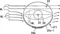
在图10A、图10B以及图10C中图示了配置在图3A及图3B中所图示的钟表模块24的外周面上的三种天线装置AT1、AT2以及AT3。10A, 10B, and 10C illustrate three types of antenna devices AT1, AT2, and AT3 arranged on the outer peripheral surface of the
图10A中所图示的天线装置AT1具备具有钟表模块24外周面的长度的一半长度的天线芯部件20a-1和卷绕安装在天线芯部件20a-1的长度方向的中央部分的天线线圈20b,天线线圈20b的两端连接在钟表模块24中构成有种种接收信号利用元件22(参照图3A及图3B)的公知的钟表电路。The antenna device AT1 shown in FIG. 10A includes an
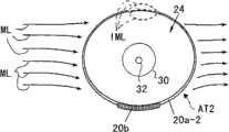
图10B中所图示的天线装置AT2具备具有比钟表模块24外周面的长度还稍微短的长度的天线芯部件20a-2和卷绕安装在天线芯部件20a-2的长度方向的中央部分的天线线圈20b。天线装置AT2的天线芯部件20a-2和图10A的天线装置AT1的天线芯部件20a-1仅仅在长度上不同。而且,天线装置AT2的天线线圈20b和图10A的天线装置AT1的天线线圈20b相同。The antenna device AT2 shown in FIG. 10B includes an
图10C中所图示的天线装置AT3具备在钟表模块24外周面的全周范围伸出的天线芯部件20a-3和卷绕安装在天线芯部件20a-3的长度方向的中央部分的天线线圈20b。天线装置AT3的天线芯部件20a-3和图10A的天线装置AT1的天线芯部件20a-1以及图10B的天线装置AT2的天线芯部件20a-2仅仅在长度上不同。而且,天线装置AT3的天线芯部件20a-3的天线线圈20b和图10A的天线装置AT1以及图10B的天线装置AT2各自的天线线圈20b相同。The antenna device AT3 shown in FIG. 10C includes an
如在图10A中所图示,在电波通过带有天线装置AT1的钟表模块24时,离开了天线芯部件20a-1的磁力线ML不流过天线芯部件20a-1而仅通过钟表模块24。通过天线芯部件20a-1的附近或与天线芯部件20a-1碰撞的磁力线ML被引导到天线芯部件20a-1并在天线线圈20b产生电动势。上述电动势产生流经天线芯部件20a-1的感应磁力线。该感应磁力线IML流经天线芯部件20a-1的两个伸出端部间。As shown in FIG. 10A , when radio waves pass through the
如在图10A中所图示,在天线芯部件20a-1的长度为钟表模块24的外周面的长度的一半的场合,由上述电动势产生的感应磁力线IML通过天线芯部件20a-1的两个伸出端部的伸出端间的钟表模块24中。其间,感应磁力线IML通过钟表模块24中的金属零部件产生涡流,结果在上述电动势上产生损失。这使图10A中所图示的天线装置AT1的接收灵敏度保持较低。As shown in FIG. 10A, when the length of the
如在图10B中所图示,在电波通过带有天线装置AT2的钟表模块24时,该电波的所有磁力线ML被引导到天线芯部件20a-2,通过天线线圈20b产生远比图10A的场合大的电动势。通过该大电动势产生的感应磁力线IML流经天线芯部件20a-2的两个伸出端部的伸出端间。As shown in FIG. 10B, when the radio wave passes through the
钟表模块24的存在于图10B中所图示天线装置AT2的天线芯部件20a-2的两个伸出端部的伸出端间的容积较小,所以通过钟表模块24的感应磁力线IML通过钟表模块24中的金属零部件几乎不产生涡流。然而,在天线芯部件20a-2的两个伸出端部的伸出端间流经钟表模块24的外侧的感应磁力线IML,流经收放了带有图10B中所图示的天线装置AT2的钟表模块24的未图示金属制钟表壳,并产生涡流。因此,尽管较小却在上述大电动势上产生损失。这意味着,图10B中所图示的天线装置AT2的接收灵敏度虽然远比图10A中所图示的天线装置AT1的接收灵敏度良好,但在接收灵敏度的提高上尚有与因上述涡流引起的损失相当的余地。The volume between the protruding ends of the two protruding ends of the
如在图10C中所图示,在电波通过带有天线装置AT3的钟表模块24时,该电波的所有磁力线ML也被引导到天线芯部件20a-3,通过天线线圈20b产生远比图10A的场合大且与图10B的场合同样的电动势。因该大电动势而产生的大感应磁力线IML的全部实质上只流经圆环状的天线芯部件20a-3中。As shown in Fig. 10C, when the electric wave passes through the
因此,只流经天线装置AT3的圆环状的天线芯部件20a-3中的感应磁力线IML,在钟表模块24中的金属零部件和收放了带有图10C中所图示的天线装置AT3的钟表模块24的未图示金属制钟表壳,实质上不产生涡流。这意味着,图10C中所图示的天线装置AT3的接收灵敏度比图10B中所图示的天线装置AT2的接收灵敏度还提高。Therefore, only the induced magnetic field lines IML in the annular
天线线圈20b因磁力线ML而产生的电动势在天线芯部件20a-3产生的感应磁力线IML的量与通过天线芯部件20a-3的卷绕有天线线圈20b的部分的磁力线ML的量成比例。The amount of induced magnetic force lines IML generated in the
因此,与其如图10C中所图示的天线装置AT3的圆环状的天线芯部件20a-3那样,天线芯部件20a-3的横截面积在天线芯部件20a-3的全周范围相同,不如将天线芯部件20a-3的横截面积设定成,从位于与卷绕有天线线圈20b的部分正相反的位置的天线芯部件20a-3的部分朝向卷绕有天线线圈20b的天线芯部件20a-3的部分渐渐变大,或者使形成位于与卷绕有天线线圈20b的部分正相反的位置的天线芯部件20a-3的部分的磁性体的磁阻变得比形成卷绕有天线线圈20b的天线芯部件20a-3的部分的磁性体的磁阻还大。Therefore, like the annular
由此,可提高图10C中所图示的天线装置AT3的接收灵敏度,而不必扩大将天线装置AT3组合到钟表模块24的外周面上时的组合整体的外径尺寸的大小。Thus, the receiving sensitivity of the antenna device AT3 shown in FIG. 10C can be improved without increasing the size of the outer diameter of the entire assembly when the antenna device AT3 is combined on the outer peripheral surface of the
[圆环状天线部件的制造方法][Manufacturing method of circular loop antenna part]
下面,一边参照图10A、图10B以及图10C一边说明图10C中所图示的圆环状天线芯部件20a-3的三个种类的制造方法。Next, three types of manufacturing methods of the annular
在图11A中所图示的方法中,预先将天线芯部件20a-3的长度设定成比配置天线芯部件20a-3的钟表模块24的外周面的长度还长。在将天线芯部件20a-3配置在钟表模块24的外周面的规定的位置时,使天线芯部件20a-3的两个伸出端部的伸出端如图11A中所示那样重叠。而且根据需要将天线芯部件20a-3的两个伸出端部的重叠的伸出端利用包括粘接剂和胶带等在内的公知的固定方法来固定彼此以及/或固定在上述外周面上。In the method illustrated in FIG. 11A , the length of the
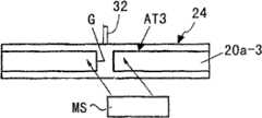
在图11B中所图示的方法中,预先将天线芯部件20a-3的长度设定成比配置天线芯部件20a-3的钟表模块24的外周面的长度还稍短。在将天线芯部件20a-3配置在钟表模块24的外周面的规定的位置时,对于在天线芯部件20a-3的两个伸出端部的伸出端间产生的间隙G以桥接上述伸出端的方式重叠磁性片MS,并将磁性片MS利用包括粘接剂和胶带等在内的公知的固定方法来固定在上述伸出端以及/或固定在上述外周面上。In the method shown in FIG. 11B , the length of the
在图11C中所图示的方法中,预先将天线芯部件20a-3的长度设定成比配置天线芯部件20a-3的钟表模块24的外周面的长度还稍短。在将天线芯部件20a-3配置在钟表模块24的外周面的规定的位置时,对于在天线芯部件20a-3的两个伸出端部的伸出端间产生的间隙G以桥接上述伸出端的方式重叠如包含微小磁性体在内的例如粘接剂那样的附着物。In the method shown in FIG. 11C , the length of the
[细长天线芯部件的制造方法][Manufacturing method of slender antenna core member]
在按照该发明的天线装置中使用的细长的天线芯部件,在上述的实施例及种种变型例中层叠了多枚细长片状的磁性体,或利用磁性体一体形成细长天线芯部件。然而,通过将尽管具有与细长天线芯部件的最终产品相同的长度但宽度比上述最终产品还宽的形状的磁性体片直至成为与上述最终产品的宽度相同的宽度为止沿宽度方向折叠,可得到上述最终产品。或者,通过多圈卷绕一条细长磁性体的线部件,可做成圆环状的细长天线芯部件的最终产品。再有,通过将规定长度的磁性体的多条细线材扎在一起,整体上还能够使具有规定的长度和规定的粗细的线部件为上述最终产品。In the elongated antenna core member used in the antenna device according to the present invention, a plurality of elongated sheet-shaped magnetic materials are laminated in the above-mentioned embodiments and various modifications, or the elongated antenna core member is integrally formed by using a magnetic material. . However, by folding a magnetic sheet having a shape wider than the above-mentioned final product despite having the same length as the final product of the slender antenna core member until it becomes the same width as the above-mentioned final product, it is possible to The above-mentioned final product is obtained. Alternatively, the final product of a ring-shaped elongated antenna core member can be obtained by winding a single elongated magnetic wire member multiple turns. Furthermore, by bundling a plurality of thin wires of a magnetic material having a predetermined length, the wire member having a predetermined length and a predetermined thickness as a whole can be made into the above-mentioned final product.
[电波利用设备的变型例][Modification of radio wave utilization equipment]
使用按照该发明的天线装置的电波利用设备在上述的实施例及种种变型例中为手表式电波钟表。然而,按照该发明的理念,上述电波利用设备可以是台式、壁挂式或者落地式电波钟表,可以是便携式收音机和便携式终端。The radio wave utilization equipment using the antenna device according to the present invention is a wristwatch type radio timepiece in the above-mentioned embodiment and various modifications. However, according to the idea of the invention, the above-mentioned radio wave utilization equipment may be a table-top, wall-mounted or floor-standing radio wave clock, and may be a portable radio or a portable terminal.
Claims (18)
Translated fromChineseApplications Claiming Priority (3)
| Application Number | Priority Date | Filing Date | Title |
|---|---|---|---|
| JP2008-147744 | 2008-06-05 | ||
| JP2008147744AJP2009296296A (en) | 2008-06-05 | 2008-06-05 | Antenna device, radio receiver, and antenna device manufacturing method |
| JP2008147744 | 2008-06-05 |
Publications (2)
| Publication Number | Publication Date |
|---|---|
| CN101599576A CN101599576A (en) | 2009-12-09 |
| CN101599576Btrue CN101599576B (en) | 2012-11-21 |
Family
ID=41400765
Family Applications (1)
| Application Number | Title | Priority Date | Filing Date |
|---|---|---|---|
| CN2009101426509AActiveCN101599576B (en) | 2008-06-05 | 2009-06-04 | Antenna device and radio wave-using apparatus |
Country Status (3)
| Country | Link |
|---|---|
| US (1) | US20090305657A1 (en) |
| JP (1) | JP2009296296A (en) |
| CN (1) | CN101599576B (en) |
Families Citing this family (14)
| Publication number | Priority date | Publication date | Assignee | Title |
|---|---|---|---|---|
| CN102279561A (en)* | 2011-04-11 | 2011-12-14 | 深圳市格雅表业有限公司 | Watch capable of automatically updating time through wireless network |
| US9483029B2 (en) | 2014-03-06 | 2016-11-01 | Seiko Epson Corporation | Timepiece and electronic timepiece |
| JP6200082B2 (en)* | 2014-06-02 | 2017-09-20 | 三菱電機株式会社 | Radio monitoring device |
| US10333200B2 (en) | 2015-02-17 | 2019-06-25 | Samsung Electronics Co., Ltd. | Portable device and near field communication chip |
| US10033092B2 (en)* | 2015-07-22 | 2018-07-24 | Futurewei Technologies, Inc. | Apparatus and method for utilizing a component with a helical antenna for communicating RF signals |
| US10615489B2 (en)* | 2016-06-08 | 2020-04-07 | Futurewei Technologies, Inc. | Wearable article apparatus and method with multiple antennas |
| US10431878B2 (en)* | 2016-06-23 | 2019-10-01 | Verizon Patent And Licensing Inc. | Wearable device design for 4G antennas |
| TWI629832B (en)* | 2016-06-30 | 2018-07-11 | 和碩聯合科技股份有限公司 | Wearable electronic device |
| KR102718339B1 (en)* | 2016-08-31 | 2024-10-18 | 삼성전자주식회사 | Antenna and electronic device with the same |
| WO2018044072A1 (en) | 2016-08-31 | 2018-03-08 | Samsung Electronics Co., Ltd. | Antenna and electronic device with the same |
| TWI628856B (en)* | 2017-01-10 | 2018-07-01 | 和碩聯合科技股份有限公司 | Wireless communication system and wearable electronic device comprising the same |
| CN106921033A (en)* | 2017-03-02 | 2017-07-04 | 上海德门电子科技有限公司 | Electronic equipment frame antenna structure |
| JP7357152B2 (en)* | 2019-10-10 | 2023-10-05 | グーグル エルエルシー | Water sealing design with antenna coexistence on electronic devices |
| USD1007337S1 (en)* | 2021-09-28 | 2023-12-12 | Chaohua Dai | Watchband |
Citations (3)
| Publication number | Priority date | Publication date | Assignee | Title |
|---|---|---|---|---|
| US6134188A (en)* | 1997-08-08 | 2000-10-17 | Junghans Uhren Gmbh | Antenna for a radio-controlled wristwatch |
| CN1755984A (en)* | 2004-09-30 | 2006-04-05 | 卡西欧计算机株式会社 | Antennas and Electronic Equipment |
| US7280438B2 (en)* | 2003-07-25 | 2007-10-09 | Seiko Epson Corporation | Electronic timepiece with an internal antenna |
Family Cites Families (3)
| Publication number | Priority date | Publication date | Assignee | Title |
|---|---|---|---|---|
| JP2004235701A (en)* | 2003-01-28 | 2004-08-19 | Casio Comput Co Ltd | Antenna and wristwatch with antenna |
| JP4523437B2 (en)* | 2005-02-01 | 2010-08-11 | セイコーインスツル株式会社 | Method for manufacturing antenna structure |
| JP2007240401A (en)* | 2006-03-10 | 2007-09-20 | Casio Comput Co Ltd | Radio clock and antenna device |
- 2008
- 2008-06-05JPJP2008147744Apatent/JP2009296296A/enactivePending
- 2009
- 2009-06-04USUS12/478,035patent/US20090305657A1/ennot_activeAbandoned
- 2009-06-04CNCN2009101426509Apatent/CN101599576B/enactiveActive
Patent Citations (3)
| Publication number | Priority date | Publication date | Assignee | Title |
|---|---|---|---|---|
| US6134188A (en)* | 1997-08-08 | 2000-10-17 | Junghans Uhren Gmbh | Antenna for a radio-controlled wristwatch |
| US7280438B2 (en)* | 2003-07-25 | 2007-10-09 | Seiko Epson Corporation | Electronic timepiece with an internal antenna |
| CN1755984A (en)* | 2004-09-30 | 2006-04-05 | 卡西欧计算机株式会社 | Antennas and Electronic Equipment |
Also Published As
| Publication number | Publication date |
|---|---|
| US20090305657A1 (en) | 2009-12-10 |
| JP2009296296A (en) | 2009-12-17 |
| CN101599576A (en) | 2009-12-09 |
Similar Documents
| Publication | Publication Date | Title |
|---|---|---|
| CN101599576B (en) | Antenna device and radio wave-using apparatus | |
| CN101789541B (en) | Antenna device and radio wave receiving device equipped with the antenna device | |
| US7280438B2 (en) | Electronic timepiece with an internal antenna | |
| CN101504535B (en) | Electronic timepiece with internal antenna | |
| US8259024B2 (en) | Radio wave receiver with an antenna structure | |
| JP2012163516A (en) | Antenna built-in electronic timepiece | |
| JP2010048605A (en) | Built-in antenna-type electronic timepiece | |
| JP2006153752A (en) | Electronic clock with built-in antenna | |
| JP2008141387A (en) | ANTENNA DEVICE, ANTENNA DEVICE MANUFACTURING METHOD, AND ELECTRONIC DEVICE | |
| JP4618120B2 (en) | Electronic clock with built-in antenna | |
| JP2005233900A (en) | Antenna for wrist watch, and antenna unit for wrist watch | |
| JP5228608B2 (en) | Electronic clock with built-in antenna | |
| JP2009270934A (en) | Electronic timepiece with built-in antenna and electronic device | |
| JP4273900B2 (en) | Electronic clock with built-in antenna | |
| CN103124000B (en) | The manufacture method of antenna, radio-wave receiver and antenna | |
| JP5262311B2 (en) | Electronics | |
| WO2007111217A1 (en) | Antenna and radio receiver having the antenna | |
| JP2005077361A (en) | Electronic clock with built-in antenna | |
| JP2006153648A (en) | Radio correction clock | |
| JP5211818B2 (en) | Electronic clock with built-in antenna | |
| JP2005049154A (en) | Electronic clock with built-in antenna | |
| JP5716470B2 (en) | Electronic clock with built-in antenna | |
| JP2019039740A (en) | Portable atomic watch | |
| JP2011166820A (en) | Electronic apparatus and method of manufacturing electronic apparatus | |
| JP2005062163A (en) | Electronic clock with built-in antenna |
Legal Events
| Date | Code | Title | Description |
|---|---|---|---|
| C06 | Publication | ||
| PB01 | Publication | ||
| C10 | Entry into substantive examination | ||
| SE01 | Entry into force of request for substantive examination | ||
| C14 | Grant of patent or utility model | ||
| GR01 | Patent grant |