CN101598702B - Systems and methods for measuring an analyte in a sample - Google Patents
Systems and methods for measuring an analyte in a sampleDownload PDFInfo
- Publication number
- CN101598702B CN101598702BCN2009101346025ACN200910134602ACN101598702BCN 101598702 BCN101598702 BCN 101598702BCN 2009101346025 ACN2009101346025 ACN 2009101346025ACN 200910134602 ACN200910134602 ACN 200910134602ACN 101598702 BCN101598702 BCN 101598702B
- Authority
- CN
- China
- Prior art keywords
- glucose concentration
- test
- sample
- electrode
- hematocrit level
- Prior art date
- Legal status (The legal status is an assumption and is not a legal conclusion. Google has not performed a legal analysis and makes no representation as to the accuracy of the status listed.)
- Expired - Fee Related
Links
Images


Classifications
- G—PHYSICS
- G01—MEASURING; TESTING
- G01N—INVESTIGATING OR ANALYSING MATERIALS BY DETERMINING THEIR CHEMICAL OR PHYSICAL PROPERTIES
- G01N27/00—Investigating or analysing materials by the use of electric, electrochemical, or magnetic means
- G01N27/26—Investigating or analysing materials by the use of electric, electrochemical, or magnetic means by investigating electrochemical variables; by using electrolysis or electrophoresis
- G01N27/416—Systems
- G01N27/4163—Systems checking the operation of, or calibrating, the measuring apparatus
- G—PHYSICS
- G01—MEASURING; TESTING
- G01N—INVESTIGATING OR ANALYSING MATERIALS BY DETERMINING THEIR CHEMICAL OR PHYSICAL PROPERTIES
- G01N27/00—Investigating or analysing materials by the use of electric, electrochemical, or magnetic means
- G01N27/26—Investigating or analysing materials by the use of electric, electrochemical, or magnetic means by investigating electrochemical variables; by using electrolysis or electrophoresis
- G01N27/28—Electrolytic cell components
- G01N27/30—Electrodes, e.g. test electrodes; Half-cells
- G01N27/327—Biochemical electrodes, e.g. electrical or mechanical details for in vitro measurements
- G01N27/3271—Amperometric enzyme electrodes for analytes in body fluids, e.g. glucose in blood
- G01N27/3274—Corrective measures, e.g. error detection, compensation for temperature or hematocrit, calibration
- G—PHYSICS
- G01—MEASURING; TESTING
- G01N—INVESTIGATING OR ANALYSING MATERIALS BY DETERMINING THEIR CHEMICAL OR PHYSICAL PROPERTIES
- G01N27/00—Investigating or analysing materials by the use of electric, electrochemical, or magnetic means
- G01N27/26—Investigating or analysing materials by the use of electric, electrochemical, or magnetic means by investigating electrochemical variables; by using electrolysis or electrophoresis
- C—CHEMISTRY; METALLURGY
- C12—BIOCHEMISTRY; BEER; SPIRITS; WINE; VINEGAR; MICROBIOLOGY; ENZYMOLOGY; MUTATION OR GENETIC ENGINEERING
- C12Q—MEASURING OR TESTING PROCESSES INVOLVING ENZYMES, NUCLEIC ACIDS OR MICROORGANISMS; COMPOSITIONS OR TEST PAPERS THEREFOR; PROCESSES OF PREPARING SUCH COMPOSITIONS; CONDITION-RESPONSIVE CONTROL IN MICROBIOLOGICAL OR ENZYMOLOGICAL PROCESSES
- C12Q1/00—Measuring or testing processes involving enzymes, nucleic acids or microorganisms; Compositions therefor; Processes of preparing such compositions
- C12Q1/001—Enzyme electrodes
- C12Q1/005—Enzyme electrodes involving specific analytes or enzymes
- C12Q1/006—Enzyme electrodes involving specific analytes or enzymes for glucose
- C—CHEMISTRY; METALLURGY
- C12—BIOCHEMISTRY; BEER; SPIRITS; WINE; VINEGAR; MICROBIOLOGY; ENZYMOLOGY; MUTATION OR GENETIC ENGINEERING
- C12Q—MEASURING OR TESTING PROCESSES INVOLVING ENZYMES, NUCLEIC ACIDS OR MICROORGANISMS; COMPOSITIONS OR TEST PAPERS THEREFOR; PROCESSES OF PREPARING SUCH COMPOSITIONS; CONDITION-RESPONSIVE CONTROL IN MICROBIOLOGICAL OR ENZYMOLOGICAL PROCESSES
- C12Q1/00—Measuring or testing processes involving enzymes, nucleic acids or microorganisms; Compositions therefor; Processes of preparing such compositions
- C12Q1/54—Measuring or testing processes involving enzymes, nucleic acids or microorganisms; Compositions therefor; Processes of preparing such compositions involving glucose or galactose
- G—PHYSICS
- G01—MEASURING; TESTING
- G01N—INVESTIGATING OR ANALYSING MATERIALS BY DETERMINING THEIR CHEMICAL OR PHYSICAL PROPERTIES
- G01N33/00—Investigating or analysing materials by specific methods not covered by groups G01N1/00 - G01N31/00
- G01N33/48—Biological material, e.g. blood, urine; Haemocytometers
- G01N33/483—Physical analysis of biological material
- G01N33/487—Physical analysis of biological material of liquid biological material
- G01N33/49—Blood
Landscapes
- Health & Medical Sciences (AREA)
- Life Sciences & Earth Sciences (AREA)
- Chemical & Material Sciences (AREA)
- Physics & Mathematics (AREA)
- Engineering & Computer Science (AREA)
- Biochemistry (AREA)
- Molecular Biology (AREA)
- Analytical Chemistry (AREA)
- General Health & Medical Sciences (AREA)
- Immunology (AREA)
- Organic Chemistry (AREA)
- Hematology (AREA)
- Pathology (AREA)
- General Physics & Mathematics (AREA)
- Electrochemistry (AREA)
- Proteomics, Peptides & Aminoacids (AREA)
- Wood Science & Technology (AREA)
- Zoology (AREA)
- Chemical Kinetics & Catalysis (AREA)
- Biophysics (AREA)
- Biomedical Technology (AREA)
- Emergency Medicine (AREA)
- Bioinformatics & Cheminformatics (AREA)
- General Engineering & Computer Science (AREA)
- Genetics & Genomics (AREA)
- Biotechnology (AREA)
- Microbiology (AREA)
- Ecology (AREA)
- Urology & Nephrology (AREA)
- Food Science & Technology (AREA)
- Medicinal Chemistry (AREA)
- Investigating Or Analysing Biological Materials (AREA)
- Investigating Or Analyzing Materials By The Use Of Electric Means (AREA)
- Measurement Of The Respiration, Hearing Ability, Form, And Blood Characteristics Of Living Organisms (AREA)
Abstract
Description
Translated fromChinese发明领域field of invention
本发明涉及检测样品中分析物浓度的方法和系统。The present invention relates to methods and systems for detecting the concentration of an analyte in a sample.
发明背景Background of the invention
在今天的社会中,对生理液体(如血液或血液衍生物)中分析物的检测越来越重要。分析物的检测分析具有多种应用,包括临床实验室测试,家庭测试等,这些测试结果在多种疾病情况的诊断和处理中起着显著的作用。关注的分析物包括糖尿病处理中的葡萄糖,胆固醇及其类似物。响应分析物检测不断提高的重要性,已经研发出了多种临床和家用的分析检测方法和仪器。In today's society, the detection of analytes in physiological fluids such as blood or blood derivatives is increasingly important. Analyte detection assays have diverse applications including clinical laboratory tests, home tests, etc., and the results of these tests play a prominent role in the diagnosis and management of various disease conditions. Analytes of interest include glucose, cholesterol and their analogs in diabetes management. In response to the increasing importance of analyte detection, a variety of clinical and home analytical assays and instruments have been developed.
一种用于分析物检测的方法为电化学方法。在这样的方法中,将含水液体样品置于电化学池中的样品接受室中,所述电化学池至少包括两个电极,例如,一个对电极和一个工作电极。所述分析物与氧化还原试剂反应形成可氧化物(或可还原物),其数量对应于分析物的浓度。然后电化学方法评估存在的可氧化物(或可还原物)的量,以及初始样品中存在的分析物的量。One method for analyte detection is electrochemical. In such methods, an aqueous liquid sample is placed in a sample receiving chamber in an electrochemical cell comprising at least two electrodes, eg, a counter electrode and a working electrode. The analyte reacts with a redox reagent to form an oxidizable (or reducible) species in an amount corresponding to the concentration of the analyte. The electrochemical method then evaluates the amount of oxidizable (or reducible) species present, as well as the amount of analyte present in the original sample.
这样的系统容易出现不同的无效和/或误差状况。例如,当待测生理样品是全血或其中的一种衍生物时,在最终分析物浓度测量中样品的血细胞比容可能成为分析误差一个来源。因此,在电化学测量法中,分析物浓度由所得的时间-电流瞬态得出,血细胞比容的增大能提高样品的粘性,反过来,却减慢酶,分析物和介质的扩散,因此削弱测试电流,从而引起分析误差。另外,样品接受室的部分填充或双-填充,有缺陷的测试片和/或样品的泄漏会导致错误的和/或无效的测试。Such systems are prone to various invalid and/or error conditions. For example, when the physiological sample to be measured is whole blood or a derivative thereof, the hematocrit of the sample can be a source of analytical error in the final analyte concentration measurement. Thus, in electrochemical measurements where the analyte concentration is derived from the resulting time-current transient, an increase in the hematocrit increases the viscosity of the sample which, in turn, slows down the diffusion of enzymes, analytes and mediators, The test current is thus weakened, causing analysis errors. Additionally, partial filling or double-filling of the sample receiving chamber, defective test strips and/or leaking of the sample can lead to erroneous and/or invalid tests.
发明概述Summary of the invention
提供了计算样品中校正的分析物浓度的方法的多个方面。也就是,所述方法典型地包括初始分析物的检测,根据各种系统测量和/或参数确定校正系数,和根据校正系数修正初始分析物浓度,从而克服一些误差来源。例如,分析物为葡萄糖,误差源是增高的血细胞比容水平,如果没有解决则会导致错误的读数。其他方法解决了多种系统误差如双进样,最大电流校对,最小电流校对,高电阻通道(high track resistance),和/或泄漏。尽管下面所述方法针对葡萄糖检测,但其他各种各样的方法都在本发明的实质范围内。例如,所述方法能够用于检测或测量乳酸,胆固醇,血红蛋白或所有抗氧化剂。Aspects of a method of calculating a corrected analyte concentration in a sample are provided. That is, the method typically includes detection of an initial analyte, determining a correction factor based on various system measurements and/or parameters, and correcting the initial analyte concentration based on the correction factor to overcome some source of error. For example, with the analyte being glucose, the source of error is elevated hematocrit levels, which if not addressed can lead to erroneous readings. Other methods account for various systematic errors such as double injection, maximum current calibration, minimum current calibration, high track resistance, and/or leakage. Although the methods described below are directed to glucose detection, a wide variety of other methods are within the spirit of the invention. For example, the method can be used to detect or measure lactate, cholesterol, hemoglobin or all antioxidants.
使用中,所述方法通过一电化学池实施,所述电化学池在尺寸和结构上能够容纳样品(如,血液)。典型地,所述电化学池包括至少结构距离如此接近的两电极,以至于所述电极能够用少量的液体弄湿。考虑到一些误差源,多种电化学方法能够测定准确的分析物浓度,或者在一个或多个施加的电压期间通过测定多种的电流读数来测定一些系统误差,利用多种读数测定校正系数,和利用校正系数测定校正的分析物浓度。电化学池结合测量仪使用。一个测量仪中的电源,如电池,在测量仪中被用来通过电极施加一电压或一系列的电压,从而引起电流产生。电流流动通过测量仪中的电路测量,其与时间呈函数关系,电流测量能够用于推出目标分析物的浓度。In use, the method is performed with an electrochemical cell sized and configured to accommodate a sample (eg, blood). Typically, the electrochemical cell includes at least two electrodes positioned in such close proximity that the electrodes can be wetted with a small amount of liquid. Taking into account several sources of error, multiple electrochemical methods can determine the exact analyte concentration, or some systematic error can be determined by taking multiple current readings during one or more applied voltages, using multiple readings to determine the correction factor, and determining the corrected analyte concentration using the correction factor. An electrochemical cell is used in conjunction with the meter. A power source in a meter, such as a battery, used in a meter to apply a voltage or series of voltages across electrodes to cause an electrical current to be generated. Current flow is measured by circuitry in the meter as a function of time, and the current measurement can be used to deduce the concentration of the analyte of interest.
典型地,在此提供的所述方法包括以特定的预设时间间隔施加多种测试电压,测量这些时间间隔期间的测试电流,利用这些测得的结果确定初始分析物浓度,校正系数,误差源和校正的分析物浓度。例如,所述方法包括将含有未知浓度葡萄糖的样品(如,血液)置于电化学池,在第一时间间隔T1中在第一电极和第二电极之间施加第一测试电压V1,其足以在第二电极上氧化被还原的介质。另外,所述方法包括在第二时间间隔T2中在第一电极和第二电极之间施加第二测试电压V2,其足以在第一电极上氧化被还原的介质,其中第一测试电压V1在第二测试电压V2之前施加。在这个实施方案中,所述方法包括在第一时间间隔T1和第二时间间隔T2期间,根据测试电流值计算初始葡萄糖浓度G1,计算误差源,在这种情况下增高的血细胞比容水平H并且根据初始葡萄糖浓度G1和血细胞比容水平H计算校正的葡萄糖浓度G2。Typically, the methods provided herein include applying various test voltages at specific preset time intervals, measuring test currents during these time intervals, and using these measured results to determine initial analyte concentrations, correction factors, error sources and corrected analyte concentrations. For example, the method comprises placing a sample (e.g. blood) containing an unknown concentration of glucose in an electrochemical cell, applying a first test voltageV1 between a first electrode and a second electrode during a first time intervalT1 , It is sufficient to oxidize the reduced mediator on the second electrode. Additionally, the method includes applying a second test voltage V2 between the first electrode and the second electrode during a second time interval T2 , sufficient to oxidize the reduced medium on the first electrode, wherein the first test voltageV1 is applied before the second test voltageV2 . In this embodiment, the method comprises, during the first time intervalT1 and the second time intervalT2 , calculating the initial glucose concentrationG1 from the test current value, calculating the source of error, in this case an increased hematocrit The hematocrit level H and the corrected glucose concentrationG2 are calculated from the initial glucose concentrationG1 and the hematocrit level H.
在一实施方案中,如果血细胞比容水平H低于较低的预设血细胞比容水平HL(如,约30%),初始葡萄糖浓度G1低于较高的预设葡萄糖浓度GU(如,约300mg//dL),校正的葡萄糖浓度的计算步骤包括利用第一函数计算校正值Corr。例如,第一函数为方程Corr=K1(HL-H)G1,其中Corr为校正值,K1为第一常数(如,约-0.004),HL为较低的预设血细胞比容水平(如,约30%),H为血细胞比容水平,G1为初始葡萄糖浓度。典型的,方程中的多种常数为经验推导得出的,其中一系列的测试结果由测量系统采用含有横跨目标范围的不同血细胞比容和葡萄糖浓度的全血得出。通常,然后使用非线性最小平方拟合,常数由电流值推导得出的目标参数值和实际检测的参数值之间具有最小的总差而确定。目标参数至少部分取决于所测常数。例如,如果参数构成评估样品血细胞比容的方程的一部分,那末样品的血细胞比容将成为目标参数。上面给出的方程中的参数Corr,目标参数是血液中的葡萄糖浓度。对本领域技术人员而言,能够意识到利用各种其他的统计分析方法得出常数值。In one embodiment, if the hematocrit level H is lower than a lower preset hematocrit levelHL (eg, about 30%), the initial glucose concentrationG is lower than a higher preset glucose concentration GU ( For example, about 300 mg//dL), the step of calculating the corrected glucose concentration includes calculating a correction value Corr using a first function. For example, the first function is the equation Corr=K1 (HL -H)G1 , where Corr is the correction value, K1 is the first constant (eg, about -0.004), andHL is the lower preset hematocrit level (eg, about 30%), H is the hematocrit level, andG1 is the initial glucose concentration. Typically, various constants in the equation are derived empirically, where a series of test results are derived by the measurement system using whole blood containing different hematocrit and glucose concentrations across the target range. Typically, then using a nonlinear least squares fit, the constant is determined with the smallest total difference between the target parameter value derived from the current value and the actual detected parameter value. The target parameter depends at least in part on the measured constant. For example, if a parameter forms part of an equation for evaluating the hematocrit of a sample, then the hematocrit of the sample will be the parameter of interest. Parameter Corr in the equation given above, the target parameter is the glucose concentration in the blood. Those skilled in the art will appreciate that various other statistical analysis methods are used to derive the constant value.
如果血细胞比容水平和初始葡萄糖浓度处于其他范围内,则可以检测校正系数。例如,计算第二葡萄糖浓度的步骤包括利用第二函数计算校正值Corr,如果血细胞比容H低于较低的预设血细胞比容水平HL(如,约30%)并且初始葡萄糖浓度G1大于较高的预设葡萄糖浓度GU(如,约300mg/dL)。在该实施方案中,所述方法也可包括根据初始葡萄糖浓度G1,血细胞比容水平H和校正值Corr计算校正的葡萄糖浓度G2。另外,第二函数可以为方程如Corr=K2(HL-H)(Gmax-G1),其中Corr为校正值,K2为第二常数(如,-0.004),HL为较低的预设血细胞比容水平(如,约30%),H为血细胞比容水平,Gmax为预设最大葡萄糖浓度(如,约600mg/dL),G1为第一葡萄糖浓度。If the hematocrit level and initial glucose concentration are within other ranges, the correction factor can be detected. For example, the step of calculating the second glucose concentration includes using the second function to calculate a correction value Corr if the hematocrit H is below a lower preset hematocrit levelHL (eg, about 30%) and the initial glucose concentrationG Greater than a higher preset glucose concentration GU (eg, about 300 mg/dL). In this embodiment, the method may also include calculating a corrected glucose concentrationG2 based on the initial glucose concentrationG1 , the hematocrit level H and the correction value Corr. In addition, the second function can be an equation such as Corr=K2 (HL -H)(Gmax -G1 ), where Corr is a correction value, K2 is a second constant (eg, -0.004), and HL is a comparative value. A low preset hematocrit level (eg, about 30%), H is the hematocrit level, Gmax is the preset maximum glucose concentration (eg, about 600 mg/dL), and G1 is the first glucose concentration.
在某些条件下,所述方法可以设定和使用等于0的校正值Corr。例如,在实施方案中,当血细胞比容水平H大于较高的预设血细胞比容水平HU(如,约50%)并且初始葡萄糖浓度G1小于较低的预设葡萄糖浓度GL(如,约100mg/dL)或者血细胞比容水平H小于较高的预设血细胞比容水平HU(如,约50%)并且大于较低的预设血细胞比容水平HL(如,约30%)时,校正的葡萄糖浓度G2基本上等于初始葡萄糖浓度G1(如,Corr=0)。Under certain conditions, the method may set and use a correction value Corr equal to zero. For example, in an embodiment, when the hematocrit level H is greater than a higher preset hematocrit levelHU (eg, about 50%) and the initial glucose concentrationG is less than a lower preset glucose concentrationGL (eg, , about 100 mg/dL) or the hematocrit level H is less than the upper preset hematocrit levelHU (eg, about 50%) and greater than the lower preset hematocrit levelHL (eg, about 30%) ), the corrected glucose concentration G2 is substantially equal to the initial glucose concentration G1 (eg, Corr=0).
在一个实施方案中,当血细胞比容水平H大于较高的预设血细胞比容水平HU(如,大约50%)并且初始葡萄糖浓度G1大于较低的预设葡萄糖浓度GL(如,大约100mg/dL)时,计算第二葡萄糖浓度G2的步骤包括利用第四函数计算校正值Corr。该项实施方案中,该方法还包括基于初始葡萄糖浓度G1、血细胞比容水平H、和校正值Corr计算校正的葡萄糖浓度G2。另外,第四函数可以表述为方程如Corr=K4(H-HU)(G1-GL),Corr为校正值,K4为第四常数(如,0.011),H为血细胞比容水平,HU为较高的预设血细胞比容水平(如,约50%),G1为初始葡萄糖浓度,和GL为较低的预设葡萄糖浓度(如,约100mg/dL)。In one embodiment, when the hematocrit level H is greater than a higher preset hematocrit levelHU (e.g., about 50%) and the initial glucose concentration G is greater thana lower preset glucose concentrationGL (e.g., When about 100 mg/dL), the step of calculating the second glucose concentrationG2 includes calculating the correction value Corr using the fourth function. In this embodiment, the method further includes calculating a corrected glucose concentrationG2 based on the initial glucose concentrationG1 , the hematocrit level H, and the correction value Corr. In addition, the fourth function can be expressed as an equation such as Corr=K4 (HHU )(G1-GL ), where Corr is the correction value, K4 is the fourth constant (eg, 0.011), H is the hematocrit level,HU is a higher preset hematocrit level (eg, about 50%), G1 is an initial glucose concentration, andGL is a lower preset glucose concentration (eg, about 100 mg/dL).
多种校正方程能用于得出校正的葡萄糖浓度值G2。例如,在某些实施方案中,根据相对于某葡萄糖阈值的初始葡萄糖浓度选择校正方程。也就是,所述方法包括利用一校正方程计算校正的葡萄糖浓度G2的步骤,在此情况下,初始葡萄糖浓度G1低于葡萄糖阈值,校正方程为G2=G1+Corr。另外,所述方法包括利用校正方程计算校正的葡萄糖浓度G2的步骤,如果初始葡萄糖浓度G1高于葡萄糖阈值,其校正方程为
对本领域技术人员而言,能够想到以任何数量或模式的时间间隔向样品施加任何数量和大小的测试电压。例如,在一实施方案中,在第一测试电压V1后立即施加第二测试电压V2。此外,第一测试电压V1具有第一极性,第二测试电压V2具有第二极性,其中第一极性在大小或信号上与第二极性相反。需要指出的是,第一和第二测试电压实质上能够提供任何需要的效果。例如,在一实施方案中,对于第二电极,第一测试电压V1在约-100mV到约-600mV间,和第二测试电压V2在约+100mV到+600mV间。另外,所述方法进一步包括在第三时间间隔T3中,在第一和第二电极之间施加第三测试电压V3,其中作为结果的测试电流绝对值实质上低于第二测试电压V2的测试电流绝对值。第三测试电压可在第一测试电压V1之前施加,或在需要的任何其他时间间隔(如,第二测试电压后)施加。另外,这里包括多种电极布置和/或结构。例如,在一实施方案中,第一电极和第二电极具有相对的布置。另外,可在第一电极上覆盖试剂层。It is conceivable to one skilled in the art that any number and magnitude of test voltages be applied to the sample at any number or pattern of time intervals. For example, in one embodiment, the second test voltage V2 is applied immediately after the first test voltage V1 . Furthermore, the first test voltage V1 has a first polarity and the second test voltage V2 has a second polarity, wherein the first polarity is opposite in magnitude or signal to the second polarity. It should be noted that the first and second test voltages can provide virtually any desired effect. For example, in one embodiment, for the second electrode, the first test voltage V1 is between about -100 mV and about -600 mV, and the second test voltage V2 is between about +100 mV and +600 mV. Additionally, the method further comprises applying a third test voltageV3 between the first and second electrodes during a third time intervalT3 , wherein the resulting absolute value of the test current is substantially lower than the second test voltage V2 absolute value of the test current. The third test voltage may be applied before the first test voltage V1 , or after any other time interval desired (eg, after the second test voltage). Additionally, various electrode arrangements and/or structures are contemplated herein. For example, in one embodiment, the first electrode and the second electrode have opposing arrangements. In addition, a reagent layer may be covered on the first electrode.
所述方法还提供了多种测试病人血细胞比容水平的手段。例如,血细胞比容水平H可以基于第一时间间隔T1和第二时间间隔T2期间的测试电流值。在一实施方案中,使用血细胞比容方程计算血细胞比容水平H。如,血细胞比容方程为H=K5ln(|i2|)+K6ln(G1)+K7其中H为血细胞比容水平,K5为第五常数(如,-76.001),i2为第二时间间隔期间的至少一电流值,K6为第六常数(如,56.024),G1为初始葡萄糖浓度,和K7为第七常数(如,250)。The method also provides a variety of means for testing the patient's hematocrit level. For example, the hematocrit level H may be based on the test current values during the first time intervalT1 and the second time intervalT2 . In one embodiment, the hematocrit level H is calculated using the hematocrit equation. For example, the hematocrit equation is H=K5 ln(|i2 |)+K6 ln(G1 )+K7 where H is the hematocrit level and K5 is the fifth constant (eg, -76.001) , i2 is at least one current value during the second time interval, K6 is a sixth constant (eg, 56.024), G1 is an initial glucose concentration, and K7 is a seventh constant (eg, 250).
另一方面,提供了一种计算分析物浓度的方法,其包括在第一时间间隔T1内,在第一和第二电极间施加第一测试电压V1足以在第二电极上氧化被还原的介质,在第二时间间隔T2内,在第一和第二电极间施加第二测试电压V2足以在第一电极上氧化被还原的介质。所述方法还包括根据第一时间间隔T1和第二时间间隔T2期间的测试电流值计算初始葡萄糖浓度G1。所述方法进一步包括计算血细胞比容水平H和如果初始葡萄糖浓度G1低于较高预设葡萄糖浓度GU并且血细胞比容水平低于较低预设血细胞比容水平HL则运用第一函数计算校正的葡萄糖浓度。所述方法还包括如果初始葡萄糖浓度G1高于较高预设葡萄糖浓度GU并且血细胞比容水平低于较低预设血细胞比容水平HL则运用第二函数计算校正的葡萄糖浓度,和如果初始葡萄糖浓度G1低于较低预设葡萄糖浓度GU并且血细胞比容水平高于较高预设血细胞比容水平HU则运用第三函数计算校正的葡萄糖浓度,和如果初始葡萄糖浓度G1高于较低预设葡萄糖浓度GL并且血细胞比容水平高于较高预设血细胞比容水平HU则运用第四函数计算校正的葡萄糖浓度。In another aspect, there is provided a method of calculating the concentration of an analyte comprising, during a first time intervalT1 , applying a first test voltageV1 between the first and second electrodes sufficient to oxidize and reduce at the second electrode During the second time intervalT2 , applying a second test voltageV2 between the first and second electrodes is sufficient to oxidize the reduced medium on the first electrode. The method also includes calculating an initial glucose concentration G1 based on the test current values during the first time interval T1 and the second time interval T2 . The method further comprises calculating the hematocrit level H and applying the first function if the initial glucose concentrationG is lower than the upper preset glucose concentration GU and the hematocrit level is lower than the lower preset hematocrit levelHL Calculate the corrected glucose concentration. The method further comprises calculating a corrected glucose concentration using a second function if the initial glucose concentrationG is higher than the upper preset glucose concentration GU and the hematocrit level is lower than the lower preset hematocrit level HL , and The third function is used to calculate the corrected glucose concentration if the initial glucose concentrationG is lower than the lower preset glucose concentration GU and the hematocrit level is higher than the upper preset hematocrit level HU , and if the initial glucose concentration G1 above the lower preset glucose concentrationGL and the hematocrit level is higher than the upper preset hematocrit levelHU then the corrected glucose concentration is calculated using the fourth function.
多种函数包括多种方程。例如,第一函数包括方程如Corr=K1(HL-H)G1,其中Corr为校正值,K1为第一常数(如,约-0.004),HL为较低的预设血细胞比容水平(如,约30%),H为血细胞比容水平,G1为初始葡萄糖浓度。第二函数包括方程如Corr=K2(HL-H)(Gmax-G1),其中Corr为校正值,K2为第二常数(如,-0.004),HL为较低预设血细胞比容水平(如,约30%),H为血细胞比容水平,Gmax为预设最大葡萄糖浓度(如,约600mg/dL),G1为初始葡萄糖浓度。第三函数包括方程如Corr=0,其中Corr为校正值,和第四函数包括方程如Corr=K4(H-HU)(G1-GL),Corr为校正值,K4为第四常数(如,0.011),H为血细胞比容水平,HU为较高预设血细胞比容水平(如,约50%),G1为初始葡萄糖浓度,和GL为较低预设葡萄糖浓度(如,约100mg/dL)。The various functions include various equations. For example, the first function includes an equation such as Corr=K1 (HL -H)G1 , where Corr is the correction value, K1 is a first constant (eg, about -0.004), andHL is the lower preset blood cell The hematocrit level (eg, about 30%), H is the hematocrit level, andG1 is the initial glucose concentration. The second function includes an equation such as Corr=K2 (HL -H)(Gmax -G1 ), where Corr is the correction value, K2 is the second constant (eg, -0.004), andHL is the lower preset The hematocrit level (eg, about 30%), H is the hematocrit level, Gmax is the preset maximum glucose concentration (eg, about 600 mg/dL), and G1 is the initial glucose concentration. The third function includes an equation such as Corr=0, where Corr is a correction value, and the fourth function includes an equation such as Corr=K4 (HHU )(G1-GL ), where Corr is a correction value and K4 is a fourth constant (e.g., 0.011), H is the hematocrit level,HU is the higher preset hematocrit level (e.g., about 50%),G is the initial glucose concentration, andGL is the lower preset glucose concentration ( eg, about 100 mg/dL).
另外,多种校正值能用于多种校正方程的实施方案从而提供校正的分析物值。例如,所述方法包括利用一校正方程计算校正葡萄糖浓度G2的步骤,如果初始葡萄糖浓度G1低于葡萄糖阈值,校正方程为G2=G1+Corr。另外,所述方法包括利用校正方程计算校正葡萄糖浓度G2的步骤,如果初始葡萄糖浓度G1高于葡萄糖阈值,其校正方程为
在一个实施方案中,所述方法包括在第三时间间隔T3中,在第一和第二电极之间施加第三测试电压V3,其中作为结果的测试电流绝对值实质上低于第二测试电压V2的测试电流绝对值。在该实施方案中,第三测试电压V3可在第一测试电压V1之前施加。在该实施方案中,第三测试电压V3为最大值,其导致测试电流足够低于施加第二电压V2的测试电流绝对值,从而减小V1和V2施加期间测量电流的干扰。V3施加期间较小的电流意味着电极上少量的氧化还原物发生电化学反应,从而使得施加V3时引起的电化学池中氧化还原物的浓度波动减小。In one embodiment, the method comprises applying a third test voltage V3 between the first and second electrodes during a third time interval T3 , wherein the resulting absolute value of the test current is substantially lower than the second The absolute value of the test current for the test voltageV2 . In this embodiment, the third test voltageV3 may be applied before the first test voltageV1 . In this embodiment, the third test voltageV3 is at a maximum value which results in a test current sufficiently lower than the absolute value of the test current at which the second voltageV2 is applied, thereby reducing disturbance of the measured current during the application ofV1 andV2 . The smaller current duringV3 application means that a small amount of redox species on the electrode reacts electrochemically, so that the concentration fluctuation of redox species in the electrochemical cell caused byV3 application is reduced.
提供了鉴别测试条缺陷(如高通道电阻)方法的多种实施方案。一方面,提供了一种方法,其中包括在第一时间间隔内,在第一和第二电极间施加第一测试电压足以在第二电极上氧化被还原的介质,在第二时间间隔内,在第一和第二电极间施加第二测试电压足以在第一电极上氧化被还原的介质。另外,只有第一测试电压在第一时间间隔施加实现该方法。所述方法也包括测量第一或第二测试时间间隔期间产生的第一测试电流和第二测试电流,其中在相同的测试时间间隔期间第二测试电流产生在第一测试电流之后,和根据第一测试电流和第二测试电流利用方程确定测试条是否有缺陷。在另一实施方案中,在第一测试电压之后立即施加第二测试电压。Various embodiments of methods of identifying test strip defects such as high channel resistance are provided. In one aspect, a method is provided, comprising applying a first test voltage between first and second electrodes sufficient to oxidize a reduced medium at the second electrode during a first time interval, and during a second time interval, Applying a second test voltage across the first and second electrodes is sufficient to oxidize the reduced mediator at the first electrode. Additionally, only the first test voltage is applied for the first time interval to implement the method. The method also includes measuring a first test current and a second test current generated during a first or second test time interval, wherein the second test current occurs after the first test current during the same test time interval, and according to the first test current A test current and a second test current use equations to determine whether the test strip is defective. In another embodiment, the second test voltage is applied immediately after the first test voltage.
在此,提供了该方程的多种实施方案。例如,方程包括第一测试电流和第二测试电流的比值。另外,方程包括第一测试电流和第一测试电流与第二测试电流差值的比值。其中一实施方案中,第一电流产生在第一或第二测试时间间隔的开始,并且第一测试电流为第一或第二测试时间间隔期间产生的最大电流。同时,第二电流产生在第一或第二测试时间间隔的结束,并且第二测试电流为第一或第二测试时间间隔期间产生的最小电流。在一例子中,
类似于上面,多种电极布置和/或结构包含在本发明的范围之内。例如,第一测试电压的极性与第二测试电压的极性相反。同时,第一电极和第二电极具有相面对的布置。另外,第一电压和/或第二电压可以是任何电压范围。例如,对应于第二电极的第一测试电压范围从约0至约-600mV,和对应于第二电极的第二测试电压范围从约10mV至约600mV。Similar to the above, various electrode arrangements and/or structures are within the scope of the present invention. For example, the polarity of the first test voltage is opposite to that of the second test voltage. Meanwhile, the first electrode and the second electrode have a facing arrangement. Additionally, the first voltage and/or the second voltage may be any voltage range. For example, the first test voltage corresponding to the second electrode ranges from about 0 to about −600 mV, and the second test voltage corresponding to the second electrode ranges from about 10 mV to about 600 mV.
如所指出的,利用所述方法的一个实施方案鉴别出的缺陷为高通道电阻。例如高通道电阻在电化学池中的电极连接点和电极之间。通道的作用在于提供电化学池中仪表电连接点和电极之间的电导通通道。当电流流向这些通道时,仪表施加的某些电压会根据欧姆定律沿这些通道消耗,电阻越高,电流流过通道电压下降越大。在此实施方案中,所述方法基于在电极之间施加电压后短时间内电流大于长时间后的电流,原因在于在短时间内初始高浓度的还原介质接近电极。如果通道电阻太高,当大的初始电流流动时,电流通过,沿通道产生的电压降将比理想的大。这种大于理想值的电压降导致在电化学池中电极两端的电压不足,反过来引起比可接受的通道电阻情况下的低电流通过。根据该实施方案,利用所述上述方法通过比较长时间中的电流得出短时间中低于理想值的电流,其中所述长时间中较低的电流本质上不受高通道电阻影响。As noted, the defect identified using one embodiment of the method was high channel resistance. An example of high channel resistance is between the electrode junction and the electrodes in an electrochemical cell. The function of the channel is to provide an electrical conduction channel between the meter's electrical connection point and the electrodes in the electrochemical cell. When current flows through these channels, some of the voltage applied by the meter is dissipated along these channels according to Ohm's law, the higher the resistance, the greater the voltage drop when the current flows through the channel. In this embodiment, the method is based on the fact that the current is greater for a short time after the application of a voltage between the electrodes than for a long time, due to the initial high concentration of reducing mediator approaching the electrodes for a short time. If the channel resistance is too high, when the large initial current flows, the current passing through it will create a larger than ideal voltage drop along the channel. This greater than ideal voltage drop results in insufficient voltage across the electrodes in the electrochemical cell, which in turn causes lower than acceptable channel resistance to pass current. According to this embodiment, a lower-than-ideal current in the short time period is obtained by comparing the currents in the long time period with the above method, wherein the lower current in the long time period is substantially unaffected by the high channel resistance.
另一方面,提供一种鉴别测试条缺陷(如,泄漏)的方法。所述方法包括在第一时间间隔内,在第一和第二电极间施加第一测试电压,其足以在第二电极上氧化被还原的介质,在第二时间间隔内,在第一和第二电极间施加第二测试电压,其足以在第一电极上氧化被还原的介质。所述方法还包括测量第二测试时间间隔中的第一测试电流,第二测试电流,第三测试电流,第四测试电流,计算基于第一测试电流和第二测试电流第一比值的第一对数,计算基于第三测试电流和第四测试电流第二比值的第二对数,和利用基于第一对数和第二对数的方程确定测试条是否有缺陷。典型的实施方案中,所述缺陷为隔片和第一电极之间液体的泄漏。在一些实施方案中,试剂层布置在第一电极上,以致于试剂层的部分在隔片和第一电极之间。In another aspect, a method of identifying a test strip defect (eg, leak) is provided. The method includes applying, during a first time interval, a first test voltage between the first and second electrodes sufficient to oxidize the reduced medium at the second electrode, and during a second time interval between the first and second electrodes. A second test voltage is applied between the two electrodes sufficient to oxidize the reduced medium on the first electrode. The method also includes measuring a first test current, a second test current, a third test current, and a fourth test current in a second test time interval, and calculating a first test current based on a first ratio of the first test current to the second test current. Logarithmically, calculating a second logarithm based on a second ratio of the third test current to the fourth test current, and determining whether the test strip is defective using an equation based on the first logarithm and the second logarithm. In a typical embodiment, the defect is a leak of liquid between the separator and the first electrode. In some embodiments, the reagent layer is disposed on the first electrode such that a portion of the reagent layer is between the spacer and the first electrode.
类似于上述,提供了多种方程。在典型的实施方案中,由方程
在一实施方案中,第一测试电流和第二测试电流为第二时间间隔期间的两最大电流值。在一实施方案中,第四测试电流为第二时间间隔期间产生的最小电流值。同时,在一实施方案中,第四测试电流和第三测试电流之间的差值大于第二测试电流和第一测试电流之间的差值。在该实施方案中,所述方法包括比较由i1,i2,i3,和i4所测电流表达的电流对时间的分布图形状和预设阈值表达的理想形状,从而判断或确定电流瞬间变化形状是否能接受。In one embodiment, the first test current and the second test current are the two maximum current values during the second time interval. In one embodiment, the fourth test current is the minimum current value generated during the second time interval. Meanwhile, in one embodiment, the difference between the fourth test current and the third test current is greater than the difference between the second test current and the first test current. In this embodiment, the method includes comparing the shape of the current vs. time profile expressed by the currents measured by i1 , i2 , i3 , and i4 with the ideal shape expressed by a preset threshold value, thereby judging or determining the current Is it acceptable to change shape instantaneously?
另外,在此提供了鉴别利用测试条测试时鉴别误差的方法的多个方面。其中一方面,所述方法包括在测试时间间隔中在第一电极和第二电极间施加测试电压,连续测量第一测试电流,第二测试电流和第三测试电流,和通过基于第二测试电流和第一测试电流绝对值与第三测试电流绝对值之和的方程确定是否产生误差。利用所各测试间的时间差。例如,第一测试电流和第二测试电流测量之间的时间差范围从约1纳秒到约100毫秒。同时,第一测试电流和第三测试电流测量之间的时间差范围从约1纳秒到约100毫秒。Additionally, various aspects of methods of identifying errors when testing with a test strip are provided herein. In one aspect, the method includes applying a test voltage between the first electrode and the second electrode during the test time interval, continuously measuring the first test current, the second test current and the third test current, and by An equation that sums the absolute value of the first test current and the absolute value of the third test current determines whether an error occurs. Take advantage of the time difference between all tests. For example, the time difference between the first test current and the second test current measurements ranges from about 1 nanosecond to about 100 milliseconds. Also, the time difference between the first test current and the third test current measurements ranges from about 1 nanosecond to about 100 milliseconds.
类似于上面,在此提供了多种方程,例如,在一典型的实施方案中,方程为Y=2*abs(i(t))-abs(i(t-x))-abs(i(t+x)),其中i(t)为第二测试电流,i(t-x)为第一测试电流,i(t+x)为第三测试电流,t为时间并且x为时间的增量,和abs代表绝对函数。在一实施方案中,方程为Z=abs(i(t+x))-abs(i(t)),其中,i(t)为第二测试电流,i(t+x)为第三测试电流,t为时间和x为时间的增量,和abs代表绝对函数。这些方程能用于判断电流非理想的快速增加或下降,这些变化指示测试时误差的产生。Similar to above, various equations are provided here, for example, in a typical embodiment, the equation is Y=2*abs(i(t))-abs(i(t-x))-abs(i(t+ x)), where i(t) is the second test current, i(t-x) is the first test current, i(t+x) is the third test current, t is time and x is the increment of time, and abs stands for an absolute function. In one embodiment, the equation is Z=abs(i(t+x))-abs(i(t)), where i(t) is the second test current and i(t+x) is the third test current current, t is time and x is the increment of time, and abs represents the absolute function. These equations can be used to determine the non-ideal rapid increase or decrease in current, these changes indicate the generation of errors in the test.
在此提供了系统用于检测分析物浓度或确定操作或系统误差的多种情况。例如,在一实施方案中,装置包括具有至少两个电极和在尺寸结构上容纳样品(如,血液)的电化学池。电化学池进一步配置检测初始分析物浓度(如,葡萄糖)和配置在预设时间在第一和第二电极产生预设电压,和进一步配置在预设时间内测量至少一样品产生的电流。所述系统还包括一处理器,用于接收来自电化学池的一系列的数据,其中数据包括初始分析物浓度,至少一个(或多个)施加的电压值,和至少一产生的电流。所述处理器进一步配置利用所述数据确定校正的分析物浓度或确定系统误差(如,高通道电阻,泄漏等)。在一实施方案中,所述处理器用于根据极限血细胞比容水平提供校正的葡萄糖浓度。在执行这一功能中,所述处理器利用一系列的方程根据血细胞比容水平和初始葡萄糖浓度确定校正条件。所述处理器能以多方式配置从而利用其他取决于理想校正和/或电化学池中得到的数据的方程或参数。A number of instances where the system is used to detect analyte concentrations or to determine operational or system errors are provided herein. For example, in one embodiment, a device includes an electrochemical cell having at least two electrodes and sized to hold a sample (eg, blood). The electrochemical cell is further configured to detect an initial analyte concentration (eg, glucose) and configured to generate a predetermined voltage at the first and second electrodes for a predetermined time, and is further configured to measure a current generated by at least one sample for a predetermined time. The system also includes a processor for receiving a series of data from the electrochemical cell, wherein the data includes an initial analyte concentration, at least one (or more) applied voltage values, and at least one generated current. The processor is further configured to use the data to determine corrected analyte concentrations or to determine systematic errors (eg, high channel resistance, leakage, etc.). In one embodiment, the processor is configured to provide a corrected glucose concentration based on a limiting hematocrit level. In performing this function, the processor utilizes a series of equations to determine calibration conditions based on the hematocrit level and the initial glucose concentration. The processor can be configured in various ways to utilize other equations or parameters that depend on the desired calibration and/or data obtained in the electrochemical cell.
在此提供了一种用于确定校正分析物浓度的装置的多种情况。其中一种情况,所述装置包括测试条,所述测试条包括一用于接收样品的样品反应室,以致于所述样品与至少第一和第二电极接触。所述装置还包括布置在至少一电极上的试剂层,其中所述试剂层至少由一种成分(如,介质,酶等)形成,所述成分与样品反应,在样品中至少两个时间间隔内将至少两个电压施加于样品,产生相应的电流,指示初始分析物浓度和校正的分析物浓度。Embodiments of an apparatus for determining a corrected analyte concentration are provided herein. In one aspect, the device includes a test strip including a sample reaction chamber for receiving a sample such that the sample is in contact with at least first and second electrodes. The device also includes a reagent layer disposed on at least one electrode, wherein the reagent layer is formed from at least one component (e.g., mediator, enzyme, etc.) that reacts with the sample for at least two time intervals in the sample At least two voltages are applied to the sample to generate corresponding currents indicative of an initial analyte concentration and a corrected analyte concentration.
附图详述Detailed description of the drawings
通过下面的详述结合附图能更深入地理解本发明,其中:The present invention can be understood more deeply by following detailed description in conjunction with accompanying drawing, wherein:
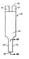
图1A为测试条透视图;Figure 1A is a perspective view of a test strip;
图1B为图1A所示测试条的分解图;Figure 1B is an exploded view of the test strip shown in Figure 1A;
图1C为图1A所示测试条末梢部的透视图;Figure 1C is a perspective view of the distal end of the test strip shown in Figure 1A;
图2为图1A所示测试条的底平面图;Figure 2 is a bottom plan view of the test strip shown in Figure 1A;
图3为图1A所示测试条的侧平面图;Figure 3 is a side plan view of the test strip shown in Figure 1A;
图4A为图1A所示测试条的顶平面图;Figure 4A is a top plan view of the test strip shown in Figure 1A;
图4B为图4A中与箭头4B-4B一致的测试条末梢部分的部分侧视图;Figure 4B is a partial side view of the distal portion of the test strip corresponding to
图5为测试仪与测试条接触块电接触的简单示意图;Fig. 5 is a simple schematic diagram of the electrical contact between the tester and the test strip contact block;
图6为指定时间段测试仪施加一系列测试电压的测试电压波形;Fig. 6 applies the test voltage waveform of a series of test voltages for the designated time period tester;
图7所示为图6所示测试电压波形产生的测试电流瞬态;Figure 7 shows the test current transient produced by the test voltage waveform shown in Figure 6;
图8为描述利用极限血细胞比容水平计算样品中分析物浓度典型实施方案的流程图;Figure 8 is a flowchart depicting an exemplary embodiment for calculating the concentration of an analyte in a sample using a limiting hematocrit level;
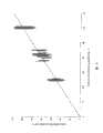
图9为利用参考法测得的血细胞比容水平和利用图1的测试条测得的血细胞比容水平之间校正的表格;Figure 9 is a table of calibration between hematocrit levels measured using the reference method and hematocrit levels measured using the test strip of Figure 1;
图10所示为利用含有宽范围血细胞比容水平的样品测试的大量测试条的偏视图;Figure 10 is a partial view of a number of test strips tested with samples containing a wide range of hematocrit levels;
图11为鉴别系统误差的方法实施方案的流程图;Figure 11 is a flow chart of an embodiment of a method for identifying systematic errors;
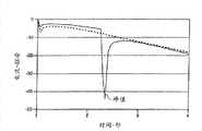
图12为使用者进行双剂量(实线)和不进行双剂量(虚线)时,第二测试时间段的测试电流瞬态;Fig. 12 is when the user performs double dose (solid line) and does not perform double dose (dotted line), the test current transient state of the second test period;
图13为测试仪产生后开始误差(实线)和不产生(虚线)时,第二测试时间段的测试电流瞬态;Figure 13 is the test current transient state of the second test period when the tester produces the starting error (solid line) and does not produce (dotted line);
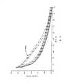
图14具有高电阻通道(方形)和低电阻通道(三角形)的测试条,第三测试时间段的测试电流瞬态;Figure 14 has a test strip with high resistance channel (square) and low resistance channel (triangle), the test current transient of the third test period;
图15为指示高电阻测测试条组能与低电阻测试条组区分的大量比值的表;Figure 15 is a table indicating a number of ratios by which a high resistance test strip set can be distinguished from a low resistance test strip set;
图16为隔片和第一电极间具有泄漏的测试条组(方形)和足够低泄漏的测试条(圆形和三角形)的测试电流瞬态;和Figure 16 is a test current transient for a test strip set (square) and a sufficiently low leakage test strip (circle and triangle) with leakage between the spacer and the first electrode; and
图17为用于鉴别不同制备条件下所得测试条组的液体泄漏的比值表。Figure 17 is a table of ratios used to identify liquid leakage from test strip sets obtained under different preparation conditions.
发明详述Detailed description of the invention
在此通过描述典型的实施方案来全面的理解所述结构,功能,制造,装置的使用,系统和方法。一个或更多的实施方案结合附图来阐明。对于本领域技术人员而言,在此特定描述的以及附图阐述的仪器和方法并不限于典型的实施方案,本发明公开的范围完全由权利要求定义。一典型实施方案解释或描述的特征也可以结合其他实施方案的特征。这些改进或变型都在本发明公开的范围之内。Typical embodiments are described herein to provide a full understanding of the structure, function, manufacture, use of devices, systems and methods. One or more embodiments are illustrated in conjunction with the accompanying drawings. To those skilled in the art, the apparatus and methods specifically described herein and illustrated in the accompanying drawings are not limited to the exemplary embodiments, and the scope of the present disclosure is defined solely by the claims. Features illustrated or described in one exemplary embodiment may also be combined with features of other embodiments. These improvements or modifications are all within the scope of the present invention.
本发明公开的系统和方法适用于检测多种样品中的多种分析物,尤其适用于全血,血浆,血清,细胞间液体或其他衍生物中的分析物检测。在一典型的实施方案中,提供了一种葡萄糖测试系统,其基于薄层池结构,具有相对的电极和三脉冲电化学检测,其提供了快速分析时间(如,约5秒),需要少量样品(如,约0.4μL),提高了全血葡萄糖测量的可靠性和准确性。在反应池中,利用葡萄糖脱氢酶将样品中的葡萄糖氧化成葡萄糖酸,利用电化学活性介质在酶和钯工作电极之间传递电子。恒电位计用于向工作电极和对电极施加三脉冲电位波,从而产生三电流瞬态用于计算葡萄糖浓度。进一步,由三电流瞬态得到的其他信息用于区别样品基质和由于血细胞比容,温度变化或电化学活性物引起的血液样品中变量的校正。The system and method disclosed in the present invention are suitable for detecting various analytes in various samples, especially for detecting analytes in whole blood, plasma, serum, intercellular fluid or other derivatives. In an exemplary embodiment, a glucose testing system is provided that is based on a thin-layer cell structure with opposing electrodes and three-pulse electrochemical detection, which provides a fast analysis time (e.g., about 5 seconds) and requires a small amount of Samples (eg, about 0.4 μL), improve the reliability and accuracy of whole blood glucose measurements. In the reaction cell, glucose in the sample is oxidized to gluconic acid by glucose dehydrogenase, and an electrochemically active mediator is used to transfer electrons between the enzyme and the palladium working electrode. A potentiostat was used to apply three pulsed potential waves to the working and counter electrodes, resulting in three current transients for calculating the glucose concentration. Further, other information obtained from the three current transients is used to differentiate the sample matrix and correct for variations in the blood sample due to hematocrit, temperature changes or electrochemically active species.
本发明公开的方法一般能用于多种形式的具有分隔的第一和第二电极和试剂层的电化学池。例如,电化学池能为测试条形。一种情况,测试条具有两个被隔片隔开的相对的电极,限定一样品接收室或区,其中具有试剂层。对本领域技术人员而言能意识到其他形式的测试条,包括如,具有双平板电极和具有多于两电极的测试条也可使用所述的方法。The methods disclosed herein are generally applicable to various forms of electrochemical cells having separate first and second electrodes and reagent layers. For example, the electrochemical cell can be in the form of a test strip. In one aspect, a test strip has two opposing electrodes separated by a septum defining a sample receiving chamber or region with a reagent layer therein. It will be appreciated by those skilled in the art that other forms of test strips, including, for example, test strips with dual plate electrodes and test strips with more than two electrodes may also be used with the described method.
图1A-4B所示为适用于这里公开的方法和系统的典型测试条62的多角度示意图。如图1A所示,在一典型实施方案中,测试条62包括延长体,其从远端80延长至近端82,具有侧边56,58。如图1B所示,测试条62还包括第一电极层66,第二电极层64和夹在两电极层64,66之间的隔片60。如图1B和4B所示,第一电极层66包括第一电极66,第一连接通道76,和第一接触块67,其中第一连接通道76将第一电极66电连接第一接触块67。需要指出的是第一电极66是第一电极层66的一部分,其在试剂层72的下面,参见图1B和4B。类似的,如图1B,2和4B所示,第二电极层64包括第二电极64,第二连接通道78,和第二接触块63,其中第二连接通道78将第二电极64电连接第二接触块63。需要指出的是第二电极64是第二电极层64的一部分,其在试剂层72的上面,参见图4B。Figures 1A-4B show multiple perspective views of a
如图1B和4B所示,样品接收室61被第一电极66,第二电极64和靠近测试条62远端80的隔片60限定。第一电极66和第二电极64分别限定样品接收室61的底部和顶部,参见图4B。隔片60的切开区68限定样品接收室61的侧壁,参见图4B。其中一种情形,样品接收室61包括端口70,其作为样品入口和/或出口,参见图1A-1C。例如,一个端口液体样品进入,其他端口则作为出口。As shown in FIGS. 1B and 4B ,
在一典型实施方案中,样品接收室61具有小体积。例如,室61的体积范围为约0.1微升至约5微升,约0.2微升至约3微升,或,优选约0.3微升至约1微升。为提供小样品体积,切开区68的面积范围为约0.01cm2至约0.2cm2,约0.02cm2至约0.15cm2,或,优选约0.03cm2至约0.08cm2。另外,第一电极66和第二电极64分开范围为约1微米至约500微米,优选约10微米至约400微米,更优选约40微米至约200微米。两电极相对接近也能允许氧化还原循环的发生,在第一电极66被氧化的介质能扩散至第二电极64变成被还原,连续地扩散回第一电极66再变成被氧化。本领域技术人员能意识到各种所述体积,面积和/或电极间距都在本发明公开的范围之内。In an exemplary embodiment, the
在一实施方案中,第一电极层66和第二电极层64为导电性材料,如金,钯,碳,银,铂,氧化锡,铱,铟或其结合物(如掺杂氧化锡的铟)。另外,电极可以利用溅射,化学镀或丝网印刷法将导电材料分散在绝缘板上(未示出)而形成。在一典型实施方案中,第一电极层66和第二电极层64分别由溅射的钯和溅射的金制得。合适的材料可以用作隔片60,包括多种绝缘材料,如塑料(如,PET,PETG,聚酰亚胺,聚碳酸酯,聚苯乙烯),硅胶,陶瓷,玻璃,粘合剂,和其他结合体。在一实施方案中,隔片60可以是双侧边粘接在相对的聚酯板侧边,在此粘接可以是压敏或热激活的。本领域技术人员能意识到用于第一电极层66,第二电极层64和/或隔片60各种其他材料都在本发明公开的范围之内。In one embodiment, the
多种机制和工艺可用于布置样品接收室61中的试剂层72。例如,试剂层72布置在样品接收室61中可以采用工艺如狭缝涂覆,从管末端分散,墨水喷射,和丝网印刷。在一实施方案中,试剂层72包括至少一种介质和一种酶,并沉积在第一电极66上。合适的介质的例子包括铁氰化物,二茂铁,二茂铁衍生物,二吡啶锇配合物和苯醌衍生物。合适的酶的例子包括葡萄糖氧化酶,使用吡咯并喹啉醌(PQQ)辅因子的葡萄糖脱氢酶(GDH),使用烟酰胺腺嘌呤双核苷酸(NAD)辅因子的GDH,和使用黄素腺嘌呤双核苷酸(FAD)辅因子的GDH[E.C.1.1.99.10]。试剂层72配比包括33mM柠檬酸钾,pH6.8,0.033%PluronicP103,0.017%Pluronic F87,0.85mMCaCl2,30mM蔗糖,286μM PQQ,15mg/mLGDH,和0.6M铁氰化物。Pluronics为氧化乙烯和环氧丙烷的嵌段共聚物,其作为防沫剂和/或润湿剂。Various mechanisms and techniques are available for disposing the
所述配方可以以合适的速度(如,约570μL/min)施加,利用规格为13直径约150μm的针在钯网上方以约10m/min速度移动。在钯网被酶配方包被之前,所述网利用2-巯基乙烷磺酸(MESA)涂覆。一隔片具有合适的厚度(如,约95μm),其具有合适宽度(如,约1.2mm宽)的槽开口,能被碾压到试剂层,钯网处于合适的温度(如,约70℃)。MESA涂覆的金网能碾压到隔片的其他侧面。所述隔片由聚合材料制成,如两侧涂覆热塑性胶粘剂的聚酯,所述热塑性胶粘剂如Vitel,其是一种线性饱和共聚酯树脂,具有相对较高的分子质量。缓解衬随意压制到隔片每侧的粘接层上部用于保护粘接直至压制成片。所述成片可被切割,使得样品接收室的填充道约3.5mm长,从而使得整个体积约0.4μL。The formulation can be applied at a suitable rate (eg, about 570 μL/min) using a 13 gauge needle of about 150 μm diameter moving at about 10 m/min over the palladium mesh. Before the palladium mesh was coated with the enzyme formulation, the mesh was coated with 2-mercaptoethanesulfonic acid (MESA). A septum of suitable thickness (e.g., about 95 μm) with slot openings of suitable width (e.g., about 1.2 mm wide) that can be laminated to the reagent layer, the palladium mesh at a suitable temperature (e.g., about 70° C. ). MESA-coated gold mesh can be laminated to the other sides of the separator. The spacer is made of a polymeric material such as polyester coated on both sides with a thermoplastic adhesive such as Vitel, which is a linear saturated copolyester resin with a relatively high molecular mass. A release liner is optionally pressed onto the top of the adhesive layer on each side of the spacer to protect the bond until pressed into a sheet. The piece can be cut such that the fill channel of the sample receiving chamber is approximately 3.5 mm long, resulting in an overall volume of approximately 0.4 μL.
在一实施方案中,试剂层72的面积比第一电极66的面积大。隔片60的一部分可以重叠和接触试剂层72。即使试剂层72的一部分处于隔片60和第一电极66之间,隔片60可以配置成对第一电极66形成一不渗透性的液密封。隔片60可以混合或部分溶解试剂层72从而与第一电极66形成液体不渗透性粘接因而在至少整个测试时间足以限定电极面积。在某些情况下,试剂层72不是足够干燥或带有污染如灰尘,隔片60不能形成液体不渗透性密封,导致隔片60和第一电极66之间液体渗出。该泄漏可引起不准确的葡萄糖测量发生。In one embodiment, the area of the
根据施加测试电压的值和/或极性第一电极66或第二电极64都可具有工作电极的功能。工作电极可测量与还原性介质浓度成正比的极限测试电流。例如,如果电流极限物是被还原介质(如,铁氰化物),然后一旦测试电压比对于第二电极64的氧化还原介质电势足够正,它在第一电极66被氧化。在此情况下,第一电极66为工作电极,第二电极64为对/参比电极。本领域人员可以将对/参比电极简单的看作参比电极或对电极。当工作电极表面的所有被还原的介质被消耗完时,就会产生极限氧化反应,以致于所测氧化电流与扩散到工作电极表面的被还原介质量成正比。应该指出,除非指明测试条62,后面指出的所有测试仪100施加的电压都是对于第二电极64的。Either the
类似的,如果测试电压比氧化还原介质电势足够负,被还原介质能在第二电极64被氧化,形成极限电流。在此情况下,第二电极64为工作电极,第一电极66为对/参比电极。Similarly, if the test voltage is sufficiently negative than the potential of the redox medium, the reduced medium can be oxidized at the
最初,进行分析时包括通过端口70向样品接收室61引入一定量的液体样品。一方面,端口70和/或样品接收室61设置成毛细管作用将液体样品充满样品接收室61。第一电极66和/或第二电极64可以被亲水性试剂覆盖,从而提高样品接收室61的毛细管能力。例如硫醇衍生物试剂具有亲水部,如2-巯基乙烷磺酸可以涂覆在第一电极和/或第二电极上。Initially, analysis involves introducing a volume of liquid sample into
图5所示为测试仪100与第一接触块67a,67b和第二接触块63连接的简易图。第二接触块63用于通过U形凹槽65电连接测试仪,如图2所示。在一实施方案中,测试仪100包括第二电极连接器101,第一电极连接器102a,102b,测试电压单元106,电流测量单元107,处理器212,记忆单元210和显示器202,如图5所示。第一接触块67包括两个分支67a,67b。在一实施方案中,第一电极接触器102a,102b分别连接分支67a,67b。第二电极接触器101连接第二接触块63。测试仪100能测量两分支67a,67b之间的电阻或电连续性,从而确定测试条62是否电连接测试仪100。对本领域技术人员而言,可以意识到测试仪100能使用多种传感器和电路确定测试条62相对于测试仪100是否处于合适的位置。FIG. 5 is a simplified diagram showing the connection of the
在一实施方案中,测试仪100能在第一接触块67和第二接触块63之间施加测试电压和/或电流。一旦测试仪100确定测试条62已被插入,测试仪100打开并指示液体检测模式。在一实施方案中,液体检测模式引起测试仪100试图施加电压,从而使得约0.5微安的恒电流通过第一电极66和第二电极64。由于测试条62最初是干燥的,测试仪100测得一相对大电压,其由测试仪能够施加的最大电压限制。在进样期间当液体样品在第一电极66和第二电极64之间的间隙连接时,测试仪100就会测得施加电压的下降,当其低于预设阈值时则引起测试仪100自动指示葡萄糖测试。In one embodiment, the
在一实施方案中,测试仪100能通过在规定时间施加多个测试电压进行葡萄糖测试,如图6所示。多个测试电压包括第一时间间隔T1的第一测试电压V1,第二时间间隔T2的第二测试电压V2,第三时间间隔T3的第三测试电压V3。葡萄糖测试时间间隔TG代表一定时间执行葡萄糖测试(但不需要所有的与葡萄糖有关的计算)。葡萄糖测试时间间隔TG可以从约1秒至约15秒或更长,更优选从约1秒至约5秒。多个第一,第二,第三时间间隔中所测的测试电流值可以以一定频率进行,从约每纳秒一测量到约每100毫秒一次测量。同时描述了以连续的方式利用三个测量电压的实施方案,对本领域技术人员而言,能够意识到葡萄糖测试包括不同数量的开路和测试电压。例如,作为可选择的实施方案,葡萄糖测试包括第一时间间隔的开路,第二时间间隔的第二测试电压,和第三时间间隔的第三测试电压。本领域技术人员能够意识到称为“第一”,“第二”和“第三”是为了方便,并不需要反映在施加电压的命令中。例如,一实施方案具有电压波,其第三测试电压在第一和第二测试电压施加前施加。In one embodiment, the
一旦葡萄糖分析开始,测试仪100可以在第一时间间隔T1(如,约1秒,如图6所示)内施加第一电压V1(如,约-20mV,如图6所示)。第一时间间隔T1从约0.1秒到约3秒,优选从0.2秒到约2秒,更优选从0.3秒到约1秒。Once the glucose analysis begins, the
第一时间间隔T1足够长从而使得样品接收室61充满样品,并且试剂层72至少部分溶解或溶剂化。一方面,第一测试电压V1可以是相对低的值,以致于测得相对小的氧化或还原电流。图7所示为在第一时间间隔T1期间相比第二和第三时间间隔T2和T3得到的相对小的电流值。例如,当利用铁氰化物和/或亚铁氰化物作为介质时,第一测试电压V1可以为从约-100mV到约-1mV,优选从-50mV到约-5mV,更优选从约-30mV到约-10mV。The first time intervalT1 is long enough such that the
施加第一测试电压V1后,测试仪100在第二时间间隔T2(如,约3秒,如图6所示)在第一电极66和第二电极64之间施加第二测试电压V2(如,约-0.3V,如图6所示)。第二测试电压V2比介质氧化还原电势足够负,从而使得在第二电极64测得极限氧化电流。例如,当利用铁氰化物和/或亚铁氰化物作为介质时,第二测试电压V2从约-600mV到约0mV,优选从-600mV到约-100mV,更优选为约-300mV。After applying the first test voltageV1 , the
第二时间间隔T2应该足够长,使得能根据极限氧化电流值检测被还原介质(如,亚铁氰化物)的产生速度。被还原介质由试剂层72的酶反应产生。在第二时间间隔T2中,有限量的被还原介质在第二电极64被氧化,无限量的被氧化介质在第一电极66被还原,从而形成第一电极66和第二电极64的浓度梯度。The second time intervalT2 should be long enough to detect the generation rate of the reduced medium (eg, ferrocyanide) according to the limiting oxidation current value. The reduced medium is produced by an enzymatic reaction of the
在一典型的实施方案中,第二时间间隔T2也应足够长以致于在第二电极64产生足够量的铁氰化物。足够量的铁氰化物在第二电极64使得在第三测试电压V3期间在第一电极66测试氧化亚铁氰化物的极限电流。第二时间间隔T2可以低于约60秒,优选从约1秒至约10秒,更优选从约2秒至约5秒。In a typical embodiment, the second time interval T2 should also be long enough so that a sufficient amount of ferricyanide is produced at the
图7所示为第二时间间隔T2开始的相对小的峰ipb,随后是在第二时间间隔T2期间,氧化电流绝对值的逐步增加。小峰ipb产生是由于起始被还原介质在约1秒的消耗。小峰ipb之后氧化电流的逐步增大是由试剂层72中的亚铁氰化物产生的,然后扩散到第二电极64。Figure 7 shows a relatively small peak ipb starting at the second time intervalT2 , followed by a gradual increase in the absolute value of the oxidation current during the second time intervalT2 . A small peak ipb is generated due to consumption of the initial reduced medium at about 1 second. The gradual increase in oxidation current after the small peak ipb is generated by ferrocyanide in the
施加第二测试电压V2之后,测试仪100在第三时间间隔T3(如,约1秒,如图6所示)在第一电极66和第二电极64之间施加第三测试电压V3(如,约+0.3V,如图6所示)。第三测试电压V3比介质氧化还原电势足够正,从而使得在第一电极66测得极限氧化电流。例如,当利用铁氰化物和/或亚铁氰化物作为介质时,第三测试电压V3为从约0mV到约600mV,优选从约100mV到约600mV,更优选为约300mV。After applying the second test voltageV2 , the
第三时间间隔T3应足够长以致于根据氧化电流监测被还原介质(如,亚铁氰化物)在第一电极66附近的扩散。在第三时间间隔T3中,有限量的被还原介质在第一电极66被氧化,无限量的被氧化介质在第二电极64被还原。第三时间间隔T3可以为从约0.1秒至约5秒,优选从约0.3秒至约3秒,更优选从约0.5秒至约2秒。The third time intervalT3 should be long enough to monitor the diffusion of the reduced medium (eg, ferrocyanide) near the
图7所示第三时间间隔T3开始时相对较大的峰ipc随后下降到一稳态电流iss值。在一实施方案中,第二测试电压V2具有第一极性,第三测试电压V3具有与第一极性相反的第二极性。在另一实施方案中,第二测试电压V2比介质氧化还原电势足够负,第三测试电压V3比介质氧化还原电势足够正。第三测试电压V3可以在第二测试电压V2施加后立即施加。然而,对本领域技术人员而言,可以意识到可以根据分析物浓度检测方法选择第二和第三测试电压的值和极性。The relatively large peakipc at the beginning of the third time intervalT3 shown in Figure 7 then drops to a steady state currentiss value. In one embodiment, the second test voltage V2 has a first polarity, and the third test voltageV3 has a second polarity opposite to the first polarity. In another embodiment, the second test voltageV2 is sufficiently negative than the redox potential of the mediator and the third test voltageV3 is sufficiently positive than the redox potential of the mediator. The third test voltageV3 may be applied immediately after the second test voltageV2 is applied. However, it will be appreciated by those skilled in the art that the value and polarity of the second and third test voltages can be selected according to the analyte concentration detection method.
假设测试条具有相对的或对面的布置,如图1A-4B所示,电压波如图6中所示的施加在测试条,初始葡萄糖浓度G1能通过方程1所示葡萄糖算法计算得出:Assuming that the test strips have an opposing or opposite arrangement, as shown in FIGS. 1A-4B , and a voltage wave as shown in FIG. 6 is applied to the test strips, the initial glucose concentrationG can be calculated by the glucose algorithm shown in Equation 1:
方程1
方程1中,i1为第一测试电流值,i2为第二测试电流值,i3为第三测试电流值,p,z和a为经验校正常数。方程1中所有电流值(也就是,i1,i2和i3)使用电流的绝对值。第一测试电流值i1和第二测试电流值i2能利用第三时间间隔T3期间产生的一个或多个预设电流值的平均值或和定义。第三测试电流i3利用第二时间间隔T2期间产生的一个或多个预设电流值的平均值或和定义。本领域技术人员能够意识到称为“第一”,“第二”和“第三”是为了方便,并不需要反映在计算电流值的命令中。In
方程1能变化来提供更精确葡萄糖浓度。取代测试电流简单的平均或求和,i1定义为包括峰电流ipb和ipc和稳态电流iss,如方程2所示。
方程2
稳态电流iss的计算能基于数学模型,外推法,在预设时间间隔的平均值,或其他结合。一种计算iss的方法在US专利NO.6413410和US专利NO.5942102中发现,这些专利的全部在此作为参考文献结合。The calculation of the steady state current iss can be based on mathematical models, extrapolation, averaging over preset time intervals, or other combinations. A method of calculatingiss is found in US Patent No. 6413410 and US Patent No. 5942102, the entirety of which are hereby incorporated by reference.
方程2结合方程1得出方程3用于确定更精确的葡萄糖浓度,其可补偿血液样品中内生和/或外生干扰的存在。
方程3
除内在干扰之外,在某些情况下极端血细胞比容水平影响葡萄糖测量的准确性。因此方程3能够进一步变化从而提供校正的葡萄糖浓度G2,也就是即使样品具有极端血细胞比容水平(如,约10%或约70%)其也是准确的。In addition to intrinsic interference, extreme hematocrit levels affect the accuracy of glucose measurements in certain circumstances.
另外,在此提供了多种用于说明和/或鉴别多种系统,使用者,和/或仪器无效和/或误差的方法和系统的实施方案。例如,在一实施方案中,系统能精确检测含有极端血细胞比容水平的样品中的葡萄糖浓度。另外,系统被配置成能用于鉴别测试样品室半充满或重复填充。同时,系统被配置成能用于鉴别样品从样品室泄漏的情形,从而包括测试的完整和/或系统(如,测试条)的部分被损坏的情形。这些实施方案在下面描述。In addition, various embodiments of methods and systems for accounting for and/or identifying various system, user, and/or instrument inefficiencies and/or errors are provided herein. For example, in one embodiment, the system is capable of accurately detecting glucose concentrations in samples containing extreme hematocrit levels. Additionally, the system is configured so that it can be used to identify half-fill or double-fill of the test sample chamber. At the same time, the system is configured so that it can be used to identify situations where the sample has leaked from the sample chamber, thereby including situations where the integrity of the test and/or parts of the system (eg, test strips) are damaged. These embodiments are described below.
在极端血细胞比容水平的分析物检测Analyte detection at extreme hematocrit levels
在此提供了极端血细胞比容样品中葡萄糖浓度精确测量方法和系统。例如,图8为描述方法2000考虑到血液样品具有极端血细胞比容水平时计算精确葡萄糖浓度的流程图。使用者通过施加样品于测试条开始测试,如步骤2001所示。如步骤2002所示,在第一时间间隔T1施加第一测量电压V1。如步骤2004所示,在第一时间间隔T1测量测试电流。第一时间间隔T1后,如步骤2006所示,在第二时间间隔T2施加第二测量电压V2。如步骤2008所示,在第二时间间隔T2测量测试电流。第二时间间隔T2后,如步骤2010所示,在第三时间间隔T3施加第三测量电压V3。如步骤2012所示,在第三时间间隔T3测量测试电流。Methods and systems for accurate measurement of glucose concentration in extreme hematocrit samples are provided herein. For example, FIG. 8 is a flow
现在测试电路值已被测试仪收集,初始葡萄糖浓度G1可以计算,如步骤2014所示。初始葡萄糖浓度G1利用方程1或方程3计算。接下来,血细胞比容水平H可以计算得出,如步骤2016所示。Now that the test circuit values have been collected by the tester, an initial glucose concentration G1 can be calculated, as shown in
血细胞比容水平可以利用葡萄糖测试时间间隔TG中所得的测试电流值估算。另外,血细胞比容水平H可以利用第二时间间隔T2和第三时间间隔T3中的测试电流估算。在一实施方案中,血细胞比容水平H能利用基于初始葡萄糖浓度G1和第二测试电流值i2的血细胞比容方程估算。典型的血细胞比容方程如方程4所示。The hematocrit level can be estimated using the test current values obtained during the glucose test intervalTG . Additionally, the hematocrit level H can be estimated using the test current in the second time intervalT2 and the third time intervalT3 . In one embodiment, the hematocrit level H can be estimated using the hematocrit equation based on the initial glucose concentration G1 and the second test current value i2 . A typical hematocrit equation is shown in
方程4 H=K5ln(|i2|)+K6ln(G1)+K7Equation 4 H=K5 ln(|i2 |)+K6 ln(G1 )+K7
H为血细胞比容水平,i2为第二时间间隔中的至少一个电流值,K5为第五常数,K6为第六常数,和K7为第七常数。在一实施方案中,K5,K6和K7分别可以是-76,56和250。图9显示利用方程4估算的血细胞比容水平和利用参考方法实际测得的血细胞比容水平具有近似的线性关系。H is the hematocrit level,i2 is the at least one current value in the second time interval,K5 is the fifth constant,K6 is the sixth constant, andK7 is the seventh constant. In one embodiment,K5 ,K6 andK7 may be -76, 56 and 250, respectively. Figure 9 shows that there is an approximately linear relationship between the hematocrit levels estimated using
一旦血细胞比容水平H在步骤2016中计算得出,其可与较低预设血细胞比容水平HL比较,如步骤2018所示。较低预设血细胞比容水平HL可以是约30%。如果血细胞比容水平H低于较低预设血细胞比容水平HL,那么初始葡萄糖浓度G1与较高预设葡萄糖浓度GU比较,如步骤2020所示。较高预设葡萄糖浓度GU可以是约300mg/dL。如果血细胞比容水平H不低于较低预设血细胞比容水平HL,然后与较高预设血细胞比容水平HU比较,如步骤2022所示。较高预设血细胞比容水平HU可以是约50%。如果血细胞比容水平H高于HU,然后初始葡萄糖浓度G1与较低预设葡萄糖浓度GL比较,如步骤2028所示。较低预设葡萄糖浓度GL可以是约100mg/dL。如果血细胞比容水平H不低于HL和不高于HU,步骤2018和2022指示方法2000输出初始葡萄糖浓度G1,如步骤2034所示。Once the hematocrit level H is calculated in step 2016 , it can be compared to a lower preset hematocrit levelHL as shown in
如果H低于HL和如果初始葡萄糖浓度G1低于较高预设葡萄糖浓度GU,第一函数能用于计算一校正值Corr,如步骤2024所示。第一函数可以是方程5的形式。If H is lower thanHL and if the initial glucose concentration G1 is lower than the upper preset glucose concentration GU , the first function can be used to calculate a correction value Corr, as shown in
方程5 Corr=K1(HL-H)G1Equation 5 Corr=K1 (HL -H)G1
K1为第一常数,且HL为较低的预设血细胞比容水平,在一实施方案中,K1和HL可以分别为约-0.004和约30%。K1 is a first constant, andHL is a lower predetermined hematocrit level, and in one embodiment, K1 andHL may be about -0.004 and about 30%, respectively.
然而,如果H低于HL和如果初始葡萄糖浓度G1不低于较高预设葡萄糖浓度GU,则采用第二函数计算一校正值Corr,如步骤2026所示,第二函数可以是方程6的形式。However, if H is lower thanHL and if the initial glucose concentrationG1 is not lower than the higher preset glucose concentration GU , then a correction value Corr is calculated using a second function, as shown in
方程6 Corr=K2(HL-H)(Gmax-G1)
K2为第二常数和Gmax为预设最大葡萄糖浓度。在一实施方案中,K2和Gmax分别可以是-0.004和约600mg/dL。方程5和6的校正值Corr可以控制在范围-5至0之间。因此,如果Corr低于-5,将其设为-5和如果Corr高于0则Corr设为0。K2 is the second constant and Gmax is the preset maximum glucose concentration. In one embodiment,K2 andGmax may be -0.004 and about 600 mg/dL, respectively. The correction value Corr of
如果H高于HU和初始葡萄糖浓度G1低于较低预设葡萄糖浓度GL,则采用第三函数计算校正值Corr,如步骤2030所示。第三函数可以是方程7的形式。If H is higher thanHU and the initial glucose concentration G1 is lower than the lower preset glucose concentrationGL , the third function is used to calculate the correction value Corr, as shown in
方程7 Corr=0
然而,如果H高于HU和初始葡萄糖浓度G1不低于较低预设葡萄糖浓度GL,则采用第四函数计算校正值Corr,如步骤2032所示。第四函数可以是方程8的形式。However, if H is higher thanHU and the initial glucose concentration G1 is not lower than the lower preset glucose concentrationGL , the fourth function is used to calculate the correction value Corr, as shown in
方程8 Corr=K4(H-HU)(G1-GL)Equation 8 Corr=K4 (HHU )(G1 -GL )
K4为第四常数,可以是0.011。校正值范围为0至6。因此校正值如果低于0,则校正值设为0,如果Corr高于6则Corr设为6。K4 is the fourth constant, which may be 0.011. Correction values range from 0 to 6. Therefore, if the correction value is lower than 0, the correction value is set to 0, and if the Corr is higher than 6, the Corr is set to 6.
利用步骤2024的第一函数计算Corr后,步骤2036中第一葡萄糖浓度和100mg/dL比较。如果第一葡萄糖浓度低于100mg/dL,然后用第一校正函数计算第二葡萄糖浓度G2,如步骤2038所示。要指出的是100mg/dL代表一葡萄糖阈值,不该解释成一极限数。在一实施方案中,葡萄糖阈值范围可以是约70mg/dL至约100mg/dL。第一校正方程可以是方程9的形式。After calculating Corr using the first function in
方程9 G2=G1+CorrEquation 9 G2 =G1 +Corr
根据步骤2036,如果初始葡萄糖浓度G1不低于100mg/dL,然后校正的葡萄糖浓度G2利用第二校正函数计算,如步骤2040所示。第二校正方程可以是方程10的形式。According to
方程10
校正的葡萄糖浓度G2在步骤2038或2040计算后,在步骤2042中输出葡萄糖读数。After the corrected glucose concentrationG2 is calculated in
在步骤2026,2030或2032计算Corr后,校正的葡萄糖浓度G2能利用方程10计算得出,如步骤2040所示。当Corr等于0(对第三函数),校正的葡萄糖浓度G2等于初始葡萄糖浓度G1,其可在步骤2042中输出葡萄糖读数。After calculating Corr in
所述精确计算含极端血细胞比容水平的血液样品中葡萄糖浓度的方法2000利用多个供血人的血液证实。图10所示为利用含有宽范围血细胞比容水平和葡萄糖浓度血液样品测试的大量测试条的误差图(bias plot)。更特殊的,图10所示为含有宽范围血细胞比容全血样品对新测试系统的准确度和精确度的影响。如图所示,对于YSI2700仪(Yellow Springs Instruments,Yellow Springs,Ohio)传感器响应的误差,对血浆葡萄糖浓度作图。所述数据来自三批传感器和4个血液提供者。预先向样品加入葡萄糖从而调节血细胞比容到20%(方形),37-45%(圆形)或60%(三角形)。这些数据说明薄层池和电化学测量三脉冲法提供了提高血液葡萄糖测试系统分析性能的机会。因此,即使血液样品带有极端血细胞比容水平,校正值Corr的使用使得能够确定更加准确的测定葡萄糖浓度G2,所述校正值取决于血细胞比容水平H和初始葡萄糖浓度G1。The
鉴别系统误差Identify systematic errors
提供了多种鉴别系统误差的方法的实施方案,所述系统误差包括使用者测试时的误差,测试仪误差,和缺陷测试条。例如,图11所示为描述执行分析测量时方法1000鉴别系统误差的典型实施方案的流程图。如图所示,使用者通过施加样品于测试条开始测试,如步骤1002所示。样品添加后,在第一时间间隔T1中,测试仪施加第一测试电压V1,如步骤1004a所示。测量第一时间间隔T1中产生的测量电流,如步骤1005a所示。在第一时间间隔T1期间,测试仪执行双进样检查1006a,和最大电流检查1012a。如果双进样检查1006a或最大电流检查1012a失败,测试仪显示误差信息,如步骤1028所示。如果双进样检查1006a或最大电流检查1012a都通过,测试仪在第二时间间隔T2施加第二测试电压V2,如步骤1004b所示。Various embodiments of methods for identifying systematic errors, including user testing errors, tester errors, and defective test strips, are provided. For example, FIG. 11 is a flowchart depicting an exemplary implementation of
测量第二时间间隔T2中产生的测量电流,如步骤1005b所示。在第二测试电压V2施加期间,测试仪执行双进样检查1006b,最大电流检查1012b和最小电流检查1014b。如果1006b,1012b或1014b失败,测试仪显示误差信息,如步骤1028所示。如果1006b,1012b和1014b都通过,测试仪施加第三测试电压V3,如步骤1004c所示。The measurement current generated during the second time intervalT2 is measured, as shown in
测量第三时间间隔T3中产生的测量电流,如步骤1005c所示。在第三测试电压施加期间,测试仪执行双进样检查1006c,最大电流检查1012c,最小电流检查1014c,高电阻检查1022c和样品泄漏检查1024c。如果1006c,1012c,1014c,1022c和1024c都通过,测试仪显示葡萄糖浓度,如步骤1026所示。如果1006c,1012c,1014c,1022c和1024c中有一个失败,测试仪显示误差信息,如步骤1028所示。The measurement current generated during the third time intervalT3 is measured, as shown in
双进样事件Double Injection Event
当使用者向样品接收室施加不足体积的血液后,连续施加血液进一步填充样品接收室,会产生双进样。留在使用者指尖或摇晃的手指的不足量的血液引起双进样事件的发生。本发明公开的系统和方法能用于鉴别该双进样事件。例如,图12所示为第二测试时间间隔T2期间,双进样事件产生引起观察到的测试信号(实线)的测试电流瞬态。当没有双进样事件时,测试电流瞬态则没有峰(参见图12中的虚线)。When the user applies an insufficient volume of blood to the sample receiving chamber, successive applications of blood further fill the sample receiving chamber, resulting in a double injection. Insufficient blood left on the user's fingertip or wagging finger causes a double injection event to occur. The systems and methods disclosed herein can be used to identify such double injection events. For example, Figure 12 shows that during the second test time intervalT2 , a double injection event produces a test current transient that causes the observed test signal (solid line). When there is no double injection event, the test current transient has no peak (see dashed line in Figure 12).
双进样事件会引起葡萄糖测试得到不准确的读数。因此,需要鉴别双进样事件使得测试仪输出误差信息,而不是实质上不准确的读数。最初双进样事件导致测试电流值变低,这是因为电极只有部分被样品弄湿时,其面积有效减小。一旦使用者施加第二剂,由于电极有效面积的突然增加和湍流引起更多的被还原介质传递到工作电极附近就会产生电流突变。另外,在整个测试期间,部分试剂层没有被样品湿透导致较少亚铁氰化物产生。如果用于葡萄糖计算的测试电流值因为双进样事件降低或升高,就会产生不准确的葡萄糖读数。Double injection events can cause inaccurate readings on glucose tests. Accordingly, there is a need to identify double injection events such that the tester outputs error messages rather than substantially inaccurate readings. The initial double-injection event resulted in lower test current values because the electrode area is effectively reduced when it is only partially wetted by the sample. Once the user applies the second dose, a sudden increase in the effective area of the electrode and turbulent flow causing more of the reduced mediator to be delivered to the vicinity of the working electrode creates a sudden change in current flow. In addition, during the entire test period, part of the reagent layer was not wetted by the sample resulting in less ferrocyanide production. If the test current value used for glucose calculations decreases or increases due to a double injection event, an inaccurate glucose reading will result.
鉴别双进样事件(1006a,1006b或1006c)的方法包括测量第二测试电流和第三测试电流,其中第二测试电流产生在第三测试电流之前。一个方程可用于鉴别双进样事件,其根据第三测试电流和第二测试电流绝对值间的差值。如果差值大于预设阈值,测试仪输出误差信息指示双进样事件。鉴别双进样事件的方法包括连续执行多次,测试电流被测试仪收集。方程以方程11的形式计算差值Z,确定双进样事件的发生。A method of identifying a double injection event (1006a, 1006b, or 1006c) includes measuring a second test current and a third test current, wherein the second test current occurs before the third test current. An equation can be used to identify double injection events based on the difference between the absolute value of the third test current and the second test current. If the difference is greater than a preset threshold, the tester outputs an error message indicating a double injection event. The method for identifying a double injection event involves performing multiple consecutive runs where the test current is collected by the tester. The equation calculates the difference Z in the form of Equation 11 to determine the occurrence of a double injection event.
方程11 Z=abs(i(t+x))-abs(i(t))Equation 11 Z=abs(i(t+x))-abs(i(t))
i(t)为第二测试电流,i(t+x)为第三测试电流,t为第二测试电流的时间,和x为电流测量之间时间的增量。如果Z大于预设阈值(约3微安),测试仪由于双进样事件输出误差信息。在此预设阈值为示范性的,其是利用测试条100,图6的测试电压波,其中工作电极和参比电极都具有约0.042cm2的面积,两电极间的距离范围从约90微米至约100微米。很明显,对本领域技术人员而言该预设阈值是可以根据测试条的设计,测试电压波和其他因素改变的。i(t) is the second test current, i(t+x) is the third test current, t is the time of the second test current, and x is the time increment between current measurements. If Z is greater than a preset threshold (about 3 microamps), the tester outputs an error message due to a double injection event. Exemplary here is the preset threshold, which utilizes the test voltage wave of
在另一鉴别双进样事件(如,1006a,1006b或1006c)实施方案中,提供的方法包括测量第一测试电流,第二测试电流和第三测试电流,其中第一测试电流在第二测试电流之前产生和第三测试电流在第二测试电流之后产生。一个方程用于鉴别双进样事件,其基于2倍第二测试电流绝对值减去第一测试电流绝对值和第三测试电流绝对值。所述方程以方程12的形式计算总和Y,确定是否有双进样事件产生。In another embodiment of identifying a double injection event (e.g., 1006a, 1006b, or 1006c), a method is provided that includes measuring a first test current, a second test current, and a third test current, wherein the first test current is measured during the second test current. The current is generated before and the third test current is generated after the second test current. An equation is used to identify double injection events based on 2 times the absolute value of the second test current minus the absolute value of the first test current and the absolute value of the third test current. The equation calculates the sum Y in the form of Equation 12 to determine if a double injection event occurred.
方程12Equation 12
Y=2*abs(i(t))-abs(i(t-x))-abs(i(t+x))Y=2*abs(i(t))-abs(i(t-x))-abs(i(t+x))
其中i(t)为第二测试电流,i(t-x)为第一测试电流,i(t+x)为第三测试电流,t为第二测试电流时间和x为时间的增量,和abs代表绝对函数。如果总和Y大于预设阈值,由于双进样事件测试仪输出误差信息。所述预设阈值可设为第一时间间隔T1,第二时间间隔T2和第三时间间隔T3间的差值。where i(t) is the second test current, i(tx) is the first test current, i(t+x) is the third test current, t is the second test current time and x is the increment of time, and abs stands for an absolute function. If the sum Y is greater than a preset threshold, the tester outputs an error message due to a double injection event. The preset threshold can be set as the difference between the first time interval T1 , the second time interval T2 and the third time interval T3 .
在一实施方案中,预设阈值可以对于第一时间间隔T1是约2微安,对于第二时间间隔T2是约2微安和对于第三时间间隔T3是约3微安。所述预设阈值可以由多因素校正,如,测试仪噪音,测试电流的频率,电极面积,电极间距,双进样事件错误假阳性和假阴性的可能性。鉴别双进样的方法利用方程12能在测试电流瞬态的多个部分执行。需要指出的是鉴别双进样事件方程12比方程11更精确,是因为第一测试电流和第三测试电流提供了基准校正。当利用图7的测试电压波时,双进样事件检查在第一,第二和第三时间间隔开始后的时期进行,这是因为时间间隔的开始会产生特有的峰。例如,测试电流的测量在0秒至约0.3秒,约1.05秒,和约4.05秒应被排除在双进样检查之外。In one embodiment, the predetermined threshold may be about 2 microamperes for the first time intervalT1 , about 2 microamperes for the second time intervalT2 and about 3 microamperes for the third time intervalT3 . The preset threshold can be calibrated by factors such as tester noise, frequency of test current, electrode area, electrode spacing, possibility of false positives and false negatives for double injection events. The method of identifying dual injections using Equation 12 can be performed at multiple portions of the test current transient. It should be noted that Equation 12 is more accurate than Equation 11 for identifying double injection events because the first test current and the third test current provide a baseline correction. When using the test voltage wave of FIG. 7, the double injection event check is performed in the period after the start of the first, second and third time intervals, because the start of the time intervals produces characteristic peaks. For example, measurements of test currents from 0 seconds to about 0.3 seconds, about 1.05 seconds, and about 4.05 seconds should be excluded from the double injection check.
最大电流检查Maximum current check
参考图11中的步骤1012a,1012b和1012c,最大电流检查可用于鉴别测试仪误差或测试条缺陷。一个当血液加入后检测迟时测试仪误差产生的例子。一个当第一和第二电极一起短路时缺陷测试条产生的例子。图13所示为测量仪血液加入测试条后没有立即检测时的测试电流瞬态(参见实线)。在该方案中,过迟启动会在第二测试电压V2施加前引起大量的亚铁氰化物,从而引起看到相对大的测试电流。相比而言,一旦血液加入,当测试仪适时开始测试电压波时,第二时间间隔中的测试电流值会比较小,参见图13中的虚线。Referring to
过迟启动能引起不准确的葡萄糖读数。因此,需要鉴别过迟启动现象,然后测试仪输出误差信息,而不是输出不准确的读数。过迟启动现象引起所测测试电流在数值上比较大,这是因为对试剂层来说有更多的时间产生亚铁氰化物。因此,增大的测试电流值可能歪曲葡萄糖浓度的准确性。A late start can cause inaccurate glucose readings. Therefore, it is necessary to identify the late start phenomenon, and then the tester outputs an error message instead of outputting an inaccurate reading. The delayed start phenomenon causes the measured test current to be larger in value because there is more time for the reagent layer to generate ferrocyanide. Therefore, increased test current values may distort the accuracy of the glucose concentration.
另外对于测试仪误差,第一电极和第二电极间短路能引起测试电流增大。增大的值取决于第一电极和第二电极之间的分流电阻的大小。如果分流电阻相对较低,相对大的正偏差则会加到测试电流中,引起实质上不准确的葡萄糖响应。In addition to tester errors, a short circuit between the first electrode and the second electrode can cause an increase in the test current. The value of the increase depends on the size of the shunt resistance between the first electrode and the second electrode. If the shunt resistance is relatively low, a relatively large positive bias can be added to the test current, causing a substantially inaccurate glucose response.
最大电流检查(1012a,1012b和1012c)通过比较所有测得的测试电流的绝对值和预设阈值,然后如果一个所测测试电流的绝对值大于预设阈值,则输出误差信息。预设阈值可对第一,第二和第三时间间隔(T1,T2和T3)设成不同的值。在一实施方案中,预设阈值可以对第一时间间隔T1为约50微安,第二时间间隔T2为约300微安,和对第三时间间隔T3为约3000微安。The maximum current check (1012a, 1012b, and 1012c) compares the absolute value of all measured test currents with a preset threshold, and then outputs an error message if the absolute value of a measured test current is greater than the preset threshold. The preset thresholds can be set to different values for the first, second and third time intervals (T1 , T2 and T3 ). In one embodiment, the predetermined threshold may be about 50 microamperes for the first time intervalT1 , about 300 microamperes for the second time intervalT2 , and about 3000 microamperes for the third time intervalT3 .
最小电流检查Minimum current check
参考图11中的步骤1014b和1014c,最小电流检查能用于鉴别多种电压问题,例如,葡萄糖测试的错误开始,测试仪不合适的时间切换和太早的移动试片。在没有样品施加到测试条,测试仪开始葡萄糖测试时,发生错误的开始。能引起测试仪无意开始的例子有静电放电现象(ESD)或第一和第二电极间暂时短路。所述现象能导致即使没有液体引入测试条,测试开始时刻观察到相对大的电流。Referring to
葡萄糖测试无意开始会导致测试仪输出较低的葡萄糖浓度,即使现在没有样品加入测试条。因此,需要鉴别葡萄糖测试的无意开始以致于测试仪不输出错误的低葡萄糖读数。相反,测试仪应输出一个误差信息使得使用者重新插入测试条或插入新测试条再次运行。An unintentional start of a glucose test will cause the tester to output a lower glucose concentration even though no sample is currently being added to the test strip. Therefore, there is a need to identify inadvertent initiation of a glucose test so that the tester does not output a false low glucose reading. Instead, the tester should output an error message causing the user to reinsert the test strip or insert a new test strip and run again.
当第三测试电压V3施加的早或晚时会导致测试仪的时间切换误差。第三测试电压V3施加早会导致第二时间间隔T2末的测试电流值是一个相对大的电流,并带有正极性,而不是负极性相对小的电流值。第三测试电压V3施加迟会导致第三时间间隔开始时的测试电流值为负极性相对较小的电流值,而不是正极性相对较大的电流值。对于第三测试电压V3施加的早和晚,都有引起不准确葡萄糖结果的可能。因此,需要鉴别测试仪引起的时间切换误差,从而避免不准确的葡萄糖读数。When the third test voltage V3 is applied early or late, it will cause a time switching error of the tester. The early application of the third test voltageV3 will cause the test current value at the end of the second time intervalT2 to be a relatively large current with positive polarity instead of a relatively small current value with negative polarity. The late application of the third test voltage V3 will cause the test current value at the beginning of the third time interval to be a relatively small negative polarity current value instead of a relatively large positive polarity current value. Both early and late application of the third test voltageV3 has the potential to cause inaccurate glucose results. Therefore, there is a need to identify tester induced timing switching errors so as to avoid inaccurate glucose readings.
葡萄糖测试完成前,测试条从测试仪太早移开会导致不准确的葡萄糖读数。测试条移开会导致测试电流变化成接近0,从而引起不准确的葡萄糖输出值。因此,需要通过最小电流检查鉴别测试条的太早移开,从而提供误差信息,而不是显示错误的葡萄糖读数。Removing the test strip from the meter too soon before the glucose test is complete can result in inaccurate glucose readings. Removal of the test strip causes the test current to change to near zero, causing inaccurate glucose output values. Therefore, there is a need to identify premature removal of the test strip by a minimum current check, thereby providing an error message rather than displaying a false glucose reading.
最小电流检查通过比较第二和第三时间间隔(T2和T3)中所有测得的测试电流的绝对值和预设阈值,然后如果一个所测测试电流的绝对值小于预设阈值,则输出误差信息。预设阈值可对第二和第三时间间隔设成不同的值。然而,在一实施方案中,预设阈值可以对第一时间间隔T1和第二时间间隔T2为约1微安。需要指出的是最小电流检查在第一时间间隔不执行,原因在于由于第一测试电压大小接近于介质的氧化还原电势,测试电流值相对较小。The minimum current check is performed by comparing the absolute value of all measured test currents in the second and third time intervals (T2 andT3 ) with a preset threshold, and then if the absolute value of one measured test current is less than the preset threshold, then Output error information. The preset threshold may be set to different values for the second and third time intervals. However, in one embodiment, the predetermined threshold may be about 1 microampere for the first time interval T1 and the second time interval T2 . It should be pointed out that the minimum current check is not performed in the first time interval because the test current value is relatively small since the magnitude of the first test voltage is close to the redox potential of the medium.
高电阻通道high resistance channel
参考图11中的步骤1022c,高电阻通道可以在测试条上检测,其导致不准确的葡萄糖读数。高电阻通道会产生在具有绝缘擦痕或污染的电极表面的测试条上。对于该情况,其中电极层是由溅射金膜或溅射钯膜形成的,在测试条触摸和制造期间会产生擦痕。例如,擦痕从第一电极层66的一个侧边56到另一个侧边58则会引起第一接触块67和第一电极66之间增大的电阻。溅射金属膜非常薄(如,约10nm至约50nm)使得其在测试条触摸或制造期间容易被擦。另外,溅射金属膜能被挥发性的物质污染,如碳氢化合物。这些挥发性物质引起电极表面形成绝缘膜,从而增大电阻。另一个引起高电阻通道的情形是溅射金属膜太薄(如,低于约10nm)。另一情形是测试仪连接器连接测试条接触块时没有形成足够的电连接。如,测试仪连接器上存在干血从而阻碍了与测试条接触块足够的导电连接。Referring to step 1022c in FIG. 11, high resistance channels can be detected on the test strip, which results in inaccurate glucose readings. High-resistance channels can occur on test strips with insulation scratches or contaminated electrode surfaces. For the case where the electrode layer is formed from a sputtered gold film or a sputtered palladium film, scratches are generated during test strip handling and manufacture. For example, a scratch from one
图14所示为第三时间间隔T3中具有高电阻通道(方形)和低电阻通道(三角形)时的两个测试电流瞬态。在电极和电极接触块之间的足够高的电阻R能足以削弱有效施加的测试电压Veff,并从而削弱测试电流的大小。有效测试电压Veff可用方程13描述。Figure 14 shows two test current transients in the third time intervalT3 with high resistance channels (squares) and low resistance channels (triangles). A sufficiently high resistance R between the electrode and the electrode contact block can be sufficient to attenuate the effective applied test voltage Veff and thus the magnitude of the test current. The effective test voltage Veff can be described by Equation 13.
方程13 Veff=V-i(t)REquation 13 Veff =Vi(t)R
Veff在第三时间间隔T3的开始被最大的削弱,测试电流具有最高值。第三时间间隔T3开始时的相对大的通道电阻R和相对大的测试电流会导致施加的测试电压显著削弱。接下来,会导致第三时间间隔T3开始时的测试电流削弱,如图14在t=4.05秒时所示。在约4.05秒时峰电流立即削弱会引起计算的葡萄糖浓度不准确。为避免施加的电压的显著削弱,通道电阻R应当相对较小(也就是,低通道电阻)。在一实施方案中,低电阻通道由电极层代表,其具有低于约12欧姆每平方的电阻率而高电阻通道由具有高于约40欧姆每平方的电阻率的电极层代表。Veff is most weakened at the beginning of the third time interval T3 , the test current having the highest value. The relatively high channel resistance R and the relatively high test current at the beginning of the third time intervalT3 lead to a significant weakening of the applied test voltage. This then results in a weakening of the test current at the beginning of the third time intervalT3 , as shown in FIG. 14 at t=4.05 seconds. The immediate weakening of the peak current at about 4.05 seconds would have caused the calculated glucose concentration to be inaccurate. To avoid significant attenuation of the applied voltage, the channel resistance R should be relatively small (ie, low channel resistance). In one embodiment, the low resistance channels are represented by electrode layers having a resistivity below about 12 ohms per square and the high resistance channels are represented by electrode layers having a resistivity above about 40 ohms per square.
确定测试条具有高通道电阻与否可以用基于产生在第三时间间隔T3的第一测试电流i1和第二测试电流i2的方程测定。第一测试电流i1可以在约第三时间间隔T3(如,约4.05秒)的开始测得,其为最大值或接近最大值。第二测试电流i2可以在约第三时间间隔T3(如,约5秒)的结束测得,其为最小值或接近最小值。Determining whether the test strip has a high channel resistance or not can be determined using an equation based on the first test currenti1 and the second test currenti2 generated during the third time intervalT3 . The first test current i1 may be measured at about the beginning of the third time interval T3 (eg, about 4.05 seconds), which is at or near a maximum value. The second test current i2 may be measured at or near the end of the third time interval T3 (eg, about 5 seconds), which is at or near the minimum.
用于鉴别高通道电阻的方程可以为方程14的形式。The equation for identifying high channel resistance may be of the form Equation 14.
方程14
如果第一比值R1大于预设阈值,由于试片具有高电阻通道,测试仪可输出误差信息。预设阈值可以是约1.2。第一测试电流i1为约最大电流值是很重要的,因为根据方程13可以看出电阻变化是非常灵敏的。如果第一测试电流i1在接近最小电流值的时测得,方程14会对确定是否具有高电阻通道不灵敏。当测试低电阻试片时,第一比值R1相对小的变化是非常有利的。相对低的变化降低鉴别高电阻通道试片的错误的可能性。如此所描述的,当第一测试电流值i1被定义为施加第三测试电压V3后紧随的电流值时,具有低电阻通道的试片第一比值R1的变化与第三时间间隔T3期间的电流值之和相比约四倍低。当低电阻测试条的第一比值R1具有大的变化时,错误鉴别高电阻通道的可能性增加。If the first ratio R1 is greater than a predetermined threshold, the tester may output an error message due to the test strip having a high resistance path. The preset threshold may be about 1.2. It is important that the first test current i1 is about the maximum current value, because it can be seen from equation 13 that the resistance change is very sensitive. If the first test current i1 is measured close to the minimum current value, Equation 14 will be insensitive to determine whether there is a high resistance channel. A relatively small change in the first ratio R1 is very advantageous when testing low resistance test strips. Relatively low variation reduces the possibility of false identification of high resistance channel strips. As described in this way, when the first test current valuei1 is defined as the current value immediately after the application of the third test voltageV3 , the change of the first ratioR1 of the test piece with the low resistance channel is related to the third time interval The sum of the current values duringT3 is about four times lower than that. When the first ratioR1 of the low resistance test strip has a large variation, the possibility of misidentifying the high resistance channel increases.
图15为对两组试片利用方程14计算的大量R1值的表格,其中一组具有高电阻通道,另外一组具有低电阻通道。一组试片通过将钯电极置于含有碳氢化合物的空气中暴露数周形成高电阻通道。第二组测试条没有被污染的电极表面。为避免污染,在溅射钯之前先在试剂层上覆盖MESA。所有的低电阻测试条,也就是没有污染的,具有低于1.1的R1值,说明方程14能够鉴别低通道电阻测试条。类似的,所有的高电阻测试条,也就是污染的,具有高于11的R1值,说明方程14能够鉴别高通道电阻测试条。Figure 15 is a table of a number ofR1 values calculated using Equation 14 for two sets of coupons, one with a high resistance channel and the other with a low resistance channel. A set of test strips was formed by exposing palladium electrodes to air containing hydrocarbons for several weeks to form a high-resistance channel. The second set of test strips had no contaminated electrode surfaces. To avoid contamination, cover the reagent layer with MESA before sputtering palladium. All low resistance test strips, ie, uncontaminated, hadR1 values below 1.1, indicating that Equation 14 is able to identify low channel resistance test strips. Similarly, all high-resistance test strips, ie, contaminated, hadR1 values above 11, indicating that Equation 14 was able to identify high-channel resistance test strips.
泄漏leakage
仔细参考图11中的步骤1024c,当隔片60不能和第一电极层66形成足够强的液体不渗透密封时,在测试条上可检测泄漏。当液体渗入隔片60和第一电极66和/或第二电极64之间时产生泄漏。图4B所示试剂层72紧挨着隔片60的壁。然而,在另一个实施方案中(未示出),泄漏更有可能发生,试剂层72面积大于切口面68,其使得试剂层72在隔片60和第一电极层66之间。在某些情况下,试剂层72的一部分位于隔片60和第一电极层66之间能防止液体不渗透密封的形成。结果,产生泄漏,从而使得第一电极66形成有效大的面积,接下来,引起不准确的葡萄糖读数。第一电极66和第二电极64面积的不对称会歪曲电流瞬态,其会在第三时间间隔T3期间出现多余的峰,如图16所示。With careful reference to step 1024c in FIG. 11, when the
图16所示为第三时间间隔T3期间三种不同类型的试片组的测试电流瞬态,其中试片组1(方形)具有隔片和第一电极之间的液体泄漏。试片组1为利用干燥剂使得试剂层不足够干燥,并且压制到电极不足以形成液体不渗透密封。通常,试剂层足够干燥从而使得隔片60的粘接部能和试剂层混合,直到对第一电极层66形成液体不渗透密封。另外,施加足够的压力使得隔片60的粘接部对第一电极层66形成液体不渗透密封。第二组试片和一组的类似,除了它们在37°Celsius存放两周。试片组2的储存导致粘接部韧化从而对电极形成液体不渗透密封。试片组3利用干燥剂使得试剂层足够干燥,并且压制到电极足以形成液体不渗透密封。与试片1(方形)相比,试片组2和3(分别为三角形和圆形)所示随时间测试电流值有更快的下降,如图16所示。Figure 16 shows the test current transients for three different types of strip sets during the third time intervalT3 , where strip set 1 (square) has liquid leakage between the spacer and the first electrode. Strip set 1 was not sufficiently dry using a desiccant and the electrodes were not compressed enough to form a liquid impermeable seal. Typically, the reagent layer is sufficiently dry such that the bonded portion of the
可利用基于第三测试时间间隔期间产生的第一测试电流,第二测试电流,第三测试电流和第四测试电流的方程确定试片是否泄漏。第二比值的第一对数可根据第一测试电流i1和第二测试电流i2计算。第三比值的第二对数基于第三测试电流i3和第四测试电流i4计算得出。根据第一和第二对数利用方程计算第四比值R4。如果第四比值R4低于预设比值,由于泄漏测试仪输出误差信息。预设阈值范围可以是从约0.95至约1。鉴别泄漏的方程可以是方程15的形式。Whether the test strip is leaking can be determined using an equation based on the first test current, the second test current, the third test current and the fourth test current generated during the third test time interval. The first logarithm of the second ratio can be calculated based on the first test currenti1 and the second test currenti2 . The second logarithm of the third ratio is calculated based on the third test currenti3 and the fourth test currenti4 . A fourth ratio R4 is calculated using the equation based on the first and second logarithms. If the fourth ratio R4 is lower than the preset ratio, the leak tester outputs an error message. The preset threshold may range from about 0.95 to about 1. The equation for identifying leaks may be of the
方程15
在一实施方案中,第一测试电流i1和第二测试电流i2可以是第三时间间隔T3期间的两个最大电流值。第四测试电流i4可以是第三时间间隔T3期间的最小电流值。第三测试电流i3可在第三测试时刻选择,因此第四测试电流和第三测试电流之间的差值大于第二测试电流和第一测试电流之间的差值。在一示范性的实施方案中,第一测试电流,第二测试电流,第三测试电流和第四测试电流可以分别在约4.1秒,约4.2秒,约4.5秒,和约5秒测得。In an embodiment, the first test currenti1 and the second test currenti2 may be the two maximum current values during the third time intervalT3 . The fourth test currenti4 may be the minimum current value during the third time intervalT3 . The third test currenti3 can be selected at the third test moment, so the difference between the fourth test current and the third test current is larger than the difference between the second test current and the first test current. In an exemplary embodiment, the first test current, the second test current, the third test current and the fourth test current may be measured at about 4.1 seconds, about 4.2 seconds, about 4.5 seconds, and about 5 seconds, respectively.
图17为图16描述的三组测试条组利用方程15计算的R4复数的表格。因此,测试条组1的第四比值低于1而测试条组2和3的第四比值R4大于1,从而指出方程15能成功鉴别测试条泄漏。FIG. 17 is a table of complex R4 calculated using
在另外一实施方案中,能利用基于三个测试电流值而不是方程15中四个测试电流值的方程确定试片是否泄漏。三个测试电流值可包括第三测试时间间隔T3中产生的第一测试电流i1,第三测试电流i3和第四测试电流i4。第五比值的第三对数可根据第一测试电流i1和第三测试电流i3计算。第三比值的第二对数基于第三测试电流i3和第四测试电流i4计算得出。根据第三和第二对数利用方程计算第六比值R6。如果第六比值R6低于预设比值,由于泄漏测试仪输出误差信息。鉴别泄漏的方程可以是方程16的形式。In another embodiment, an equation based on three test current values instead of the four test current values in
方程16
基于上述描述的实施方案,对本领域技术人员而言,能够意识到本发明的特征和优势。因此,本发明并不局限于专门显示和描述的内容,而是权利要求指明的。其中所有引用的发表物和参考文献通过全部参考合并。Based on the above-described embodiments, those skilled in the art can appreciate the features and advantages of the present invention. Accordingly, the invention is not limited by what has been specifically shown and described, except as indicated by the appended claims. All publications and references cited therein are incorporated by reference in their entirety.
Claims (27)
Translated fromChinese
Priority Applications (1)
| Application Number | Priority Date | Filing Date | Title |
|---|---|---|---|
| CN201310139029.3ACN103293214B (en) | 2008-01-17 | 2009-01-16 | Measure the system and method analyzing thing in sample |
Applications Claiming Priority (6)
| Application Number | Priority Date | Filing Date | Title |
|---|---|---|---|
| US2171308P | 2008-01-17 | 2008-01-17 | |
| US61/021713 | 2008-01-17 | ||
| US61/021,713 | 2008-01-17 | ||
| US12/349,017 | 2009-01-06 | ||
| US12/349,017US8603768B2 (en) | 2008-01-17 | 2009-01-06 | System and method for measuring an analyte in a sample |
| US12/349017 | 2009-01-06 |
Related Child Applications (1)
| Application Number | Title | Priority Date | Filing Date |
|---|---|---|---|
| CN201310139029.3ADivisionCN103293214B (en) | 2008-01-17 | 2009-01-16 | Measure the system and method analyzing thing in sample |
Publications (2)
| Publication Number | Publication Date |
|---|---|
| CN101598702A CN101598702A (en) | 2009-12-09 |
| CN101598702Btrue CN101598702B (en) | 2013-05-29 |
Family
ID=40875583
Family Applications (2)
| Application Number | Title | Priority Date | Filing Date |
|---|---|---|---|
| CN201310139029.3AExpired - Fee RelatedCN103293214B (en) | 2008-01-17 | 2009-01-16 | Measure the system and method analyzing thing in sample |
| CN2009101346025AExpired - Fee RelatedCN101598702B (en) | 2008-01-17 | 2009-01-16 | Systems and methods for measuring an analyte in a sample |
Family Applications Before (1)
| Application Number | Title | Priority Date | Filing Date |
|---|---|---|---|
| CN201310139029.3AExpired - Fee RelatedCN103293214B (en) | 2008-01-17 | 2009-01-16 | Measure the system and method analyzing thing in sample |
Country Status (15)
| Country | Link |
|---|---|
| US (4) | US8603768B2 (en) |
| EP (5) | EP2511698B1 (en) |
| JP (7) | JP5066108B2 (en) |
| KR (1) | KR101102265B1 (en) |
| CN (2) | CN103293214B (en) |
| AR (1) | AR071447A1 (en) |
| AU (2) | AU2009200097B2 (en) |
| BR (1) | BRPI0903068A2 (en) |
| CA (3) | CA3015129C (en) |
| ES (4) | ES2706728T3 (en) |
| IL (1) | IL196458A0 (en) |
| MX (1) | MX2009000697A (en) |
| RU (1) | RU2009101335A (en) |
| SG (2) | SG189791A1 (en) |
| TW (1) | TW200946902A (en) |
Families Citing this family (134)
| Publication number | Priority date | Publication date | Assignee | Title |
|---|---|---|---|---|
| JP3040956B2 (en) | 1996-10-14 | 2000-05-15 | アイエム工業株式会社 | Tree-vegetated slope |
| US6391005B1 (en) | 1998-03-30 | 2002-05-21 | Agilent Technologies, Inc. | Apparatus and method for penetration with shaft having a sensor for sensing penetration depth |
| US8641644B2 (en) | 2000-11-21 | 2014-02-04 | Sanofi-Aventis Deutschland Gmbh | Blood testing apparatus having a rotatable cartridge with multiple lancing elements and testing means |
| US9427532B2 (en) | 2001-06-12 | 2016-08-30 | Sanofi-Aventis Deutschland Gmbh | Tissue penetration device |
| US7344507B2 (en) | 2002-04-19 | 2008-03-18 | Pelikan Technologies, Inc. | Method and apparatus for lancet actuation |
| US8337419B2 (en) | 2002-04-19 | 2012-12-25 | Sanofi-Aventis Deutschland Gmbh | Tissue penetration device |
| EP1395185B1 (en) | 2001-06-12 | 2010-10-27 | Pelikan Technologies Inc. | Electric lancet actuator |
| JP4209767B2 (en) | 2001-06-12 | 2009-01-14 | ペリカン テクノロジーズ インコーポレイテッド | Self-optimized cutting instrument with adaptive means for temporary changes in skin properties |
| US9226699B2 (en) | 2002-04-19 | 2016-01-05 | Sanofi-Aventis Deutschland Gmbh | Body fluid sampling module with a continuous compression tissue interface surface |
| US7749174B2 (en) | 2001-06-12 | 2010-07-06 | Pelikan Technologies, Inc. | Method and apparatus for lancet launching device intergrated onto a blood-sampling cartridge |
| US7041068B2 (en) | 2001-06-12 | 2006-05-09 | Pelikan Technologies, Inc. | Sampling module device and method |
| US7981056B2 (en) | 2002-04-19 | 2011-07-19 | Pelikan Technologies, Inc. | Methods and apparatus for lancet actuation |
| US9795747B2 (en) | 2010-06-02 | 2017-10-24 | Sanofi-Aventis Deutschland Gmbh | Methods and apparatus for lancet actuation |
| US9795334B2 (en) | 2002-04-19 | 2017-10-24 | Sanofi-Aventis Deutschland Gmbh | Method and apparatus for penetrating tissue |
| US8372016B2 (en) | 2002-04-19 | 2013-02-12 | Sanofi-Aventis Deutschland Gmbh | Method and apparatus for body fluid sampling and analyte sensing |
| US7909778B2 (en) | 2002-04-19 | 2011-03-22 | Pelikan Technologies, Inc. | Method and apparatus for penetrating tissue |
| US9314194B2 (en) | 2002-04-19 | 2016-04-19 | Sanofi-Aventis Deutschland Gmbh | Tissue penetration device |
| US7232451B2 (en) | 2002-04-19 | 2007-06-19 | Pelikan Technologies, Inc. | Method and apparatus for penetrating tissue |
| US8267870B2 (en) | 2002-04-19 | 2012-09-18 | Sanofi-Aventis Deutschland Gmbh | Method and apparatus for body fluid sampling with hybrid actuation |
| US7547287B2 (en) | 2002-04-19 | 2009-06-16 | Pelikan Technologies, Inc. | Method and apparatus for penetrating tissue |
| US7297122B2 (en) | 2002-04-19 | 2007-11-20 | Pelikan Technologies, Inc. | Method and apparatus for penetrating tissue |
| US7331931B2 (en) | 2002-04-19 | 2008-02-19 | Pelikan Technologies, Inc. | Method and apparatus for penetrating tissue |
| US8360992B2 (en) | 2002-04-19 | 2013-01-29 | Sanofi-Aventis Deutschland Gmbh | Method and apparatus for penetrating tissue |
| US7491178B2 (en) | 2002-04-19 | 2009-02-17 | Pelikan Technologies, Inc. | Method and apparatus for penetrating tissue |
| US7976476B2 (en) | 2002-04-19 | 2011-07-12 | Pelikan Technologies, Inc. | Device and method for variable speed lancet |
| US7229458B2 (en) | 2002-04-19 | 2007-06-12 | Pelikan Technologies, Inc. | Method and apparatus for penetrating tissue |
| US8702624B2 (en) | 2006-09-29 | 2014-04-22 | Sanofi-Aventis Deutschland Gmbh | Analyte measurement device with a single shot actuator |
| US8221334B2 (en) | 2002-04-19 | 2012-07-17 | Sanofi-Aventis Deutschland Gmbh | Method and apparatus for penetrating tissue |
| US8784335B2 (en) | 2002-04-19 | 2014-07-22 | Sanofi-Aventis Deutschland Gmbh | Body fluid sampling device with a capacitive sensor |
| US9248267B2 (en) | 2002-04-19 | 2016-02-02 | Sanofi-Aventis Deustchland Gmbh | Tissue penetration device |
| US7892183B2 (en) | 2002-04-19 | 2011-02-22 | Pelikan Technologies, Inc. | Method and apparatus for body fluid sampling and analyte sensing |
| US7901362B2 (en) | 2002-04-19 | 2011-03-08 | Pelikan Technologies, Inc. | Method and apparatus for penetrating tissue |
| US7674232B2 (en) | 2002-04-19 | 2010-03-09 | Pelikan Technologies, Inc. | Method and apparatus for penetrating tissue |
| US8579831B2 (en) | 2002-04-19 | 2013-11-12 | Sanofi-Aventis Deutschland Gmbh | Method and apparatus for penetrating tissue |
| US7708701B2 (en) | 2002-04-19 | 2010-05-04 | Pelikan Technologies, Inc. | Method and apparatus for a multi-use body fluid sampling device |
| US8574895B2 (en) | 2002-12-30 | 2013-11-05 | Sanofi-Aventis Deutschland Gmbh | Method and apparatus using optical techniques to measure analyte levels |
| DE602004028463D1 (en) | 2003-05-30 | 2010-09-16 | Pelikan Technologies Inc | METHOD AND DEVICE FOR INJECTING LIQUID |
| US7850621B2 (en) | 2003-06-06 | 2010-12-14 | Pelikan Technologies, Inc. | Method and apparatus for body fluid sampling and analyte sensing |
| WO2006001797A1 (en) | 2004-06-14 | 2006-01-05 | Pelikan Technologies, Inc. | Low pain penetrating |
| US8282576B2 (en) | 2003-09-29 | 2012-10-09 | Sanofi-Aventis Deutschland Gmbh | Method and apparatus for an improved sample capture device |
| EP1680014A4 (en) | 2003-10-14 | 2009-01-21 | Pelikan Technologies Inc | METHOD AND DEVICE FOR A VARIABLE USER INTERFACE |
| US8668656B2 (en) | 2003-12-31 | 2014-03-11 | Sanofi-Aventis Deutschland Gmbh | Method and apparatus for improving fluidic flow and sample capture |
| US7822454B1 (en) | 2005-01-03 | 2010-10-26 | Pelikan Technologies, Inc. | Fluid sampling device with improved analyte detecting member configuration |
| WO2006011062A2 (en) | 2004-05-20 | 2006-02-02 | Albatros Technologies Gmbh & Co. Kg | Printable hydrogel for biosensors |
| US9775553B2 (en) | 2004-06-03 | 2017-10-03 | Sanofi-Aventis Deutschland Gmbh | Method and apparatus for a fluid sampling device |
| WO2005120365A1 (en) | 2004-06-03 | 2005-12-22 | Pelikan Technologies, Inc. | Method and apparatus for a fluid sampling device |
| US8652831B2 (en) | 2004-12-30 | 2014-02-18 | Sanofi-Aventis Deutschland Gmbh | Method and apparatus for analyte measurement test time |
| US8529751B2 (en)* | 2006-03-31 | 2013-09-10 | Lifescan, Inc. | Systems and methods for discriminating control solution from a physiological sample |
| US7966859B2 (en) | 2006-05-03 | 2011-06-28 | Bayer Healthcare Llc | Underfill detection system for a biosensor |
| US8778168B2 (en) | 2007-09-28 | 2014-07-15 | Lifescan, Inc. | Systems and methods of discriminating control solution from a physiological sample |
| US8603768B2 (en) | 2008-01-17 | 2013-12-10 | Lifescan, Inc. | System and method for measuring an analyte in a sample |
| GB0800981D0 (en)* | 2008-01-18 | 2008-02-27 | Plaque Attack Ltd | Catheter |
| EP2265324B1 (en) | 2008-04-11 | 2015-01-28 | Sanofi-Aventis Deutschland GmbH | Integrated analyte measurement system |
| AU2012201912B2 (en)* | 2008-06-09 | 2013-06-20 | Lifescan, Inc. | System and method for measuring an analyte in a sample |
| US8551320B2 (en)* | 2008-06-09 | 2013-10-08 | Lifescan, Inc. | System and method for measuring an analyte in a sample |
| CN102209893B (en)* | 2008-11-28 | 2013-06-26 | 松下电器产业株式会社 | Sensor chip, biosensor system, method for measuring temperature of biological sample, method for measuring temperature of blood sample, method for measuring concentration of analyte in blood sample |
| US9375169B2 (en) | 2009-01-30 | 2016-06-28 | Sanofi-Aventis Deutschland Gmbh | Cam drive for managing disposable penetrating member actions with a single motor and motor and control system |
| EP3973855A1 (en)* | 2009-06-30 | 2022-03-30 | Lifescan, Inc. | Analyte testing methods and device for calculating basal insulin therapy |
| EP2455875A3 (en)* | 2009-06-30 | 2013-01-16 | Lifescan Scotland Limited | System and method for diabetes management |
| CA2767950C (en) | 2009-07-27 | 2019-11-12 | Suresensors Ltd | Improvements relating to sensor devices |
| JP5612690B2 (en)* | 2009-09-04 | 2014-10-22 | ライフスキャン・スコットランド・リミテッド | Glucose measurement method and system |
| US8545693B2 (en)* | 2009-09-29 | 2013-10-01 | Lifescan Scotland Limited | Analyte measurment method and system |
| EP2644088B1 (en) | 2009-09-29 | 2017-01-18 | Lifescan Scotland Limited | Analyte testing method and device for diabetes management |
| JP5350960B2 (en)* | 2009-09-30 | 2013-11-27 | アークレイ株式会社 | Method for measuring target components in erythrocyte-containing samples |
| US8760178B2 (en)* | 2009-09-30 | 2014-06-24 | Arkray, Inc. | Method for measuring target component in erythrocyte-containing specimen |
| IL209760A (en)* | 2009-12-11 | 2015-05-31 | Lifescan Scotland Ltd | Fill sufficiency method and system |
| US8101065B2 (en)* | 2009-12-30 | 2012-01-24 | Lifescan, Inc. | Systems, devices, and methods for improving accuracy of biosensors using fill time |
| BR112012021572A2 (en) | 2010-02-25 | 2016-10-25 | Lifescan Scotland Ltd | analyte testing method and system with notification of high and low blood glucose trends. |
| EP2565637A3 (en)* | 2010-03-31 | 2013-04-03 | Lifescan Scotland Limited | Electrochemical analyte measurement method and system |
| US8965476B2 (en) | 2010-04-16 | 2015-02-24 | Sanofi-Aventis Deutschland Gmbh | Tissue penetration device |
| GB201007711D0 (en) | 2010-05-07 | 2010-06-23 | Pa Consulting Services | Devices and methods for testing analytes |
| JP5812701B2 (en)* | 2010-06-23 | 2015-11-17 | アークレイ株式会社 | Method for measuring plasma glucose |
| KR101899307B1 (en) | 2010-07-19 | 2018-09-18 | 시락 게엠베하 인터내셔날 | System and method for measuring an analyte in a sample |
| EP2615976B1 (en)* | 2010-09-13 | 2019-07-24 | Lifescan Scotland Limited | Analyte measurement method and system with hematocrit compensation |
| EP2770063B1 (en)* | 2010-09-28 | 2017-04-19 | Lifescan Scotland Limited | Glucose electrochemical measurement method with error detection |
| US8932445B2 (en)* | 2010-09-30 | 2015-01-13 | Cilag Gmbh International | Systems and methods for improved stability of electrochemical sensors |
| JP5819183B2 (en) | 2011-02-03 | 2015-11-18 | アークレイ株式会社 | Analysis device, sensor inspection device, inspection method, and inspection program |
| US20120312699A1 (en)* | 2011-06-07 | 2012-12-13 | Cilag Gmbh International | Differentiable analytical test strip and test meter combination |
| US20120312082A1 (en)* | 2011-06-07 | 2012-12-13 | Cilag Gmbh International | Differentiable analytical test strip and test meter combination |
| CN103748458B (en)* | 2011-06-30 | 2016-03-30 | 雅培医护站股份有限公司 | For determining the method and apparatus of sensing device availability |
| US9792838B2 (en) | 2011-06-30 | 2017-10-17 | Abbott Point Of Care Inc. | Methods and devices for determining sensing device usability |
| WO2013003711A1 (en)* | 2011-06-30 | 2013-01-03 | Abbott Point Of Care Inc. | Methods and devices for sensing device signal correction |
| WO2013003705A1 (en)* | 2011-06-30 | 2013-01-03 | Abbott Point Of Care Inc. | Methods and devices for determining sensing device usability |
| CN102954991B (en)* | 2011-08-19 | 2015-06-24 | 台达电子工业股份有限公司 | Biosensor and biosensing method |
| US8603309B2 (en) | 2011-09-12 | 2013-12-10 | Nova Biomedical Corporation | Disposable sensor for electrochemical detection of hemoglobin |
| US8623660B2 (en)* | 2011-09-30 | 2014-01-07 | Lifescan Scotland Limited | Hand-held test meter with phase-shift-based hematocrit measurement circuit |
| US20130084590A1 (en)* | 2011-09-30 | 2013-04-04 | Lifescan Scotland Ltd. | Analytical test strip with bodily fluid phase-shift measurement electrodes |
| KR101367262B1 (en)* | 2011-11-11 | 2014-02-26 | 주식회사 아이센스 | Blood Glucose Sensor and sensing error detecting method using thereof |
| US9903830B2 (en)* | 2011-12-29 | 2018-02-27 | Lifescan Scotland Limited | Accurate analyte measurements for electrochemical test strip based on sensed physical characteristic(s) of the sample containing the analyte |
| WO2013157263A1 (en)* | 2012-04-19 | 2013-10-24 | パナソニック株式会社 | Biological information measurement device, and biological information measurement method using same |
| US8709232B2 (en)* | 2012-04-30 | 2014-04-29 | Cilag Gmbh International | Analyte measurement technique and system |
| US9629577B2 (en) | 2012-05-07 | 2017-04-25 | Panasonic Healthcare Holdings Co., Ltd. | Biological information measurement device and biological information measurement method using same |
| WO2013171815A1 (en)* | 2012-05-17 | 2013-11-21 | パナソニック株式会社 | Electrochemical detector and method for producing same |
| EP2860518B1 (en) | 2012-06-06 | 2019-06-12 | PHC Holdings Corporation | Biometric information measurement device and biometric information measurement method using same |
| TWI547687B (en)* | 2012-06-13 | 2016-09-01 | 達爾生技股份有限公司 | Calibration method for blood glucose of blood sample and calibration system of the same |
| JP6218749B2 (en)* | 2012-11-28 | 2017-10-25 | パナソニックヘルスケアホールディングス株式会社 | Biological information measuring device, biosensor system, and error detecting method of biological information measuring device |
| US9157882B2 (en) | 2012-12-20 | 2015-10-13 | Cilag Gmbh International | Analytical test strip |
| EP2746759B1 (en)* | 2012-12-23 | 2016-09-07 | Tyson Bioresearch, Inc. | Method of detecting concentration of an analyte in a sample with a test strip |
| US9261478B2 (en)* | 2013-02-12 | 2016-02-16 | Cilag Gmbh International | System and method for measuring an analyte in a sample and calculating hematocrit-insensitive glucose concentrations |
| CA2949906C (en)* | 2013-03-15 | 2019-04-02 | F. Hoffmann-La Roche Ag | Methods of scaling data used to construct biosensor algorithms as well as devices, apparatuses and systems incorporating the same |
| KR101732300B1 (en)* | 2013-03-15 | 2017-05-02 | 에프. 호프만-라 로슈 아게 | Methods of failsafing electrochemical measurements of an analyte as well as devices, apparatuses and systems incorporating the same |
| US9121050B2 (en) | 2013-03-15 | 2015-09-01 | American Sterilizer Company | Non-enzyme based detection method for electronic monitoring of biological indicator |
| US8858884B2 (en) | 2013-03-15 | 2014-10-14 | American Sterilizer Company | Coupled enzyme-based method for electronic monitoring of biological indicator |
| KR101743382B1 (en)* | 2013-03-15 | 2017-06-02 | 에프. 호프만-라 로슈 아게 | Methods of detecting high antioxidant levels during electrochemical measurements and failsafing an analyte concentration therefrom as well as devices, apparatuses and systems incorporting the same |
| FR3005505B1 (en) | 2013-05-13 | 2015-05-01 | Biomerieux Sa | METHOD FOR MEASURING THE PLASMA CONCENTRATION OF AN ANALYTE DIRECTLY ON A WHOLE BLOOD SAMPLE |
| GB2515299B (en)* | 2013-06-18 | 2015-12-30 | Suresensors Ltd | Methods and apparatus for determining analyte in a sample |
| US9435764B2 (en)* | 2013-06-27 | 2016-09-06 | Lifescan Scotland Limited | Transient signal error trap for an analyte measurement determined from a specified sampling time derived from a sensed physical characteristic of the sample containing the analyte |
| US9459231B2 (en)* | 2013-08-29 | 2016-10-04 | Lifescan Scotland Limited | Method and system to determine erroneous measurement signals during a test measurement sequence |
| US9459232B2 (en)* | 2013-09-05 | 2016-10-04 | Lifescan Scotland Limited | Method and system to determine erroneous measurement signals during a test measurement sequence |
| DE102013227125B4 (en) | 2013-12-23 | 2016-04-07 | Senslab-Gesellschaft Zur Entwicklung Und Herstellung Bioelektrochemischer Sensoren Mbh | A method for determining a hematocrit-dependent measurement signal in the determination of an analyte from whole blood using single-use enzymatic-voltammetric sensors |
| CN105203613B (en)* | 2014-06-25 | 2018-03-02 | 达尔生技股份有限公司 | Method for correcting blood sugar level of blood sample |
| GB201412156D0 (en)* | 2014-07-08 | 2014-08-20 | Accunostics Ltd | Analyte concentration measurement |
| US20160084793A1 (en)* | 2014-09-18 | 2016-03-24 | Broadmaster Biotech Corp. | Electrode reaction area testing method of biosensor test strip |
| US20160091450A1 (en)* | 2014-09-25 | 2016-03-31 | Lifescan Scotland Limited | Accurate analyte measurements for electrochemical test strip to determine analyte measurement time based on measured temperature, physical characteristic and estimated analyte value and their temperature compensated values |
| GB2531728A (en)* | 2014-10-27 | 2016-05-04 | Cilag Gmbh Int | Method for determining diffusion |
| US9903832B2 (en) | 2015-04-28 | 2018-02-27 | Industrial Technology Research Institute | Methods for measuring analyte concentration |
| JP6553554B2 (en)* | 2015-08-10 | 2019-07-31 | アークレイ株式会社 | Measuring method, measuring apparatus and measuring program for sensor using comb-shaped electrode |
| TWI583950B (en)* | 2015-11-23 | 2017-05-21 | 達爾生技股份有限公司 | Detection method for detecting blood glucose and hemoglobin of blood sample |
| CN106770461A (en)* | 2015-11-23 | 2017-05-31 | 达尔生技股份有限公司 | Detection method for detecting blood glucose value and heme value of blood sample |
| KR102449624B1 (en)* | 2015-11-30 | 2022-09-30 | 코웨이 주식회사 | Water quality sensor and water treatment device including same |
| JP6811729B2 (en)* | 2016-01-12 | 2021-01-13 | テルモ株式会社 | Component measuring device, component measuring method and component measuring program |
| CN105891297B (en)* | 2016-05-09 | 2018-07-06 | 三诺生物传感股份有限公司 | A kind of electrochemical measuring method |
| CN110140046A (en) | 2016-11-25 | 2019-08-16 | 普和希控股公司 | The method for measuring the ingredient of organism sample |
| WO2018102411A1 (en)* | 2016-11-29 | 2018-06-07 | ProteinSimple | Methods and apparatus for simultaneously detecting a large range of protein concentrations |
| US11561220B2 (en)* | 2017-02-10 | 2023-01-24 | Eastman Chemical Company | Electrode for electrochemical sensors |
| CN108195900B (en)* | 2017-12-18 | 2024-01-05 | 江苏鱼跃凯立特生物科技有限公司 | Electrochemical sensor with temperature compensated hematocrit test function |
| US11035819B2 (en) | 2018-06-28 | 2021-06-15 | Lifescan Ip Holdings, Llc | Method for determining analyte concentration in a sample technical field |
| CN110208351B (en)* | 2019-06-24 | 2021-09-17 | 三诺生物传感股份有限公司 | Method and device for detecting hematocrit |
| JP2022542576A (en)* | 2019-07-24 | 2022-10-05 | ライフスキャン アイピー ホールディングス エルエルシー | Method for Determining Analyte Concentration of Sample |
| JP7371219B2 (en)* | 2019-07-24 | 2023-10-30 | ライフスキャン アイピー ホールディングス エルエルシー | Determination of contamination of biosensors used in analyte measurement systems |
| CN113945622A (en)* | 2020-07-15 | 2022-01-18 | 国竤工业有限公司 | Electrochemical test strips for biochemical detection |
| WO2022159904A1 (en)* | 2021-01-25 | 2022-07-28 | Trividia Health, Inc. | Biosensor for determination of hemoglobin |
| CN113514527B (en)* | 2021-07-09 | 2022-10-25 | 三诺生物传感股份有限公司 | Ion detection method |
| DE102022107214B4 (en) | 2022-03-28 | 2024-07-18 | Senslab - Gesellschaft Zur Entwicklung Und Herstellung Bioelektrochemischer Sensoren Mbh | Method and sensor for determining a plasma-related analyte concentration in whole blood |
Citations (3)
| Publication number | Priority date | Publication date | Assignee | Title |
|---|---|---|---|---|
| US6475372B1 (en)* | 2000-02-02 | 2002-11-05 | Lifescan, Inc. | Electrochemical methods and devices for use in the determination of hematocrit corrected analyte concentrations |
| CN1495427A (en)* | 2002-08-21 | 2004-05-12 | ����ɨ������˾ | Diagnostic kit and associated method utilizing memory to store test strip calibration codes |
| CN1954207A (en)* | 2004-05-14 | 2007-04-25 | 拜尔健康护理有限责任公司 | Methods for performing hematocrit adjustment in glucose assays and devices for same |
Family Cites Families (213)
| Publication number | Priority date | Publication date | Assignee | Title |
|---|---|---|---|---|
| BE758318A (en) | 1969-12-01 | 1971-04-30 | Technicon Instr | METHOD AND APPARATUS FOR THE AUTOMATIC HIGH PRECISION DETERMINATION OF THE HEMATOCRITIS OF TOTAL BLOOD SAMPLES |
| SE399768B (en) | 1975-09-29 | 1978-02-27 | Lilja Jan E | CYVETT FOR SAMPLING, MIXING OF, THE SAMPLE WITH A REAGENTS AND DIRECT PERFORMANCE OF, SPECIAL OPTICAL, ANALYSIS OF THE SAMPLE MIXED WITH THE REAGENTS |
| JPS5912135B2 (en) | 1977-09-28 | 1984-03-21 | 松下電器産業株式会社 | enzyme electrode |
| NL7903113A (en) | 1978-05-05 | 1979-11-07 | Baker Chem Co J T | KINETIC MEASUREMENT OF GLUCOSE CONCENTRATIONS IN BODY LIQUIDS AND PREPARATIONS TO BE USED FOR THIS. |
| US4250257A (en) | 1978-08-24 | 1981-02-10 | Technicon Instruments Corporation | Whole blood analyses in porous media |
| US4233029A (en) | 1978-10-25 | 1980-11-11 | Eastman Kodak Company | Liquid transport device and method |
| US4254083A (en) | 1979-07-23 | 1981-03-03 | Eastman Kodak Company | Structural configuration for transport of a liquid drop through an ingress aperture |
| JPS5594560U (en) | 1978-12-20 | 1980-06-30 | ||
| DE2913553C2 (en) | 1979-04-04 | 1981-09-17 | Boehringer Mannheim Gmbh, 6800 Mannheim | Method and reagent for the enzymatic determination of enzyme substrates |
| US4307188A (en) | 1979-09-06 | 1981-12-22 | Miles Laboratories, Inc. | Precursor indicator compositions |
| US4301412A (en) | 1979-10-29 | 1981-11-17 | United States Surgical Corporation | Liquid conductivity measuring system and sample cards therefor |
| US4303887A (en) | 1979-10-29 | 1981-12-01 | United States Surgical Corporation | Electrical liquid conductivity measuring system |
| US4301414A (en) | 1979-10-29 | 1981-11-17 | United States Surgical Corporation | Disposable sample card and method of making same |
| SE419903B (en) | 1980-03-05 | 1981-08-31 | Enfors Sven Olof | enzyme electrode |
| US4774039A (en) | 1980-03-14 | 1988-09-27 | Brunswick Corporation | Dispersing casting of integral skinned highly asymmetric polymer membranes |
| US4629563B1 (en) | 1980-03-14 | 1997-06-03 | Memtec North America | Asymmetric membranes |
| US4404066A (en) | 1980-08-25 | 1983-09-13 | The Yellow Springs Instrument Company | Method for quantitatively determining a particular substrate catalyzed by a multisubstrate enzyme |
| US4436812A (en) | 1980-10-29 | 1984-03-13 | Fuji Electric Co., Ltd. | Process of calibrating a blood sugar analyzing apparatus |
| DE3103464C2 (en) | 1981-02-02 | 1984-10-11 | Gkss - Forschungszentrum Geesthacht Gmbh, 2054 Geesthacht | Sealing frame for electrodialysis membrane stacks |
| EP0078636B2 (en) | 1981-10-23 | 1997-04-02 | MediSense, Inc. | Sensor for components of a liquid mixture |
| US4431004A (en) | 1981-10-27 | 1984-02-14 | Bessman Samuel P | Implantable glucose sensor |
| DE3202067C2 (en) | 1982-01-23 | 1984-06-20 | Holger Dr. 5100 Aachen Kiesewetter | Device for determining the hematocrit value |
| DE3228542A1 (en) | 1982-07-30 | 1984-02-02 | Siemens AG, 1000 Berlin und 8000 München | METHOD FOR DETERMINING THE CONCENTRATION OF ELECTROCHEMICALLY IMPLEMENTABLE SUBSTANCES |
| US4552840A (en) | 1982-12-02 | 1985-11-12 | California And Hawaiian Sugar Company | Enzyme electrode and method for dextran analysis |
| CA1226036A (en) | 1983-05-05 | 1987-08-25 | Irving J. Higgins | Analytical equipment and sensor electrodes therefor |
| CA1219040A (en) | 1983-05-05 | 1987-03-10 | Elliot V. Plotkin | Measurement of enzyme-catalysed reactions |
| US5509410A (en) | 1983-06-06 | 1996-04-23 | Medisense, Inc. | Strip electrode including screen printing of a single layer |
| US4533440A (en) | 1983-08-04 | 1985-08-06 | General Electric Company | Method for continuous measurement of the sulfite/sulfate ratio |
| US4517291A (en) | 1983-08-15 | 1985-05-14 | E. I. Du Pont De Nemours And Company | Biological detection process using polymer-coated electrodes |
| SE8305704D0 (en) | 1983-10-18 | 1983-10-18 | Leo Ab | Cuvette |
| GB8330268D0 (en) | 1983-11-12 | 1983-12-21 | Lion Lab Ltd | Discriminant analysis of gas constituents |
| US4508613A (en) | 1983-12-19 | 1985-04-02 | Gould Inc. | Miniaturized potassium ion sensor |
| GB2154735B (en) | 1984-01-27 | 1987-07-15 | Menarini Sas | Reagent for determining blood glucose content |
| US5141868A (en) | 1984-06-13 | 1992-08-25 | Internationale Octrooi Maatschappij "Octropa" Bv | Device for use in chemical test procedures |
| SE8403628D0 (en) | 1984-07-09 | 1984-07-09 | Cerac Inst Sa | LIQUID DISTRIBUTION DEVICE BY SCRATCHING MACHINES |
| US5171689A (en) | 1984-11-08 | 1992-12-15 | Matsushita Electric Industrial Co., Ltd. | Solid state bio-sensor |
| US4686479A (en) | 1985-07-22 | 1987-08-11 | Young Chung C | Apparatus and control kit for analyzing blood sample values including hematocrit |
| US4664119A (en) | 1985-12-04 | 1987-05-12 | University Of Southern California | Transcutaneous galvanic electrode oxygen sensor |
| SU1351627A2 (en) | 1986-03-27 | 1987-11-15 | Томский инженерно-строительный институт | Filtering element |
| JPS636451A (en) | 1986-06-27 | 1988-01-12 | Terumo Corp | Enzyme sensor |
| GB8618022D0 (en) | 1986-07-23 | 1986-08-28 | Unilever Plc | Electrochemical measurements |
| US4828705A (en) | 1986-10-31 | 1989-05-09 | Kingston Technologies, Inc. | Pressure-dependent anisotropic-transport membrane system |
| DE3786655T2 (en) | 1986-11-28 | 1993-12-02 | Unilever Nv | Electrochemical measuring device. |
| EP0278647A3 (en) | 1987-02-09 | 1989-09-20 | AT&T Corp. | Electronchemical processes involving enzymes |
| GB2201248B (en) | 1987-02-24 | 1991-04-17 | Ici Plc | Enzyme electrode sensors |
| US4955947A (en) | 1987-05-14 | 1990-09-11 | Ace Orthopedic Manufacturing | Pressure sensor |
| US4963815A (en) | 1987-07-10 | 1990-10-16 | Molecular Devices Corporation | Photoresponsive electrode for determination of redox potential |
| US4812221A (en) | 1987-07-15 | 1989-03-14 | Sri International | Fast response time microsensors for gaseous and vaporous species |
| US5064516A (en) | 1987-07-16 | 1991-11-12 | Gas Research Institute | Measuring gas levels |
| US4790925A (en) | 1987-09-18 | 1988-12-13 | Mine Safety Appliances Company | Electrochemical gas sensor |
| US5128015A (en) | 1988-03-15 | 1992-07-07 | Tall Oak Ventures | Method and apparatus for amperometric diagnostic analysis |
| US5108564A (en) | 1988-03-15 | 1992-04-28 | Tall Oak Ventures | Method and apparatus for amperometric diagnostic analysis |
| DE68924026T3 (en) | 1988-03-31 | 2008-01-10 | Matsushita Electric Industrial Co., Ltd., Kadoma | BIOSENSOR AND ITS MANUFACTURE. |
| FR2630546B1 (en) | 1988-04-20 | 1993-07-30 | Centre Nat Rech Scient | ENZYMATIC ELECTRODE AND ITS PREPARATION METHOD |
| CA1316572C (en) | 1988-07-18 | 1993-04-20 | Martin J. Patko | Precalibrated, disposable, electrochemical sensors |
| GB8817421D0 (en) | 1988-07-21 | 1988-08-24 | Medisense Inc | Bioelectrochemical electrodes |
| US5089320A (en) | 1989-01-09 | 1992-02-18 | James River Ii, Inc. | Resealable packaging material |
| US5312590A (en) | 1989-04-24 | 1994-05-17 | National University Of Singapore | Amperometric sensor for single and multicomponent analysis |
| EP0400918A1 (en) | 1989-05-31 | 1990-12-05 | Nakano Vinegar Co., Ltd. | Enzyme sensor |
| US5272060A (en) | 1989-07-13 | 1993-12-21 | Kyoto Daiichi Kagaku Co., Ltd. | Method for determination of glucose concentration in whole blood |
| GB2235050B (en) | 1989-08-14 | 1994-01-05 | Sieger Ltd | Electrochemical gas sensor |
| JP2665806B2 (en) | 1989-09-13 | 1997-10-22 | 株式会社豊田中央研究所 | Hematocrit measuring device |
| DE68925727T2 (en) | 1989-09-15 | 1996-07-04 | Hewlett Packard Gmbh | Method for determining the optimal working conditions in an electrochemical detector and electrochemical detector using this method |
| GB8922126D0 (en) | 1989-10-02 | 1989-11-15 | Normalair Garrett Ltd | Oxygen monitoring method and apparatus |
| DE69025134T2 (en) | 1989-11-24 | 1996-08-14 | Matsushita Electric Ind Co Ltd | Method of manufacturing a biosensor |
| JPH0758270B2 (en) | 1989-11-27 | 1995-06-21 | 山武ハネウエル株式会社 | Method for manufacturing moisture sensitive element |
| US5243516A (en) | 1989-12-15 | 1993-09-07 | Boehringer Mannheim Corporation | Biosensing instrument and method |
| US5508171A (en) | 1989-12-15 | 1996-04-16 | Boehringer Mannheim Corporation | Assay method with enzyme electrode system |
| DE4003194A1 (en) | 1990-02-03 | 1991-08-08 | Boehringer Mannheim Gmbh | METHOD AND SENSOR ELECTRODE SYSTEM FOR THE ELECTROCHEMICAL DETERMINATION OF AN ANALYT, OR AN OXIDOR REDUCTASE, AND USE OF SUITABLE COMPOUNDS THEREFOR |
| CA2036435A1 (en) | 1990-03-26 | 1991-09-27 | Paul J. Anderson | Reagent unit |
| US5059908A (en) | 1990-05-31 | 1991-10-22 | Capital Controls Company, Inc. | Amperimetric measurement with cell electrode deplating |
| JPH0466112A (en) | 1990-07-03 | 1992-03-02 | Ube Ind Ltd | How to determine transport conditions in membrane transport |
| US5320732A (en) | 1990-07-20 | 1994-06-14 | Matsushita Electric Industrial Co., Ltd. | Biosensor and measuring apparatus using the same |
| US5642734A (en) | 1990-10-04 | 1997-07-01 | Microcor, Inc. | Method and apparatus for noninvasively determining hematocrit |
| DE69229629T2 (en) | 1991-02-27 | 2002-05-16 | Roche Diagnostics Corp., Indianapolis | STABILIZING AN ENZYME-CONTAINING REAGENT TO DETERMINE ANALYT |
| US5192415A (en) | 1991-03-04 | 1993-03-09 | Matsushita Electric Industrial Co., Ltd. | Biosensor utilizing enzyme and a method for producing the same |
| JP3118015B2 (en) | 1991-05-17 | 2000-12-18 | アークレイ株式会社 | Biosensor and separation and quantification method using the same |
| JPH04343065A (en) | 1991-05-17 | 1992-11-30 | Ngk Spark Plug Co Ltd | Biosensor |
| JP2992603B2 (en) | 1991-06-24 | 1999-12-20 | 日本電信電話株式会社 | Wall jet type electrochemical detector and method of manufacturing the same |
| DE4123348A1 (en) | 1991-07-15 | 1993-01-21 | Boehringer Mannheim Gmbh | ELECTROCHEMICAL ANALYSIS SYSTEM |
| US5388163A (en) | 1991-12-23 | 1995-02-07 | At&T Corp. | Electret transducer array and fabrication technique |
| AU3104293A (en) | 1992-01-14 | 1993-07-15 | Commonwealth Scientific And Industrial Research Organisation | Viscometer |
| US6319471B1 (en) | 1992-07-10 | 2001-11-20 | Gambro, Inc. | Apparatus for producing blood component products |
| EP0560336B1 (en) | 1992-03-12 | 1998-05-06 | Matsushita Electric Industrial Co., Ltd. | A biosensor including a catalyst made from phosphate |
| GB9215972D0 (en) | 1992-07-28 | 1992-09-09 | Univ Manchester | Improved analytical method |
| JP2541081B2 (en) | 1992-08-28 | 1996-10-09 | 日本電気株式会社 | Biosensor and method of manufacturing and using biosensor |
| FR2695481B1 (en) | 1992-09-07 | 1994-12-02 | Cylergie Gie | Amperometric measurement device comprising an electrochemical sensor. |
| EP0600607A3 (en) | 1992-10-28 | 1996-07-03 | Nakano Vinegar Co Ltd | Coulometric analysis method and a device therefor. |
| US5469369A (en) | 1992-11-02 | 1995-11-21 | The United States Of America As Represented By The Secretary Of The Navy | Smart sensor system and method using a surface acoustic wave vapor sensor array and pattern recognition for selective trace organic vapor detection |
| JP3167464B2 (en) | 1992-11-26 | 2001-05-21 | 富士電機株式会社 | Inverter fault diagnosis device |
| JPH06222874A (en) | 1993-01-26 | 1994-08-12 | Sharp Corp | Position input device |
| FR2701117B1 (en) | 1993-02-04 | 1995-03-10 | Asulab Sa | Electrochemical measurement system with multizone sensor, and its application to glucose measurement. |
| US5385846A (en) | 1993-06-03 | 1995-01-31 | Boehringer Mannheim Corporation | Biosensor and method for hematocrit determination |
| US5352351A (en) | 1993-06-08 | 1994-10-04 | Boehringer Mannheim Corporation | Biosensing meter with fail/safe procedures to prevent erroneous indications |
| US5405511A (en) | 1993-06-08 | 1995-04-11 | Boehringer Mannheim Corporation | Biosensing meter with ambient temperature estimation method and system |
| US5413690A (en) | 1993-07-23 | 1995-05-09 | Boehringer Mannheim Corporation | Potentiometric biosensor and the method of its use |
| US5508203A (en) | 1993-08-06 | 1996-04-16 | Fuller; Milton E. | Apparatus and method for radio frequency spectroscopy using spectral analysis |
| GB9325189D0 (en) | 1993-12-08 | 1994-02-09 | Unilever Plc | Methods and apparatus for electrochemical measurements |
| AU1911795A (en) | 1994-02-09 | 1995-08-29 | Abbott Laboratories | Diagnostic flow cell device |
| US5762770A (en) | 1994-02-21 | 1998-06-09 | Boehringer Mannheim Corporation | Electrochemical biosensor test strip |
| US5437999A (en) | 1994-02-22 | 1995-08-01 | Boehringer Mannheim Corporation | Electrochemical sensor |
| JP3099254B2 (en) | 1994-02-28 | 2000-10-16 | 安藤電気株式会社 | Suction hand with floating mechanism and transfer contact mechanism |
| GB9415499D0 (en) | 1994-08-01 | 1994-09-21 | Bartlett Philip N | Electrodes and their use in analysis |
| DE4445948C2 (en) | 1994-12-22 | 1998-04-02 | Draegerwerk Ag | Method for operating an amperometric measuring cell |
| US6153069A (en) | 1995-02-09 | 2000-11-28 | Tall Oak Ventures | Apparatus for amperometric Diagnostic analysis |
| US5527446A (en) | 1995-04-13 | 1996-06-18 | United States Of America As Represented By The Secretary Of The Air Force | Gas sensor |
| US5620579A (en) | 1995-05-05 | 1997-04-15 | Bayer Corporation | Apparatus for reduction of bias in amperometric sensors |
| US5567302A (en) | 1995-06-07 | 1996-10-22 | Molecular Devices Corporation | Electrochemical system for rapid detection of biochemical agents that catalyze a redox potential change |
| AUPN363995A0 (en) | 1995-06-19 | 1995-07-13 | Memtec Limited | Electrochemical cell |
| US6413410B1 (en) | 1996-06-19 | 2002-07-02 | Lifescan, Inc. | Electrochemical cell |
| US5628890A (en) | 1995-09-27 | 1997-05-13 | Medisense, Inc. | Electrochemical sensor |
| US6058934A (en) | 1995-11-02 | 2000-05-09 | Chiron Diagnostics Corporation | Planar hematocrit sensor incorporating a seven-electrode conductivity measurement cell |
| AUPN661995A0 (en) | 1995-11-16 | 1995-12-07 | Memtec America Corporation | Electrochemical cell 2 |
| US6863801B2 (en) | 1995-11-16 | 2005-03-08 | Lifescan, Inc. | Electrochemical cell |
| US5723284A (en) | 1996-04-01 | 1998-03-03 | Bayer Corporation | Control solution and method for testing the performance of an electrochemical device for determining the concentration of an analyte in blood |
| US5962215A (en) | 1996-04-05 | 1999-10-05 | Mercury Diagnostics, Inc. | Methods for testing the concentration of an analyte in a body fluid |
| US5869971A (en) | 1996-05-17 | 1999-02-09 | Sendx Medical, Inc. | Method and apparatus for ratiometric measurement of hematocrit |
| US5660791A (en) | 1996-06-06 | 1997-08-26 | Bayer Corporation | Fluid testing sensor for use in dispensing instrument |
| AUPO581397A0 (en) | 1997-03-21 | 1997-04-17 | Memtec America Corporation | Sensor connection means |
| US6391645B1 (en) | 1997-05-12 | 2002-05-21 | Bayer Corporation | Method and apparatus for correcting ambient temperature effect in biosensors |
| US6071391A (en) | 1997-09-12 | 2000-06-06 | Nok Corporation | Enzyme electrode structure |
| US5997817A (en) | 1997-12-05 | 1999-12-07 | Roche Diagnostics Corporation | Electrochemical biosensor test strip |
| US7407811B2 (en) | 1997-12-22 | 2008-08-05 | Roche Diagnostics Operations, Inc. | System and method for analyte measurement using AC excitation |
| US6645368B1 (en) | 1997-12-22 | 2003-11-11 | Roche Diagnostics Corporation | Meter and method of using the meter for determining the concentration of a component of a fluid |
| US7494816B2 (en) | 1997-12-22 | 2009-02-24 | Roche Diagnostic Operations, Inc. | System and method for determining a temperature during analyte measurement |
| US7390667B2 (en) | 1997-12-22 | 2008-06-24 | Roche Diagnostics Operations, Inc. | System and method for analyte measurement using AC phase angle measurements |
| JP3991173B2 (en) | 1998-02-17 | 2007-10-17 | アークレイ株式会社 | Distinguishing liquid sample from control liquid |
| WO1999058050A1 (en) | 1998-05-13 | 1999-11-18 | Cygnus, Inc. | Signal processing for measurement of physiological analytes |
| US6576117B1 (en) | 1998-05-20 | 2003-06-10 | Arkray | Method and apparatus for electrochemical measurement using statistical technique |
| US6830934B1 (en) | 1999-06-15 | 2004-12-14 | Lifescan, Inc. | Microdroplet dispensing for a medical diagnostic device |
| US6251260B1 (en) | 1998-08-24 | 2001-06-26 | Therasense, Inc. | Potentiometric sensors for analytic determination |
| US6338790B1 (en) | 1998-10-08 | 2002-01-15 | Therasense, Inc. | Small volume in vitro analyte sensor with diffusible or non-leachable redox mediator |
| JP4066112B2 (en) | 1999-01-28 | 2008-03-26 | 株式会社スーパーシリコン研究所 | Wire saw control method and wire saw |
| US6287451B1 (en) | 1999-06-02 | 2001-09-11 | Handani Winarta | Disposable sensor and method of making |
| US6193873B1 (en) | 1999-06-15 | 2001-02-27 | Lifescan, Inc. | Sample detection to initiate timing of an electrochemical assay |
| GB2351153B (en) | 1999-06-18 | 2003-03-26 | Abbott Lab | Electrochemical sensor for analysis of liquid samples |
| JP2001066274A (en) | 1999-08-27 | 2001-03-16 | Omron Corp | Method for evaluating biosensor |
| JP4050434B2 (en) | 1999-11-29 | 2008-02-20 | 松下電器産業株式会社 | Sample discrimination method |
| JP3982133B2 (en) | 2000-01-25 | 2007-09-26 | 松下電器産業株式会社 | Measuring device using biosensor and biosensor and dedicated standard solution used therefor |
| WO2001063271A1 (en)* | 2000-02-21 | 2001-08-30 | F. Hoffmann-La Roche Ag | Electrochemical sensor for determining blood clotting, corresponding system for measuring blood clotting and method for determining blood clotting |
| KR100340173B1 (en) | 2000-03-22 | 2002-06-12 | 이동준 | Electrochemical Biosensor Readout Meter |
| CN102012389B (en)* | 2001-01-17 | 2013-04-10 | 爱科来株式会社 | Quantitative analyzing method and quantitative analyzer using sensor |
| US20030036202A1 (en) | 2001-08-01 | 2003-02-20 | Maria Teodorcyzk | Methods and devices for use in analyte concentration determination assays |
| JP2005505075A (en) | 2001-10-09 | 2005-02-17 | コーニンクレッカ フィリップス エレクトロニクス エヌ ヴィ | Device having touch sensitivity function |
| US6797150B2 (en) | 2001-10-10 | 2004-09-28 | Lifescan, Inc. | Determination of sample volume adequacy in biosensor devices |
| US7018843B2 (en) | 2001-11-07 | 2006-03-28 | Roche Diagnostics Operations, Inc. | Instrument |
| AU2002349656A1 (en) | 2001-11-20 | 2003-06-10 | Arkray, Inc. | Fail judging method and analyzer |
| US7083712B2 (en) | 2001-11-20 | 2006-08-01 | Arkray, Inc. | Fail judging method for analysis and analyzer |
| US6749887B1 (en) | 2001-11-28 | 2004-06-15 | Lifescan, Inc. | Solution drying system |
| US6689411B2 (en) | 2001-11-28 | 2004-02-10 | Lifescan, Inc. | Solution striping system |
| US6872299B2 (en) | 2001-12-10 | 2005-03-29 | Lifescan, Inc. | Passive sample detection to initiate timing of an assay |
| US6856125B2 (en) | 2001-12-12 | 2005-02-15 | Lifescan, Inc. | Biosensor apparatus and method with sample type and volume detection |
| US6682933B2 (en) | 2002-03-14 | 2004-01-27 | Lifescan, Inc. | Test strip qualification system |
| US6942770B2 (en) | 2002-04-19 | 2005-09-13 | Nova Biomedical Corporation | Disposable sub-microliter volume biosensor with enhanced sample inlet |
| US6837976B2 (en) | 2002-04-19 | 2005-01-04 | Nova Biomedical Corporation | Disposable sensor with enhanced sample port inlet |
| US6964871B2 (en) | 2002-04-25 | 2005-11-15 | Home Diagnostics, Inc. | Systems and methods for blood glucose sensing |
| US6946299B2 (en) | 2002-04-25 | 2005-09-20 | Home Diagnostics, Inc. | Systems and methods for blood glucose sensing |
| US6743635B2 (en) | 2002-04-25 | 2004-06-01 | Home Diagnostics, Inc. | System and methods for blood glucose sensing |
| AU2003234944A1 (en) | 2002-08-27 | 2004-03-18 | Bayer Healthcare, Llc | Methods of Determining Glucose Concentration in Whole Blood Samples |
| EP1557662B1 (en) | 2002-10-31 | 2016-07-13 | Panasonic Healthcare Holdings Co., Ltd. | Determination method for automatically identifying analyte liquid and standard solution for biosensor |
| EP1557663B1 (en) | 2002-11-01 | 2007-08-01 | ARKRAY, Inc. | Measuring instrument provided with sold component concentrating means |
| US20040120848A1 (en) | 2002-12-20 | 2004-06-24 | Maria Teodorczyk | Method for manufacturing a sterilized and calibrated biosensor-based medical device |
| US7132041B2 (en) | 2003-02-11 | 2006-11-07 | Bayer Healthcare Llc | Methods of determining the concentration of an analyte in a fluid test sample |
| EP1467206A1 (en) | 2003-04-08 | 2004-10-13 | Roche Diagnostics GmbH | Biosensor system |
| JP4447009B2 (en) | 2003-06-20 | 2010-04-07 | エフ ホフマン−ラ ロッシュ アクチェン ゲゼルシャフト | Test strip with slot vent opening |
| US7718439B2 (en) | 2003-06-20 | 2010-05-18 | Roche Diagnostics Operations, Inc. | System and method for coding information on a biosensor test strip |
| US7597793B2 (en) | 2003-06-20 | 2009-10-06 | Roche Operations Ltd. | System and method for analyte measurement employing maximum dosing time delay |
| US7488601B2 (en) | 2003-06-20 | 2009-02-10 | Roche Diagnostic Operations, Inc. | System and method for determining an abused sensor during analyte measurement |
| US7645421B2 (en) | 2003-06-20 | 2010-01-12 | Roche Diagnostics Operations, Inc. | System and method for coding information on a biosensor test strip |
| US7645373B2 (en) | 2003-06-20 | 2010-01-12 | Roche Diagnostic Operations, Inc. | System and method for coding information on a biosensor test strip |
| US7452457B2 (en) | 2003-06-20 | 2008-11-18 | Roche Diagnostics Operations, Inc. | System and method for analyte measurement using dose sufficiency electrodes |
| US7604721B2 (en) | 2003-06-20 | 2009-10-20 | Roche Diagnostics Operations, Inc. | System and method for coding information on a biosensor test strip |
| US8148164B2 (en) | 2003-06-20 | 2012-04-03 | Roche Diagnostics Operations, Inc. | System and method for determining the concentration of an analyte in a sample fluid |
| US20050036906A1 (en) | 2003-08-11 | 2005-02-17 | Toray Industries, Inc. | Biosensor |
| JP4449431B2 (en) | 2003-11-19 | 2010-04-14 | パナソニック株式会社 | Substrate concentration measurement method |
| GB0400394D0 (en) | 2004-01-09 | 2004-02-11 | Hypoguard Ltd | Biosensor and method of manufacture |
| JP5011100B2 (en) | 2004-03-31 | 2012-08-29 | バイエル・ヘルスケア・エルエルシー | Method and apparatus for implementing threshold-based correction functions for biosensors |
| EP3115777B1 (en) | 2004-04-19 | 2020-01-08 | PHC Holdings Corporation | Method for measuring blood components |
| US7556723B2 (en) | 2004-06-18 | 2009-07-07 | Roche Diagnostics Operations, Inc. | Electrode design for biosensor |
| ES2552083T3 (en) | 2005-04-08 | 2015-11-25 | Bayer Healthcare Llc | Oxidizable species as internal reference in control solutions for biosensors |
| US7547382B2 (en) | 2005-04-15 | 2009-06-16 | Agamatrix, Inc. | Determination of partial fill in electrochemical strips |
| US7645374B2 (en) | 2005-04-15 | 2010-01-12 | Agamatrix, Inc. | Method for determination of analyte concentrations and related apparatus |
| US7344626B2 (en) | 2005-04-15 | 2008-03-18 | Agamatrix, Inc. | Method and apparatus for detection of abnormal traces during electrochemical analyte detection |
| US7964089B2 (en) | 2005-04-15 | 2011-06-21 | Agamatrix, Inc. | Analyte determination method and analyte meter |
| US7695600B2 (en) | 2005-06-03 | 2010-04-13 | Hypoguard Limited | Test system |
| US20070017824A1 (en) | 2005-07-19 | 2007-01-25 | Rippeth John J | Biosensor and method of manufacture |
| JP4481909B2 (en) | 2005-09-21 | 2010-06-16 | 日立オートモティブシステムズ株式会社 | Manufacturing method of connection terminal used for connector |
| KR101577176B1 (en) | 2005-09-30 | 2015-12-14 | 바이엘 헬스케어 엘엘씨 | Gated voltammetry analyte determination |
| US7749371B2 (en) | 2005-09-30 | 2010-07-06 | Lifescan, Inc. | Method and apparatus for rapid electrochemical analysis |
| US7429865B2 (en) | 2005-10-05 | 2008-09-30 | Roche Diagnostics Operations, Inc. | Method and system for error checking an electrochemical sensor |
| US7468125B2 (en) | 2005-10-17 | 2008-12-23 | Lifescan, Inc. | System and method of processing a current sample for calculating a glucose concentration |
| JP2007133985A (en) | 2005-11-11 | 2007-05-31 | Hitachi Ltd | Magnetic recording / optical recording disk inspection system |
| RU2455925C2 (en) | 2006-02-27 | 2012-07-20 | БАЙЕР ХЕЛТКЭА ЭлЭлСи | Determination of investigated substance with correction to temperature for systems of biosensors |
| JP2007248281A (en) | 2006-03-16 | 2007-09-27 | Matsushita Electric Ind Co Ltd | Electrode tip and manufacturing method thereof |
| US8163162B2 (en) | 2006-03-31 | 2012-04-24 | Lifescan, Inc. | Methods and apparatus for analyzing a sample in the presence of interferents |
| US8529751B2 (en) | 2006-03-31 | 2013-09-10 | Lifescan, Inc. | Systems and methods for discriminating control solution from a physiological sample |
| US20070235346A1 (en) | 2006-04-11 | 2007-10-11 | Popovich Natasha D | System and methods for providing corrected analyte concentration measurements |
| EP3553510B1 (en) | 2006-05-03 | 2024-12-18 | Ascensia Diabetes Care Holdings AG | Underfill detection system for a biosensor |
| US7909983B2 (en) | 2006-05-04 | 2011-03-22 | Nipro Diagnostics, Inc. | System and methods for automatically recognizing a control solution |
| BRPI0711433A2 (en) | 2006-05-08 | 2011-11-16 | Bayer Healthcare Llc | Abnormal output detection system for a biosensor |
| EP2040065B1 (en) | 2006-07-05 | 2015-12-30 | Panasonic Healthcare Holdings Co., Ltd. | Method and apparatus for measuring liquid sample |
| JP5056755B2 (en)* | 2006-07-26 | 2012-10-24 | パナソニック株式会社 | Biosensor measurement system and abnormal waveform detection method in biosensor |
| US20080083618A1 (en) | 2006-09-05 | 2008-04-10 | Neel Gary T | System and Methods for Determining an Analyte Concentration Incorporating a Hematocrit Correction |
| US20100276303A1 (en) | 2006-10-19 | 2010-11-04 | Panasonic Corporation | Method for measuring hematocrit value of blood sample, method for measuring concentration of analyte in blood sample, sensor chip and sensor unit |
| US8409424B2 (en) | 2006-12-19 | 2013-04-02 | Apex Biotechnology Corp. | Electrochemical test strip, electrochemical test system, and measurement method using the same |
| JP2008004565A (en)* | 2007-08-31 | 2008-01-10 | Aisin Seiki Co Ltd | Fuel cell stack with cell voltage measurement terminal |
| US8343331B2 (en) | 2007-09-27 | 2013-01-01 | Philosys Co., Ltd. | Method for correcting erroneous results of measurement in biosensors and apparatus using the same |
| US8778168B2 (en) | 2007-09-28 | 2014-07-15 | Lifescan, Inc. | Systems and methods of discriminating control solution from a physiological sample |
| US8603768B2 (en) | 2008-01-17 | 2013-12-10 | Lifescan, Inc. | System and method for measuring an analyte in a sample |
| US8551320B2 (en) | 2008-06-09 | 2013-10-08 | Lifescan, Inc. | System and method for measuring an analyte in a sample |
| JP5738770B2 (en) | 2008-12-08 | 2015-06-24 | バイエル・ヘルスケア・エルエルシーBayer HealthCareLLC | Biosensor system with signal conditioning |
| CN103210310B (en) | 2010-06-07 | 2015-03-18 | 拜尔健康护理有限责任公司 | Slope-based compensation including secondary output signals |
| JP3167464U (en) | 2010-10-20 | 2011-04-28 | 由英 高藤 | Sanitary napkins package and case |
- 2009
- 2009-01-06USUS12/349,017patent/US8603768B2/enactiveActive
- 2009-01-09CACA3015129Apatent/CA3015129C/enactiveActive
- 2009-01-09CACA2648625Apatent/CA2648625C/enactiveActive
- 2009-01-09AUAU2009200097Apatent/AU2009200097B2/ennot_activeCeased
- 2009-01-09CACA2934333Apatent/CA2934333C/enactiveActive
- 2009-01-12ILIL196458Apatent/IL196458A0/enunknown
- 2009-01-15JPJP2009006871Apatent/JP5066108B2/ennot_activeExpired - Fee Related
- 2009-01-16ARARP090100141Apatent/AR071447A1/enunknown
- 2009-01-16SGSG2013028881Apatent/SG189791A1/enunknown
- 2009-01-16RURU2009101335/15Apatent/RU2009101335A/ennot_activeApplication Discontinuation
- 2009-01-16MXMX2009000697Apatent/MX2009000697A/enunknown
- 2009-01-16KRKR1020090003597Apatent/KR101102265B1/ennot_activeExpired - Fee Related
- 2009-01-16CNCN201310139029.3Apatent/CN103293214B/ennot_activeExpired - Fee Related
- 2009-01-16TWTW098101453Apatent/TW200946902A/enunknown
- 2009-01-16CNCN2009101346025Apatent/CN101598702B/ennot_activeExpired - Fee Related
- 2009-01-16SGSG200900312-0Apatent/SG154410A1/enunknown
- 2009-01-19EPEP12173297.8Apatent/EP2511698B1/enactiveActive
- 2009-01-19ESES12173297Tpatent/ES2706728T3/enactiveActive
- 2009-01-19ESES12173292Tpatent/ES2709943T3/enactiveActive
- 2009-01-19EPEP17156437.0Apatent/EP3187867A1/ennot_activeWithdrawn
- 2009-01-19EPEP12173284.6Apatent/EP2508876B1/enactiveActive
- 2009-01-19EPEP09250133.7Apatent/EP2098857B1/enactiveActive
- 2009-01-19EPEP12173292.9Apatent/EP2508877B1/enactiveActive
- 2009-01-19BRBRPI0903068-9Apatent/BRPI0903068A2/ennot_activeIP Right Cessation
- 2009-01-19ESES09250133.7Tpatent/ES2624765T3/enactiveActive
- 2009-01-19ESES12173284Tpatent/ES2711079T3/enactiveActive
- 2011
- 2011-03-17AUAU2011201199Apatent/AU2011201199B2/ennot_activeCeased
- 2011-06-01JPJP2011123761Apatent/JP5116862B2/enactiveActive
- 2012
- 2012-03-29JPJP2012076986Apatent/JP5185452B2/enactiveActive
- 2012-09-14USUS13/619,241patent/US8709739B2/enactiveActive
- 2012-09-14USUS13/619,463patent/US8916040B2/enactiveActive
- 2012-11-28JPJP2012259309Apatent/JP5302453B2/enactiveActive
- 2013
- 2013-06-20JPJP2013129601Apatent/JP5698313B2/enactiveActive
- 2014
- 2014-12-19USUS14/577,384patent/US9739749B2/enactiveActive
- 2015
- 2015-02-12JPJP2015025466Apatent/JP6320948B2/enactiveActive
- 2018
- 2018-04-04JPJP2018072348Apatent/JP6715876B2/enactiveActive
Patent Citations (3)
| Publication number | Priority date | Publication date | Assignee | Title |
|---|---|---|---|---|
| US6475372B1 (en)* | 2000-02-02 | 2002-11-05 | Lifescan, Inc. | Electrochemical methods and devices for use in the determination of hematocrit corrected analyte concentrations |
| CN1495427A (en)* | 2002-08-21 | 2004-05-12 | ����ɨ������˾ | Diagnostic kit and associated method utilizing memory to store test strip calibration codes |
| CN1954207A (en)* | 2004-05-14 | 2007-04-25 | 拜尔健康护理有限责任公司 | Methods for performing hematocrit adjustment in glucose assays and devices for same |
Also Published As
Similar Documents
| Publication | Publication Date | Title |
|---|---|---|
| CN101598702B (en) | Systems and methods for measuring an analyte in a sample | |
| AU2011265585B2 (en) | System and method for measuring an analyte in a sample | |
| AU2013202708B2 (en) | System and method for measuring an analyte in a sample | |
| HK1175246A (en) | Method of identifying an error in performing a test with a test strip | |
| HK1137809A (en) | System and method for measuring an analyte in a sample | |
| HK1175531A (en) | Method of identifying a defect in a test strip | |
| HK1175247A (en) | Method of identifying a defect in a test strip | |
| HK1175247B (en) | Method of identifying a defect in a test strip | |
| AU2015203087A1 (en) | System and method for measuring an analyte in a sample | |
| HK1175531B (en) | Method of identifying a defect in a test strip | |
| HK1137809B (en) | System and method for measuring an analyte in a sample | |
| HK1237875A1 (en) | System and method for measuring an analyte in a sample | |
| HK1175246B (en) | Method of identifying an error in performing a test with a test strip |
Legal Events
| Date | Code | Title | Description |
|---|---|---|---|
| C06 | Publication | ||
| PB01 | Publication | ||
| C10 | Entry into substantive examination | ||
| SE01 | Entry into force of request for substantive examination | ||
| C14 | Grant of patent or utility model | ||
| GR01 | Patent grant | ||
| CF01 | Termination of patent right due to non-payment of annual fee | ||
| CF01 | Termination of patent right due to non-payment of annual fee | Granted publication date:20130529 Termination date:20210116 |