CN101592563A - Soil sampler - Google Patents
Soil samplerDownload PDFInfo
- Publication number
- CN101592563A CN101592563ACNA200910067207XACN200910067207ACN101592563ACN 101592563 ACN101592563 ACN 101592563ACN A200910067207X ACNA200910067207X ACN A200910067207XACN 200910067207 ACN200910067207 ACN 200910067207ACN 101592563 ACN101592563 ACN 101592563A
- Authority
- CN
- China
- Prior art keywords
- sampling
- sampling box
- soil
- groove
- box
- Prior art date
- Legal status (The legal status is an assumption and is not a legal conclusion. Google has not performed a legal analysis and makes no representation as to the accuracy of the status listed.)
- Granted
Links
Images


Landscapes
- Sampling And Sample Adjustment (AREA)
Abstract
Translated fromChinese
Description
Translated fromChinese技术领域technical field
本发明涉及一种土壤采样器,尤其是一种适用于较硬或较松散土壤的土壤采样器。The invention relates to a soil sampler, in particular to a soil sampler suitable for hard or loose soil.
背景技术Background technique
目前,公知的土壤采样器按照动力驱动类型进行分类,分为手动土壤采样器和机械土壤采样器两种。其基本构造是由采样头、连接杆及动力驱动单元组成。手动土壤采样器驱动单元是手柄,机械土壤采样器驱动单元是电动机等。操作过程是将采样头垂直插入土壤中,然后通过向下挤压、转动等动作将土壤压入采样头中,最后通过向上的抬举、转动等反作用将土壤样品抽出土层后分离土壤样品,完成取样。手动土壤采样器在向上抬举将采样器抽离土壤的过程中,费力费时,有时甚至因耗力过大而不能完成采样。手动土壤采样器完全依靠人力驱动,效率较低。机械土壤采样器结构复杂,难于维护,体积和重量较大,且需另备动力资源,不适合野外携带和使用。手动土壤采样器和机械土壤采样器适应土壤土质有限,尤其在干硬板结土壤或松散土壤中采样时,土壤样品难以成型且易从土壤采样头中滑脱,难以完成采样。所述的两种土壤采样器采集的土壤样品粗糙,不能将土壤样品精确分层采样。(参考文献:XDB0309方型土壤原状采样器,XDB0401土壤柱状圆筒采样器,XDB0404汽油动力根钻.产地:北京.通信地址:北京新地标土壤设备有限公司,北京市海淀区中关村南大街9号理工科技大厦2303室,邮编:10081.)At present, the known soil samplers are classified according to the type of power drive, and are divided into manual soil samplers and mechanical soil samplers. Its basic structure is composed of sampling head, connecting rod and power drive unit. The driving unit of the manual soil sampler is a handle, the driving unit of the mechanical soil sampler is an electric motor, etc. The operation process is to insert the sampling head vertically into the soil, then press the soil into the sampling head by pressing down, turning, etc., and finally pull the soil sample out of the soil layer by lifting, rotating, etc., and then separate the soil sample, and complete the process. sampling. When the manual soil sampler is lifted up to extract the sampler from the soil, it is laborious and time-consuming, and sometimes even the sampling cannot be completed due to excessive force consumption. Manual soil samplers are driven entirely by human power and are less efficient. The mechanical soil sampler has a complex structure, is difficult to maintain, has a large volume and weight, and requires additional power resources, so it is not suitable for carrying and using in the field. Manual soil samplers and mechanical soil samplers are suitable for limited soil quality, especially when sampling in dry hard compacted soil or loose soil, the soil sample is difficult to shape and easily slips from the soil sampling head, making it difficult to complete the sampling. The soil samples collected by the two soil samplers are rough, and the soil samples cannot be accurately layered and sampled. (References: XDB0309 square soil undisturbed sampler, XDB0401 soil columnar cylinder sampler, XDB0404 gasoline-powered root drill. Place of origin: Beijing. Mailing address: Beijing New Landmark Soil Equipment Co., Ltd., No. 9, Zhongguancun South Street, Haidian District, Beijing Room 2303, Science and Technology Building, Zip Code: 10081.)
发明内容Contents of the invention
本发明是针对上述现有技术的缺陷,提供一种体积较小、较省力、原位精细分层采样、适应土壤土质较广、多样品同时采集的土壤采样器。The present invention aims at the defects of the above-mentioned prior art, and provides a soil sampler which is small in size, relatively labor-saving, in-situ fine layered sampling, adaptable to a wide range of soil properties, and collects multiple samples at the same time.
本发明提供的土壤采样器由后抵件、传动单元、采样头及前抵件组成;The soil sampler provided by the present invention is composed of a rear abutment, a transmission unit, a sampling head and a front abutment;
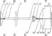
特别申明,在本发明中,采样盒21一端的方向为本发明及其各部件沿水平方向的前端,后抵件抵板1一端的方向为本发明及其各部件沿水平方向的后端。同时,涉及传动手轮5顺时针及逆时针的转动方向时,使用者的视线都是以由本发明的前端朝向后端的方向为准。In particular, in the present invention, the direction of one end of the
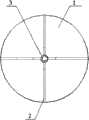
如图1、2、3、6所示,所述的后抵件由后抵件抵板1及后抵件传动杆3组成;所述的后抵件抵板1为圆板,圆柱形的后抵件传动杆3的后端通过四块后抵件加强筋板2与后抵件抵板1焊接连接,前端与内螺纹套筒4的后端通过正螺纹连接;以上部件的协同技术功能是:当后抵件抵板1抵在土壤采样坑的采样面上时,由于采样面的摩擦力或者人为施加外力,如用手扳住后抵件加强筋板2,都可使后抵件不随内螺纹套筒4转动,在这种情况下可使内螺纹套筒4通过手轮5的转动在螺纹带动下前后运动。As shown in Figures 1, 2, 3, and 6, the rear abutment is composed of a
如图1、7所示,所述的传动单元由内螺纹套筒4和传动手轮5组成;传动手轮5与内螺纹套筒4在内螺纹套筒4的中部采用键22连接,内螺纹套筒4的前端内部为反内螺纹,与采样头传动杆13的后端反螺纹连接,内螺纹套筒4的后端内部为正内螺纹,与后抵件传动杆3的前端正螺纹连接;内螺纹套筒4的前端外部焊接有圆管状的前抵件阻块6;以上部件的协同技术功能是:沿逆时针方向转动传动手轮5,通过键22带动内螺纹套筒4转动,当施加外力,使后抵件传动杆3及采样槽16不随内螺纹套筒4转动,那么将使后抵件抵板1与采样头同时沿内螺纹套筒4向两边相对扩张运动;反之,沿顺时针方向转动传动手轮5,当施加外力,使后抵件传动杆3及采样头不随内螺纹套筒4转动,那么将使后抵件抵板1与采样头同时沿内螺纹套筒4向两边相对收缩运动;当后抵件抵板1与采样头前端的采样盒21同时抵紧土壤采样面时,将使后抵件传动杆3及采样头不随内螺纹套筒4转动,同时由于后抵件抵板1与土壤采样面的接触面积大于采样盒21与土壤采样面的接触面积,那么逆时针旋转手轮5必然推动采样盒21及采样槽16进入土壤采样面,进而采集土样。As shown in Figures 1 and 7, the transmission unit is composed of an internally threaded
如图1、2、3、8所示,所述的前抵件包括前抵件抵板11与前抵件紧固件8;前抵件抵板11为两块半圆板;紧固件8为两根对称的半圆形圆管;前抵件连接筋板14为两块L形钢板,两块L形钢板前端分别垂直焊接于前抵件抵板11的半圆板,两块L形钢板后端分别与紧固件8的两根对称的半圆形圆管的脊部垂直焊接;左右对称的L形前抵件连接筋板14内部组成的U形空隙的长度要大于采样头连接筋板12以及采样槽16与土壤样品切具通过切具滑轨18和切具滑轨槽17结合后形成的部件的长度之和,以便留有足够的空间令进入土壤采样面后的采样头可以从采样面拔出;As shown in Figures 1, 2, 3, and 8, the front abutment includes a
所述的紧固件8左右两根对称的半圆形圆管的彼此对接部分两边分别焊接有上下两个正方形片状的前抵件连接耳7,正方形片状的前抵件连接耳7呈两两对应关系,两个对应的前抵件连接耳7的中间开孔有前抵件紧固螺栓15分别从中穿过,将紧固件8锁紧并抵在前抵件阻块6的前端;以上部件的协同技术功能是:当采样槽16没入采样面后,在前抵件阻块6与采样头之间放入前抵件,将两块前抵件抵板11抵在采样面上并在中间预留采样槽16的出土位置,通过前抵件连接耳7及前抵件紧固螺栓15将紧固件8锁紧在前抵件阻块6的前端;当顺时针旋转传动手轮5时,缩短了内螺纹套筒4与采样槽16之间的距离,使前抵件抵板11抵紧采样面,由于前抵件抵板11与采样面作用而提供给采样头的,方向为由前端向后端的作用力大于各采样盒21与采样面的摩擦力,因此不断旋转传动手轮5,没入采样面的采样槽16就会被拔出采样面。The two sides of the two symmetrical semicircular round tubes of the
所述的采样头包括采样头传动杆13、采样槽16、采样盒21及土壤样品切具;Described sampling head comprises sampling
如图1、2、3、9所示,所述的采样槽16为中空长方形箱体,沿水平方向在前端开口,对应未开口的一面的为采样槽16的底面;两块对称的采样头连接筋板12分别与该采样槽16的底面和采样头传动杆13前端焊接;采样头传动杆13为圆柱体,其后端通过反向螺纹与内螺纹套筒4的前端螺纹连接;前抵件长度为前抵件抵板11与前抵件紧固件8两端之间的总长度,采样头传动杆13的总长度要求略长于前抵件长度,便于在内螺纹套筒4与采样槽16之间放入前抵件;As shown in Figures 1, 2, 3, and 9, the
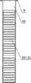
所述的采样槽16前端开口一面被隔成高度为1cm的若干个采样盒室19;采样盒21为沿水平方向前后两端开口的中空长方体,其宽度和高度要求正好放入采样盒室19内;每个采样盒21与采样盒室19的尺寸紧密配合,使采样盒21刚好能够卡入采样室19内部,采样盒21由采样槽16开口端装入;采样盒室19靠近采样槽16底面的部分为采样盒室19的底部,在每个采样盒室19底部上下内壁设有凸出的隔台20,当装入采样盒室19后,在采样盒室19底部与采样盒21间形成空隙;采样盒21与隔台20接触后要露出采样槽16前端开口面的距离3cm;One side of the front end opening of the
设置隔台20的第一个目的是保证原位采样,土壤样品不被压缩;隔台20的设置阻止采样盒21接触到采样盒室19底部,当土样进入采样盒21后,在采样盒室19底部与采样盒21间形成空隙,以便土样进入采样盒21后有一定的缓冲空间,不压缩上样;同时与气孔24配合,达到平衡采样盒21内外气压,保证所采集的土样不被压缩的目的。设置隔台20的第二个目的是方便采样盒21的拿取;隔台20使采样盒21不能完全进入采样盒室19内部,漏出采样槽16前端一部分,这样当采完土样后,可用手捏住采样盒21漏出采样槽16前端部分,轻易拔出;以上部件的协同技术功能是:当采样盒室19中的采样盒21前端抵紧采样面时,采样槽16即不能转动,既限制了采样头传动杆13不能转动;同时,后抵件抵板1抵紧另一采样面,使后抵件传动杆3不能转动,又由于后抵件抵板1的与采样面接触的面积大于各采样盒21前端与采样面接触的面积之和,那么在同时受内螺纹套筒4向外的推动力时,必然推动采样盒室19中的采样盒21抵进采样面。在这种情况下,逆时针转动传动手轮5,向两端推动的力从内螺纹套筒4向两边传动给后抵件及采样头,由于后抵件抵板1与采样盒21都抵紧采样面,那么在螺纹的带动下,能够达到将采样盒室19中的采样盒21抵进采样面的目的。The first purpose of setting the spacer 20 is to ensure in-situ sampling and the soil sample is not compressed; the setting of the spacer 20 prevents the
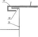
如图3、8所示,所述的采样槽16底面位于采样头连接筋板12两侧开有气孔24,每两个气孔24与一个采样盒室19相通,气孔24与采样盒室19底部依靠隔台20隔成空隙;气孔24与采样盒室19底部依靠隔台20隔成空隙配合,能够达到采样时平衡采样盒室19内外气压,从而达到不对土壤样品压缩及扰动的目的;采样槽16左右面伸出采样槽16底面一部分,沿垂直方向在采样槽16底面两侧形成切具滑轨18,与切具滑轨槽17连接;As shown in Figures 3 and 8, the bottom surface of the
如图5、13所示,所述的采样盒21为沿水平方向前后两端开口的中空长方体,其宽度和高度要求正好放入采样盒室19内,当装入采样盒室19后,要求凸出采样盒室槽16前端开口面的距离3cm;这样方便采样盒21从采样盒室19装入和拿出;采样盒21备有采样盒前盖25与采样盒后盖26,每个采样盒21的盒体两端的形状和尺寸与采样盒前盖25、采样盒后盖26的形状和尺寸要相互配合;使用时将不同的采样盒21、采样盒前盖25与采样盒后盖26分别编号,便于分析土壤不同层次的容重等指标;As shown in Figures 5 and 13, the described
如图1、2、3、8、9所示,土壤样品切具由土壤样品切刀10、切具滑轨槽17、切具阻板23及切具顶盖9组成;As shown in Figures 1, 2, 3, 8, and 9, the soil sample cutter is composed of a
所述的土壤样品切刀10的结构为后端沿垂直方向开口的中空长方体,开口一面沿垂直方向分别设有切具滑轨槽17,与采样槽16上的切具滑轨18连接,控制土壤样品切刀10的前后左右方向,使土壤样品切刀10只能上下移动;土壤样品切刀10上段设有切具阻板23,切具阻板23的高度控制样品切刀10向下使用时深度刚好达到采样槽16最下端的采样盒21为止;切具阻板23的上面是土壤样品切具顶盖9;将土壤样品切具的土壤样品切刀10用力垂直向下压入土壤,能够完全将土壤样品包裹在采样盒21内。The structure of the
本发明的动态工作过程是:Dynamic working process of the present invention is:
1.如图10所示,将后抵件、传动单元、采样头除土壤样品切具外组合在一起,将组合好后的土壤取样器放入事先挖好的约600cm×400cm的长方体采样坑中,坑的深度随采样要求而定,一般要求超过500cm。采样盒21前端对准土壤采样面,顺时针或逆时针旋转传动手轮5,使后抵件抵板1抵紧与采样面对应的采样坑的另一面,并使后抵件及采样槽16不随传动手轮5的转动而转动。继续逆时针旋转传动手轮5,使采样盒21慢慢完全进入采样面的土壤里,停止旋转传动手轮5。1. As shown in Figure 10, assemble the back piece, transmission unit, and sampling head together except the soil sample cutter, and put the assembled soil sampler into a pre-dug cuboid sampling pit of about 600cm×400cm Among them, the depth of the pit depends on the sampling requirements, and generally requires more than 500cm. The front end of the
2.如图11所示,将土壤样品切具前端的切具滑轨槽17底部与切具滑轨18上部连接,用手向下按下或者用胶锤向下砸下土壤切具顶盖9,使土壤样品切刀10进入土壤,直至上层切具阻板23与采样槽16接触,表示土壤样品切刀10已到达采样槽16底端最后一个采样盒21,垂直方向切断了土壤样品,并将土壤样品完全包裹在采样槽16内。2. As shown in Figure 11, connect the bottom of the cutter
3.如图12所示,通过转动传动手轮5来调整前抵件阻块6与采样面之间的距离,直至在前抵件阻块6与采样面之间能够放入前抵件;将前抵件紧固件8抵在前抵件阻块6前端后,并用前抵件紧固螺栓15穿过前抵件连接耳7将左右前抵件紧固件8锁紧。调整左右前抵件抵板11,令其半圆形直边与采样槽16左右面平行,不阻挡采样槽16出土。顺时针旋转传动手轮5,前抵件抵板11慢慢顶紧采样面,采样头慢慢被提拔出土壤采样面;3. As shown in Figure 12, adjust the distance between the
4.如图13所示,沿切具滑轨18长度方向拔出土壤样品切刀10,握紧采样盒21突出采样槽16部分,将其拔出采样槽16,用铲刀等刮平突出采样盒21的土壤样品边缘,盖上采样盒前盖25及后盖26,完成一次采样。4. As shown in Figure 13, pull out the
5.可根据取样要求继续沿采样坑深度方向向下进行采样。5. Sampling can be continued down along the depth direction of the sampling pit according to the sampling requirements.
有益效果:一种土壤采样器,当向一个方向转动传动单元的传动手轮时,通过杠杆作用及正反螺纹传动杆,后抵件和采样头分别得到垂直于手轮方向的向外作用力,因为后抵件抵板与土壤剖面接触面积大于采样头与土壤采样面接触面积,所以后抵件受到阻挡并不随传动单元的转动而转动时,采样头获得向外的推动力,从而使采样头进入采样面采样,当向另一个方向转动传动单元的传动手轮时,利用相似的作用原理及前抵件装置,采样头获得向内的拉力,退出采样面,从而达到省力的目的,可以在较硬的板结土壤中较轻松地取样;采样头设有土壤样品切具,在土壤样品进入采样盒后,利用土壤样品切具将采样盒内的样品与土壤完全分离,保证样品不会滑脱,可以在较松散的、样品难以成型的土壤中采样;采样头设有多个采样盒室,保证土壤样品精细分层,多个样品可同时采取,采样盒室底段留有空隙,同时侧壁有隔台,底部有通气孔,保证采样盒进样时内外气压平衡,土壤不被扰动,实现原位采样;采样盒体积及重量一定,方便土壤样品容重的测定。Beneficial effects: a soil sampler, when the transmission handwheel of the transmission unit is turned in one direction, through the lever action and the positive and negative threaded transmission rod, the rear arrival piece and the sampling head respectively obtain an outward force perpendicular to the direction of the handwheel , because the contact area between the back-arresting plate and the soil profile is greater than the contact area between the sampling head and the soil sampling surface, so when the back-arresting member is blocked and does not rotate with the rotation of the transmission unit, the sampling head obtains an outward driving force, thereby making the sampling When the head enters the sampling surface for sampling, when the transmission handwheel of the transmission unit is turned in the other direction, the sampling head obtains the inward pulling force and exits the sampling surface by using the similar principle of action and the front-arresting device, so as to achieve the purpose of labor saving, which can It is easier to sample in hard compacted soil; the sampling head is equipped with a soil sample cutter. After the soil sample enters the sampling box, the soil sample cutter is used to completely separate the sample in the sampling box from the soil to ensure that the sample will not slip. , it can be sampled in loose soil where the sample is difficult to form; the sampling head is equipped with multiple sampling boxes to ensure that the soil samples are finely layered, and multiple samples can be taken at the same time. There is a gap at the bottom of the sampling box. There is a partition on the wall and a ventilation hole at the bottom to ensure the balance of the internal and external air pressure when the sampling box is injected, and the soil is not disturbed to realize in-situ sampling; the volume and weight of the sampling box are fixed, which is convenient for the determination of the bulk density of soil samples.
附图说明Description of drawings
图1是本发明构成示意图的俯视图。Fig. 1 is a top view of the schematic diagram of the present invention.
图2是本发明构成示意图的主视图。Fig. 2 is a front view of a schematic diagram of the structure of the present invention.
图3是图1的I-I剖面图。Fig. 3 is an I-I sectional view of Fig. 1 .
图4是图1中A的放大图。Fig. 4 is an enlarged view of A in Fig. 1 .
图5是图3中B的放大图。Fig. 5 is an enlarged view of B in Fig. 3 .
图6是图2的II-II剖面图。FIG. 6 is a cross-sectional view of II-II in FIG. 2 .
图7是图2的III-III剖面图。Fig. 7 is a III-III sectional view of Fig. 2 .
图8是图2的IV-IV剖面图。FIG. 8 is a sectional view taken along line IV-IV of FIG. 2 .
图9是图2的V-V剖面图。Fig. 9 is a V-V sectional view of Fig. 2 .
图10是本发明的工作状态示意图之一。Fig. 10 is one of the working state schematic diagrams of the present invention.
图11是本发明的工作状态示意图之二。Fig. 11 is the second schematic diagram of the working state of the present invention.
图12是本发明的工作状态示意图之三。Fig. 12 is the third schematic view of the working state of the present invention.
图13是本发明的工作状态示意图之四。Fig. 13 is the fourth schematic view of the working state of the present invention.
具体实施方式Detailed ways
本发明提供的土壤采样器由后抵件、传动单元、采样头及前抵件组成;The soil sampler provided by the present invention is composed of a rear abutment, a transmission unit, a sampling head and a front abutment;
特别申明,在本发明中,采样盒21一端的方向为本发明及其各部件沿水平方向的前端,后抵件抵板1一端的方向为本发明及其各部件沿水平方向的后端。同时,涉及传动手轮5顺时针及逆时针的转动方向时,使用者的视线都是以由本发明的前端朝向后端的方向为准。In particular, in the present invention, the direction of one end of the
如图1、2、3、6所示,所述的后抵件由后抵件抵板1及后抵件传动杆3组成;所述的后抵件抵板1为圆板,圆柱形的后抵件传动杆3的后端通过四块后抵件加强筋板2与后抵件抵板1焊接连接,前端与内螺纹套筒4的后端通过正螺纹连接;以上部件的协同技术功能是:当后抵件抵板1抵在土壤采样坑的采样面上时,由于采样面的摩擦力或者人为施加外力,如用手扳住后抵件加强筋板2,都可使后抵件不随内螺纹套筒4转动,在这种情况下可使内螺纹套筒4通过手轮5的转动在螺纹带动下前后运动。As shown in Figures 1, 2, 3, and 6, the rear abutment is composed of a
如图1、7所示,所述的传动单元由内螺纹套筒4和传动手轮5组成;传动手轮5与内螺纹套筒4在内螺纹套筒4的中部采用键22连接,内螺纹套筒4的前端内部为反内螺纹,与采样头传动杆13的后端反螺纹连接,内螺纹套筒4的后端内部为正内螺纹,与后抵件传动杆3的前端正螺纹连接;内螺纹套筒4的前端外部焊接有圆管状的前抵件阻块6;以上部件的协同技术功能是:沿逆时针方向转动传动手轮5,通过键22带动内螺纹套筒4转动,当施加外力,使后抵件传动杆3及采样槽16不随内螺纹套筒4转动,那么将使后抵件抵板1与采样头同时沿内螺纹套筒4向两边相对扩张运动;反之,沿顺时针方向转动传动手轮5,当施加外力,使后抵件传动杆3及采样头不随内螺纹套筒4转动,那么将使后抵件抵板1与采样头同时沿内螺纹套筒4向两边相对收缩运动;当后抵件抵板1与采样头前端的采样盒21同时抵紧土壤采样面时,将使后抵件传动杆3及采样头不随内螺纹套筒4转动,同时由于后抵件抵板1与土壤采样面的接触面积大于采样盒21与土壤采样面的接触面积,那么逆时针旋转手轮5必然推动采样盒21及采样槽16进入土壤采样面,进而采集土样。As shown in Figures 1 and 7, the transmission unit is composed of an internally threaded sleeve 4 and a transmission handwheel 5; the middle part of the transmission handwheel 5 and the internally threaded sleeve 4 is connected by a key 22, and the internal The inside of the front end of the threaded sleeve 4 is a reverse internal thread, which is connected with the reverse thread at the rear end of the sampling head transmission rod 13; connection; the front end of the internally threaded sleeve 4 is welded with a circular tubular front block 6; the collaborative technical function of the above components is: rotate the transmission handwheel 5 in the counterclockwise direction, and drive the internally threaded sleeve 4 to rotate through the key 22 , when an external force is applied so that the rear-arriving member transmission rod 3 and the sampling groove 16 do not rotate with the internal thread sleeve 4, then the rear-arriving member abutment plate 1 and the sampling head will expand and move relatively to both sides along the internal thread sleeve 4 at the same time; otherwise , turn the transmission handwheel 5 clockwise, when an external force is applied so that the transmission rod 3 and the sampling head do not rotate with the internal thread sleeve 4, then the rear arrival plate 1 and the sampling head will move along the internal thread sleeve at the same time.
如图1、2、3、8所示,所述的前抵件包括前抵件抵板11与前抵件紧固件8;前抵件抵板11为两块半圆板;紧固件8为两根对称的半圆形圆管;前抵件连接筋板14为两块L形钢板,两块L形钢板前端分别垂直焊接于前抵件抵板11的半圆板,两块L形钢板后端分别与紧固件8的两根对称的半圆形圆管的脊部垂直焊接;左右对称的L形前抵件连接筋板14内部组成的U形空隙的长度要大于采样头连接筋板12以及采样槽16与土壤样品切具通过切具滑轨18和切具滑轨槽17结合后形成的部件的长度之和,以便留有足够的空间令进入土壤采样面后的采样头可以从采样面拔出;As shown in Figures 1, 2, 3, and 8, the front abutment includes a
所述的紧固件8左右两根对称的半圆形圆管的彼此对接部分两边分别焊接有上下两个正方形片状的前抵件连接耳7,正方形片状的前抵件连接耳7呈两两对应关系,两个对应的前抵件连接耳7的中间开孔有前抵件紧固螺栓15分别从中穿过,将紧固件8锁紧并抵在前抵件阻块6的前端;以上部件的协同技术功能是:当采样槽16没入采样面后,在前抵件阻块6与采样头之间放入前抵件,将两块前抵件抵板11抵在采样面上并在中间预留采样槽16的出土位置,通过前抵件连接耳7及前抵件紧固螺栓15将紧固件8锁紧在前抵件阻块6的前端;当顺时针旋转传动手轮5时,缩短了内螺纹套筒4与采样槽16之间的距离,使前抵件抵板11抵紧采样面,由于前抵件抵板11与采样面作用而提供给采样头的,方向为由前端向后端的作用力大于各采样盒21与采样面的摩擦力,因此不断旋转传动手轮5,没入采样面的采样槽16就会被拔出采样面。The two sides of the two symmetrical semicircular round tubes of the
所述的采样头包括采样头传动杆13、采样槽16、采样盒21及土壤样品切具;Described sampling head comprises sampling
如图1、2、3、9所示,所述的采样槽16为中空长方形箱体,沿水平方向在前端开口,对应未开口的一面的为采样槽16的底面;两块对称的采样头连接筋板12分别与该采样槽16的底面和采样头传动杆13前端焊接;采样头传动杆13为圆柱体,其后端通过反向螺纹与内螺纹套筒4的前端螺纹连接;前抵件长度为前抵件抵板11与前抵件紧固件8两端之间的总长度,采样头传动杆13的总长度要求略长于前抵件长度,便于在内螺纹套筒4与采样槽16之间放入前抵件;As shown in Figures 1, 2, 3, and 9, the
所述的采样槽16前端开口一面被隔成高度为1cm的若干个采样盒室19;采样盒21为沿水平方向前后两端开口的中空长方体,其宽度和高度要求正好放入采样盒室19内;每个采样盒21与采样盒室19的尺寸紧密配合,使采样盒21刚好能够卡入采样室19内部,采样盒21由采样槽16开口端装入;采样盒室19靠近采样槽16底面的部分为采样盒室19的底部,在每个采样盒室19底部上下内壁设有凸出的隔台20,当装入采样盒室19后,在采样盒室19底部与采样盒21间形成空隙;采样盒21与隔台20接触后要露出采样槽16前端开口面的距离3cm;One side of the front end opening of the
设置隔台20的第一个目的是保证原位采样,土壤样品不被压缩;隔台20的设置阻止采样盒21接触到采样盒室19底部,当土样进入采样盒21后,在采样盒室19底部与采样盒21间形成空隙,以便土样进入采样盒21后有一定的缓冲空间,不压缩土样;同时与气孔24配合,达到平衡采样盒21内外气压,保证所采集的土样不被压缩的目的。设置隔台20的第二个目的是方便采样盒21的拿取;隔台20使采样盒21不能完全进入采样盒室19内部,漏出采样槽16前端一部分,这样当采完土样后,可用手捏住采样盒21漏出采样槽16前端部分,轻易拔出;以上部件的协同技术功能是:当采样盒室19中的采样盒21前端抵紧采样面时,采样槽16即不能转动,既限制了采样头传动杆13不能转动;同时,后抵件抵板1抵紧另一采样面,使后抵件传动杆3不能转动,又由于后抵件抵板1的与采样面接触的面积大于各采样盒21前端与采样面接触的面积之和,那么在同时受内螺纹套筒4向外的推动力时,必然推动采样盒室19中的采样盒21抵进采样面。在这种情况下,逆时针转动传动手轮5,向两端推动的力从内螺纹套筒4向两边传动给后抵件及采样头,由于后抵件抵板1与采样盒21都抵紧采样面,那么在螺纹的带动下,能够达到将采样盒室19中的采样盒21抵进采样面的目的。The first purpose of setting the spacer 20 is to ensure in-situ sampling and the soil sample is not compressed; the setting of the spacer 20 prevents the
如图3、8所示,所述的采样槽16底面位于采样头连接筋板12两侧开有气孔24,每两个气孔24与一个采样盒室19相通,气孔24与采样盒室19底部依靠隔台20隔成空隙;气孔24与采样盒室19底部依靠隔台20隔成空隙配合,能够达到采样时平衡采样盒室19内外气压,从而达到不对土壤样品压缩及扰动的目的;采样槽16左右面伸出采样槽16底面一部分,沿垂直方向在采样槽16底面两侧形成切具滑轨18,与切具滑轨槽17连接;As shown in Figures 3 and 8, the bottom surface of the
如图5、13所示,所述的采样盒21为沿水平方向前后两端开口的中空长方体,其宽度和高度要求正好放入采样盒室19内,当装入采样盒室19后,要求凸出采样盒室槽16前端开口面的距离3cm;这样方便采样盒21从采样盒室19装入和拿出;采样盒21备有采样盒前盖25与采样盒后盖26,每个采样盒21的盒体两端的形状和尺寸与采样盒前盖25、采样盒后盖26的形状和尺寸要相互配合;使用时将不同的采样盒21、采样盒前盖25与采样盒后盖26分别编号,便于分析土壤不同层次的容重等指标;As shown in Figures 5 and 13, the described
如图1、2、3、8、9所示,土壤样品切具由土壤样品切刀10、切具滑轨槽17、切具阻板23及切具顶盖9组成;As shown in Figures 1, 2, 3, 8, and 9, the soil sample cutter is composed of a
所述的土壤样品切刀10的结构为后端沿垂直方向开口的中空长方体,开口一面沿垂直方向分别设有切具滑轨槽17,与采样槽16上的切具滑轨18连接,控制土壤样品切刀10的前后左右方向,使土壤样品切刀10只能上下移动;土壤样品切刀10上段设有切具阻板23,切具阻板23的高度控制样品切刀10向下使用时深度刚好达到采样槽16最下端的采样盒21为止;切具阻板23的上面是土壤样品切具顶盖9;将土壤样品切具的土壤样品切刀10用力垂直向下压入土壤,能够完全将土壤样品包裹在采样盒21内。The structure of the
本发明整体为不锈钢材料制作。采样槽16、采样盒室19、采样盒21、采样盒前盖25、采样盒后盖26以及土壤样品切具壁厚采用0.5mm,便于减少对土壤的扰动,同时达到省力的目的,其他涉及的钢板及钢管壁厚采用2-4mm;后抵件抵板1及前抵件抵板11采用直径300mm的圆板,既满足功能要求又方便携带;后抵件传动杆3长度为200mm,采样头传动杆13长度分别为300mm,螺杆部分分别采用M16-M18正反外螺纹,后抵件传动杆3螺杆部分长度150mm,采样头传动杆13螺杆部分长度250mm,内螺纹套筒4长度为450mm,内部正反内螺纹与后抵件传动杆3及采样头传动杆13螺杆部分长度相当,且满足内螺纹套筒4的正反内螺纹长度分别大于后抵件传动杆3与采样头传动杆13的外螺纹长度50mm左右的条件;手轮200-300mm,中部镂空以减轻重量;前抵件紧固件8的内径与内螺纹套筒4的外径相同,外径与前抵件阻块6的外径相同;采样槽16长×宽×高=100mm×100mm×300mm,土壤样品切刀10内部长×宽×高=100mm×100mm×350mm,采样盒室19长×宽×高=100mm×100mm×10mm,个数为30个;相应的采样盒21高度为10mm,因此,每个采样头采样盒室19及采样盒21为30个,可采样垂直深度为300mm,每使用一次可采1厘米高度定体积样品30个。The present invention is made of stainless steel material as a whole. The wall thickness of
本发明的动态工作过程是:Dynamic working process of the present invention is:
1.如图10所示,将后抵件、传动单元、采样头除土壤样品切具外组合在一起,将组合好后的土壤取样器放入事先挖好的约600cm×400cm的长方体采样坑中,坑的深度随采样要求而定,一般要求超过500cm。采样盒21前端对准土壤采样面,顺时针或逆时针旋转传动手轮5,使后抵件抵板1抵紧与采样面对应的采样坑的另一面,并使后抵件及采样槽16不随传动手轮5的转动而转动。继续逆时针旋转传动手轮5,使采样盒21慢慢完全进入采样面的土壤里,停止旋转传动手轮5。1. As shown in Figure 10, assemble the back piece, transmission unit, and sampling head together except the soil sample cutter, and put the assembled soil sampler into a pre-dug cuboid sampling pit of about 600cm×400cm Among them, the depth of the pit depends on the sampling requirements, and generally requires more than 500cm. The front end of the
2.如图11所示,将土壤样品切具前端的切具滑轨槽17底部与切具滑轨18上部连接,用手向下按下或者用胶锤向下砸下土壤切具顶盖9,使土壤样品切刀10进入土壤,直至上层切具阻板23与采样槽16接触,表示土壤样品切刀10已到达采样槽16底端最后一个采样盒21,垂直方向切断了土壤样品,并将土壤样品完全包裹在采样槽16内。2. As shown in Figure 11, connect the bottom of the cutter
3.如图12所示,通过转动传动手轮5来调整前抵件阻块6与采样面之间的距离,直至在前抵件阻块6与采样面之间能够放入前抵件;将前抵件紧固件8抵在前抵件阻块6前端后,并用前抵件紧固螺栓15穿过前抵件连接耳7将左右前抵件紧固件8锁紧。调整左右前抵件抵板11,令其半圆形直边与采样槽16左右面平行,不阻挡采样槽16出土。顺时针旋转传动手轮5,前抵件抵板11慢慢顶紧采样面,采样头慢慢被提拔出土壤采样面;3. As shown in Figure 12, adjust the distance between the
4.如图13所示,沿切具滑轨18长度方向拔出土壤样品切刀10,握紧采样盒21突出采样槽16部分,将其拔出采样槽16,用铲刀等刮平突出采样盒21的土壤样品边缘,盖上采样盒前盖25及后盖26,完成一次采样。4. As shown in Figure 13, pull out the
5.可根据取样要求继续沿采样坑深度方向向下进行采样。5. Sampling can be continued down along the depth direction of the sampling pit according to the sampling requirements.
Claims (1)
Priority Applications (1)
| Application Number | Priority Date | Filing Date | Title |
|---|---|---|---|
| CN200910067207XACN101592563B (en) | 2009-07-02 | 2009-07-02 | Soil sampler |
Applications Claiming Priority (1)
| Application Number | Priority Date | Filing Date | Title |
|---|---|---|---|
| CN200910067207XACN101592563B (en) | 2009-07-02 | 2009-07-02 | Soil sampler |
Publications (2)
| Publication Number | Publication Date |
|---|---|
| CN101592563Atrue CN101592563A (en) | 2009-12-02 |
| CN101592563B CN101592563B (en) | 2012-01-11 |
Family
ID=41407334
Family Applications (1)
| Application Number | Title | Priority Date | Filing Date |
|---|---|---|---|
| CN200910067207XAExpired - Fee RelatedCN101592563B (en) | 2009-07-02 | 2009-07-02 | Soil sampler |
Country Status (1)
| Country | Link |
|---|---|
| CN (1) | CN101592563B (en) |
Cited By (15)
| Publication number | Priority date | Publication date | Assignee | Title |
|---|---|---|---|---|
| CN101832883A (en)* | 2010-06-02 | 2010-09-15 | 中国科学院遗传与发育生物学研究所 | Soil layering scraping sampler |
| CN102095602A (en)* | 2010-12-30 | 2011-06-15 | 中国科学院东北地理与农业生态研究所 | Soil profile sampler |
| CN102353557A (en)* | 2011-09-22 | 2012-02-15 | 中国科学院东北地理与农业生态研究所 | Cylindrical soil layering apparatus |
| CN102680274A (en)* | 2012-05-25 | 2012-09-19 | 北京卫星制造厂 | End actuating mechanism for sampling extraterrestrial body shallow soil |
| CN102680275A (en)* | 2012-05-25 | 2012-09-19 | 北京卫星制造厂 | Device for sampling shallow soil of extraterrestrial star |
| CN103196697A (en)* | 2013-02-20 | 2013-07-10 | 兰州大学 | Screw type soil-taking and sample-cutting apparatus |
| CN103600359A (en)* | 2013-10-15 | 2014-02-26 | 李培楠 | Fresh and alive tissue section collector |
| CN104089794A (en)* | 2014-07-10 | 2014-10-08 | 浙江大学 | Surface soil sampler capable of controlling sampling quantity |
| CN107063745A (en)* | 2017-05-06 | 2017-08-18 | 宝鸡文理学院 | A kind of soil sample collecting device |
| CN107219088A (en)* | 2017-06-01 | 2017-09-29 | 兰州大学 | A kind of original state meadow sample sampler |
| CN108593331A (en)* | 2018-03-02 | 2018-09-28 | 皮玉辉 | A kind of alkaline land soil stratified sampler |
| CN110501184A (en)* | 2019-07-24 | 2019-11-26 | 华中农业大学 | An undisturbed soil sampling device |
| CN111021950A (en)* | 2019-12-23 | 2020-04-17 | 哈尔滨工程大学 | Ice core drill for on-site ice core slice taking |
| CN113155512A (en)* | 2020-12-30 | 2021-07-23 | 江苏华创环境修复有限公司 | Handheld undisturbed soil sampling device under complex terrain environment |
| CN114608864A (en)* | 2022-03-07 | 2022-06-10 | 中国矿业大学(北京) | Tectonic coal directional sample sampling device, sampling method and test method |
Family Cites Families (1)
| Publication number | Priority date | Publication date | Assignee | Title |
|---|---|---|---|---|
| CN201548418U (en)* | 2009-07-02 | 2010-08-11 | 中国科学院东北地理与农业生态研究所 | Soil sampler |
- 2009
- 2009-07-02CNCN200910067207XApatent/CN101592563B/ennot_activeExpired - Fee Related
Cited By (23)
| Publication number | Priority date | Publication date | Assignee | Title |
|---|---|---|---|---|
| CN101832883A (en)* | 2010-06-02 | 2010-09-15 | 中国科学院遗传与发育生物学研究所 | Soil layering scraping sampler |
| CN102095602A (en)* | 2010-12-30 | 2011-06-15 | 中国科学院东北地理与农业生态研究所 | Soil profile sampler |
| CN102095602B (en)* | 2010-12-30 | 2015-12-16 | 中国科学院东北地理与农业生态研究所 | A Soil Profile Sampler |
| CN102353557A (en)* | 2011-09-22 | 2012-02-15 | 中国科学院东北地理与农业生态研究所 | Cylindrical soil layering apparatus |
| CN102680275B (en)* | 2012-05-25 | 2014-11-19 | 北京卫星制造厂 | Device for sampling shallow soil of extraterrestrial star |
| CN102680274A (en)* | 2012-05-25 | 2012-09-19 | 北京卫星制造厂 | End actuating mechanism for sampling extraterrestrial body shallow soil |
| CN102680275A (en)* | 2012-05-25 | 2012-09-19 | 北京卫星制造厂 | Device for sampling shallow soil of extraterrestrial star |
| CN103196697A (en)* | 2013-02-20 | 2013-07-10 | 兰州大学 | Screw type soil-taking and sample-cutting apparatus |
| CN103196697B (en)* | 2013-02-20 | 2015-12-09 | 兰州大学 | A kind of screw fetches earth and cuts sampling device |
| CN103600359A (en)* | 2013-10-15 | 2014-02-26 | 李培楠 | Fresh and alive tissue section collector |
| CN104089794B (en)* | 2014-07-10 | 2016-08-24 | 浙江大学 | A kind of topsoil sampler of controlled sampling quantity |
| CN104089794A (en)* | 2014-07-10 | 2014-10-08 | 浙江大学 | Surface soil sampler capable of controlling sampling quantity |
| CN107063745A (en)* | 2017-05-06 | 2017-08-18 | 宝鸡文理学院 | A kind of soil sample collecting device |
| CN107063745B (en)* | 2017-05-06 | 2019-06-25 | 宝鸡文理学院 | A kind of soil sample acquisition equipment |
| CN107219088B (en)* | 2017-06-01 | 2023-10-10 | 兰州大学 | An undisturbed grassland sample sampling device |
| CN107219088A (en)* | 2017-06-01 | 2017-09-29 | 兰州大学 | A kind of original state meadow sample sampler |
| CN108593331A (en)* | 2018-03-02 | 2018-09-28 | 皮玉辉 | A kind of alkaline land soil stratified sampler |
| CN110501184A (en)* | 2019-07-24 | 2019-11-26 | 华中农业大学 | An undisturbed soil sampling device |
| CN111021950A (en)* | 2019-12-23 | 2020-04-17 | 哈尔滨工程大学 | Ice core drill for on-site ice core slice taking |
| CN111021950B (en)* | 2019-12-23 | 2021-02-02 | 哈尔滨工程大学 | Ice core drill for on-site ice core slice taking |
| CN113155512A (en)* | 2020-12-30 | 2021-07-23 | 江苏华创环境修复有限公司 | Handheld undisturbed soil sampling device under complex terrain environment |
| CN114608864A (en)* | 2022-03-07 | 2022-06-10 | 中国矿业大学(北京) | Tectonic coal directional sample sampling device, sampling method and test method |
| CN114608864B (en)* | 2022-03-07 | 2023-03-10 | 中国矿业大学(北京) | Tectonic coal directional sample sampling device, sampling method and testing method |
Also Published As
| Publication number | Publication date |
|---|---|
| CN101592563B (en) | 2012-01-11 |
Similar Documents
| Publication | Publication Date | Title |
|---|---|---|
| CN101592563B (en) | Soil sampler | |
| CN201548418U (en) | Soil sampler | |
| CN102095602B (en) | A Soil Profile Sampler | |
| CN107290174A (en) | New water sample bed mud combined sampling device and its method for sampling | |
| CN101545831A (en) | Original-state soil sampler | |
| CN104390810B (en) | Novel cutting ring capable of acquiring continuous soil column sample | |
| CN105388040B (en) | A kind of soil sampler | |
| CN102353557A (en) | Cylindrical soil layering apparatus | |
| CN111855266B (en) | A sediment sampler | |
| CN209356239U (en) | A coastal wetland ecological soil sampling device | |
| CN207556917U (en) | A kind of sampling apparatus of sewage disposal water resource | |
| CN104316359B (en) | A kind of multilamellar water sampler | |
| CN204008195U (en) | A kind of biological breadcrust soil sampling apparatus and sampling system | |
| CN202372364U (en) | Multifunctional soil collector | |
| CN203929435U (en) | A kind of foot-operated compressed soil-sampling tool | |
| CN210293752U (en) | A portable sampler for collecting wetland undisturbed soil | |
| CN204165780U (en) | The moisture apparatus for sampling powder material of a kind of different depth | |
| CN109622157B (en) | Combined garbage disposal equipment | |
| CN202174449U (en) | Explorator loading and unloading device for universal sampling machine | |
| CN207779725U (en) | Manpower hammers soil sampler | |
| CN203977402U (en) | Manipulated soil vacuum preloading equipment | |
| CN205642886U (en) | Soil surface soil stratified sampling ware | |
| CN220650086U (en) | A triaxial sampling device for original soil | |
| CN203614040U (en) | a core drill | |
| CN208688854U (en) | A kind of soil borrow ring cutter for karst mountain belt positioning device |
Legal Events
| Date | Code | Title | Description |
|---|---|---|---|
| C06 | Publication | ||
| PB01 | Publication | ||
| C10 | Entry into substantive examination | ||
| SE01 | Entry into force of request for substantive examination | ||
| C14 | Grant of patent or utility model | ||
| GR01 | Patent grant | ||
| CF01 | Termination of patent right due to non-payment of annual fee | Granted publication date:20120111 Termination date:20140702 | |
| EXPY | Termination of patent right or utility model |