CN101589301A - Apparatus and methods for enhancing optical coherence tomography imaging using volumetric filtering techniques - Google Patents
Apparatus and methods for enhancing optical coherence tomography imaging using volumetric filtering techniquesDownload PDFInfo
- Publication number
- CN101589301A CN101589301ACN200780031332.4ACN200780031332ACN101589301ACN 101589301 ACN101589301 ACN 101589301ACN 200780031332 ACN200780031332 ACN 200780031332ACN 101589301 ACN101589301 ACN 101589301A
- Authority
- CN
- China
- Prior art keywords
- electromagnetic radiation
- cross
- sample
- axis
- pattern
- Prior art date
- Legal status (The legal status is an assumption and is not a legal conclusion. Google has not performed a legal analysis and makes no representation as to the accuracy of the status listed.)
- Granted
Links
Images


Classifications
- A—HUMAN NECESSITIES
- A61—MEDICAL OR VETERINARY SCIENCE; HYGIENE
- A61B—DIAGNOSIS; SURGERY; IDENTIFICATION
- A61B3/00—Apparatus for testing the eyes; Instruments for examining the eyes
- A61B3/10—Objective types, i.e. instruments for examining the eyes independent of the patients' perceptions or reactions
- A61B3/12—Objective types, i.e. instruments for examining the eyes independent of the patients' perceptions or reactions for looking at the eye fundus, e.g. ophthalmoscopes
- A61B3/1225—Objective types, i.e. instruments for examining the eyes independent of the patients' perceptions or reactions for looking at the eye fundus, e.g. ophthalmoscopes using coherent radiation
- A—HUMAN NECESSITIES
- A61—MEDICAL OR VETERINARY SCIENCE; HYGIENE
- A61B—DIAGNOSIS; SURGERY; IDENTIFICATION
- A61B5/00—Measuring for diagnostic purposes; Identification of persons
- A61B5/0059—Measuring for diagnostic purposes; Identification of persons using light, e.g. diagnosis by transillumination, diascopy, fluorescence
- A61B5/0062—Arrangements for scanning
- A61B5/0066—Optical coherence imaging
- A—HUMAN NECESSITIES
- A61—MEDICAL OR VETERINARY SCIENCE; HYGIENE
- A61B—DIAGNOSIS; SURGERY; IDENTIFICATION
- A61B5/00—Measuring for diagnostic purposes; Identification of persons
- A61B5/68—Arrangements of detecting, measuring or recording means, e.g. sensors, in relation to patient
- A61B5/6846—Arrangements of detecting, measuring or recording means, e.g. sensors, in relation to patient specially adapted to be brought in contact with an internal body part, i.e. invasive
- A61B5/6847—Arrangements of detecting, measuring or recording means, e.g. sensors, in relation to patient specially adapted to be brought in contact with an internal body part, i.e. invasive mounted on an invasive device
- A61B5/6852—Catheters
- A—HUMAN NECESSITIES
- A61—MEDICAL OR VETERINARY SCIENCE; HYGIENE
- A61B—DIAGNOSIS; SURGERY; IDENTIFICATION
- A61B5/00—Measuring for diagnostic purposes; Identification of persons
- A61B5/0059—Measuring for diagnostic purposes; Identification of persons using light, e.g. diagnosis by transillumination, diascopy, fluorescence
- A61B5/0073—Measuring for diagnostic purposes; Identification of persons using light, e.g. diagnosis by transillumination, diascopy, fluorescence by tomography, i.e. reconstruction of 3D images from 2D projections
Landscapes
- Health & Medical Sciences (AREA)
- Life Sciences & Earth Sciences (AREA)
- Medical Informatics (AREA)
- Molecular Biology (AREA)
- Veterinary Medicine (AREA)
- Biophysics (AREA)
- Public Health (AREA)
- Engineering & Computer Science (AREA)
- Biomedical Technology (AREA)
- Heart & Thoracic Surgery (AREA)
- General Health & Medical Sciences (AREA)
- Physics & Mathematics (AREA)
- Surgery (AREA)
- Animal Behavior & Ethology (AREA)
- Pathology (AREA)
- Nuclear Medicine, Radiotherapy & Molecular Imaging (AREA)
- Radiology & Medical Imaging (AREA)
- Ophthalmology & Optometry (AREA)
- Investigating Or Analysing Materials By Optical Means (AREA)
- Length Measuring Devices By Optical Means (AREA)
Abstract
Translated fromChinese
Description
Translated fromChinese相关申请的交叉引用Cross References to Related Applications
本申请要求序列号为No.60/840,213,提交于2006年8月25日的美国专利申请的优先权,其全部公开通过引用合并于此。This application claims priority to US Patent Application Serial No. 60/840,213, filed August 25, 2006, the entire disclosure of which is hereby incorporated by reference.
技术领域technical field
本发明涉及用于增强光学相干断层成像的装置和方法,尤其涉及这样的装置和方法:其能够使用对可以用来生成这些图像的测量数据采用三维(例如体积测定(volumetric))过滤的技术来增强光学相干断层图像的对比度。The present invention relates to devices and methods for enhanced optical coherence tomography, and in particular to devices and methods that can use techniques that employ three-dimensional (e.g. volumetric) filtering of the measurement data that can be used to generate these images to Enhanced contrast in optical coherence tomography images.
背景技术Background technique
使用作为诊断方式的光学相干断层成像(“OCT”)和能够提供至例如2mm深度的组织微观结构的高分辨率横截面图像的技术的潜力已经被广泛重视。然而,在许多临床应用中,传统的OCT技术的诊断能力已经被斑纹噪声的混淆效应所限制。可以是成像分辨率的尺寸比例的大量值幅度噪声的该噪声能够由可以用来提供被评估组织的深度剖面的相干测距技术来产生。某些临床相关的结构,虽然在尺寸上大于~10mm的成像分辨率,但是其可能缺少相对于要通过该斑纹噪声来清楚识别的周围组织的足够的本征光散射对比度。The potential of using optical coherence tomography ("OCT") as a diagnostic modality and a technique capable of providing high resolution cross-sectional images of tissue microstructure down to a depth of eg 2 mm has been widely appreciated. However, in many clinical applications, the diagnostic capabilities of conventional OCT techniques have been limited by the confounding effects of speckle noise. This noise, which may be large-valued magnitude noise proportional to the size of the imaging resolution, can be generated by coherent ranging techniques that may be used to provide a depth profile of the tissue being assessed. Certain clinically relevant structures, although larger than ~10mm imaging resolution in size, may lack sufficient intrinsic light-scattering contrast with respect to surrounding tissue to be clearly identified by this speckle noise.
所提出的用于减轻斑纹噪声影响的方法可以被分类为物理组合方法或数字处理方法。例如,物理组合方法通常通过结合对所分析的组织的同一位置进行的多个斑纹非相关的测量来起作用。该方法的实现可以要求对成像系统的修改,该修改可能使导管的设计和侵入性最小的探测器的设计变得复杂。这些物理组合方法的实例可以包括角度组合、频率组合、以及偏振组合(例如偏振分集检测)。相反,数字处理方法传统上已经使用目的在于优选地去除斑纹噪声同时保护与组织结构相关的某些特征的过程或滤波器而被完全应用于二维图像。该技术包括自适应滤波、调整、以及小波诊断。然而,与组合方法不同的是,数字处理方法可能局限于原始斑纹图像中包含的信息内容。对于数字处理方法来说重要的是优于OCT的经验执行器(experience implementer)的主要能力,以便于在视觉上过滤噪声和辨别下层组织结构。The proposed methods for mitigating the effects of speckle noise can be classified as physical combination methods or digital processing methods. For example, physical combination methods typically work by combining multiple speckle-uncorrelated measurements taken at the same location in the tissue being analyzed. Implementation of this method may require modifications to the imaging system, which may complicate the design of the catheter and the design of a minimally invasive detector. Examples of these physical combining methods may include angular combining, frequency combining, and polarization combining (eg, polarization diversity detection). In contrast, digital processing methods have traditionally been fully applied to two-dimensional images using processes or filters aimed at preferentially removing speckle noise while preserving certain features related to tissue structures. The technique includes adaptive filtering, scaling, and wavelet diagnostics. However, unlike combined methods, digital processing methods may be limited to the information content contained in the original speckle image. Important for digital processing methods is the primary ability of the experience implementer over OCT to visually filter noise and discern underlying tissue structures.
然而,如果数字处理方法扩展为以三维形式对体积测定OCT数据集进行操作,则这些限制可能不适用。OCT成像速度上的一些改进已经使得使用OCT方法和系统的体积测定成像的实际临床执行得以实现。这样,现在存在采用这些方法和系统作为用于全面疾病检查的工具的潜在临床动机。由于这些三维数据集可能不是直接可见的,因此可以根据从数据集分割的一个或更多个图像典型地进行诊断。优选地,这些分割的图像可以对来自剖面内(例如平面中测量)的测量信息和来自剖面之外(例如平面外测量)的临近位置的测量信息这两者进行合并。However, these limitations may not apply if digital processing methods are extended to operate on volumetric OCT datasets in three dimensions. Several improvements in OCT imaging speed have enabled practical clinical implementation of volumetric imaging using OCT methods and systems. As such, there now exists a potential clinical motivation to employ these methods and systems as tools for comprehensive disease screening. Since these three-dimensional datasets may not be directly visible, a diagnosis can typically be made from one or more images segmented from the dataset. Preferably, these segmented images may incorporate both measurement information from within the profile (eg in-plane measurements) and from nearby locations outside the profile (eg out-of-plane measurements).
实际上,可能需要克服与上述传统设备和方法相关的至少一些不足。例如,这可以通过在数据集分割之前进行数据集的体积测定过滤来实现。因为该示例性的过程可以通过包含平面外测量来增加结果图像的信息内容,所以可以实现实质性的增强。Indeed, it may be desirable to overcome at least some of the disadvantages associated with the conventional apparatus and methods described above. This can be achieved, for example, by volumetric filtering of the dataset prior to dataset segmentation. Substantial enhancements can be achieved because this exemplary procedure can increase the information content of the resulting image by including out-of-plane measurements.
发明内容Contents of the invention
为了解决和/或克服至少一些上述问题和/或不足,可以提供装置和方法的示例性实施例,其能够使用对可以用来生成这些图像的测量数据采用三维(例如体积测定)过滤的技术来增强光学相干断层图像的对比度。To address and/or overcome at least some of the above-mentioned problems and/or deficiencies, exemplary embodiments of apparatus and methods may be provided that are capable of using techniques that employ three-dimensional (e.g., volumetric) filtering of measurement data that may be used to generate these images. Enhanced contrast in optical coherence tomography images.
根据本发明的示例性实施例,可以以三维形式过滤数据集,使得可以生成增强的图像。在本发明的第一示例性实施例中,在对组织的特定截面成像之前,可以对三维OCT数据集应用非对称体积测定中值过滤。在该示例性实施例中,相对于平面内尺度的图像部分,过滤核心在平面外的尺度可以更大。在本发明的第二示例性实施例中,可以提供OCT成像系统,其可以被配置成产生抖动光束扫描图案,以使得在存在实质采样动作的情况下,体积测定成像能够被高保真地执行。利用抖动光束获得的对于该数据集的适当的过滤使得能够产生增强的二维图像。According to an exemplary embodiment of the present invention, data sets may be filtered in three dimensions such that enhanced images may be generated. In a first exemplary embodiment of the invention, an asymmetric volumetric median filter may be applied to a three-dimensional OCT dataset prior to imaging a specific section of tissue. In this exemplary embodiment, the out-of-plane scale of the filter kernel may be larger relative to the image portion of the in-plane scale. In a second exemplary embodiment of the present invention, an OCT imaging system may be provided which may be configured to generate a dithered beam scan pattern such that volumetric imaging can be performed with high fidelity in the presence of substantial sampling action. Appropriate filtering of this data set obtained with a dithered beam enables enhanced two-dimensional images to be produced.
因此,至少出于这些原因,可以提供根据本发明的装置和方法的示例性实施例。例如,可以提供至少一个第一光纤设备和至少一个第二光纤设备(这些光纤设备中的每个具有光传输特性)。第一光纤设备可以被配置成通过其传送至少一个电磁辐射,并将该至少一个电磁辐射转发到至少一个样本。第二光纤可以被配置成通过其传送至少一个从该样本接收到的电磁辐射,并可以将第一光纤设备的至少一部分容纳于其中。Therefore, for at least these reasons, exemplary embodiments of apparatuses and methods according to the present invention may be provided. For example, at least one first fiber optic device and at least one second fiber optic device (each of which fiber optic devices having light transmission properties) may be provided. The first fiber optic device may be configured to transmit at least one electromagnetic radiation therethrough and to forward the at least one electromagnetic radiation to at least one sample. The second optical fiber can be configured to transmit therethrough at least one electromagnetic radiation received from the sample, and can house at least a portion of the first fiber optic device therein.
根据本发明的另一个示例性实施例,第一光纤设备和第二光纤设备各自可以是光纤。使用第一过滤设备和第二过滤设备中的至少一个可以对第一光纤和第二光纤进行过滤,以便防止在其中转发各传送和接收的具有特定波长的电磁辐射中的每个的至少一部分。此外,接收的电磁辐射可以是与样本相关的拉曼辐射。According to another exemplary embodiment of the present invention, each of the first fiber optic device and the second fiber optic device may be an optical fiber. The first optical fiber and the second optical fiber may be filtered using at least one of the first filtering device and the second filtering device to prevent at least a portion of each of the transmitted and received electromagnetic radiation having a particular wavelength from being forwarded therein. Additionally, the received electromagnetic radiation may be Raman radiation associated with the sample.
另外,根据本发明的特定的示例性实施例,可以提供装置和方法,而包括至少一个第一电磁辐射的特定辐射可以被导向至少一个样本,至少一个第二电磁辐射可以被导向参考。具有特定横截面宽度的第一电磁辐射可以被施加到样本的至少一个部分,以产生至少一个第三电磁辐射。可以沿特定轴线在特定横截面宽度的0.5到100的倍数之间的距离内在该部分中提供第一电磁辐射。可以检测与第一电磁辐射相关的第三电磁辐射和与第二电磁辐射相关的至少一个第四电磁辐射之间的干涉。此外,可以提供第一电磁辐射的非对称横截面区域。Furthermore, according to certain exemplary embodiments of the present invention, apparatus and methods may be provided whereby specific radiation comprising at least one first electromagnetic radiation may be directed at at least one sample and at least one second electromagnetic radiation may be directed at a reference. A first electromagnetic radiation having a specific cross-sectional width may be applied to at least a portion of the sample to generate at least one third electromagnetic radiation. The first electromagnetic radiation may be provided in the portion along the particular axis within a distance between 0.5 and 100 multiples of the particular cross-sectional width. Interference between a third electromagnetic radiation associated with the first electromagnetic radiation and at least one fourth electromagnetic radiation associated with the second electromagnetic radiation may be detected. Furthermore, an asymmetrical cross-sectional area of the first electromagnetic radiation may be provided.
根据本发明的再一个示例性实施例,倍数的上限可以是特定横截面宽度的50、60、70、80和/或90倍。在该部分中的第一电磁辐射可以沿不同于所述特定轴线的另一个轴线转换。与至少一个部分相关的至少一个图像可以作为干涉的函数来生成。在该部分中第一电磁辐射可以转换为正弦图案、三角形图案、锯齿形图案和/或螺旋形图案。According to yet another exemplary embodiment of the present invention, the upper limit of the multiple may be 50, 60, 70, 80 and/or 90 times the specific cross-sectional width. The first electromagnetic radiation in this portion may be transformed along another axis than said particular axis. At least one image associated with at least one portion may be generated as a function of the interference. In this portion the first electromagnetic radiation may be converted into a sinusoidal pattern, a triangular pattern, a zigzag pattern and/or a helical pattern.
在本发明的又一个示例性实施例中,第一电磁辐射可以具有沿特定轴线的特定横截面宽度,该宽度可以大于第一电磁辐射沿任何其它轴的另一个横截面宽度。第一电磁辐射还可以具有沿特定轴线的特定横截面宽度,该宽度是第一电磁辐射沿另一个轴线的另一个横截面宽度的至少2倍。此外,在该部分中第一电磁辐射可以沿另一个轴线转换,且该另一个轴线可以大致垂直于该特定轴线。可以对第一电磁辐射的幅度图形和相位图形进行调制。可以提供空间光调制设备、检流计设备、声光调制设备、波导模式干扰设备和/或非对称波导设备中的至少一种。非对称波导设备可以被配置成传播第一电磁辐射的至少三个正交模式。In yet another exemplary embodiment of the present invention, the first electromagnetic radiation may have a certain cross-sectional width along a certain axis, which may be greater than another cross-sectional width of the first electromagnetic radiation along any other axis. The first electromagnetic radiation may also have a certain cross-sectional width along a certain axis that is at least twice as large as another cross-sectional width of the first electromagnetic radiation along another axis. Furthermore, the first electromagnetic radiation may be transformed along another axis in the portion, and the other axis may be substantially perpendicular to the particular axis. The amplitude pattern and the phase pattern of the first electromagnetic radiation can be modulated. At least one of a spatial light modulation device, a galvanometer device, an acousto-optic modulation device, a waveguide mode interference device and/or an asymmetric waveguide device may be provided. The asymmetric waveguide device may be configured to propagate at least three orthogonal modes of the first electromagnetic radiation.
当阅读了以下对本发明的实施例的详细描述后,结合所附的权利要求,本发明的这些和其它目的、特点和优点将变得明显。These and other objects, features and advantages of the present invention will become apparent when reading the following detailed description of the embodiments of the invention when taken in conjunction with the appended claims.
附图说明Description of drawings
从结合示出本发明的例证性实施例的附图所进行的以下详细描述来看,本发明的其它目的、特点和优点将变得明显,在附图中:Other objects, features and advantages of the present invention will become apparent from the following detailed description taken in conjunction with the accompanying drawings showing exemplary embodiments of the invention, in which:
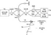
图1是根据本发明的光学频域成像(“OFDI”)系统的示例性实施例的示意性框图,该系统可以用于获取体积测定数据集;1 is a schematic block diagram of an exemplary embodiment of an optical frequency domain imaging ("OFDI") system that may be used to acquire volumetric data sets in accordance with the present invention;
图1B是根据本发明的一个示例性实施例的光栅扫描图案的示例性照射图;FIG. 1B is an exemplary illumination diagram of a raster scan pattern according to an exemplary embodiment of the present invention;
图1C根据本发明的另一个示例性实施例的抖动光束扫描图案的示例性照射图;Figure 1C is an exemplary illumination diagram of a dithered beam scanning pattern according to another exemplary embodiment of the present invention;
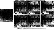
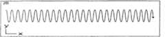
图2A是未过滤的示例性图像;Figure 2A is an exemplary unfiltered image;
图2B是根据本发明的另一个示例性实施例的可以从体积测定中值过滤过程的应用中得到的已被增强的示例性图像集,该图像集具有平面内和平面外尺度上的变化的核心尺寸;FIG. 2B is an example set of images that has been enhanced with variations in in-plane and out-of-plane scales that may result from the application of a volumetric median filtering process, according to another example embodiment of the present invention. core size;
图2C是根据本发明的一个示例性实施例的可以从体积测定中值过滤过程的应用中得到的已被增强的第二示例性图像,该图像具有类似于图2A的核心尺寸的核心尺寸;FIG. 2C is a second exemplary image that has been enhanced, having a kernel size similar to that of FIG. 2A , that may result from the application of a volumetric median filtering process, according to an exemplary embodiment of the present invention;
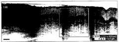
图3A是未应用抖动光束增强的示例性图像;Figure 3A is an exemplary image without dithered beam enhancement applied;
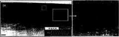
图3B是根据本发明的一个示例性实施例的通过应用具有第一幅度的抖动光束来增强的示例性图像;Figure 3B is an exemplary image enhanced by applying a dithered beam having a first amplitude, according to an exemplary embodiment of the present invention;
图3C是根据本发明的另一个示例性实施例的通过应用具有第一幅度的抖动光束来增强的另一个示例性图像;FIG. 3C is another exemplary image enhanced by applying a dithered beam having a first amplitude, according to another exemplary embodiment of the present invention;
图4A是对根据本发明的一个示例性实施例的第一示例性抖动光束扫描图案的描绘;Figure 4A is a depiction of a first exemplary dithered beam scan pattern according to an exemplary embodiment of the invention;
图4B是对根据本发明的另一个示例性实施例的第二示例性抖动光束扫描图案的描绘;Figure 4B is a depiction of a second exemplary dithered beam scan pattern according to another exemplary embodiment of the present invention;
图4C是对根据本发明的又一个示例性实施例的第三示例性抖动光束扫描图案的描绘;Figure 4C is a depiction of a third exemplary dithered beam scan pattern according to yet another exemplary embodiment of the present invention;
图5A是根据本发明的一个示例性实施例的对称椭圆成像光束图;Figure 5A is a symmetrical elliptical imaging beam diagram according to an exemplary embodiment of the present invention;
图5B是根据本发明的特定示例性实施例的非对称的椭圆成像光束图;Figure 5B is an asymmetric elliptical imaging beam diagram according to certain exemplary embodiments of the present invention;
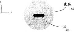
图6A是根据本发明的示例性实施例的示例性非对称波导设备的示意图的正视图,该非对称波导设备可以用于将来自于成像系统的成像光束传送到样本;6A is a front view of a schematic diagram of an exemplary asymmetric waveguide device that may be used to deliver an imaging beam from an imaging system to a sample, according to an exemplary embodiment of the present invention;
图6B是根据本发明的示例性实施例的、可以使用图6A所示光纤的示例性内窥镜光学成像探测器的侧视图;Figure 6B is a side view of an exemplary endoscopic optical imaging probe that may use the optical fiber shown in Figure 6A, according to an exemplary embodiment of the present invention;
图6C是图6B的探测器的示意图的顶视图;Figure 6C is a top view of a schematic diagram of the detector of Figure 6B;
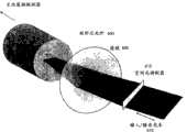
图7是根据本发明的一个示例性实施例的结合旋镜使用矩形芯光纤来减少斑纹的示例性方法的操作图;7 is an operational diagram of an exemplary method of reducing speckle using a rectangular core fiber in conjunction with a rotating mirror, according to an exemplary embodiment of the present invention;
图8是根据本发明的另一个示例性实施例的结合线性空间光调制器使用矩形芯光纤来减少斑纹的另一个示例性方法的操作图;8 is an operational diagram of another exemplary method of reducing speckle using a rectangular core optical fiber in conjunction with a linear spatial light modulator in accordance with another exemplary embodiment of the present invention;
图9是根据本发明的示例性实施例的用于对矩形模式光纤的光相位/幅度图形进行调制的示例性方法的操作图;9 is an operational diagram of an exemplary method for modulating an optical phase/amplitude pattern of a rectangular mode fiber, in accordance with an exemplary embodiment of the present invention;
图10是根据本发明的特定示例性实施例的、用于使用压电致动器(piezo-actuator)以在透镜聚焦之前对光纤进行振动来生成抖动光束扫描的示例性内窥镜成像设备的图。10 is a diagram of an exemplary endoscopic imaging device for generating a dithered beam scan using a piezo-actuator to vibrate an optical fiber prior to lens focusing, according to certain exemplary embodiments of the present invention. picture.
贯穿这些附图,除非另行说明,相同的附图标记和符号用于指示所描述的实施例的同样的特征、元件、部件或部分。此外,由于将参考附图对该主题发明进行详细描述,因此结合所描述的实施例如此执行。对所描述的实施例旨在可以进行变化和修改,而不脱离由所附权利要求限定的主题发明的真实范围和精神。Throughout the drawings, unless otherwise stated, the same reference numerals and symbols are used to refer to the same features, elements, components or parts of the described embodiments. Furthermore, since the subject invention will be described in detail with reference to the drawings, it is thus carried out in conjunction with the described embodiments. It is intended that changes and modifications may be made to the described embodiments without departing from the true scope and spirit of the subject invention as defined by the appended claims.
具体实施方式Detailed ways
图1A示出了根据本发明的示例性实施例的基于光学频域成像(“OFDI”)技术的第二代光学相干断层成像(“OCT”)系统的图。图1A的系统可以利用波长扫频窄带激光源100以使用单元素光接收器来记录作为波长的函数的干涉条纹。虽然图1A所示的示例性系统在这里被描述成能够采用OFDI技术,但是根据本发明的方法和设备的其它示例性实施例可以等同地兼容其它OCT成像系统,包括但不限于时域OCT和谱域OCT技术。FIG. 1A shows a diagram of a second generation optical coherence tomography ("OCT") system based on optical frequency domain imaging ("OFDI") technology according to an exemplary embodiment of the present invention. The system of FIG. 1A can utilize a wavelength-swept
如图1A所示,由源100提供的光或其它电磁辐射可以在分路器105处被分成参考路径106a和样本路径106b。样本路径106a可以通过光学循环器120、二维检流计式反射镜130和聚焦透镜135而被导向样本140。参考光被引导通过参考路径106b,该参考路径106b旨在与样本路径106a的光路长度相匹配。已知某些示例性配置用于实现该功能,包括非反射性路径和图1A中描述的配置,在图1A中描述的配置中,循环器可以用于将参考光引导到可变延迟线115。返回的参考光和样本光在组合器145处彼此干涉。来自组合器145的输出光束可以被导向第一偏振光束分路器(PBS)150a和第二PBS 150b,其各自的输出可以被导向第一平衡接收器155a和第二平衡接收器155b。As shown in FIG. 1A, light or other electromagnetic radiation provided by
传统的处理技术可以用来将所测量的干涉条纹转换为描述样本中的深度分辨反射性的A线。通过使用二维检流计式反射镜130在两个维度扫描成像光束136可以获得示例性图像。例如,可以生成样本140表面上的X-Y平面的任意光束扫描图案。如图1B所示,例如,可以通过沿x方向快速扫描并在y方向针对不同的位移(160a、160b、160c、160d)进行重复来执行体积测定成像技术。可替选地或另外,可以对光束进行抖动,使得该光束在y方向快速振荡,而在x方向165该光束扫描慢得多,如图1C所示。这种示例性扫描技术有助于在三个维度记录图像,并使得能够应用体积测定过滤技术。Conventional processing techniques can be used to convert the measured interference fringes into A-lines that describe the depth-resolved reflectivity in the sample. An exemplary image may be obtained by scanning
图2A示出了在不应用体积测定过滤来说明原始(baseline)图像中的真实斑纹噪声的情况下、使用图1B中描述的扫描图案从数据集获得的示例性的单个横截面图像190(在x-z平面)。图2B和图2C示出了使用图1B的扫描图案从人类皮肤获得的、针对在平面内(x-z)和平面外(y)的维度中操作的不同尺寸的体积测定中值过滤的示例性OFDI图像。FIG. 2A shows an exemplary single cross-sectional image 190 (at x-z plane). 2B and 2C show exemplary OFDI obtained from human skin using the scan pattern of FIG. 1B for volumetric median filtering of different sizes operating in in-plane (x-z) and out-of-plane (y) dimensions. image.
例如,在图2B中示出了包括如图2A中指示的表皮和真皮的分界线的图像的子集中的未经过滤的情况(最左侧的图像191),以及在上排图像192-194中的不经过平面外过滤的、增大平面内过滤核心尺寸的情况。这些示例性结果证明了传统2D中值过滤算法的能力和局限性。伴随着斑纹的减少,这些图像中出现了实质性的模糊。在图2B所示的下排图像195-197中,提供了增加平面外过滤核心尺寸(不经过平面内过滤)的效果。虽然使用的过滤尺寸与在平面内的结果中所使用的尺寸相同,但是可以观察到没有特征模糊的结构可见性的清楚的增强。由于体积测定过滤的使用,这些示例性的结果提供了优选的图像增强的结果,其中体积测定过滤在尺寸上高度不对称,对于图像部分进行平面内的最小过滤和平面外的实质性过滤。图2C示出了基于被评估为产生最佳图像增强的平面内过滤和平面外过滤的结合的示例性横截面图像198。For example, the unfiltered case (leftmost image 191 ) in a subset of images including the demarcation line of the epidermis and dermis as indicated in FIG. 2A is shown in FIG. 2B , and in the upper row of images 192-194 The case of increasing the in-plane filter kernel size without out-of-plane filtering in . These exemplary results demonstrate the capabilities and limitations of traditional 2D median filtering algorithms. Along with the reduction in speckle, there is substantial blurring in these images. In the lower row of images 195-197 shown in Figure 2B, the effect of increasing the out-of-plane filtering kernel size (without in-plane filtering) is provided. Although the same filter size was used as in the in-plane results, a clear enhancement of the visibility of structures without feature ambiguity can be observed. These exemplary results provide preferred image enhancement results due to the use of volumetric filtering, which is highly asymmetric in size, with minimal filtering in-plane and substantial filtering out-of-plane for image parts. FIG. 2C shows an exemplary
图3A示出了在不通过抖动光束扫描(例如,0μm的峰峰抖动幅度)对其进行修正的情况下生成的示例性OFDI图像50、51。图3B和图3C分别示出了根据本发明的示例性实施例的、已经通过应用具有各自不同幅度的抖动光束来增强的示例性图像52、53和54、55。例如,使用抖动光束的扫描可以利用2-D检流计来实现,其y-轴反射镜由500Hz和变化幅度的正弦波形来驱动。利用例如是10kHz的系统A线速率,单个抖动周期可以包含20个特殊的A线。示例性的过滤技术可以通过将获得的数据集组合成一个单独的图像以及应用2D中值过滤来执行。为了确定优选的抖动幅度,可以按例如17.5μm的步长在例如0μm到70μm的峰峰抖动幅度获得对人类体内皮肤的测量。示例性的中值过滤技术可以在产生例如5μm(x方向)乘以例如7.5μm(z)的平面内过滤尺寸以及从0μm到70μm变化的平面外过滤尺寸的单个抖动周期内执行。图3B和图3C示出了针对峰峰抖动幅度分别为35μm和70μm的结果图像52、53和54、55。FIG. 3A shows exemplary OFDI images 50 , 51 generated without correction by dithered beam scanning (eg, peak-to-peak dither amplitude of 0 μm). Figures 3B and 3C illustrate
图4A-4C描绘了根据本发明的示例性实施例的三种示例性抖动扫描图案。例如,图4a示出了示例性的正弦扫描图案200,其包括y方向的快速零均值调制和x方向的缓慢恒速扫描。图4B描绘了示例性的螺旋形扫描图案205,其能够通过以相同或相似的频率、以90度的相位差扫描x方向和y方向同时还包括在x方向的固定速度的缓慢扫描来产生。图4C示出了示例性的斜线扫描图案210,其中y方向由快速锯齿形图案驱动,x方向由缓慢的固定速度扫描来驱动。Y方向位移的范围例如可以是聚焦光束横截面宽度的0.5到100倍。4A-4C depict three exemplary dither scan patterns according to an exemplary embodiment of the present invention. For example, Figure 4a shows an exemplary
图5A描绘了能够利用不同的平面内和平面外分辨率等级来实现对样本的成像的示例性的对称成像光束图形。在图5A中,示出了圆形高斯光束焦点,其中焦点的光束图形300在x(扫描方向)方向和y(平面外维度)方向是对称的。图5B示出了能够实现样本的成像的示例性非对称成像光束图形。在图5B中,可以使用在y方向具有更大延伸的非对称光束图形305。可以使用球形和圆柱形聚焦的光学器件的组合或使用如图6A-6C中描绘的非圆形波导来产生图5B中示出的光束扫描。5A depicts an exemplary symmetrical imaging beam pattern that enables imaging of a sample with different in-plane and out-of-plane resolution levels. In Fig. 5A, a circular Gaussian beam focus is shown, where the
例如,图6A示出了示例性的非对称波导设备,其能够用于将来自成像系统的成像光束传递到样本。例如,该波导设备的芯400(其可以选择性地是玻璃光纤或光子带隙光纤)在一个维度上可以具有相对于另一个维度的更大的范围。该设备的覆层405可以是如图6A所示的圆形或是非对称的形状。结果,使用球形聚焦的光学器件来将该光束成像到样本上可以在样本上产生相似的非对称光束图形。For example, Figure 6A shows an exemplary asymmetric waveguide device that can be used to deliver an imaging beam from an imaging system to a sample. For example, the
图6B示出了根据本发明的示例性实施例的示例性的内窥镜光学成像探测器,其可以使用能够在样本上产生非对称成像光束图形的这种光纤。例如,具有非对称芯410的光纤可以被旋转或被放置在外部驱动轴425内,以增加扭矩传递。在光纤的末端,光可以通过例如是空气或无定形玻璃的部分411而延伸、由透镜415进行聚焦,并通过棱镜420或反射镜向侧面引导。透镜415可以在离开光纤探测器的近似距离Δr处产生聚焦斑点。光纤的角取向使得聚焦光束在Z方向可以大于x方向,如图6B所示。通过旋转光纤或驱动轴425,非对称成像光束可以被转换并有助于对中空器官进行成像。图6C示出了正视图的成像探测器,该正视图示出了x方向的相对于y方向来说的更紧凑的焦点或更小的斑点尺寸。Figure 6B illustrates an exemplary endoscopic optical imaging probe that may use such an optical fiber capable of producing an asymmetric imaging beam pattern on a sample, according to an exemplary embodiment of the present invention. For example, an optical fiber with an asymmetric core 410 can be rotated or placed within an
图7示出了根据本发明的一个示例性实施例的结合旋镜使用矩形芯光纤来减少斑纹的示例性方法的操作图。图7还示出了根据本发明的示例性实施例的设备,其被配置成将来自于系统的成像光束耦合到(例如用于成像的)矩形芯光纤的近端。例如,图7的设备使得光纤远端的成像光束的相位和幅度图形(profile)可以被调制。在该示例性设备中,光纤非对称芯502可以被配置成在芯的具有较大范围的维度中支持多种光模式。通过激励每种模式或这些模式的不同组合,可以获得对反射性的多个测量,每个测量具有去相关的斑纹噪声。这些测量的组合使得可以执行减少斑纹的成像。如图7所示,可以将高斯对称输入光束510从成像系统导向检流计式反射镜515。该反射镜515可以引导光通过透镜505以便聚焦到芯上的矩形范围内的不同的横向位置。通过使检流计式反射镜515倾斜,该芯的被激励的相位/幅度图形可以在近端被调制,因此也可以远端被调制。可以使用与如图6B所示的探测器设计近似的探测器设计来进行内窥镜成像。例如,可以通过相同或相似的光学器件来对返回的光进行重新收集。7 illustrates an operational diagram of an exemplary method of reducing speckle using a rectangular core fiber in conjunction with a rotating mirror, according to an exemplary embodiment of the present invention. Fig. 7 also shows an apparatus according to an exemplary embodiment of the invention configured to couple an imaging beam from the system to the proximal end of a rectangular core optical fiber (eg, for imaging). For example, the device of Figure 7 allows the phase and amplitude profile of an imaging beam at the distal end of an optical fiber to be modulated. In this exemplary device, an optical fiber asymmetric core 502 can be configured to support multiple light modes in the core having a large range of dimensions. By exciting each mode or different combinations of these modes, multiple measurements of reflectivity can be obtained, each with decorrelated speckle noise. The combination of these measurements makes it possible to perform speckle-reduced imaging. As shown in FIG. 7 , a Gaussian symmetric input beam 510 may be directed from an imaging system to a galvanometer mirror 515 . The mirror 515 can direct light through the lens 505 to focus to different lateral positions within a rectangular area on the core. By tilting the galvanometric mirror 515, the excited phase/amplitude pattern of the core can be modulated proximally and thus also distally. Endoscopic imaging can be performed using a detector design similar to that shown in Figure 6B. For example, the returning light can be recollected by the same or similar optics.
图8描绘了根据本发明的示例性实施例的用于调制矩形模式光纤的光相位/幅度图形的示例性方法的操作图,其可以类似于图7所描述的操作图。图8还示出了能够实现该示例性方法的设备的另一个示例性实施例。然而,如图8所示,线性空间光调制器615可以代替检流计式反射镜515。例如,来自系统的输入光束610可以通过线性空间光调制器615,该线性空间光调制器615能够快速变更光束的相位和/或幅度图形。通过透镜605可以将该光聚焦到矩形芯光纤600的芯602上。代替空间光调制器615,可以使用声光调制器或电光调制器来变更光束图形。8 depicts an operational diagram of an exemplary method for modulating an optical phase/amplitude pattern of a rectangular mode fiber, which may be similar to the operational diagram depicted in FIG. 7, in accordance with an exemplary embodiment of the present invention. FIG. 8 also shows another exemplary embodiment of a device capable of implementing the exemplary method. However, as shown in FIG. 8 , a linear spatial
图9示出了根据本发明的示例性实施例的用于调制矩形模式光纤的光相位/幅度图形的示例性方法的操作图。例如,芯702中的光通过光纤的位于硬固定底座705和致动器710之间的部分。致动器710的启动可以产生用于改变光纤内压力的向下或向上的动作,并能够扰动模式图形。致动器710可以选择性地是压电叠层致动器,而芯702相对于致动器的取向可以如图9所示或被旋转。9 illustrates an operational diagram of an exemplary method for modulating an optical phase/amplitude pattern of a rectangular mode fiber, according to an exemplary embodiment of the present invention. For example, light in the core 702 passes through the portion of the fiber between the hard fixed
图10描绘了根据本发明的特定示例性实施例的、用于使用压电致动器小直径内窥镜成像探测器在通过透镜聚焦之前对光纤末端进行振动来生成抖动光束扫描(类似于图4A中所示的图案)的示例性内窥镜成像设备的图。如图10所示,光纤800可以将成像光导向聚焦透镜820。可以利用正弦信号来驱动压电致动器805,使得光纤末梢振动。来自光纤的光可以在空气间隙815延伸、通过透镜820聚焦,并通过棱镜825向侧面引导。作为对光纤末梢进行振动的结果,成像光束830的聚焦斑点可以按指示的抖动图案835振荡。旋转包含在外壳810内的整个导管,可以在内部例如在中空的柱形器官840内对光束进行扫描。10 depicts a method for generating a dithered beam scan (similar to FIG. Diagram of an exemplary endoscopic imaging device for the pattern shown in 4A). As shown in FIG. 10 ,
上述内容仅说明了本发明的原理。鉴于这里所进行的教导,对所描述的实施例的各种修改和改变对于本领域技术人员来说是明显的。实际上,根据本发明的示例性实施例的设备、系统和方法可以结合成像系统来使用,例如结合以下成像系统来使用:在2004年9月8日提交的国际专利申请PCT/US2004/029148、2005年11月2日提交的美国专利申请No.11/266,779以及2004年7月9日提交的美国专利申请No.10/501,276中描述的成像系统。因此可以理解,本领域的技术人员能够设计多种系统、设备和方法,这些系统、设备和方法虽然在这里没有明确地示出或描述,但是体现本发明的原理,且因此在本发明的精神和范围内。另外,就现有技术的知识在上文没有被明确地通过引用合并与此来说,其全部内容被明确地合并与此。这里,在上文所引用的所有公开,其全部内容通过引用合并与此。The foregoing merely illustrates the principles of the invention. Various modifications and alterations to the described embodiments will be apparent to those skilled in the art in view of the teachings presented herein. Indeed, devices, systems and methods according to exemplary embodiments of the present invention may be used in conjunction with imaging systems such as: International Patent Application PCT/US2004/029148, filed September 8, 2004, Imaging systems are described in US Patent Application No. 11/266,779, filed November 2, 2005, and US Patent Application No. 10/501,276, filed July 9, 2004. It will thus be appreciated that those skilled in the art will be able to devise various systems, devices and methods which, although not explicitly shown or described herein, embody the principles of the invention and are therefore within the spirit of the invention and within range. Furthermore, to the extent knowledge of the prior art is not expressly incorporated by reference above, its entire content is hereby expressly incorporated. Here, all publications cited above are hereby incorporated by reference in their entirety.
Claims (17)
Translated fromChineseApplications Claiming Priority (3)
| Application Number | Priority Date | Filing Date | Title |
|---|---|---|---|
| US84021306P | 2006-08-25 | 2006-08-25 | |
| US60/840,213 | 2006-08-25 | ||
| PCT/US2007/076710WO2008024948A2 (en) | 2006-08-25 | 2007-08-24 | Apparatus and methods for enhancing optical coherence tomography imaging using volumetric filtering techniques |
Publications (2)
| Publication Number | Publication Date |
|---|---|
| CN101589301Atrue CN101589301A (en) | 2009-11-25 |
| CN101589301B CN101589301B (en) | 2012-11-07 |
Family
ID=39033720
Family Applications (1)
| Application Number | Title | Priority Date | Filing Date |
|---|---|---|---|
| CN200780031332.4AExpired - Fee RelatedCN101589301B (en) | 2006-08-25 | 2007-08-24 | Apparatus and method for enhancing optical coherence tomography using volumetric filtering techniques |
Country Status (5)
| Country | Link |
|---|---|
| US (1) | US7920271B2 (en) |
| EP (2) | EP3006920A3 (en) |
| JP (2) | JP2010501877A (en) |
| CN (1) | CN101589301B (en) |
| WO (1) | WO2008024948A2 (en) |
Cited By (2)
| Publication number | Priority date | Publication date | Assignee | Title |
|---|---|---|---|---|
| CN114886389A (en)* | 2022-07-14 | 2022-08-12 | 之江实验室 | Three-dimensional photoacoustic/ultrasonic dual-mode endoscope and imaging method |
| JP2023553311A (en)* | 2020-11-27 | 2023-12-21 | アリフ メディカル エルエルシー | Imaging systems, including scanners and modulators, and corresponding methods to improve accuracy |
Families Citing this family (31)
| Publication number | Priority date | Publication date | Assignee | Title |
|---|---|---|---|---|
| JP5538368B2 (en) | 2008-05-15 | 2014-07-02 | アクサン・テクノロジーズ・インコーポレーテッド | OCT coupling probe and integrated system |
| GB0812712D0 (en)* | 2008-07-10 | 2008-08-20 | Imp Innovations Ltd | Improved endoscope |
| US20100253769A1 (en)* | 2008-09-04 | 2010-10-07 | Laser Light Engines | Optical System and Assembly Method |
| EP2462862A4 (en)* | 2009-08-04 | 2016-11-09 | Univ Utsunomiya | DEVICE FOR GENERATING THREE DIMENSIONAL IMAGES OF THE RETINA |
| US10678061B2 (en) | 2009-09-03 | 2020-06-09 | Laser Light Engines, Inc. | Low etendue illumination |
| US11105686B2 (en) | 2010-05-10 | 2021-08-31 | University of Pittshurgh-Of the Commonwealth System of Higher Education | Spatial-domain low-coherence quantitative phase microscopy |
| WO2012100816A1 (en)* | 2011-01-25 | 2012-08-02 | Optopol Technology S.A. | Optical coherence tomography apparatus and method with speckle suppression |
| KR101226442B1 (en)* | 2011-04-08 | 2013-01-28 | 이큐메드 주식회사 | Spectral domain optical coherence tomograpy including of high resolution spectromiter and the method |
| KR101223074B1 (en)* | 2011-06-09 | 2013-01-17 | 광주과학기술원 | Device of optical coherence tomography and method of optical coherence tomography using the same |
| CN102322880B (en)* | 2011-08-18 | 2013-06-05 | 天津大学 | Polarization sensitive distributive optical frequency domain reflection disturbance sensor and demodulation method |
| KR20130099603A (en)* | 2012-02-29 | 2013-09-06 | 삼성테크윈 주식회사 | Spectroscopic inspecting device |
| US8896840B2 (en)* | 2012-04-25 | 2014-11-25 | Canon Kabushiki Kaisha | Interferometric method and digital holographic microscope |
| US9541375B2 (en) | 2012-07-20 | 2017-01-10 | Samsung Electronics Co., Ltd. | Method and apparatus for generating tomography images |
| US9572529B2 (en) | 2012-10-31 | 2017-02-21 | Covidien Lp | Surgical devices and methods utilizing optical coherence tomography (OCT) to monitor and control tissue sealing |
| EP2929327B1 (en) | 2012-12-05 | 2019-08-14 | Perimeter Medical Imaging, Inc. | System and method for wide field oct imaging |
| JP6053138B2 (en)* | 2013-01-24 | 2016-12-27 | 株式会社日立エルジーデータストレージ | Optical tomographic observation apparatus and optical tomographic observation method |
| US8885901B1 (en) | 2013-10-22 | 2014-11-11 | Eyenuk, Inc. | Systems and methods for automated enhancement of retinal images |
| WO2015117241A1 (en)* | 2014-02-05 | 2015-08-13 | British Columbia Cancer Agency Branch | Systems for optical imaging of biological tissues |
| EP4035586A1 (en) | 2015-04-16 | 2022-08-03 | Gentuity LLC | Micro-optic probes for neurology |
| WO2017004555A1 (en)* | 2015-07-01 | 2017-01-05 | The Trustees Of Columbia University In The City Of New York | System, method and computer-accessbile medium for multi-plane imaging of neural circuits |
| US10631718B2 (en) | 2015-08-31 | 2020-04-28 | Gentuity, Llc | Imaging system includes imaging probe and delivery devices |
| US10426326B2 (en)* | 2017-04-19 | 2019-10-01 | Canon U.S.A, Inc. | Fiber optic correction of astigmatism |
| WO2019014767A1 (en) | 2017-07-18 | 2019-01-24 | Perimeter Medical Imaging, Inc. | Sample container for stabilizing and aligning excised biological tissue samples for ex vivo analysis |
| JP7160935B2 (en) | 2017-11-28 | 2022-10-25 | ジェンテュイティ・リミテッド・ライアビリティ・カンパニー | Imaging system |
| CN111819417B (en)* | 2018-03-01 | 2022-03-22 | 爱尔康公司 | Common-path waveguide for stabilizing optical coherence tomography imaging |
| WO2020061001A1 (en) | 2018-09-17 | 2020-03-26 | Gentuity, Llc | Imaging system with optical pathway |
| US10791923B2 (en) | 2018-09-24 | 2020-10-06 | Canon U.S.A., Inc. | Ball lens for optical probe and methods therefor |
| EP3628210A1 (en)* | 2018-09-28 | 2020-04-01 | Paris Sciences et Lettres - Quartier Latin | Methods and systems for in vivo full-field interference microscopy imaging |
| US12364385B2 (en) | 2019-04-30 | 2025-07-22 | Gentuity, Llc | Imaging probe with fluid pressurization element |
| US12239412B2 (en) | 2019-05-21 | 2025-03-04 | Spryte Medical, Inc. | Systems and methods for OCT-guided treatment of a patient |
| KR102284115B1 (en)* | 2019-07-05 | 2021-07-30 | 한국광기술원 | Insertion Type Optical Modulation Apparatus and Method for Attenuating Turbidity of Eyeball |
Family Cites Families (400)
| Publication number | Priority date | Publication date | Assignee | Title |
|---|---|---|---|---|
| US2339754A (en)* | 1941-03-04 | 1944-01-25 | Westinghouse Electric & Mfg Co | Supervisory apparatus |
| US3090753A (en) | 1960-08-02 | 1963-05-21 | Exxon Research Engineering Co | Ester oil compositions containing acid anhydride |
| GB1257778A (en) | 1967-12-07 | 1971-12-22 | ||
| US3601480A (en) | 1968-07-10 | 1971-08-24 | Physics Int Co | Optical tunnel high-speed camera system |
| JPS4932484U (en) | 1972-06-19 | 1974-03-20 | ||
| US3872407A (en)* | 1972-09-01 | 1975-03-18 | Us Navy | Rapidly tunable laser |
| JPS584481Y2 (en)* | 1973-06-23 | 1983-01-26 | オリンパス光学工業株式会社 | Naishikiyoushiyahenkankogakkei |
| FR2253410A5 (en) | 1973-12-03 | 1975-06-27 | Inst Nat Sante Rech Med | |
| US3941121A (en)* | 1974-12-20 | 1976-03-02 | The University Of Cincinnati | Focusing fiber-optic needle endoscope |
| US3983507A (en) | 1975-01-06 | 1976-09-28 | Research Corporation | Tunable laser systems and method |
| US3973219A (en) | 1975-04-24 | 1976-08-03 | Cornell Research Foundation, Inc. | Very rapidly tuned cw dye laser |
| US4030831A (en) | 1976-03-22 | 1977-06-21 | The United States Of America As Represented By The Secretary Of The Navy | Phase detector for optical figure sensing |
| US4141362A (en)* | 1977-05-23 | 1979-02-27 | Richard Wolf Gmbh | Laser endoscope |
| US4224929A (en) | 1977-11-08 | 1980-09-30 | Olympus Optical Co., Ltd. | Endoscope with expansible cuff member and operation section |
| GB2030313A (en) | 1978-06-29 | 1980-04-02 | Wolf Gmbh Richard | Endoscopes |
| FR2448728A1 (en) | 1979-02-07 | 1980-09-05 | Thomson Csf | ROTATING JOINT DEVICE FOR OPTICAL CONDUCTOR CONNECTION AND SYSTEM COMPRISING SUCH A DEVICE |
| US4295738A (en) | 1979-08-30 | 1981-10-20 | United Technologies Corporation | Fiber optic strain sensor |
| US4300816A (en) | 1979-08-30 | 1981-11-17 | United Technologies Corporation | Wide band multicore optical fiber |
| US4428643A (en)* | 1981-04-08 | 1984-01-31 | Xerox Corporation | Optical scanning system with wavelength shift correction |
| US5065331A (en) | 1981-05-18 | 1991-11-12 | Vachon Reginald I | Apparatus and method for determining the stress and strain in pipes, pressure vessels, structural members and other deformable bodies |
| GB2106736B (en) | 1981-09-03 | 1985-06-12 | Standard Telephones Cables Ltd | Optical transmission system |
| US4479499A (en) | 1982-01-29 | 1984-10-30 | Alfano Robert R | Method and apparatus for detecting the presence of caries in teeth using visible light |
| US4601036A (en) | 1982-09-30 | 1986-07-15 | Honeywell Inc. | Rapidly tunable laser |
| HU187188B (en) | 1982-11-25 | 1985-11-28 | Koezponti Elelmiszeripari | Device for generating radiation of controllable spectral structure |
| CH663466A5 (en)* | 1983-09-12 | 1987-12-15 | Battelle Memorial Institute | METHOD AND DEVICE FOR DETERMINING THE POSITION OF AN OBJECT IN RELATION TO A REFERENCE. |
| US4763977A (en) | 1985-01-09 | 1988-08-16 | Canadian Patents And Development Limited-Societe | Optical fiber coupler with tunable coupling ratio and method of making |
| US5318024A (en) | 1985-03-22 | 1994-06-07 | Massachusetts Institute Of Technology | Laser endoscope for spectroscopic imaging |
| EP0590268B1 (en) | 1985-03-22 | 1998-07-01 | Massachusetts Institute Of Technology | Fiber Optic Probe System for Spectrally Diagnosing Tissue |
| US4607622A (en) | 1985-04-11 | 1986-08-26 | Charles D. Fritch | Fiber optic ocular endoscope |
| US4631498A (en) | 1985-04-26 | 1986-12-23 | Hewlett-Packard Company | CW Laser wavemeter/frequency locking technique |
| US4650327A (en)* | 1985-10-28 | 1987-03-17 | Oximetrix, Inc. | Optical catheter calibrating assembly |
| US5040889A (en) | 1986-05-30 | 1991-08-20 | Pacific Scientific Company | Spectrometer with combined visible and ultraviolet sample illumination |
| CA1290019C (en) | 1986-06-20 | 1991-10-01 | Hideo Kuwahara | Dual balanced optical signal receiver |
| US4770492A (en) | 1986-10-28 | 1988-09-13 | Spectran Corporation | Pressure or strain sensitive optical fiber |
| JPH0824665B2 (en) | 1986-11-28 | 1996-03-13 | オリンパス光学工業株式会社 | Endoscope device |
| US4744656A (en) | 1986-12-08 | 1988-05-17 | Spectramed, Inc. | Disposable calibration boot for optical-type cardiovascular catheter |
| US4751706A (en) | 1986-12-31 | 1988-06-14 | The United States Of America As Represented By The Secretary Of The Army | Laser for providing rapid sequence of different wavelengths |
| US4834111A (en) | 1987-01-12 | 1989-05-30 | The Trustees Of Columbia University In The City Of New York | Heterodyne interferometer |
| CA1339426C (en) | 1987-09-01 | 1997-09-02 | Michael R. Layton | Hydrophone demodulator circuit and method |
| US5202931A (en) | 1987-10-06 | 1993-04-13 | Cell Analysis Systems, Inc. | Methods and apparatus for the quantitation of nuclear protein |
| US4909631A (en)* | 1987-12-18 | 1990-03-20 | Tan Raul Y | Method for film thickness and refractive index determination |
| US4890901A (en)* | 1987-12-22 | 1990-01-02 | Hughes Aircraft Company | Color corrector for embedded prisms |
| US4892406A (en)* | 1988-01-11 | 1990-01-09 | United Technologies Corporation | Method of and arrangement for measuring vibrations |
| FR2626367B1 (en) | 1988-01-25 | 1990-05-11 | Thomson Csf | MULTI-POINT FIBER OPTIC TEMPERATURE SENSOR |
| FR2626383B1 (en) | 1988-01-27 | 1991-10-25 | Commissariat Energie Atomique | EXTENDED FIELD SCAN AND DEPTH CONFOCAL OPTICAL MICROSCOPY AND DEVICES FOR CARRYING OUT THE METHOD |
| US4925302A (en) | 1988-04-13 | 1990-05-15 | Hewlett-Packard Company | Frequency locking device |
| US5730731A (en)* | 1988-04-28 | 1998-03-24 | Thomas J. Fogarty | Pressure-based irrigation accumulator |
| US4998972A (en)* | 1988-04-28 | 1991-03-12 | Thomas J. Fogarty | Real time angioscopy imaging system |
| US4905169A (en)* | 1988-06-02 | 1990-02-27 | The United States Of America As Represented By The United States Department Of Energy | Method and apparatus for simultaneously measuring a plurality of spectral wavelengths present in electromagnetic radiation |
| US5242437A (en) | 1988-06-10 | 1993-09-07 | Trimedyne Laser Systems, Inc. | Medical device applying localized high intensity light and heat, particularly for destruction of the endometrium |
| DE02012428T1 (en) | 1988-07-13 | 2005-12-15 | Optiscan Pty. Ltd., Toorak | Confocal scanning microscope |
| GB8817672D0 (en) | 1988-07-25 | 1988-09-01 | Sira Ltd | Optical apparatus |
| US5214538A (en) | 1988-07-25 | 1993-05-25 | Keymed (Medical And Industrial Equipment) Limited | Optical apparatus |
| US4868834A (en) | 1988-09-14 | 1989-09-19 | The United States Of America As Represented By The Secretary Of The Army | System for rapidly tuning a low pressure pulsed laser |
| DE3833602A1 (en)* | 1988-10-03 | 1990-02-15 | Krupp Gmbh | SPECTROMETER FOR SIMULTANEOUS INTENSITY MEASUREMENT IN DIFFERENT SPECTRAL AREAS |
| DE68925586T2 (en) | 1988-12-21 | 1996-10-24 | Massachusetts Inst Technology | METHOD FOR LASER-INDUCED FLUORESCENCE OF TISSUE |
| US5046501A (en) | 1989-01-18 | 1991-09-10 | Wayne State University | Atherosclerotic identification |
| US5085496A (en)* | 1989-03-31 | 1992-02-04 | Sharp Kabushiki Kaisha | Optical element and optical pickup device comprising it |
| US5317389A (en) | 1989-06-12 | 1994-05-31 | California Institute Of Technology | Method and apparatus for white-light dispersed-fringe interferometric measurement of corneal topography |
| US4965599A (en) | 1989-11-13 | 1990-10-23 | Eastman Kodak Company | Scanning apparatus for halftone image screen writing |
| US4984888A (en)* | 1989-12-13 | 1991-01-15 | Imo Industries, Inc. | Two-dimensional spectrometer |
| KR930003307B1 (en) | 1989-12-14 | 1993-04-24 | 주식회사 금성사 | Stereoscopic projector |
| DD293205B5 (en) | 1990-03-05 | 1995-06-29 | Zeiss Carl Jena Gmbh | Optical fiber guide for a medical observation device |
| US5039193A (en) | 1990-04-03 | 1991-08-13 | Focal Technologies Incorporated | Fibre optic single mode rotary joint |
| US5262644A (en) | 1990-06-29 | 1993-11-16 | Southwest Research Institute | Remote spectroscopy for raman and brillouin scattering |
| US5197470A (en)* | 1990-07-16 | 1993-03-30 | Eastman Kodak Company | Near infrared diagnostic method and instrument |
| GB9015793D0 (en) | 1990-07-18 | 1990-09-05 | Medical Res Council | Confocal scanning optical microscope |
| US5845639A (en) | 1990-08-10 | 1998-12-08 | Board Of Regents Of The University Of Washington | Optical imaging methods |
| US5127730A (en) | 1990-08-10 | 1992-07-07 | Regents Of The University Of Minnesota | Multi-color laser scanning confocal imaging system |
| US5305759A (en) | 1990-09-26 | 1994-04-26 | Olympus Optical Co., Ltd. | Examined body interior information observing apparatus by using photo-pulses controlling gains for depths |
| US5241364A (en) | 1990-10-19 | 1993-08-31 | Fuji Photo Film Co., Ltd. | Confocal scanning type of phase contrast microscope and scanning microscope |
| US5250186A (en) | 1990-10-23 | 1993-10-05 | Cetus Corporation | HPLC light scattering detector for biopolymers |
| US5202745A (en) | 1990-11-07 | 1993-04-13 | Hewlett-Packard Company | Polarization independent optical coherence-domain reflectometry |
| US5275594A (en)* | 1990-11-09 | 1994-01-04 | C. R. Bard, Inc. | Angioplasty system having means for identification of atherosclerotic plaque |
| JP3035336B2 (en)* | 1990-11-27 | 2000-04-24 | 興和株式会社 | Blood flow measurement device |
| US5228001A (en) | 1991-01-23 | 1993-07-13 | Syracuse University | Optical random access memory |
| US5784162A (en) | 1993-08-18 | 1998-07-21 | Applied Spectral Imaging Ltd. | Spectral bio-imaging methods for biological research, medical diagnostics and therapy |
| US6198532B1 (en) | 1991-02-22 | 2001-03-06 | Applied Spectral Imaging Ltd. | Spectral bio-imaging of the eye |
| US5293872A (en)* | 1991-04-03 | 1994-03-15 | Alfano Robert R | Method for distinguishing between calcified atherosclerotic tissue and fibrous atherosclerotic tissue or normal cardiovascular tissue using Raman spectroscopy |
| US6111645A (en) | 1991-04-29 | 2000-08-29 | Massachusetts Institute Of Technology | Grating based phase control optical delay line |
| US6564087B1 (en) | 1991-04-29 | 2003-05-13 | Massachusetts Institute Of Technology | Fiber optic needle probes for optical coherence tomography imaging |
| US6485413B1 (en) | 1991-04-29 | 2002-11-26 | The General Hospital Corporation | Methods and apparatus for forward-directed optical scanning instruments |
| US5465147A (en) | 1991-04-29 | 1995-11-07 | Massachusetts Institute Of Technology | Method and apparatus for acquiring images using a ccd detector array and no transverse scanner |
| US5748598A (en) | 1995-12-22 | 1998-05-05 | Massachusetts Institute Of Technology | Apparatus and methods for reading multilayer storage media using short coherence length sources |
| US6501551B1 (en) | 1991-04-29 | 2002-12-31 | Massachusetts Institute Of Technology | Fiber optic imaging endoscope interferometer with at least one faraday rotator |
| US5956355A (en) | 1991-04-29 | 1999-09-21 | Massachusetts Institute Of Technology | Method and apparatus for performing optical measurements using a rapidly frequency-tuned laser |
| JP3479069B2 (en) | 1991-04-29 | 2003-12-15 | マサチューセッツ・インステチュート・オブ・テクノロジー | Method and apparatus for optical imaging and measurement |
| US6134003A (en) | 1991-04-29 | 2000-10-17 | Massachusetts Institute Of Technology | Method and apparatus for performing optical measurements using a fiber optic imaging guidewire, catheter or endoscope |
| US5441053A (en) | 1991-05-03 | 1995-08-15 | University Of Kentucky Research Foundation | Apparatus and method for multiple wavelength of tissue |
| US5208651A (en) | 1991-07-16 | 1993-05-04 | The Regents Of The University Of California | Apparatus and method for measuring fluorescence intensities at a plurality of wavelengths and lifetimes |
| DE4128744C1 (en)* | 1991-08-29 | 1993-04-22 | Siemens Ag, 8000 Muenchen, De | |
| US5353790A (en) | 1992-01-17 | 1994-10-11 | Board Of Regents, The University Of Texas System | Method and apparatus for optical measurement of bilirubin in tissue |
| US5212667A (en) | 1992-02-03 | 1993-05-18 | General Electric Company | Light imaging in a scattering medium, using ultrasonic probing and speckle image differencing |
| US5248876A (en) | 1992-04-21 | 1993-09-28 | International Business Machines Corporation | Tandem linear scanning confocal imaging system with focal volumes at different heights |
| US5486701A (en)* | 1992-06-16 | 1996-01-23 | Prometrix Corporation | Method and apparatus for measuring reflectance in two wavelength bands to enable determination of thin film thickness |
| US5716324A (en)* | 1992-08-25 | 1998-02-10 | Fuji Photo Film Co., Ltd. | Endoscope with surface and deep portion imaging systems |
| US5348003A (en) | 1992-09-03 | 1994-09-20 | Sirraya, Inc. | Method and apparatus for chemical analysis |
| US5698397A (en) | 1995-06-07 | 1997-12-16 | Sri International | Up-converting reporters for biological and other assays using laser excitation techniques |
| US5772597A (en) | 1992-09-14 | 1998-06-30 | Sextant Medical Corporation | Surgical tool end effector |
| ATE151615T1 (en)* | 1992-11-18 | 1997-05-15 | Spectrascience Inc | DIAGNOSTIC IMAGE DEVICE |
| US5383467A (en)* | 1992-11-18 | 1995-01-24 | Spectrascience, Inc. | Guidewire catheter and apparatus for diagnostic imaging |
| JPH06222242A (en) | 1993-01-27 | 1994-08-12 | Shin Etsu Chem Co Ltd | Optical fiber coupler and manufacturing method thereof |
| US5987346A (en) | 1993-02-26 | 1999-11-16 | Benaron; David A. | Device and method for classification of tissue |
| JP3369623B2 (en)* | 1993-03-16 | 2003-01-20 | 興和株式会社 | Laser scanning ophthalmic imaging device |
| JP3112595B2 (en)* | 1993-03-17 | 2000-11-27 | 安藤電気株式会社 | Optical fiber strain position measuring device using optical frequency shifter |
| FI93781C (en) | 1993-03-18 | 1995-05-26 | Wallac Oy | Biospecific multiparametric method of determination |
| DE4309056B4 (en) | 1993-03-20 | 2006-05-24 | Häusler, Gerd, Prof. Dr. | Method and device for determining the distance and scattering intensity of scattering points |
| US5485079A (en) | 1993-03-29 | 1996-01-16 | Matsushita Electric Industrial Co., Ltd. | Magneto-optical element and optical magnetic field sensor |
| DE4310209C2 (en)* | 1993-03-29 | 1996-05-30 | Bruker Medizintech | Optical stationary imaging in strongly scattering media |
| US5424827A (en) | 1993-04-30 | 1995-06-13 | Litton Systems, Inc. | Optical system and method for eliminating overlap of diffraction spectra |
| DE4314189C1 (en) | 1993-04-30 | 1994-11-03 | Bodenseewerk Geraetetech | Device for the examination of optical fibres made of glass by means of heterodyne Brillouin spectroscopy |
| US5454807A (en) | 1993-05-14 | 1995-10-03 | Boston Scientific Corporation | Medical treatment of deeply seated tissue using optical radiation |
| EP0627643B1 (en) | 1993-06-03 | 1999-05-06 | Hamamatsu Photonics K.K. | Laser scanning optical system using axicon |
| JP3234353B2 (en) | 1993-06-15 | 2001-12-04 | 富士写真フイルム株式会社 | Tomographic information reader |
| US5803082A (en) | 1993-11-09 | 1998-09-08 | Staplevision Inc. | Omnispectramammography |
| US5983125A (en) | 1993-12-13 | 1999-11-09 | The Research Foundation Of City College Of New York | Method and apparatus for in vivo examination of subcutaneous tissues inside an organ of a body using optical spectroscopy |
| US5450203A (en) | 1993-12-22 | 1995-09-12 | Electroglas, Inc. | Method and apparatus for determining an objects position, topography and for imaging |
| US5411016A (en) | 1994-02-22 | 1995-05-02 | Scimed Life Systems, Inc. | Intravascular balloon catheter for use in combination with an angioscope |
| US5590660A (en)* | 1994-03-28 | 1997-01-07 | Xillix Technologies Corp. | Apparatus and method for imaging diseased tissue using integrated autofluorescence |
| DE4411017C2 (en) | 1994-03-30 | 1995-06-08 | Alexander Dr Knuettel | Optical stationary spectroscopic imaging in strongly scattering objects through special light focusing and signal detection of light of different wavelengths |
| TW275570B (en)* | 1994-05-05 | 1996-05-11 | Boehringer Mannheim Gmbh | |
| US5459325A (en) | 1994-07-19 | 1995-10-17 | Molecular Dynamics, Inc. | High-speed fluorescence scanner |
| US6159445A (en) | 1994-07-20 | 2000-12-12 | Nycomed Imaging As | Light imaging contrast agents |
| EP1231496B1 (en) | 1994-08-18 | 2004-12-29 | Carl Zeiss AG | Optical coherence tomography assisted surgical apparatus |
| US5491524A (en)* | 1994-10-05 | 1996-02-13 | Carl Zeiss, Inc. | Optical coherence tomography corneal mapping apparatus |
| US5740808A (en) | 1996-10-28 | 1998-04-21 | Ep Technologies, Inc | Systems and methods for guilding diagnostic or therapeutic devices in interior tissue regions |
| US5817144A (en) | 1994-10-25 | 1998-10-06 | Latis, Inc. | Method for contemporaneous application OF laser energy and localized pharmacologic therapy |
| US6033721A (en)* | 1994-10-26 | 2000-03-07 | Revise, Inc. | Image-based three-axis positioner for laser direct write microchemical reaction |
| US5566267A (en) | 1994-12-15 | 1996-10-15 | Ceram Optec Industries Inc. | Flat surfaced optical fibers and diode laser medical delivery devices |
| US5600486A (en)* | 1995-01-30 | 1997-02-04 | Lockheed Missiles And Space Company, Inc. | Color separation microlens |
| US5648848A (en) | 1995-02-01 | 1997-07-15 | Nikon Precision, Inc. | Beam delivery apparatus and method for interferometry using rotatable polarization chucks |
| DE19506484C2 (en) | 1995-02-24 | 1999-09-16 | Stiftung Fuer Lasertechnologie | Method and device for selective non-invasive laser myography (LMG) |
| RU2100787C1 (en)* | 1995-03-01 | 1997-12-27 | Геликонов Валентин Михайлович | Fibre-optical interferometer and fiber-optical piezoelectric transducer |
| US5526338A (en) | 1995-03-10 | 1996-06-11 | Yeda Research & Development Co. Ltd. | Method and apparatus for storage and retrieval with multilayer optical disks |
| US5697373A (en) | 1995-03-14 | 1997-12-16 | Board Of Regents, The University Of Texas System | Optical method and apparatus for the diagnosis of cervical precancers using raman and fluorescence spectroscopies |
| US5735276A (en) | 1995-03-21 | 1998-04-07 | Lemelson; Jerome | Method and apparatus for scanning and evaluating matter |
| DE19681304T1 (en) | 1995-03-24 | 1998-04-16 | Optiscan Pty Ltd | Confocal imaging system with optical fiber and variable close confocal control |
| US5565983A (en) | 1995-05-26 | 1996-10-15 | The Perkin-Elmer Corporation | Optical spectrometer for detecting spectra in separate ranges |
| US5621830A (en) | 1995-06-07 | 1997-04-15 | Smith & Nephew Dyonics Inc. | Rotatable fiber optic joint |
| US5785651A (en) | 1995-06-07 | 1998-07-28 | Keravision, Inc. | Distance measuring confocal microscope |
| WO1997001167A1 (en) | 1995-06-21 | 1997-01-09 | Massachusetts Institute Of Technology | Apparatus and method for accessing data on multilayered optical media |
| ATA107495A (en) | 1995-06-23 | 1996-06-15 | Fercher Adolf Friedrich Dr | COHERENCE BIOMETRY AND TOMOGRAPHY WITH DYNAMIC COHERENT FOCUS |
| AU1130797A (en)* | 1995-08-24 | 1997-03-19 | Purdue Research Foundation | Fluorescence lifetime-based imaging and spectroscopy in tissues and other random media |
| US6016197A (en)* | 1995-08-25 | 2000-01-18 | Ceramoptec Industries Inc. | Compact, all-optical spectrum analyzer for chemical and biological fiber optic sensors |
| FR2738343B1 (en) | 1995-08-30 | 1997-10-24 | Cohen Sabban Joseph | OPTICAL MICROSTRATIGRAPHY DEVICE |
| US6763261B2 (en)* | 1995-09-20 | 2004-07-13 | Board Of Regents, The University Of Texas System | Method and apparatus for detecting vulnerable atherosclerotic plaque |
| WO1997010748A1 (en) | 1995-09-20 | 1997-03-27 | Texas Heart Institute | Detecting thermal discrepancies in vessel walls |
| US6615071B1 (en) | 1995-09-20 | 2003-09-02 | Board Of Regents, The University Of Texas System | Method and apparatus for detecting vulnerable atherosclerotic plaque |
| DE19542955C2 (en) | 1995-11-17 | 1999-02-18 | Schwind Gmbh & Co Kg Herbert | endoscope |
| US5719399A (en)* | 1995-12-18 | 1998-02-17 | The Research Foundation Of City College Of New York | Imaging and characterization of tissue based upon the preservation of polarized light transmitted therethrough |
| US5748318A (en) | 1996-01-23 | 1998-05-05 | Brown University Research Foundation | Optical stress generator and detector |
| US5840023A (en) | 1996-01-31 | 1998-11-24 | Oraevsky; Alexander A. | Optoacoustic imaging for medical diagnosis |
| US5642194A (en) | 1996-02-05 | 1997-06-24 | The Regents Of The University Of California | White light velocity interferometer |
| US5862273A (en)* | 1996-02-23 | 1999-01-19 | Kaiser Optical Systems, Inc. | Fiber optic probe with integral optical filtering |
| US5843000A (en) | 1996-05-07 | 1998-12-01 | The General Hospital Corporation | Optical biopsy forceps and method of diagnosing tissue |
| ATA84696A (en)* | 1996-05-14 | 1998-03-15 | Adolf Friedrich Dr Fercher | METHOD AND ARRANGEMENTS FOR INCREASING CONTRAST IN OPTICAL COHERENCE TOMOGRAPHY |
| US6020963A (en)* | 1996-06-04 | 2000-02-01 | Northeastern University | Optical quadrature Interferometer |
| US5795295A (en) | 1996-06-25 | 1998-08-18 | Carl Zeiss, Inc. | OCT-assisted surgical microscope with multi-coordinate manipulator |
| US5842995A (en) | 1996-06-28 | 1998-12-01 | Board Of Regents, The Univerisity Of Texas System | Spectroscopic probe for in vivo measurement of raman signals |
| US6245026B1 (en) | 1996-07-29 | 2001-06-12 | Farallon Medsystems, Inc. | Thermography catheter |
| US5840075A (en) | 1996-08-23 | 1998-11-24 | Eclipse Surgical Technologies, Inc. | Dual laser device for transmyocardial revascularization procedures |
| US6396941B1 (en) | 1996-08-23 | 2002-05-28 | Bacus Research Laboratories, Inc. | Method and apparatus for internet, intranet, and local viewing of virtual microscope slides |
| JPH1090603A (en) | 1996-09-18 | 1998-04-10 | Olympus Optical Co Ltd | Endscopic optical system |
| US5801831A (en) | 1996-09-20 | 1998-09-01 | Institute For Space And Terrestrial Science | Fabry-Perot spectrometer for detecting a spatially varying spectral signature of an extended source |
| US6249349B1 (en) | 1996-09-27 | 2001-06-19 | Vincent Lauer | Microscope generating a three-dimensional representation of an object |
| DE19640495C2 (en) | 1996-10-01 | 1999-12-16 | Leica Microsystems | Device for confocal surface measurement |
| US5843052A (en) | 1996-10-04 | 1998-12-01 | Benja-Athon; Anuthep | Irrigation kit for application of fluids and chemicals for cleansing and sterilizing wounds |
| US6044288A (en)* | 1996-11-08 | 2000-03-28 | Imaging Diagnostics Systems, Inc. | Apparatus and method for determining the perimeter of the surface of an object being scanned |
| US5872879A (en) | 1996-11-25 | 1999-02-16 | Boston Scientific Corporation | Rotatable connecting optical fibers |
| US6517532B1 (en)* | 1997-05-15 | 2003-02-11 | Palomar Medical Technologies, Inc. | Light energy delivery head |
| US6437867B2 (en) | 1996-12-04 | 2002-08-20 | The Research Foundation Of The City University Of New York | Performing selected optical measurements with optical coherence domain reflectometry |
| US6249630B1 (en)* | 1996-12-13 | 2001-06-19 | Imra America, Inc. | Apparatus and method for delivery of dispersion-compensated ultrashort optical pulses with high peak power |
| US5871449A (en)* | 1996-12-27 | 1999-02-16 | Brown; David Lloyd | Device and method for locating inflamed plaque in an artery |
| US5991697A (en) | 1996-12-31 | 1999-11-23 | The Regents Of The University Of California | Method and apparatus for optical Doppler tomographic imaging of fluid flow velocity in highly scattering media |
| US5760901A (en) | 1997-01-28 | 1998-06-02 | Zetetic Institute | Method and apparatus for confocal interference microscopy with background amplitude reduction and compensation |
| US5801826A (en) | 1997-02-18 | 1998-09-01 | Williams Family Trust B | Spectrometric device and method for recognizing atomic and molecular signatures |
| US5836877A (en) | 1997-02-24 | 1998-11-17 | Lucid Inc | System for facilitating pathological examination of a lesion in tissue |
| US5968064A (en) | 1997-02-28 | 1999-10-19 | Lumend, Inc. | Catheter system for treating a vascular occlusion |
| US6120516A (en) | 1997-02-28 | 2000-09-19 | Lumend, Inc. | Method for treating vascular occlusion |
| US6010449A (en)* | 1997-02-28 | 2000-01-04 | Lumend, Inc. | Intravascular catheter system for treating a vascular occlusion |
| US6201989B1 (en)* | 1997-03-13 | 2001-03-13 | Biomax Technologies Inc. | Methods and apparatus for detecting the rejection of transplanted tissue |
| US5994690A (en) | 1997-03-17 | 1999-11-30 | Kulkarni; Manish D. | Image enhancement in optical coherence tomography using deconvolution |
| US6117128A (en) | 1997-04-30 | 2000-09-12 | Kenton W. Gregory | Energy delivery catheter and method for the use thereof |
| US5887009A (en)* | 1997-05-22 | 1999-03-23 | Optical Biopsy Technologies, Inc. | Confocal optical scanning system employing a fiber laser |
| JP4138027B2 (en)* | 1997-06-02 | 2008-08-20 | イザット,ジョーゼフ,エイ. | Imaging Doppler flow using optical coherence tomography |
| US6002480A (en) | 1997-06-02 | 1999-12-14 | Izatt; Joseph A. | Depth-resolved spectroscopic optical coherence tomography |
| US6208415B1 (en)* | 1997-06-12 | 2001-03-27 | The Regents Of The University Of California | Birefringence imaging in biological tissue using polarization sensitive optical coherent tomography |
| US5920390A (en) | 1997-06-26 | 1999-07-06 | University Of North Carolina | Fiberoptic interferometer and associated method for analyzing tissue |
| US6048349A (en) | 1997-07-09 | 2000-04-11 | Intraluminal Therapeutics, Inc. | Systems and methods for guiding a medical instrument through a body |
| US5921926A (en) | 1997-07-28 | 1999-07-13 | University Of Central Florida | Three dimensional optical imaging colposcopy |
| US6014214A (en)* | 1997-08-21 | 2000-01-11 | Li; Ming-Chiang | High speed inspection of a sample using coherence processing of scattered superbroad radiation |
| US5892583A (en) | 1997-08-21 | 1999-04-06 | Li; Ming-Chiang | High speed inspection of a sample using superbroad radiation coherent interferometer |
| US6069698A (en) | 1997-08-28 | 2000-05-30 | Olympus Optical Co., Ltd. | Optical imaging apparatus which radiates a low coherence light beam onto a test object, receives optical information from light scattered by the object, and constructs therefrom a cross-sectional image of the object |
| US6297018B1 (en) | 1998-04-17 | 2001-10-02 | Ljl Biosystems, Inc. | Methods and apparatus for detecting nucleic acid polymorphisms |
| US5920373A (en) | 1997-09-24 | 1999-07-06 | Heidelberg Engineering Optische Messysteme Gmbh | Method and apparatus for determining optical characteristics of a cornea |
| US5951482A (en) | 1997-10-03 | 1999-09-14 | Intraluminal Therapeutics, Inc. | Assemblies and methods for advancing a guide wire through body tissue |
| US6193676B1 (en)* | 1997-10-03 | 2001-02-27 | Intraluminal Therapeutics, Inc. | Guide wire assembly |
| US6091984A (en) | 1997-10-10 | 2000-07-18 | Massachusetts Institute Of Technology | Measuring tissue morphology |
| US5955737A (en) | 1997-10-27 | 1999-09-21 | Systems & Processes Engineering Corporation | Chemometric analysis for extraction of individual fluorescence spectrum and lifetimes from a target mixture |
| US6134010A (en) | 1997-11-07 | 2000-10-17 | Lucid, Inc. | Imaging system using polarization effects to enhance image quality |
| US6107048A (en) | 1997-11-20 | 2000-08-22 | Medical College Of Georgia Research Institute, Inc. | Method of detecting and grading dysplasia in epithelial tissue |
| US6165170A (en) | 1998-01-29 | 2000-12-26 | International Business Machines Corporation | Laser dermablator and dermablation |
| JP4709969B2 (en)* | 1998-02-26 | 2011-06-29 | ザ ジェネラル ホスピタル コーポレイション | Confocal microscopy using multispectral coding |
| US6048742A (en) | 1998-02-26 | 2000-04-11 | The United States Of America As Represented By The Secretary Of The Air Force | Process for measuring the thickness and composition of thin semiconductor films deposited on semiconductor wafers |
| US6831781B2 (en) | 1998-02-26 | 2004-12-14 | The General Hospital Corporation | Confocal microscopy with multi-spectral encoding and system and apparatus for spectroscopically encoded confocal microscopy |
| US6134033A (en) | 1998-02-26 | 2000-10-17 | Tyco Submarine Systems Ltd. | Method and apparatus for improving spectral efficiency in wavelength division multiplexed transmission systems |
| US6066102A (en) | 1998-03-09 | 2000-05-23 | Spectrascience, Inc. | Optical biopsy forceps system and method of diagnosing tissue |
| US6174291B1 (en)* | 1998-03-09 | 2001-01-16 | Spectrascience, Inc. | Optical biopsy system and methods for tissue diagnosis |
| US6151522A (en) | 1998-03-16 | 2000-11-21 | The Research Foundation Of Cuny | Method and system for examining biological materials using low power CW excitation raman spectroscopy |
| US6384915B1 (en) | 1998-03-30 | 2002-05-07 | The Regents Of The University Of California | Catheter guided by optical coherence domain reflectometry |
| DE19814057B4 (en) | 1998-03-30 | 2009-01-02 | Carl Zeiss Meditec Ag | Arrangement for optical coherence tomography and coherence topography |
| US6175669B1 (en)* | 1998-03-30 | 2001-01-16 | The Regents Of The Universtiy Of California | Optical coherence domain reflectometry guidewire |
| US6996549B2 (en)* | 1998-05-01 | 2006-02-07 | Health Discovery Corporation | Computer-aided image analysis |
| JPH11326826A (en) | 1998-05-13 | 1999-11-26 | Sony Corp | Illuminating method and illuminator |
| US6053613A (en) | 1998-05-15 | 2000-04-25 | Carl Zeiss, Inc. | Optical coherence tomography with new interferometer |
| US6549801B1 (en) | 1998-06-11 | 2003-04-15 | The Regents Of The University Of California | Phase-resolved optical coherence tomography and optical doppler tomography for imaging fluid flow in tissue with fast scanning speed and high velocity sensitivity |
| AU5101699A (en) | 1998-07-15 | 2000-02-07 | Corazon Technologies, Inc. | Methods and devices for reducing the mineral content of vascular calcified lesions |
| US6166373A (en) | 1998-07-21 | 2000-12-26 | The Institute For Technology Development | Focal plane scanner with reciprocating spatial window |
| WO2000019889A1 (en) | 1998-10-08 | 2000-04-13 | University Of Kentucky Research Foundation | Methods and apparatus for in vivo identification and characterization of vulnerable atherosclerotic plaques |
| US6274871B1 (en) | 1998-10-22 | 2001-08-14 | Vysis, Inc. | Method and system for performing infrared study on a biological sample |
| US6324419B1 (en) | 1998-10-27 | 2001-11-27 | Nejat Guzelsu | Apparatus and method for non-invasive measurement of stretch |
| DE69932485T2 (en) | 1998-11-20 | 2007-01-11 | Fuji Photo Film Co. Ltd., Minamiashigara | Blood vessel imaging system |
| US5975697A (en) | 1998-11-25 | 1999-11-02 | Oti Ophthalmic Technologies, Inc. | Optical mapping apparatus with adjustable depth resolution |
| US6191862B1 (en)* | 1999-01-20 | 2001-02-20 | Lightlab Imaging, Llc | Methods and apparatus for high speed longitudinal scanning in imaging systems |
| US6272376B1 (en) | 1999-01-22 | 2001-08-07 | Cedars-Sinai Medical Center | Time-resolved, laser-induced fluorescence for the characterization of organic material |
| US6445944B1 (en) | 1999-02-01 | 2002-09-03 | Scimed Life Systems | Medical scanning system and related method of scanning |
| US6615072B1 (en) | 1999-02-04 | 2003-09-02 | Olympus Optical Co., Ltd. | Optical imaging device |
| US6185271B1 (en)* | 1999-02-16 | 2001-02-06 | Richard Estyn Kinsinger | Helical computed tomography with feedback scan control |
| DE19908883A1 (en) | 1999-03-02 | 2000-09-07 | Rainer Heintzmann | Process for increasing the resolution of optical imaging |
| US6264610B1 (en) | 1999-05-05 | 2001-07-24 | The University Of Connecticut | Combined ultrasound and near infrared diffused light imaging system |
| US6353693B1 (en)* | 1999-05-31 | 2002-03-05 | Sanyo Electric Co., Ltd. | Optical communication device and slip ring unit for an electronic component-mounting apparatus |
| US6993170B2 (en) | 1999-06-23 | 2006-01-31 | Icoria, Inc. | Method for quantitative analysis of blood vessel structure |
| US6611833B1 (en) | 1999-06-23 | 2003-08-26 | Tissueinformatics, Inc. | Methods for profiling and classifying tissue using a database that includes indices representative of a tissue population |
| US6208887B1 (en)* | 1999-06-24 | 2001-03-27 | Richard H. Clarke | Catheter-delivered low resolution Raman scattering analyzing system for detecting lesions |
| US7426409B2 (en) | 1999-06-25 | 2008-09-16 | Board Of Regents, The University Of Texas System | Method and apparatus for detecting vulnerable atherosclerotic plaque |
| GB9915082D0 (en)* | 1999-06-28 | 1999-08-25 | Univ London | Optical fibre probe |
| US6359692B1 (en)* | 1999-07-09 | 2002-03-19 | Zygo Corporation | Method and system for profiling objects having multiple reflective surfaces using wavelength-tuning phase-shifting interferometry |
| DE60020566T2 (en) | 1999-07-30 | 2006-05-04 | Boston Scientific Ltd., St. Michael | CATHETER WITH DRIVE AND CLUTCH FOR TURNING AND LENGTH SHIFTING |
| JP2001046321A (en)* | 1999-08-09 | 2001-02-20 | Asahi Optical Co Ltd | Endoscope device |
| JP3869589B2 (en) | 1999-09-02 | 2007-01-17 | ペンタックス株式会社 | Fiber bundle and endoscope apparatus |
| US6687010B1 (en)* | 1999-09-09 | 2004-02-03 | Olympus Corporation | Rapid depth scanning optical imaging device |
| US6198956B1 (en)* | 1999-09-30 | 2001-03-06 | Oti Ophthalmic Technologies Inc. | High speed sector scanning apparatus having digital electronic control |
| US6393312B1 (en) | 1999-10-13 | 2002-05-21 | C. R. Bard, Inc. | Connector for coupling an optical fiber tissue localization device to a light source |
| US6308092B1 (en) | 1999-10-13 | 2001-10-23 | C. R. Bard Inc. | Optical fiber tissue localization device |
| US6538817B1 (en)* | 1999-10-25 | 2003-03-25 | Aculight Corporation | Method and apparatus for optical coherence tomography with a multispectral laser source |
| JP2001125009A (en) | 1999-10-28 | 2001-05-11 | Asahi Optical Co Ltd | Endoscope device |
| JP2001137192A (en)* | 1999-11-15 | 2001-05-22 | Canon Inc | Ophthalmic imaging apparatus and method and storage medium |
| CA2392228A1 (en) | 1999-11-19 | 2001-05-25 | Ming Xiao | Compact spectrofluorometer |
| US7236637B2 (en) | 1999-11-24 | 2007-06-26 | Ge Medical Systems Information Technologies, Inc. | Method and apparatus for transmission and display of a compressed digitized image |
| WO2001038820A1 (en) | 1999-11-24 | 2001-05-31 | Haag-Streit Ag | Method and device for measuring the optical properties of at least two regions located at a distance from one another in a transparent and/or diffuse object |
| US6738144B1 (en) | 1999-12-17 | 2004-05-18 | University Of Central Florida | Non-invasive method and low-coherence apparatus system analysis and process control |
| US6680780B1 (en)* | 1999-12-23 | 2004-01-20 | Agere Systems, Inc. | Interferometric probe stabilization relative to subject movement |
| US6445485B1 (en) | 2000-01-21 | 2002-09-03 | At&T Corp. | Micro-machine polarization-state controller |
| AU2001229916A1 (en) | 2000-01-27 | 2001-08-07 | National Research Council Of Canada | Visible-near infrared spectroscopy in burn injury assessment |
| US6475210B1 (en) | 2000-02-11 | 2002-11-05 | Medventure Technology Corp | Light treatment of vulnerable atherosclerosis plaque |
| US6556305B1 (en) | 2000-02-17 | 2003-04-29 | Veeco Instruments, Inc. | Pulsed source scanning interferometer |
| US6751490B2 (en)* | 2000-03-01 | 2004-06-15 | The Board Of Regents Of The University Of Texas System | Continuous optoacoustic monitoring of hemoglobin concentration and hematocrit |
| AU2001251114A1 (en) | 2000-03-28 | 2001-10-08 | Board Of Regents, The University Of Texas System | Enhancing contrast in biological imaging |
| US6687013B2 (en) | 2000-03-28 | 2004-02-03 | Hitachi, Ltd. | Laser interferometer displacement measuring system, exposure apparatus, and electron beam lithography apparatus |
| US6567585B2 (en) | 2000-04-04 | 2003-05-20 | Optiscan Pty Ltd | Z sharpening for fibre confocal microscopes |
| AU2001259435A1 (en)* | 2000-05-03 | 2001-11-12 | Stephen T Flock | Optical imaging of subsurface anatomical structures and biomolecules |
| US6441959B1 (en) | 2000-05-19 | 2002-08-27 | Avanex Corporation | Method and system for testing a tunable chromatic dispersion, dispersion slope, and polarization mode dispersion compensator utilizing a virtually imaged phased array |
| US6301048B1 (en) | 2000-05-19 | 2001-10-09 | Avanex Corporation | Tunable chromatic dispersion and dispersion slope compensator utilizing a virtually imaged phased array |
| US6975898B2 (en)* | 2000-06-19 | 2005-12-13 | University Of Washington | Medical imaging, diagnosis, and therapy using a scanning single optical fiber system |
| JP4460117B2 (en) | 2000-06-29 | 2010-05-12 | 独立行政法人理化学研究所 | Grism |
| US6757467B1 (en) | 2000-07-25 | 2004-06-29 | Optical Air Data Systems, Lp | Optical fiber system |
| US6882432B2 (en) | 2000-08-08 | 2005-04-19 | Zygo Corporation | Frequency transform phase shifting interferometry |
| AU2001279603A1 (en) | 2000-08-11 | 2002-02-25 | Crystal Fibre A/S | Optical wavelength converter |
| US7625335B2 (en) | 2000-08-25 | 2009-12-01 | 3Shape Aps | Method and apparatus for three-dimensional optical scanning of interior surfaces |
| DE10042840A1 (en)* | 2000-08-30 | 2002-03-14 | Leica Microsystems | Device and method for exciting fluorescence microscope markers in multiphoton scanning microscopy |
| US6459487B1 (en) | 2000-09-05 | 2002-10-01 | Gang Paul Chen | System and method for fabricating components of precise optical path length |
| US7231243B2 (en) | 2000-10-30 | 2007-06-12 | The General Hospital Corporation | Optical methods for tissue analysis |
| US6687036B2 (en)* | 2000-11-03 | 2004-02-03 | Nuonics, Inc. | Multiplexed optical scanner technology |
| US6665075B2 (en) | 2000-11-14 | 2003-12-16 | Wm. Marshurice University | Interferometric imaging system and method |
| DE10057539B4 (en) | 2000-11-20 | 2008-06-12 | Robert Bosch Gmbh | Interferometric measuring device |
| US6558324B1 (en) | 2000-11-22 | 2003-05-06 | Siemens Medical Solutions, Inc., Usa | System and method for strain image display |
| US6856712B2 (en) | 2000-11-27 | 2005-02-15 | University Of Washington | Micro-fabricated optical waveguide for use in scanning fiber displays and scanned fiber image acquisition |
| US7027633B2 (en) | 2000-11-30 | 2006-04-11 | Foran David J | Collaborative diagnostic systems |
| JP4786027B2 (en) | 2000-12-08 | 2011-10-05 | オリンパス株式会社 | Optical system and optical apparatus |
| US6687007B1 (en)* | 2000-12-14 | 2004-02-03 | Kestrel Corporation | Common path interferometer for spectral image generation |
| US6501878B2 (en) | 2000-12-14 | 2002-12-31 | Nortel Networks Limited | Optical fiber termination |
| EP1700573A3 (en) | 2000-12-28 | 2010-12-01 | Palomar Medical Technologies, Inc. | Apparatus for therapeutic EMR treatment of the skin |
| US7177491B2 (en) | 2001-01-12 | 2007-02-13 | Board Of Regents The University Of Texas System | Fiber-based optical low coherence tomography |
| US6697652B2 (en)* | 2001-01-19 | 2004-02-24 | Massachusetts Institute Of Technology | Fluorescence, reflectance and light scattering spectroscopy for measuring tissue |
| EP1358443A2 (en) | 2001-01-22 | 2003-11-05 | Jonathan E. Roth | Method and apparatus for polarization-sensitive optical coherence tomography |
| US20020140942A1 (en) | 2001-02-17 | 2002-10-03 | Fee Michale Sean | Acousto-optic monitoring and imaging in a depth sensitive manner |
| US6721094B1 (en) | 2001-03-05 | 2004-04-13 | Sandia Corporation | Long working distance interference microscope |
| US6563995B2 (en) | 2001-04-02 | 2003-05-13 | Lightwave Electronics | Optical wavelength filtering apparatus with depressed-index claddings |
| US6552796B2 (en) | 2001-04-06 | 2003-04-22 | Lightlab Imaging, Llc | Apparatus and method for selective data collection and signal to noise ratio enhancement using optical coherence tomography |
| US7139598B2 (en) | 2002-04-04 | 2006-11-21 | Veralight, Inc. | Determination of a measure of a glycation end-product or disease state using tissue fluorescence |
| US20020158211A1 (en) | 2001-04-16 | 2002-10-31 | Dakota Technologies, Inc. | Multi-dimensional fluorescence apparatus and method for rapid and highly sensitive quantitative analysis of mixtures |
| DE10118760A1 (en) | 2001-04-17 | 2002-10-31 | Med Laserzentrum Luebeck Gmbh | Procedure for determining the runtime distribution and arrangement |
| WO2002088684A1 (en) | 2001-04-30 | 2002-11-07 | The General Hospital Corporation | Method and apparatus for improving image clarity and sensitivity in optical coherence tomography using dynamic feedback to control focal properties and coherence gating |
| US7616986B2 (en) | 2001-05-07 | 2009-11-10 | University Of Washington | Optical fiber scanner for performing multimodal optical imaging |
| JP2003028791A (en)* | 2001-05-09 | 2003-01-29 | Olympus Optical Co Ltd | Optical imaging device |
| US6701181B2 (en)* | 2001-05-31 | 2004-03-02 | Infraredx, Inc. | Multi-path optical catheter |
| US6879851B2 (en) | 2001-06-07 | 2005-04-12 | Lightlab Imaging, Llc | Fiber optic endoscopic gastrointestinal probe |
| US6702744B2 (en)* | 2001-06-20 | 2004-03-09 | Advanced Cardiovascular Systems, Inc. | Agents that stimulate therapeutic angiogenesis and techniques and devices that enable their delivery |
| US6685885B2 (en)* | 2001-06-22 | 2004-02-03 | Purdue Research Foundation | Bio-optical compact dist system |
| US20040166593A1 (en) | 2001-06-22 | 2004-08-26 | Nolte David D. | Adaptive interferometric multi-analyte high-speed biosensor |
| DE10137530A1 (en) | 2001-08-01 | 2003-02-13 | Presens Prec Sensing Gmbh | Arrangement and method for multiple fluorescence measurement |
| AU2002337666A1 (en) | 2001-08-03 | 2003-02-17 | Joseph A. Izatt | Aspects of basic oct engine technologies for high speed optical coherence tomography and light source and other improvements in oct |
| US20030030816A1 (en)* | 2001-08-11 | 2003-02-13 | Eom Tae Bong | Nonlinearity error correcting method and phase angle measuring method for displacement measurement in two-freqency laser interferometer and displacement measurement system using the same |
| JP2003052642A (en)* | 2001-08-13 | 2003-02-25 | Shiseido Co Ltd | Detector for epidermis-dermis interface of skin |
| EP1293925A1 (en)* | 2001-09-18 | 2003-03-19 | Agfa-Gevaert | Radiographic scoring method |
| US6961123B1 (en) | 2001-09-28 | 2005-11-01 | The Texas A&M University System | Method and apparatus for obtaining information from polarization-sensitive optical coherence tomography |
| US6980299B1 (en) | 2001-10-16 | 2005-12-27 | General Hospital Corporation | Systems and methods for imaging a sample |
| US7006231B2 (en)* | 2001-10-18 | 2006-02-28 | Scimed Life Systems, Inc. | Diffraction grating based interferometric systems and methods |
| US20030216719A1 (en) | 2001-12-12 | 2003-11-20 | Len Debenedictis | Method and apparatus for treating skin using patterns of optical energy |
| US20040246583A1 (en) | 2001-12-14 | 2004-12-09 | Emmerich Mueller | Retro-reflecting device in particular for tunable lasers |
| US7365858B2 (en)* | 2001-12-18 | 2008-04-29 | Massachusetts Institute Of Technology | Systems and methods for phase measurements |
| US6947787B2 (en) | 2001-12-21 | 2005-09-20 | Advanced Cardiovascular Systems, Inc. | System and methods for imaging within a body lumen |
| EP1324051A1 (en) | 2001-12-26 | 2003-07-02 | Kevin R. Forrester | Motion measuring device |
| EP1471821B1 (en)* | 2002-01-15 | 2013-06-26 | Board Of Regents, The University Of Texas System | Compositions to reduce scattering of light during therapeutic and diagnostic imaging procedures |
| US7355716B2 (en)* | 2002-01-24 | 2008-04-08 | The General Hospital Corporation | Apparatus and method for ranging and noise reduction of low coherence interferometry LCI and optical coherence tomography OCT signals by parallel detection of spectral bands |
| EP1475606A4 (en) | 2002-02-14 | 2007-04-04 | Imalux Corp | Method for studying an object and an optical interferometer for carrying out said method |
| US20030165263A1 (en) | 2002-02-19 | 2003-09-04 | Hamer Michael J. | Histological assessment |
| US7116887B2 (en) | 2002-03-19 | 2006-10-03 | Nufern | Optical fiber |
| US7113818B2 (en) | 2002-04-08 | 2006-09-26 | Oti Ophthalmic Technologies Inc. | Apparatus for high resolution imaging of moving organs |
| US7016048B2 (en) | 2002-04-09 | 2006-03-21 | The Regents Of The University Of California | Phase-resolved functional optical coherence tomography: simultaneous imaging of the stokes vectors, structure, blood flow velocity, standard deviation and birefringence in biological samples |
| US20030236443A1 (en) | 2002-04-19 | 2003-12-25 | Cespedes Eduardo Ignacio | Methods and apparatus for the identification and stabilization of vulnerable plaque |
| JP4135551B2 (en) | 2002-05-07 | 2008-08-20 | 松下電工株式会社 | Position sensor |
| US7272252B2 (en) | 2002-06-12 | 2007-09-18 | Clarient, Inc. | Automated system for combining bright field and fluorescent microscopy |
| WO2004006751A2 (en) | 2002-07-12 | 2004-01-22 | Volker Westphal | Method and device for quantitative image correction for optical coherence tomography |
| US7283247B2 (en) | 2002-09-25 | 2007-10-16 | Olympus Corporation | Optical probe system |
| EP1551273A4 (en) | 2002-10-18 | 2011-04-06 | Arieh Sher | Atherectomy system with imaging guidewire |
| US6847449B2 (en) | 2002-11-27 | 2005-01-25 | The United States Of America As Represented By The Secretary Of The Navy | Method and apparatus for reducing speckle in optical coherence tomography images |
| EP1426799A3 (en) | 2002-11-29 | 2005-05-18 | Matsushita Electric Industrial Co., Ltd. | Optical demultiplexer, optical multi-/demultiplexer, and optical device |
| DE10260256B9 (en) | 2002-12-20 | 2007-03-01 | Carl Zeiss | Interferometer system and measuring / machining tool |
| GB0229734D0 (en)* | 2002-12-23 | 2003-01-29 | Qinetiq Ltd | Grading oestrogen and progesterone receptors expression |
| JP4148771B2 (en) | 2002-12-27 | 2008-09-10 | 株式会社トプコン | Laser device for medical machine |
| US7123363B2 (en) | 2003-01-03 | 2006-10-17 | Rose-Hulman Institute Of Technology | Speckle pattern analysis method and system |
| CA2514189A1 (en) | 2003-01-24 | 2004-08-12 | The General Hospital Corporation | System and method for identifying tissue using low-coherence interferometry |
| US7075658B2 (en) | 2003-01-24 | 2006-07-11 | Duke University | Method for optical coherence tomography imaging with molecular contrast |
| US6943892B2 (en) | 2003-01-29 | 2005-09-13 | Sarnoff Corporation | Instrument having a multi-mode optical element and method |
| JP4338412B2 (en) | 2003-02-24 | 2009-10-07 | Hoya株式会社 | Confocal probe and confocal microscope |
| EP2436307B1 (en) | 2003-03-31 | 2015-10-21 | The General Hospital Corporation | Speckle reduction in optical coherence tomography by path length encoded angular compounding |
| JP4135550B2 (en) | 2003-04-18 | 2008-08-20 | 日立電線株式会社 | Semiconductor light emitting device |
| WO2004098396A2 (en)* | 2003-05-01 | 2004-11-18 | The Cleveland Clinic Foundation | Method and apparatus for measuring a retinal sublayer characteristic |
| JP4571625B2 (en) | 2003-05-05 | 2010-10-27 | ディーフォーディー テクノロジーズ エルエルシー | Imaging by optical tomography |
| US7376455B2 (en) | 2003-05-22 | 2008-05-20 | Scimed Life Systems, Inc. | Systems and methods for dynamic optical imaging |
| WO2004111929A2 (en) | 2003-05-28 | 2004-12-23 | Duke University | Improved system for fourier domain optical coherence tomography |
| WO2004111661A2 (en)* | 2003-05-30 | 2004-12-23 | Duke University | System and method for low coherence broadband quadrature interferometry |
| US6943881B2 (en) | 2003-06-04 | 2005-09-13 | Tomophase Corporation | Measurements of optical inhomogeneity and other properties in substances using propagation modes of light |
| US7263394B2 (en) | 2003-06-04 | 2007-08-28 | Tomophase Corporation | Coherence-gated optical glucose monitor |
| KR101386971B1 (en)* | 2003-06-06 | 2014-04-18 | 더 제너럴 하스피탈 코포레이션 | Process and apparatus for a wavelength tunning source |
| US7458683B2 (en) | 2003-06-16 | 2008-12-02 | Amo Manufacturing Usa, Llc | Methods and devices for registering optical measurement datasets of an optical system |
| US20040260182A1 (en) | 2003-06-23 | 2004-12-23 | Zuluaga Andres F. | Intraluminal spectroscope with wall contacting probe |
| US20050083534A1 (en) | 2003-08-28 | 2005-04-21 | Riza Nabeel A. | Agile high sensitivity optical sensor |
| JP2005077964A (en)* | 2003-09-03 | 2005-03-24 | Fujitsu Ltd | Spectroscope apparatus |
| US20050057680A1 (en)* | 2003-09-16 | 2005-03-17 | Agan Martin J. | Method and apparatus for controlling integration time in imagers |
| US20050059894A1 (en)* | 2003-09-16 | 2005-03-17 | Haishan Zeng | Automated endoscopy device, diagnostic method, and uses |
| US7935055B2 (en)* | 2003-09-19 | 2011-05-03 | Siemens Medical Solutions Usa, Inc. | System and method of measuring disease severity of a patient before, during and after treatment |
| US6949072B2 (en) | 2003-09-22 | 2005-09-27 | Infraredx, Inc. | Devices for vulnerable plaque detection |
| US7142835B2 (en) | 2003-09-29 | 2006-11-28 | Silicon Laboratories, Inc. | Apparatus and method for digital image correction in a receiver |
| EP2280256B1 (en) | 2003-10-27 | 2016-11-16 | The General Hospital Corporation | Method and apparatus for performing optical imaging using frequency-domain interferometry |
| DE10351319B4 (en) | 2003-10-31 | 2005-10-20 | Med Laserzentrum Luebeck Gmbh | Interferometer for optical coherence tomography |
| CN1268289C (en)* | 2003-11-03 | 2006-08-09 | 四川大学 | Longitudinal scanning method and device in optical image system of coherent faults |
| US7130320B2 (en) | 2003-11-13 | 2006-10-31 | Mitutoyo Corporation | External cavity laser with rotary tuning element |
| JP5214883B2 (en) | 2003-11-28 | 2013-06-19 | ザ ジェネラル ホスピタル コーポレイション | Method and apparatus for three-dimensional spectrally encoded imaging |
| US7359062B2 (en) | 2003-12-09 | 2008-04-15 | The Regents Of The University Of California | High speed spectral domain functional optical coherence tomography and optical doppler tomography for in vivo blood flow dynamics and tissue structure |
| DE10358735B4 (en) | 2003-12-15 | 2011-04-21 | Siemens Ag | Catheter device comprising a catheter, in particular an intravascular catheter |
| EP1722669A4 (en) | 2004-02-27 | 2009-05-27 | Optiscan Pty Ltd | Optical element |
| US7190464B2 (en)* | 2004-05-14 | 2007-03-13 | Medeikon Corporation | Low coherence interferometry for detecting and characterizing plaques |
| US7242480B2 (en) | 2004-05-14 | 2007-07-10 | Medeikon Corporation | Low coherence interferometry for detecting and characterizing plaques |
| AU2005270037B2 (en) | 2004-07-02 | 2012-02-09 | The General Hospital Corporation | Endoscopic imaging probe comprising dual clad fibre |
| WO2006022045A1 (en)* | 2004-08-26 | 2006-03-02 | National University Corporation Nagoya University | Optical interference tomograph |
| US7365859B2 (en) | 2004-09-10 | 2008-04-29 | The General Hospital Corporation | System and method for optical coherence imaging |
| KR101257100B1 (en) | 2004-09-29 | 2013-04-22 | 더 제너럴 하스피탈 코포레이션 | System and Method for Optical Coherence Imaging |
| US7113625B2 (en) | 2004-10-01 | 2006-09-26 | U.S. Pathology Labs, Inc. | System and method for image analysis of slides |
| US20060100527A1 (en)* | 2004-10-26 | 2006-05-11 | Giovanni Gregori | Speckle noise removal in optical coherence tomography |
| WO2006050320A2 (en)* | 2004-10-29 | 2006-05-11 | The General Hospital Corporation | Polarization-sensitive optical coherence tomography |
| US7417740B2 (en) | 2004-11-12 | 2008-08-26 | Medeikon Corporation | Single trace multi-channel low coherence interferometric sensor |
| WO2006058187A2 (en) | 2004-11-23 | 2006-06-01 | Robert Eric Betzig | Optical lattice microscopy |
| GB0426609D0 (en) | 2004-12-03 | 2005-01-05 | Ic Innovations Ltd | Analysis |
| US7450242B2 (en)* | 2004-12-10 | 2008-11-11 | Fujifilm Corporation | Optical tomography apparatus |
| US7336366B2 (en)* | 2005-01-20 | 2008-02-26 | Duke University | Methods and systems for reducing complex conjugate ambiguity in interferometric data |
| US7342659B2 (en)* | 2005-01-21 | 2008-03-11 | Carl Zeiss Meditec, Inc. | Cross-dispersed spectrometer in a spectral domain optical coherence tomography system |
| CA2595324C (en)* | 2005-01-21 | 2015-08-11 | Massachusetts Institute Of Technology | Methods and apparatus for optical coherence tomography scanning |
| US7267494B2 (en) | 2005-02-01 | 2007-09-11 | Finisar Corporation | Fiber stub for cladding mode coupling reduction |
| US7664300B2 (en)* | 2005-02-03 | 2010-02-16 | Sti Medical Systems, Llc | Uterine cervical cancer computer-aided-diagnosis (CAD) |
| US7530948B2 (en) | 2005-02-28 | 2009-05-12 | University Of Washington | Tethered capsule endoscope for Barrett's Esophagus screening |
| KR20080013919A (en)* | 2005-04-22 | 2008-02-13 | 더 제너럴 하스피탈 코포레이션 | Apparatus, Systems and Methods for Providing Spectral Domain Polarization Sensitive Optical Coherence Tomography |
| JP2008541096A (en) | 2005-05-13 | 2008-11-20 | ザ ジェネラル ホスピタル コーポレイション | Apparatus, system, and method capable of performing spectral domain optical coherence reflectometry for sensitive detection of chemical and biological samples |
| US7859679B2 (en) | 2005-05-31 | 2010-12-28 | The General Hospital Corporation | System, method and arrangement which can use spectral encoding heterodyne interferometry techniques for imaging |
| US7391520B2 (en) | 2005-07-01 | 2008-06-24 | Carl Zeiss Meditec, Inc. | Fourier domain optical coherence tomography employing a swept multi-wavelength laser and a multi-channel receiver |
| US7668342B2 (en) | 2005-09-09 | 2010-02-23 | Carl Zeiss Meditec, Inc. | Method of bioimage data processing for revealing more meaningful anatomic features of diseased tissues |
| KR100743591B1 (en)* | 2005-09-23 | 2007-07-27 | 한국과학기술원 | Confocal self-interference microscope with side lobe removed |
| US7843572B2 (en) | 2005-09-29 | 2010-11-30 | The General Hospital Corporation | Method and apparatus for optical imaging via spectral encoding |
| CA2967964A1 (en) | 2005-10-11 | 2007-04-19 | Duke University | Systems and method for endoscopic angle-resolved low coherence interferometry |
| US8145018B2 (en) | 2006-01-19 | 2012-03-27 | The General Hospital Corporation | Apparatus for obtaining information for a structure using spectrally-encoded endoscopy techniques and methods for producing one or more optical arrangements |
| US20070223006A1 (en) | 2006-01-19 | 2007-09-27 | The General Hospital Corporation | Systems and methods for performing rapid fluorescence lifetime, excitation and emission spectral measurements |
| GB0601183D0 (en) | 2006-01-20 | 2006-03-01 | Perkinelmer Ltd | Improvements in and relating to imaging |
| JP2007271761A (en) | 2006-03-30 | 2007-10-18 | Fujitsu Ltd | Spectroscopic device and wavelength dispersion control device |
| JP5135324B2 (en) | 2006-04-05 | 2013-02-06 | ザ ジェネラル ホスピタル コーポレイション | Method, arrangement and system for polarization sensitive optical frequency domain imaging of samples |
| US7599074B2 (en)* | 2006-06-19 | 2009-10-06 | The Board Of Trustees Of The Leland Stanford Junior University | Grating angle magnification enhanced angular sensor and scanner |
| US20070291277A1 (en) | 2006-06-20 | 2007-12-20 | Everett Matthew J | Spectral domain optical coherence tomography system |
| EP2057582A4 (en)* | 2006-08-28 | 2011-08-31 | Thermo Electron Scient Instr | Spectroscopic Microscopy with Image Controlled Analysis |
| US8838213B2 (en) | 2006-10-19 | 2014-09-16 | The General Hospital Corporation | Apparatus and method for obtaining and providing imaging information associated with at least one portion of a sample, and effecting such portion(s) |
| US7898656B2 (en) | 2008-04-30 | 2011-03-01 | The General Hospital Corporation | Apparatus and method for cross axis parallel spectroscopy |
- 2007
- 2007-08-24USUS11/844,454patent/US7920271B2/enactiveActive
- 2007-08-24WOPCT/US2007/076710patent/WO2008024948A2/enactiveApplication Filing
- 2007-08-24JPJP2009526822Apatent/JP2010501877A/ennot_activeCeased
- 2007-08-24EPEP15188408.7Apatent/EP3006920A3/ennot_activeWithdrawn
- 2007-08-24CNCN200780031332.4Apatent/CN101589301B/ennot_activeExpired - Fee Related
- 2007-08-24EPEP07841307.7Apatent/EP2054712B1/ennot_activeNot-in-force
- 2014
- 2014-07-11JPJP2014143287Apatent/JP2014197027A/enactivePending
Cited By (2)
| Publication number | Priority date | Publication date | Assignee | Title |
|---|---|---|---|---|
| JP2023553311A (en)* | 2020-11-27 | 2023-12-21 | アリフ メディカル エルエルシー | Imaging systems, including scanners and modulators, and corresponding methods to improve accuracy |
| CN114886389A (en)* | 2022-07-14 | 2022-08-12 | 之江实验室 | Three-dimensional photoacoustic/ultrasonic dual-mode endoscope and imaging method |
Also Published As
| Publication number | Publication date |
|---|---|
| EP3006920A3 (en) | 2016-08-03 |
| EP2054712B1 (en) | 2015-10-07 |
| WO2008024948A2 (en) | 2008-02-28 |
| JP2014197027A (en) | 2014-10-16 |
| EP2054712A2 (en) | 2009-05-06 |
| US7920271B2 (en) | 2011-04-05 |
| CN101589301B (en) | 2012-11-07 |
| US20080049232A1 (en) | 2008-02-28 |
| WO2008024948A3 (en) | 2008-07-03 |
| EP3006920A2 (en) | 2016-04-13 |
| JP2010501877A (en) | 2010-01-21 |
Similar Documents
| Publication | Publication Date | Title |
|---|---|---|
| CN101589301A (en) | Apparatus and methods for enhancing optical coherence tomography imaging using volumetric filtering techniques | |
| JP5917803B2 (en) | System and method for emitting a beam scanning pattern for fast Doppler optical frequency domain imaging | |
| JP5069105B2 (en) | Multi-mode optical imaging method and optical fiber scanner thereof | |
| JP5135324B2 (en) | Method, arrangement and system for polarization sensitive optical frequency domain imaging of samples | |
| US9964747B2 (en) | Imaging system and method for imaging an object | |
| JP3692131B2 (en) | System, method and apparatus for forming an optical image | |
| US7515274B2 (en) | Method for obtaining the image of an object, device for carrying out said method and device for delivering low coherent optical radiation | |
| US8997572B2 (en) | Multi-focus optical-resolution photoacoustic microscopy with ultrasonic array detection | |
| US20120275262A1 (en) | Section-illumination photoacoustic microscopy with ultrasonic array detection | |
| US20060170930A1 (en) | Simultaneous beam-focus and coherence-gate tracking for real-time optical coherence tomography | |
| CN107567305B (en) | camera equipment | |
| JP7154542B2 (en) | Apparatus and method for tomographic visualization of tissue viscoelasticity | |
| JP4904209B2 (en) | Optical tomographic imaging system | |
| WO2007091991A2 (en) | Simultaneous beam-focus and coherence-gate tracking for real-time optical coherence tomography | |
| Song et al. | Ultrasensitive broadband photoacoustic microscopy based on common-path interferometric surface plasmon resonance sensing | |
| CN114787683B (en) | Apparatus and method for line scanning microscopy | |
| US20240302274A1 (en) | Method for three-dimensional (3d) image calibration for a spectral domain optical coherence tomography (oct) system | |
| CN117850018A (en) | A fiber optic endoscope automatic focusing method and a lens-free fiber optic endoscope system | |
| JP4603100B2 (en) | Living body observation apparatus and living body tomographic image generation method | |
| JP2014134499A (en) | Optical interference tomographic device | |
| CN117999456A (en) | Optical coherence tomography system and method for sample imaging | |
| JP6011970B2 (en) | Optical coherence tomography device | |
| Leong et al. | Distortion-Free Multiwavelength Imaging Operation of Endoscopic Scanning Microscopy | |
| Li et al. | Three-dimensional super-resolution photoacoustic microscopy method and system based on point spread function | |
| Huang et al. | Rapid two-dimensional transversal scanning fiber probe for optical coherence tomography |
Legal Events
| Date | Code | Title | Description |
|---|---|---|---|
| C06 | Publication | ||
| PB01 | Publication | ||
| C10 | Entry into substantive examination | ||
| SE01 | Entry into force of request for substantive examination | ||
| C14 | Grant of patent or utility model | ||
| GR01 | Patent grant | ||
| CF01 | Termination of patent right due to non-payment of annual fee | ||
| CF01 | Termination of patent right due to non-payment of annual fee | Granted publication date:20121107 |