CN101585339B - Car projection lamps and headlights - Google Patents
Car projection lamps and headlightsDownload PDFInfo
- Publication number
- CN101585339B CN101585339BCN200810028370ACN200810028370ACN101585339BCN 101585339 BCN101585339 BCN 101585339BCN 200810028370 ACN200810028370 ACN 200810028370ACN 200810028370 ACN200810028370 ACN 200810028370ACN 101585339 BCN101585339 BCN 101585339B
- Authority
- CN
- China
- Prior art keywords
- vehicle
- projection light
- vehicle projection
- projection lamp
- outer cover
- Prior art date
- Legal status (The legal status is an assumption and is not a legal conclusion. Google has not performed a legal analysis and makes no representation as to the accuracy of the status listed.)
- Expired - Fee Related
Links
- 238000009434installationMethods0.000claimsabstractdescription59
- 238000012856packingMethods0.000claims1
- 230000002093peripheral effectEffects0.000claims1
- 229910052736halogenInorganic materials0.000abstractdescription22
- 150000002367halogensChemical class0.000abstractdescription22
- 230000000903blocking effectEffects0.000abstractdescription11
- 238000010586diagramMethods0.000description10
- 229910052724xenonInorganic materials0.000description7
- FHNFHKCVQCLJFQ-UHFFFAOYSA-Nxenon atomChemical compound[Xe]FHNFHKCVQCLJFQ-UHFFFAOYSA-N0.000description7
- 238000007789sealingMethods0.000description6
- 230000000694effectsEffects0.000description2
- 230000004888barrier functionEffects0.000description1
- 238000005516engineering processMethods0.000description1
- 238000005286illuminationMethods0.000description1
- 238000004519manufacturing processMethods0.000description1
- 238000000034methodMethods0.000description1
Images


Landscapes
- Non-Portable Lighting Devices Or Systems Thereof (AREA)
Abstract
Description
Translated fromChinese技术领域technical field
本发明涉及一种应用于车辆的车前灯,具体而言,涉及一种可替换原有车前灯的卤素灯泡的车用投影灯以及包括这种投影灯的车前灯。 The present invention relates to a headlight applied to a vehicle, in particular to a projection lamp for a vehicle which can replace the halogen bulb of the original headlight and a headlight including the projection lamp. the
背景技术Background technique
现有的车前灯一般使用卤素大灯,其光照性能一般。图1和图2示出了传统车前灯的灯泡安装结构的示意图,所述灯泡安装结构包括:用于容纳灯泡的反光罩11;设置在反光罩底部上的安装孔12,用于使灯泡的底座穿过;从安装孔12向反光罩11的外侧一体延伸形成的延伸部;形成在延伸部上的定位槽13;形成在所述反光罩11背面并位于所述延伸部外围的外罩14;设置在所述外罩14的与反光罩连接的一端相对的另一端的开口部15,所述开口部15的轴线与所述反光罩11上的安装孔12的轴线同轴;用于覆盖所述开口部15的端盖16;设置在所述端盖16上的导线导入口17;以及设置在所述导线导入口附近的防水密封塞18。 Existing car headlights generally use halogen headlights, and their illumination performance is general. Fig. 1 and Fig. 2 have shown the schematic diagram of the bulb installation structure of traditional car headlight, and described bulb installation structure comprises: be used to accommodate the
目前在一些车辆中使用氙气灯代替卤素灯,氙气灯的光性能好但造价较高。但随着氙气灯制作技术的改进,造价趋于降低,因此越来越多的车主考虑将卤素灯更换为氙气灯,但更换灯泡除了考虑造价外,氙气灯和原有灯泡安装结构之间的匹配性和配光效果也是必须考虑的因素。由于各款式汽车的灯泡安装结构千变万化,故难于生产出可统一使用而且与原有灯泡安装结构的匹配性和配光效果都很号的氙气灯,更换时甚至可能要破坏原有灯泡安装结构。总之,直接使用氙气灯泡更换原有的卤素灯并不理想,可能无法获得良好的配光光形,有时甚至破坏原有的灯泡安装结构。 At present, xenon lamps are used instead of halogen lamps in some vehicles. The light performance of xenon lamps is good but the cost is high. However, with the improvement of xenon lamp production technology, the cost tends to decrease, so more and more car owners consider replacing halogen lamps with xenon lamps. Matching and light distribution effects are also factors that must be considered. Due to the ever-changing bulb installation structures of various models of cars, it is difficult to produce xenon lamps that can be used uniformly and have excellent matching and light distribution effects with the original bulb installation structures. The original bulb installation structure may even be destroyed when replacing. In short, it is not ideal to directly use xenon bulbs to replace the original halogen lamps. It may not be possible to obtain a good light distribution and light shape, and sometimes even destroy the original bulb installation structure. the
后来人们将投影灯作为车前灯使用,该投影灯一般包括曲面反射体、透镜和带遮光片的远近光切换装置,曲面反射体底部设有用于安装光源的开口。该投影灯的光源通常使用氙气灯。由于不论是远光情况下或切换成近光灯时,投影灯都能获得良好的配光光形,故越来越多的人考虑使用投 影灯,有人提出将投影灯直接安装在现有的卤素车前灯的安装结构上,以代替现有的卤素灯泡,此时原有的灯泡安装结构的灯罩不再用于反射配光,这样就不用再去考虑更换后配光的匹配性了。但怎样将投影灯穿过反光罩的安装孔而安装投影灯的灯体而又不破坏原有的灯泡安装结构,则是一个值得考虑的问题。 Later, people used projection lamps as car headlights. The projection lamps generally include a curved reflector, a lens, and a far and low beam switching device with a light-shielding sheet. The bottom of the curved reflector is provided with an opening for installing a light source. A xenon lamp is generally used as a light source for the projection lamp. Since the projection lamp can obtain a good light distribution shape no matter in the case of high beam or when switching to low beam, more and more people consider using the projection lamp. Some people propose to install the projection lamp directly on the existing The installation structure of the halogen car headlights is used to replace the existing halogen bulbs. At this time, the lampshade of the original bulb installation structure is no longer used for reflection light distribution, so that there is no need to consider the matching of light distribution after replacement. . But how to pass the projection lamp through the installation hole of the reflector to install the lamp body of the projection lamp without destroying the original bulb installation structure is a problem worth considering. the
发明内容Contents of the invention
本发明的目的在于提供一种可方便安装在现有卤素车前灯上的车用投影灯和包括这种投影灯的车前灯。 The object of the present invention is to provide a vehicle projection lamp which can be conveniently installed on the existing halogen vehicle headlight and a vehicle headlight including the projection lamp. the
根据本发明的一个方面,提供一种车用投影灯,包括:具有前开口和后开口的曲面反射体;安装部,所述安装部在所述后开口的外围附近从所述曲面反射体向外一体地延伸形成;包括安装座和固定在所述安装座上的发光体的光源,所述发光体穿过所述安装部和所述后开口插入所述曲面反射体中;以及第一固定装置,所述第一固定装置可拆卸地设置在所述安装部上。其中所述安装部与所述曲面反射体连接的部位的径向尺寸大于所述安装部的径向尺寸,以通过所述第一固定装置将所述车用投影灯安装在车辆的灯泡安装结构上。 According to one aspect of the present invention, there is provided a projection lamp for a vehicle, comprising: a curved reflector having a front opening and a rear opening; The outer part is integrally extended and formed; a light source including a mounting seat and a luminous body fixed on the mounting seat, the luminous body is inserted into the curved reflector through the mounting part and the rear opening; and the first fixing device, the first fixing device is detachably arranged on the installation part. Wherein the radial dimension of the part where the installation part is connected with the curved surface reflector is larger than the radial dimension of the installation part, so that the vehicle projection lamp can be installed on the bulb installation structure of the vehicle through the first fixing device superior. the
上述车用投影灯进一步包括至少一个第一阻挡凸起,所述第一阻挡凸起在所述安装部与所述曲面反射体连接的部位从所述曲面反射体的外侧凸出。 The projection lamp for a vehicle further includes at least one first blocking protrusion, and the first blocking protrusion protrudes from the outside of the curved reflector at the part where the installation part is connected to the curved reflector. the
上述车用投影灯进一步包括第二固定装置,所述第二固定装置被构造成将所述安装座可拆卸地保持在所述安装部内。 The above-mentioned projection lamp for a vehicle further includes a second fixing device configured to detachably hold the mounting seat in the mounting portion. the
在上述车用投影灯中,所述安装部为筒体,所述筒体设有外螺纹,所述第一固定装置为固定环并以螺纹连接的方式安装在所述筒体上。 In the above projection lamp for a vehicle, the installation part is a cylinder, and the cylinder is provided with external threads, and the first fixing device is a fixing ring and is mounted on the cylinder in a threaded manner. the
上述车用投影灯进一步包括可在所述筒体上滑动的定位环,所述定位环包括:位于所述定位环外侧上的至少一个等间距布置的外定位销,所述外定位销与所述灯泡安装结构上的定位槽相对应。 The above-mentioned projection lamp for a vehicle further includes a positioning ring that can slide on the cylinder, and the positioning ring includes: at least one outer positioning pin arranged at equal intervals on the outer side of the positioning ring, and the outer positioning pin is connected to the positioning ring. Correspond to the positioning groove on the above-mentioned light bulb installation structure. the
在上述车用投影灯中,所述筒体外壁上设有至少一个沿轴向延伸的沟槽,并且所述定位环的内侧上设有至少一个与所述沟槽相对应的内定位销。 In the above vehicle projection lamp, at least one axially extending groove is provided on the outer wall of the cylinder, and at least one inner positioning pin corresponding to the groove is provided on the inner side of the positioning ring. the
在上述车用投影灯中,所述筒体外壁上设有至少一个沿轴向延伸的第一平坦部分,并且所述定位环的内侧上设有至少一个与所述第一平坦部分相对应的第二平坦部分。 In the above vehicle projection lamp, at least one first flat portion extending in the axial direction is provided on the outer wall of the cylinder, and at least one corresponding to the first flat portion is provided on the inner side of the positioning ring. second flat part. the
在上述车用投影灯中,所述筒体包括从其内壁凸出的阻挡部,所述光源包括从所述安装座上径向延伸形成的固定片,所述第二固定装置将所述固定片保持在所述阻挡部的与所述曲面反射体相反的一侧上。 In the above-mentioned projection lamp for vehicles, the cylinder includes a blocking portion protruding from its inner wall, the light source includes a fixing piece radially extending from the mounting seat, and the second fixing device fixes the A sheet is held on the opposite side of the barrier from the curved reflector. the
在上述车用投影灯中,所述第二固定装置包括环形结构,所述环形结构包括:与所述筒体的所述外螺纹螺纹连接的内螺纹部分;以及其内径比所述内螺纹部分的内径较小的保持部分,所述保持部分将所述固定片压靠在所述阻挡部上。 In the above-mentioned projection lamp for a vehicle, the second fixing device includes an annular structure, and the annular structure includes: an internal thread portion screwed with the external thread of the cylinder body; A holding portion with a smaller inner diameter, the holding portion presses the fixing piece against the blocking portion. the
根据本发明的另一方面,提供一种车前灯,包括:上面所述的车用投影灯;以及用于安装所述车用投影灯的安装装置。所述安装装置包括:用于容纳所述车用投影灯的所述曲面反射体的、呈曲面形状的第一外罩;设置在所述第一外罩底部上的安装孔;从所述安装孔周围向所述第一外罩的外侧一体延伸形成的延伸部;以及形成在延伸部上的定位槽。 According to another aspect of the present invention, a vehicle headlight is provided, comprising: the above-mentioned vehicle projection lamp; and an installation device for installing the vehicle projection lamp. The installation device includes: a first outer cover in the shape of a curved surface for accommodating the curved reflector of the projection lamp for the vehicle; an installation hole provided on the bottom of the first outer cover; an extension part integrally extended to the outside of the first outer cover; and a positioning groove formed on the extension part. the
上述车前灯进一步包括:形成在所述第一外罩外侧并位于所述延伸部外围的第二外罩;设置在所述第二外罩的与所述第一外罩连接的一端相对的另一端的开口部,所述开口部的轴线与所述安装孔的轴线同轴;以及用于覆盖所述开口部的端盖。 The above-mentioned headlight further includes: a second cover formed outside the first cover and located on the periphery of the extension; an opening provided at the other end of the second cover opposite to the end connected to the first cover. part, the axis of the opening is coaxial with the axis of the mounting hole; and an end cover for covering the opening. the
上述车前灯进一步包括设置在所述端盖上的导线导入口;以及设置在所述端盖内侧并位于所述导线导入口附近的防水密封塞。 The above-mentioned headlight further includes a wire inlet provided on the end cover; and a waterproof sealing plug arranged inside the end cover and near the wire inlet. the
根据本发明的车用投影灯可直接安装在传统卤素车前灯的灯泡安装结构上,不但不会破坏原车灯的结构,而且可以较低的价格直接使用配光性好的投影灯。 The vehicle projection lamp according to the present invention can be directly installed on the bulb installation structure of the traditional halogen vehicle headlight, not only will not damage the structure of the original vehicle lamp, but also can directly use the projection lamp with good light distribution at a relatively low price. the
附图说明Description of drawings
本发明将参照附图来进一步详细说明,其中: The present invention will be described in further detail with reference to accompanying drawing, wherein:
图1是传统卤素车灯的灯泡安装结构的示意图; Figure 1 is a schematic diagram of the bulb installation structure of a traditional halogen car lamp;
图2是图1中所示传统卤素车灯的灯泡安装结构的分解示意图; Fig. 2 is an exploded schematic diagram of the bulb installation structure of the traditional halogen car lamp shown in Fig. 1;
图3是根据本发明的投影灯的立体示意图; Fig. 3 is a three-dimensional schematic diagram of a projection lamp according to the present invention;
图4是图3所示的投影灯的立体分解示意图; Fig. 4 is a three-dimensional exploded schematic diagram of the projection lamp shown in Fig. 3;
图5是图3所示投影灯的纵向截面示意图; Fig. 5 is a schematic diagram of a longitudinal section of the projection lamp shown in Fig. 3;
图6是安装有图3所示投影灯的车前灯的局部剖视立体示意图; Fig. 6 is a partially cut-away stereoscopic schematic diagram of a headlight equipped with a projection lamp shown in Fig. 3;
图7是安装有图3所示投影灯的车前灯的纵向截面示意图;以及 Fig. 7 is a longitudinal cross-sectional schematic diagram of a headlight equipped with a projection lamp shown in Fig. 3; and
图8是安装有图3所示投影灯的车前灯的立体分解示意图。 FIG. 8 is a three-dimensional exploded schematic view of a headlight installed with the projection lamp shown in FIG. 3 . the
具体实施方式Detailed ways
下面结合附图并参照本发明的优选实施例,本领域的技术人员能更好地理解本申请的进一步的公开、目的、优点和方面,所给出的这些附图和实施例只是为了说明的目的。需要说明的是,各附图中相同的附图标记表示相同的部件。 Below in conjunction with the accompanying drawings and with reference to the preferred embodiments of the present invention, those skilled in the art can better understand the further disclosure, purpose, advantages and aspects of the present application, and these provided drawings and embodiments are only for illustration Purpose. It should be noted that the same reference numerals denote the same components in the respective drawings. the
根据本发明提供的车用投影灯可专门用于传统的具有卤素灯的车前灯的改进。图1和图2示出了传统车前灯的灯泡安装结构的示意图,所述灯泡安装结构包括:用于容纳灯泡的反光罩11;设置在反光罩底部上的安装孔12,用于使灯泡的底座穿过;从安装孔12向反光罩11的外侧一体延伸形成的延伸部;纵向地形成在延伸部上的定位槽13;形成在所述反光罩11背面并位于所述延伸部外围的外罩14;设置在所述外罩14的与反光罩连接的一端相对的另一端的开口部15,所述开口部15的轴线与所述反光罩11上的安装孔12的轴线同轴;用于覆盖所述开口部15的端盖16;设置在所述端盖16上的导线导入口17;以及设置在所述导线导入口附近的防水密封塞18。来自电源的导线从所述导线导入口17进入端盖16的内侧,并穿过设置在密封塞18上的多个导线穿孔连接至安装在所述延伸部内的灯泡底座,从而给所述灯泡供电。 The projection lamp for vehicles provided by the present invention can be specially used for the improvement of conventional headlights with halogen lamps. Fig. 1 and Fig. 2 have shown the schematic diagram of the bulb installation structure of traditional car headlight, and described bulb installation structure comprises: be used to accommodate the
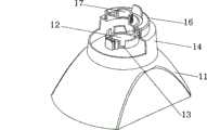
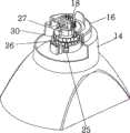
附图3-5示出了根据本发明的车用投影灯一种示例性实施例。该车用投影灯,包括:具有前开口和后开口33的曲面反射体2,所述曲面反射体具有呈曲面结构的内表面以向所述前开口反射光束,并且在所述前开口处安装有凸透镜3;安装部21,所述安装部21在所述后开口33的外围附近从所述曲面反射体2向外(即向与前开口相反的一侧)一体地延伸形成;包括安装座32和安装在所述安装座32上的发光体27的光源,所述发光体27穿过所述安装部21和所述后开口33插入所述曲面反射体2中;以及第一固定装置26,所述第一固定装置26可拆卸地设置在所述安装部21上,用于将所述车用投影灯安装在车辆的灯泡安装结构上。所述安装部21与所述曲面反射体2连接的部位的径向尺寸大于所述安装部2的径向尺寸,特别是大于灯泡安装结构的安装孔12的径向尺寸,以通过所述第一固定装置26将所述车用投影灯安装在车辆的灯泡安装结构上,而不会使曲面反射体2从灯泡安装结构的内部通过安装孔12伸到曲面反射体2之外。 3-5 show an exemplary embodiment of a projection lamp for a vehicle according to the present invention. The projection lamp for a vehicle comprises: a
在一种示例性实施例中,在所述安装部21与所述曲面反射体2连接的部位形成从所述曲面反射体2的外侧凸出的至少一个第一阻挡凸起34。本发明的车用投影灯还包括第二固定装置30,所述第二固定装置30被构造成将所述安装座32可拆卸地保持在所述安装部21内。 In an exemplary embodiment, at least one
在一种实施例中,在透镜体3和曲面反射体2之间设远近光切换装置4,用于根据需要使所述投影灯发射出近射光束和远射光束。安装部21可以是一种筒体结构,但也可以是由多个从曲面反射体2向外一体延伸形成的立柱结构,所述多个立柱布置成圆形。所述筒体的外侧设有外螺纹。与带有螺纹的筒体结构相对应,第一固定装置26为固定环,并且固定环的内侧设有内螺纹,从而使固定环以螺纹连接的方式安装在所述筒体上。 In one embodiment, a far and near
根据本发明的投影灯可进一步包括可在所述筒体(安装部21)上滑动的定位环23。所述定位环23包括位于所述定位环23外侧上的至少一个等间距布置的外定位销25,外定位销可以为2、3或者4个。所述外定位销25的形状和位置与灯泡安装结构上的定位槽13的形状和位置相对应,以使外定位销25可在纵向延伸的定位销13内移动。 The projection lamp according to the present invention may further include a
所述筒体的外壁上设有至少一个沿轴向(纵向)延伸的沟槽22。与沟槽22的形状和位置相对应,所述定位环23的内侧上设有至少一个内定位销24,以便定位环23套接在筒体上时,内定位销24可在沟槽22内移动并防止定位环23相对于筒体转动。 At least one groove 22 extending in the axial direction (longitudinal direction) is provided on the outer wall of the cylinder. Corresponding to the shape and position of the groove 22, at least one inner positioning pin 24 is provided on the inner side of the
作为一种沟槽22和内定位销24配合结构的可替换的实施例,也可在筒体外壁上设有至少一个沿筒体轴向延伸的第一平坦部分35。与第一平坦部分35的形状和位置相对应,在定位环23的内侧上设有至少一个与所述第一平坦部分35相对应的第二平坦部分36,以便定位环23套接在筒体上 时,带有平坦部分35可相对于第二平坦部分36移动并防止定位环23相对于筒体转动。可选地,也可以在车用投影灯中同时设置这种沟槽22和内定位销24配合的结构、以及第一和第二平坦部分配合的结构。 As an alternative embodiment of the matching structure between the groove 22 and the inner positioning pin 24, at least one first flat portion 35 extending in the axial direction of the cylinder can also be provided on the outer wall of the cylinder. Corresponding to the shape and position of the first flat portion 35, at least one second flat portion 36 corresponding to the first flat portion 35 is provided on the inner side of the
在一种示例性实施例中,所述筒体包括从其内壁凸出的阻挡部28。所述光源包括从所述安装座32表面上径向延伸形成的至少一个固定片29。所述固定片29可以是分开设置的,也可以是环绕安装座32的连续的环形结构。第二固定装置30可将所述固定片29保持在所述阻挡部28的与所述曲面反射体2相反的一侧上。进一步地,如图5所示,所述第二固定装置30包括环形结构,所述环形结构包括:与所述筒体的所述外螺纹螺纹连接的内螺纹部分37;以及其内径比所述内螺纹部分的内径较小的保持部分38,即保持部分38相对于内螺纹部分向环形结构的内侧凸出。这样,可通过所述内螺纹部分37将该环形结构螺纹连接到筒体的外螺纹部分上,同时由于保持部分38的内径较小,可使所述保持部分38覆盖住所述筒体的中空部分的一部分,从而使保持部分38将所述固定片29压靠在所述阻挡部28上,进而将光源的安装座32保持在所述筒体内,同时发光体27延伸到所述曲面反射体2内。 In an exemplary embodiment, the barrel includes a stop 28 protruding from its inner wall. The light source includes at least one fixing
可供选择地,可在定位环23和第一固定装置26之间设置缓冲垫圈39,并且在阻挡片29和第二固定装置30之间设置另一缓冲垫圈31。缓冲垫圈31和39的实施例可是弹性橡胶圈。 Alternatively, a
根据本发明的车用投影灯可直接安装在传统的卤素车灯灯泡安装结构内。图6-8示出了根据本发明的车用投影灯安装在车辆的原有灯泡安装结构内的示意图。当安装本发明的车用投影灯时,取下为环形结构的第二固定装置30、光源、第一固定装置26(固定环)以及定位环23,揭开卤素灯的灯泡安装结构的前透明盖板(图中未示出),然后打开卤素灯的外罩14上的端盖16,将投影灯的筒体穿过卤素车前灯的反光罩11的光源安装孔12。由于阻挡凸起34的阻挡作用,使反光罩11的部分不能进一步穿过安装孔12。之后,将定位环23和固定环从卤素车前灯的反光罩11的背面装在筒体上并将定位环23的外定位销25插入卤素车车前灯的反光罩11的定位槽13上,再安装好垫圈39,之后拧紧第一固定装置26(固定环),从而将投影灯的安装部21(筒体)锁紧在卤素车前灯的灯泡安装结构上。 然后,从筒体的后部将光源的发光体27穿过筒体和后开口33插入到曲面反射体2内,再安装垫圈31,之后紧固第二固定装置30。然后,盖上灯罩的前透明盖板,同时在光源的安装座32的后部安装防水密封塞18,再将端盖16安装在外罩14上。最后将来自电源的导线从导线导入口17进入端盖16的内侧,并穿过设置在密封塞18上的多个导线穿孔连接至安装在所述延伸部内的灯泡底座,从而给所述灯泡供电。 The projection lamp for a vehicle according to the present invention can be directly installed in a conventional halogen vehicle light bulb installation structure. 6-8 show schematic diagrams of the vehicle projection lamp installed in the original light bulb installation structure of the vehicle according to the present invention. When the vehicle projection lamp of the present invention is installed, the
根据本发明的投影灯可直接安装在传统卤素车前灯的灯泡安装结构上,不但不会破坏原车前灯的结构,因此安装方便,而且可以较低的价格直接使用配光性好的投影灯。 The projection lamp according to the present invention can be directly installed on the bulb installation structure of the traditional halogen car headlight, not only will not damage the structure of the original car headlight, so it is easy to install, and can directly use the projection lamp with good light distribution at a lower price lamp. the
上面描述了,将根据本发明的车用投影灯安装在原有车前灯的灯泡安装结构上的实施例。但本发明也不局限于此,本领域的技术人员可以理解,也可利用根据本发明的车用投影灯形成一种和原有卤素车前灯的外部结构相同的完整的车前灯,以将这种包括本发明的投影灯的车前灯方便地安装到车辆上,而不必修改车辆本身的其它结构。即这种车前灯包括根据本发明提供的车用投影灯和原有车辆的灯泡安装结构。在另一种实施例中,由于投影灯本身具有可以对光源发出的光束进行发射的曲面反射体,因此可用形状和结构与原有反光罩相同的外罩代替原有车前灯反光罩,即前罩不具有反光性能,这样可降低车前灯的成本。 The above describes the embodiment in which the projection lamp for a vehicle according to the present invention is mounted on the bulb mounting structure of the existing headlight. However, the present invention is not limited thereto. Those skilled in the art can understand that the vehicle projection lamp according to the present invention can also be used to form a complete headlight with the same external structure as the original halogen headlight, so as to Such a headlight including the projection lamp of the present invention can be easily mounted on a vehicle without modifying other structures of the vehicle itself. That is, the vehicle headlight includes the vehicle projection lamp provided by the present invention and the original vehicle bulb installation structure. In another embodiment, since the projection lamp itself has a curved reflector that can emit the light beam emitted by the light source, the original reflector of the headlight can be replaced by an outer cover with the same shape and structure as the original reflector, that is, the front reflector. The cover does not have reflective properties, which can reduce the cost of the headlight. the
尽管对本发明的典型实施例进行了说明,但是显然普通技术人员可以理解,在不背离本发明的精神和原理的情况下可以进行改变,其范围在权利要求书以及其等同物中进行了限定。 While exemplary embodiments of this invention have been described, it will be apparent to those of ordinary skill that changes may be made without departing from the spirit and principles of the invention, the scope of which is defined in the claims and their equivalents. the
Claims (11)
Priority Applications (1)
| Application Number | Priority Date | Filing Date | Title |
|---|---|---|---|
| CN200810028370ACN101585339B (en) | 2008-05-23 | 2008-05-23 | Car projection lamps and headlights |
Applications Claiming Priority (1)
| Application Number | Priority Date | Filing Date | Title |
|---|---|---|---|
| CN200810028370ACN101585339B (en) | 2008-05-23 | 2008-05-23 | Car projection lamps and headlights |
Publications (2)
| Publication Number | Publication Date |
|---|---|
| CN101585339A CN101585339A (en) | 2009-11-25 |
| CN101585339Btrue CN101585339B (en) | 2012-10-10 |
Family
ID=41369833
Family Applications (1)
| Application Number | Title | Priority Date | Filing Date |
|---|---|---|---|
| CN200810028370AExpired - Fee RelatedCN101585339B (en) | 2008-05-23 | 2008-05-23 | Car projection lamps and headlights |
Country Status (1)
| Country | Link |
|---|---|
| CN (1) | CN101585339B (en) |
Citations (5)
| Publication number | Priority date | Publication date | Assignee | Title |
|---|---|---|---|---|
| US4081668A (en)* | 1976-03-26 | 1978-03-28 | Mori Denki Manufacturing Co., Ltd. | Socket-mounting apparatus for lighting devices |
| US5032964A (en)* | 1989-11-13 | 1991-07-16 | Koito Manufacturing Co., Ltd. | Headlight for motor vehicle |
| US20020080607A1 (en)* | 2000-12-27 | 2002-06-27 | Ilyes Laszlo S. | Lamp securing device |
| CN1842442A (en)* | 2003-08-27 | 2006-10-04 | 瓦莱奥·西尔瓦尼亚有限责任公司 | External Search Lens Lights |
| CN201232920Y (en)* | 2008-05-23 | 2009-05-06 | 孙少珍 | Projection lamp for vehicle and headlight |
- 2008
- 2008-05-23CNCN200810028370Apatent/CN101585339B/ennot_activeExpired - Fee Related
Patent Citations (5)
| Publication number | Priority date | Publication date | Assignee | Title |
|---|---|---|---|---|
| US4081668A (en)* | 1976-03-26 | 1978-03-28 | Mori Denki Manufacturing Co., Ltd. | Socket-mounting apparatus for lighting devices |
| US5032964A (en)* | 1989-11-13 | 1991-07-16 | Koito Manufacturing Co., Ltd. | Headlight for motor vehicle |
| US20020080607A1 (en)* | 2000-12-27 | 2002-06-27 | Ilyes Laszlo S. | Lamp securing device |
| CN1842442A (en)* | 2003-08-27 | 2006-10-04 | 瓦莱奥·西尔瓦尼亚有限责任公司 | External Search Lens Lights |
| CN201232920Y (en)* | 2008-05-23 | 2009-05-06 | 孙少珍 | Projection lamp for vehicle and headlight |
Also Published As
| Publication number | Publication date |
|---|---|
| CN101585339A (en) | 2009-11-25 |
Similar Documents
| Publication | Publication Date | Title |
|---|---|---|
| KR101130779B1 (en) | High Power LED Lamp | |
| JP2008171773A (en) | Vehicle lighting apparatus | |
| US9285093B2 (en) | Self-locating light source module | |
| CN204693141U (en) | A kind of LED | |
| CN203907415U (en) | Headlight structure with far and near lamp | |
| CN101585339B (en) | Car projection lamps and headlights | |
| KR100946548B1 (en) | Combination structure of led downlight | |
| CN201232920Y (en) | Projection lamp for vehicle and headlight | |
| CN103148455A (en) | Light distribution device of LED (light emitting diode) light source, automobile headlight provided with light distribution device, and automobile | |
| CN219453812U (en) | Tunnel lamp butt joint structure and tunnel lamp group | |
| CN107388157B (en) | Upper reflective LED high beam spotlight assembly | |
| US10443805B2 (en) | Vehicle lighting fixture | |
| WO2009065285A1 (en) | A projection light for vehicle and a headlight for vehicle | |
| US20060245198A1 (en) | High intensity discharge bulb adapter for vehicles | |
| CN207778191U (en) | Waterproof and shockproof warning lamp convenient to assemble | |
| CN103162181B (en) | LED bulb for horizontal installation and capable of projecting light to ground | |
| CN223388450U (en) | A vehicle-mounted chassis projection atmosphere light | |
| CN216203107U (en) | Bicycle front lamp | |
| CN208475126U (en) | A kind of LED downlight of replaceable lampshade | |
| CN204313169U (en) | Road lamp cap | |
| CN111503537B (en) | Lighting device | |
| CN210511453U (en) | Lamp set | |
| CN204313166U (en) | Road lamp cap | |
| CN207094518U (en) | A kind of upper reflecting LED distance light shot-light assembly | |
| CN110893816A (en) | An agricultural vehicle cab ceiling light |
Legal Events
| Date | Code | Title | Description |
|---|---|---|---|
| C06 | Publication | ||
| PB01 | Publication | ||
| C10 | Entry into substantive examination | ||
| SE01 | Entry into force of request for substantive examination | ||
| C14 | Grant of patent or utility model | ||
| GR01 | Patent grant | ||
| CF01 | Termination of patent right due to non-payment of annual fee | Granted publication date:20121010 Termination date:20150523 | |
| EXPY | Termination of patent right or utility model |