CN101581569B - Calibration Method of Structural Parameters of Binocular Vision Sensing System - Google Patents
Calibration Method of Structural Parameters of Binocular Vision Sensing SystemDownload PDFInfo
- Publication number
- CN101581569B CN101581569BCN2009101468821ACN200910146882ACN101581569BCN 101581569 BCN101581569 BCN 101581569BCN 2009101468821 ACN2009101468821 ACN 2009101468821ACN 200910146882 ACN200910146882 ACN 200910146882ACN 101581569 BCN101581569 BCN 101581569B
- Authority
- CN
- China
- Prior art keywords
- camera
- calibration
- image
- pole
- coordinate system
- Prior art date
- Legal status (The legal status is an assumption and is not a legal conclusion. Google has not performed a legal analysis and makes no representation as to the accuracy of the status listed.)
- Expired - Fee Related
Links
Images


Landscapes
- Length Measuring Devices By Optical Means (AREA)
Abstract
Description
Translated fromChinese技术领域technical field
本发明涉及一种双目视觉传感系统的标定方法,属于视觉测量领域,特别适用于两个相机的光轴成夹角分布的双目传感系统的标定。The invention relates to a calibration method of a binocular vision sensing system, which belongs to the field of visual measurement, and is particularly suitable for the calibration of a binocular sensing system in which the optical axes of two cameras are distributed at an angle.
背景技术Background technique
视觉测量具有非接触、测速快、方便灵活等优点,在虚拟现实、工业检测等领域有着重要的意义和广阔的应用前景。在双目视觉传感系统中,标定视觉传感器的结构参数,即两个相机之间的位置关系,是视觉传感器进行三维测量的必要前提。Visual measurement has the advantages of non-contact, fast measurement speed, convenience and flexibility, etc. It has important significance and broad application prospects in the fields of virtual reality and industrial inspection. In the binocular vision sensor system, the calibration of the structural parameters of the vision sensor, that is, the positional relationship between the two cameras, is a necessary prerequisite for the three-dimensional measurement of the vision sensor.
从双目视觉模型可知,双目视觉传感系统的标定是指相机的内部参数的标定和双目视觉传感系统的结构参数(外部参数)的标定。传统的双目视觉传感器结构参数的标定方法分为两大类,一类标定方法是内外参数一起标定,并且进行射影重建,这类标定方法可以用在计算机虚拟现实中,但是不适用于测量。另一类标定方法就是内外参数分开标定的欧式三维重建,这一类标定方法才能应用于测量。对于外部参数的标定目前有一种方法就是通过线性方程直接求解左右相机之间的旋转矩阵和平移矩阵,另一种方法就是利用基础矩阵来求解左右相机的旋转矩阵和平移矩阵,但是这两种方法都是基于代数方法,避免不了解线性方程带来的大量计算和引入的误差。It can be seen from the binocular vision model that the calibration of the binocular vision sensing system refers to the calibration of the internal parameters of the camera and the calibration of the structural parameters (external parameters) of the binocular vision sensing system. The traditional calibration methods of structural parameters of binocular vision sensors are divided into two categories. One kind of calibration method is to calibrate the internal and external parameters together and perform projective reconstruction. This kind of calibration method can be used in computer virtual reality, but it is not suitable for measurement. Another type of calibration method is the European 3D reconstruction in which internal and external parameters are calibrated separately, and this type of calibration method can only be applied to measurement. For the calibration of external parameters, there is currently a method to directly solve the rotation matrix and translation matrix between the left and right cameras through linear equations. Another method is to use the fundamental matrix to solve the rotation matrix and translation matrix of the left and right cameras, but these two methods All are based on algebraic methods, avoiding a large number of calculations and errors caused by not understanding linear equations.
发明内容Contents of the invention
本发明的目的在于提供一种双目视觉传感器结构参数的标定方法,具有计算简单、精度较高的优点。The purpose of the present invention is to provide a method for calibrating structural parameters of a binocular vision sensor, which has the advantages of simple calculation and high precision.
根据本发明的一方面,提供一种双目视觉传感器结构参数的标定方法,该方法包括:利用左相机光心Ol、右相机光心Or、左相机的左图像面、右相机的右图像面以及被测物体上任一点P建立对极几何关系;利用对极几何关系得出包含相机内部参数和系统结构参数的基础矩阵;通过分解基础矩阵分别得到左右相机的左右极点el和er;利用左右极点信息分别计算左右旋转矩阵Rl和Rr,左右相机分别以各自的光心Ol和Or、分别以左右旋转矩阵Rl和Rr进行相机旋转校正,使得左右相机的光轴平行,同时分别以左右旋转矩阵Rl和Rr旋转左相机的左图像面和右相机的右图像面,使左右图像面上的极线相互平行,由此使得空间物点在左右图像面上的坐标只有在x轴不同,在y轴和z轴相同;在经过旋转校正后的坐标系下根据标定板反求出左相机光心Ol和右相机光心Or之间的连线的长度,由此完成所述标定,其中,左右相机对所述标定板同时进行拍摄。According to one aspect of the present invention, a method for calibrating structural parameters of a binocular vision sensor is provided, the method comprising: using the optical center Ol of the left camera, the optical center Or of the right camera, the left image plane of the left camera, the right Establish the epipolar geometric relationship at any point P on the image surface and the measured object; use the antipolar geometric relationship to obtain the fundamental matrix including the internal parameters of the camera and system structure parameters; obtain the left and right extreme points el and er of the left and right cameras by decomposing the fundamental matrix ; Use the left and right pole information to calculate the left and right rotation matrices Rl and Rr respectively, and the left and right cameras use their respective optical centers Ol and Or to perform camera rotation correction with the left and right rotation matrices Rl and Rr respectively, so that the light of the left and right cameras At the same time, the left image plane of the left camera and the right image plane of the right camera are rotated by the left and right rotation matrices Rl and Rr respectively, so that the epipolar lines on the left and right image planes are parallel to each other, thus making the spatial object point on the left and right image planes The coordinates above are only different on the x-axis, and are the same on the y-axis and the z-axis; in the coordinate system after rotation correction, according to the calibration plate, find the connection line between the left camera optical center Ol and the right camera optical center Or length, thereby completing the calibration, wherein the left and right cameras simultaneously photograph the calibration plate.
根据本发明的标定方法简单、快速,不需要复杂的计算和昂贵的标定辅助设备,可用于双目视觉传感系统的标定。The calibration method according to the invention is simple and fast, does not require complex calculations and expensive calibration auxiliary equipment, and can be used for calibration of binocular vision sensing systems.
附图说明Description of drawings
通过结合附图,从下面的实施例的描述中,本发明这些和/或其它方面及优点将会变得清楚,并且更易于理解,其中:These and/or other aspects and advantages of the present invention will become clear and easier to understand from the description of the following embodiments in conjunction with the accompanying drawings, wherein:
图1示出了根据本发明的双目立体视觉和极线约束的示意图;Fig. 1 shows a schematic diagram of binocular stereo vision and epipolar constraints according to the present invention;
图2示出了根据本发明的共面约束的示意图;Fig. 2 shows a schematic diagram of coplanar constraints according to the present invention;
图3示出了根据本发明的光轴相互平行的双目立体几何的示意图;Fig. 3 shows a schematic diagram of binocular stereo geometry with optical axes parallel to each other according to the present invention;
图4示出了根据本发明的由左相机拍摄的标定板左图像的示意图;Fig. 4 shows the schematic diagram of the left image of the calibration plate taken by the left camera according to the present invention;
图5示出了根据本发明的由右相机拍摄的标定板右图像的示意图;Fig. 5 shows a schematic diagram of the right image of the calibration plate taken by the right camera according to the present invention;
图6示出了根据本发明的双目视觉传感器结构参数的标定方法的流程图。Fig. 6 shows a flow chart of a method for calibrating structural parameters of a binocular vision sensor according to the present invention.
具体实施方式Detailed ways
现在将详细描述本发明的实施例,其示例在附图中示出,其中,相同的标号始终表示相同的部件。下面通过参照附图来描述实施例以解释本发明。Reference will now be made in detail to embodiments of the invention, examples of which are illustrated in the accompanying drawings, wherein like reference numerals refer to like parts throughout. The embodiments are described below in order to explain the present invention by referring to the figures.
针对现有技术存在的问题,本发明引入了对极几何和基础矩阵的概念,但是仅仅利用双目相机之间的空间几何关系对双目视觉传感系统结构参数进行标定,这样避免了求解线性方程带来的大量计算和引入的误差。Aiming at the problems existing in the prior art, the present invention introduces the concepts of epipolar geometry and fundamental matrix, but only uses the spatial geometric relationship between the binocular cameras to calibrate the structural parameters of the binocular vision sensing system, thus avoiding the need to solve linear A large number of calculations and errors introduced by the equation.
本发明引入一种新的标定方法。该方法是在相机内部参数(包括畸变系数)已经知道的基础上,利用对极几何理论得出包含相机内部参数和系统结构参数的基础矩阵,通过分解基础矩阵可以得到双目相机的左右极点,利用左右极点信息计算左右旋转矩阵,以左右旋转矩阵旋转左右相机使光轴平行,同时以左右旋转矩阵旋转左右图像面使相应图像面上的极线相互平行、空间物点在左右图像面上的坐标只有x轴不同,y轴和z轴是相同的,然后利用三角关系就可以进行空间物点信息的三维重建。The present invention introduces a new calibration method. This method is based on the known internal parameters of the camera (including the distortion coefficient), and uses the theory of epipolar geometry to obtain the fundamental matrix including the internal parameters of the camera and system structure parameters. By decomposing the fundamental matrix, the left and right poles of the binocular camera can be obtained. Use the left and right pole information to calculate the left and right rotation matrix, rotate the left and right cameras with the left and right rotation matrix to make the optical axes parallel, and at the same time use the left and right rotation matrix to rotate the left and right image planes so that the polar lines on the corresponding image planes are parallel to each other, and the spatial object points are on the left and right image planes The coordinates are only different in the x-axis, and the y-axis and the z-axis are the same, and then the three-dimensional reconstruction of the spatial object point information can be carried out by using the triangular relationship.
下面参照图1至图3从理论上对双目视觉传感系统结构参数的标定方法进行详细说明,所述双目视觉传感系统包括左相机和右相机。The method for calibrating the structural parameters of the binocular vision sensing system will be theoretically described in detail below with reference to FIGS. 1 to 3 . The binocular vision sensing system includes a left camera and a right camera.
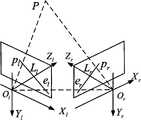
图1示出了根据本发明的双目立体视觉和极线约束的示意图。Fig. 1 shows a schematic diagram of binocular stereo vision and epipolar constraints according to the present invention.
如图1所示:Ol是左相机光心,Or是右相机光心,P是被测物体上任一点。由Ol、Or和P构成的平面称为极平面,左相机的左图像面和极平面的交线称为左极线Ll,右相机的右图像面和极平面的交线称为右极线Lr,Ol和Or之间的连线称为基线,基线和左图像面的交点称为左极点el,基线和右图像面的交点称为右极点er。这种由左右图像面和极平面构成的描述相机之间存在关系的几何就是对极几何,它与场景结构无关,只依赖于相机的内外参数。本发明的标定方法就是基于这种关系建立起来的。As shown in Figure 1: Ol is the optical center of the left camera, Or is the optical center of the right camera, and P is any point on the measured object. The plane composed of Ol , Or and P is called the polar plane, the intersection line between the left image plane of the left camera and the polar plane is called the left polar line Ll , and the intersection line between the right image plane of the right camera and the polar plane is called The right polar line Lr , the connecting line between Ol and Or is called the baseline, the intersection point of the baseline and the left image plane is called the left pole el , and the intersection point of the baseline and the right image plane is called the right pole er . The geometry that describes the relationship between the cameras, which is composed of the left and right image planes and the polar plane, is the epipolar geometry, which has nothing to do with the scene structure and only depends on the internal and external parameters of the camera. The calibration method of the present invention is established based on this relationship.
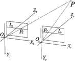
图2示出了根据本发明的共面约束的示意图。Fig. 2 shows a schematic diagram of coplanar constraints according to the present invention.
如图2所示,T=Ol-Or是左右两个相机的平移矩阵,Pl、Pr是所述点P在左、右相机坐标系中左右图像面上的物理坐标系,在射影空间它们分别代表左右图像面上的齐次坐标系,在欧式空间它们分别是两个向量。Ol Or P决定了一个平面,由共面关系可知:As shown in Figure 2, T=Ol -O r is the translation matrix of the left and right cameras, Pl and Pr are the physical coordinate systems of the point P on the left and right camera coordinate systems on the left and right image planes, in In the projective space, they respectively represent the homogeneous coordinate system on the left and right image planes, and in the Euclidean space, they are two vectors respectively. Ol Or P determines a plane, which can be known from the coplanar relationship:
(Pl-T)T(T×Pl)=0(Pl -T)T (T×Pl )=0
其中,Pr=R(Pl-T),R是左相机到右相机的旋转矩阵。Wherein, Pr =R(Pl -T), R is the rotation matrix from the left camera to the right camera.
由以上两个公式可得出:It can be obtained from the above two formulas:
PrTRSPl=0 (1)PrT RSPl =0 (1)
其中:
令E=RS,则E为本质矩阵,本质矩阵只与视觉传感系统的外部参数有关,秩为2,自由度为5。Let E=RS, then E is the essential matrix, the essential matrix is only related to the external parameters of the visual sensing system, the rank is 2, and the degree of freedom is 5.
设pl和pr是点P在左右相机图像面上的像素点坐标,Kl和Kr是左右图像的内部参数矩阵,则可得出:pl=KlPl和pr=KrPr,变换后得:Let pl and pr be the pixel point coordinates of point P on the left and right camera image planes, Kl and Kr are the internal parameter matrices of the left and right images, then it can be drawn: pl = Kl Pl and pr = Kr Pr , after transformation:
Pl=Kl-1pl,Pr=Kr-1prPl =Kl-1 pl , Pr =Kr-1 pr
将上两式带入公式(1),得出:prTKr-TEKl-1pl=0。Putting the above two formulas into formula (1), it can be obtained: prT Kr-T EKl-1 pl =0.
令F=Kr-TEKl-1,得出:Let F=Kr-T EKl-1 , get:
prTFpl=0 (2)prT Fpl =0 (2)
公式(2)中的F就是基础矩阵,它的秩为2,自由度为7,与视觉传感系统的内外参数都有关系。F in formula (2) is the fundamental matrix, its rank is 2, and its degree of freedom is 7, which is related to the internal and external parameters of the visual sensing system.
根据基础矩阵可以计算左右极线和极点。具体地讲,根据射影几何的知识,点在一条直线上,则:prTLr=0,再结合公式(2)就可以得到右极线为:The left and right epipolar lines and poles can be calculated from the fundamental matrix. Specifically, according to the knowledge of projective geometry, if the points are on a straight line, then: prT Lr =0, combined with formula (2), the right polar line can be obtained as:
Lr=FplLr = Fpl
同理,可得到左极线为:Ll=FTprSimilarly, the left polar line can be obtained as: Ll = FT pr
由于右极点在所有的右极线上:erTLr=erTFpl=0,可以得到:Since the right pole is on all right polar lines: erT Lr =erT Fpl =0, we can get:
FTer=0FT er =0
同理,可得出:Fel=0Similarly, it can be drawn that: Fel = 0
将F和FT进行齐次方程的奇异值分解,就可以解出左右极点。The left and right poles can be solved by performing the singular value decomposition of the homogeneous equation on F andFT .
得到左右极点的信息以后就可以求解出两个旋转矩阵Rl和Rr,左右相机分别以各自的光心、分别以左右旋转矩阵Rl和Rr进行相机旋转校正,旋转以后左右相机的方位相同,只有原点不重合,在左右相机中的左右图像面也以各自的旋转矩阵进行空间坐标变换。结果,空间点在左右相机中的坐标只有在x轴是不同的,在y和z轴是相同的,这样达到理想状态以后重建就变得非常简单。可求出下面的左右旋转矩阵Rl和Rr。After obtaining the information of the left and right poles, two rotation matrices Rl and Rr can be solved. The left and right cameras use their respective optical centers to perform camera rotation correction with the left and right rotation matrices Rl and Rr respectively. After rotation, the orientation of the left and right cameras In the same way, only the origins do not coincide, and the left and right image planes in the left and right cameras also perform space coordinate transformation with their respective rotation matrices. As a result, the coordinates of the spatial point in the left and right cameras are only different in the x-axis, and are the same in the y and z-axis, so that the reconstruction after reaching the ideal state becomes very simple. The following left and right rotation matrices Rl and Rr can be obtained.
建立一个以Ol为原心的坐标系统(el1,el2,el3),其中,左旋转矩阵
el3=el1×el2el3 =el1 ×el2
其中,elx、ely、elz是左极点el在未旋转的左相机坐标系下的坐标,z=(0 0 1)T是在所述左相机坐标系中任取的一个向量。Among them, elx , ely , and elz are the coordinates of the left pole el in the unrotated left camera coordinate system, and z=(0 0 1)T is a vector randomly selected in the left camera coordinate system.
er3=er1×er2er3 =er1 ×er2
其中,erx、ery、erz是右极点er在未旋转的右相机坐标系下的坐标,z′=(a b c)T是z点对应的右极线Lz=Fz上的任一点。Among them, erx , ery , erz are the coordinates of the right pole er in the unrotated right camera coordinate system, z′=(a b c)T is any point on the right polar line Lz =Fz corresponding to point z .
这样,就保证了相机旋转以后的共面性。经过以上两个矩阵的旋转,左右相机就旋转到了理想的状态。In this way, the coplanarity after the camera is rotated is guaranteed. After the rotation of the above two matrices, the left and right cameras are rotated to the ideal state.
此外,左右图像面的旋转是在归一化为物理坐标系下进行的,左右图像面上携带标定板空间信息的像素坐标是通过像素坐标系和物理坐标系之间的关系转化为归一化物理坐标系进行旋转的,这样旋转的图像面已经消除了左右相机内部参数的差异。在旋转以后再将左右相机乘以相同的理想内部参数,恢复图像面的像素坐标系。这样成像面已经被理想化,带来的好处就是空间点在左右图像面上所在的左右极线y轴的坐标相同。In addition, the rotation of the left and right image surfaces is normalized to the physical coordinate system, and the pixel coordinates carrying the spatial information of the calibration plate on the left and right image surfaces are transformed into a normalized coordinate system through the relationship between the pixel coordinate system and the physical coordinate system. The physical coordinate system is rotated, so that the rotated image plane has eliminated the difference in the internal parameters of the left and right cameras. After the rotation, the left and right cameras are multiplied by the same ideal internal parameters to restore the pixel coordinate system of the image plane. In this way, the imaging surface has been idealized, and the benefit is that the coordinates of the left and right epipolar lines where the spatial point is located on the left and right image surfaces are the same.
这样,左右相机被理想化为内部参数相同、x轴重合、y和z轴分别平行的理想状态,如图3所示。In this way, the left and right cameras are idealized as an ideal state with the same internal parameters, coincident x-axis, and parallel y-axis and z-axis, as shown in FIG. 3 .
图3示出了根据本发明的光轴相互平行的双目立体几何的示意图。Fig. 3 shows a schematic diagram of binocular stereo geometry with optical axes parallel to each other according to the present invention.
设空间点P在Ol下的坐标系为(x,y,z),在Or下的坐标系为(x-b,y,z),其中b为基线距离,
根据以上公式可以得到空间点P的三维坐标如下:According to the above formula, the three-dimensional coordinates of the spatial point P can be obtained as follows:
其中,x、y和z是物理坐标系,以mm为单位,ul和vl是左图像面上物体所成像的像素坐标,ur和vr是右图像面上物体所成像的像素坐标;K为内部参数,αx=f/dx,αy=f/dy,其中,f为相机的焦距,dx和dy分别为CCD的像素单位,即,一个像素的横向大小和纵向大小;(u0,v0)为主点(光轴和图像面的交点)在像素坐标系中的位置,内部参数以像素为单位。Among them, x, y and z are the physical coordinate system, in mm, ul and vl are the pixel coordinates of the object imaged on the left image plane, ur and vr are the pixel coordinates of the object imaged on the right image plane ; K is an internal parameter, αx =f/dx , αy =f/dy , wherein, f is the focal length of the camera, dx and dy are the pixel units of the CCD respectively, that is, the lateral size and Vertical size; (u0 , v0 ) is the position of the principal point (the intersection of the optical axis and the image plane) in the pixel coordinate system, and the internal parameters are in pixels.
从上述的推导可以看出,经过图像旋转校正的三维重建已经变得简单,计算量也大大降低。但是如果不求基线长度,则从公式(4)可以看出,求出来的物体三维坐标是相对的,所以在图像旋转校正之后再在经过旋转校正后的坐标系下根据标定板反求出基线的长度,这样就完成了标定。From the above derivation, it can be seen that the 3D reconstruction after image rotation correction has become simple and the amount of calculation is greatly reduced. However, if the baseline length is not calculated, it can be seen from the formula (4) that the three-dimensional coordinates of the obtained object are relative, so after the image rotation correction, the baseline is calculated inversely according to the calibration plate in the coordinate system after the rotation correction length, the calibration is completed.
下面描述根据标定板反求出基线的长度的示例性步骤。Exemplary steps for deriving the length of the baseline from the calibration plate are described below.
标定板是一块尺寸具有很高精度的棋盘格,在该棋盘格的横排和竖排上分别布置有彼此黑白相间的方格。标定的整个过程可利用左右相机同时对标定板摄像,然后利用标定板的角点信息(棋盘格黑白相间的地方)来完成双目视觉传感系统标定(包括求解基础矩阵、基线长度等)。因此,利用标定板反求基线长度的步骤可包括:利用标定板的任意两个不同角点在左右相机同时拍摄的标定板左右图像中的像素坐标(在标定过程中左右相机可在不同角度同时拍摄多组标定板左右图像),再利用前面提到的旋转校正后的坐标系下的三维重建来求出所述任意两个不同角点的三维坐标,此时求出的三维信息是相对的,即它们的长、宽、高都是与基线长度成正比的;然后求出上述任意两个不同角点之间的距离(因为知道三维坐标后可方便求出该距离),此时求出的两个不同角点距离也是与基线长度成正比的一个相对距离,因为高精度的棋盘格两个不同角点之间的实际距离是可以得到的,所以利用上述两个距离相等就可反求出唯一的未知数,即,基线的长度。图4示出了根据本发明的由左相机拍摄的标定板左图像的示意图,图5示出了根据本发明的由右相机拍摄的标定板右图像的示意图,左右相机同时拍摄标定板左右图像。The calibration board is a checkerboard with very high precision in size, and black and white squares are arranged on the horizontal and vertical rows of the checkerboard. The whole process of calibration can use the left and right cameras to take pictures of the calibration board at the same time, and then use the corner information of the calibration board (the place where the checkerboard is black and white) to complete the calibration of the binocular vision sensor system (including solving the basic matrix, baseline length, etc.). Therefore, the step of using the calibration board to invert the length of the baseline may include: using any two different corner points of the calibration board to capture the pixel coordinates of the left and right images of the calibration board simultaneously captured by the left and right cameras (the left and right cameras can simultaneously capture the left and right images at different angles during the calibration process) Take multiple groups of calibration plate left and right images), and then use the aforementioned three-dimensional reconstruction under the coordinate system after rotation correction to obtain the three-dimensional coordinates of any two different corner points. The three-dimensional information obtained at this time is relative , that is, their length, width, and height are all proportional to the length of the baseline; then find the distance between any two different corner points above (because the distance can be easily found after knowing the three-dimensional coordinates), and then find The distance between two different corner points of is also a relative distance proportional to the length of the baseline, because the actual distance between two different corner points of the high-precision checkerboard can be obtained, so the above two distances can be used to inversely calculate out the only unknown, namely, the length of the baseline. Fig. 4 shows the schematic diagram of the left image of the calibration board taken by the left camera according to the present invention, and Fig. 5 shows the schematic diagram of the right image of the calibration board taken by the right camera according to the present invention, and the left and right cameras shoot the left and right images of the calibration board simultaneously .
图6示出了根据本发明的双目视觉传感器结构参数的标定方法的流程图。Fig. 6 shows a flow chart of a method for calibrating structural parameters of a binocular vision sensor according to the present invention.
参照图6,在步骤601,利用左相机光心Ol、右相机光心Or、左相机的左图像面、右相机的右图像面以及被测物体上任一点P建立对极几何关系。Referring to FIG. 6 , in
在步骤602,利用对极几何关系得出包含相机内部参数和系统结构参数的基础矩阵。In
在步骤603,通过分解基础矩阵分别得到左右相机的左右极点el和er。In
在步骤604,利用左右极点信息分别计算左右旋转矩阵Rl和Rr,左右相机分别以各自的光心Ol和Or、分别以左右旋转矩阵Rl和Rr进行相机旋转校正,使得左右相机的光轴平行,同时分别以左右旋转矩阵Rl和Rr旋转左相机的左图像面和右相机的右图像面,使左右图像面上的极线相互平行,由此使得空间物点在左右图像面上的坐标只有在x轴不同,在y轴和z轴相同。In
在步骤605,在理想坐标系下根据标定板反求出左相机光心Ol和右相机光心Or之间的连线的距离,由此完成所述标定。In
因此,根据本发明的标定方法只需要相机参数以及标定相机参数时用到的平面靶标图片角点坐标信息。利用对极几何计算包含双目相机位置关系的基础矩阵,通过分解基础矩阵得到左右图像面上的极点。然后利用左右极点信息分别计算左右旋转矩阵,使左右相机方位相同的,图像面上的极点位于无穷远处,极线相互平行。此后,可利用三角关系进行三维重建。根据本发明的结构参数的标定方法简单、快速,不需要复杂的计算和昂贵的标定辅助设备,可用于双目视觉传感系统的标定。Therefore, the calibration method according to the present invention only needs the camera parameters and the corner point coordinate information of the plane target picture used when calibrating the camera parameters. Using epipolar geometry to calculate the fundamental matrix containing the positional relationship of binocular cameras, the poles on the left and right image planes are obtained by decomposing the fundamental matrix. Then use the left and right pole information to calculate the left and right rotation matrices, so that the left and right cameras have the same orientation, the poles on the image plane are located at infinity, and the epipolar lines are parallel to each other. Thereafter, the triangular relationship can be used for 3D reconstruction. The method for calibrating structural parameters according to the invention is simple and fast, does not require complex calculations and expensive calibration auxiliary equipment, and can be used for calibrating binocular vision sensing systems.
虽然已经参照本发明的示例性实施例具体描述和显示了本发明,但是本领域的普通技术人员应该理解,在不脱离由权利要求限定的本发明的精神和范围的情况下,可以对其进行形式和细节的各种改变。While the invention has been specifically described and shown with reference to exemplary embodiments of the invention, it will be understood by those skilled in the art that modifications may be made thereto without departing from the spirit and scope of the invention as defined by the claims. Various changes in form and detail.
Claims (3)
Translated fromChinese

Priority Applications (1)
| Application Number | Priority Date | Filing Date | Title |
|---|---|---|---|
| CN2009101468821ACN101581569B (en) | 2009-06-17 | 2009-06-17 | Calibration Method of Structural Parameters of Binocular Vision Sensing System |
Applications Claiming Priority (1)
| Application Number | Priority Date | Filing Date | Title |
|---|---|---|---|
| CN2009101468821ACN101581569B (en) | 2009-06-17 | 2009-06-17 | Calibration Method of Structural Parameters of Binocular Vision Sensing System |
Publications (2)
| Publication Number | Publication Date |
|---|---|
| CN101581569A CN101581569A (en) | 2009-11-18 |
| CN101581569Btrue CN101581569B (en) | 2011-01-12 |
Family
ID=41363824
Family Applications (1)
| Application Number | Title | Priority Date | Filing Date |
|---|---|---|---|
| CN2009101468821AExpired - Fee RelatedCN101581569B (en) | 2009-06-17 | 2009-06-17 | Calibration Method of Structural Parameters of Binocular Vision Sensing System |
Country Status (1)
| Country | Link |
|---|---|
| CN (1) | CN101581569B (en) |
Families Citing this family (43)
| Publication number | Priority date | Publication date | Assignee | Title |
|---|---|---|---|---|
| CN101876532B (en)* | 2010-05-25 | 2012-05-23 | 大连理工大学 | Camera on-field calibration method in measuring system |
| CN102679896A (en)* | 2011-07-15 | 2012-09-19 | 上海工程技术大学 | Track gauge measuring method based on machine vision |
| GB201114406D0 (en)* | 2011-08-22 | 2011-10-05 | Isis Innovation | Remote monitoring of vital signs |
| CN102506757B (en)* | 2011-10-10 | 2014-04-23 | 南京航空航天大学 | Self-positioning method in multi-angle measurement of binocular stereo measurement system |
| CN102749061B (en)* | 2012-07-26 | 2014-12-24 | 上海工程技术大学 | Steel rail abrasion measuring method based on dynamic template |
| CN102809476B (en)* | 2012-08-22 | 2014-10-22 | 北京理工大学 | Method for calibrating axis error of two photoelectronic imaging systems fixed coaxially back to back |
| CN102901490B (en)* | 2012-09-04 | 2014-08-06 | 北京信息科技大学 | Image matching method based on dynamic threshold, and system |
| CN103148802B (en)* | 2013-01-16 | 2015-03-11 | 吉林大学 | Overhead size binocular panoramic visual inspection system for commercial automobile |
| CN103077524A (en)* | 2013-01-25 | 2013-05-01 | 福州大学 | Calibrating method of hybrid vision system |
| CN104173054B (en)* | 2013-05-21 | 2017-04-12 | 杭州海康威视数字技术股份有限公司 | Measuring method and measuring device for height of human body based on binocular vision technique |
| US9628778B2 (en)* | 2013-10-14 | 2017-04-18 | Eys3D Microelectronics, Co. | Calibration system of a stereo camera and calibration method of a stereo camera |
| TWI549479B (en)* | 2013-10-14 | 2016-09-11 | 鈺立微電子股份有限公司 | Calibration system of a stereo camera and calibration method of a stereo camera |
| CN103983186B (en)* | 2014-04-17 | 2016-08-24 | 内蒙古大学 | Binocular vision system bearing calibration and calibration equipment |
| CN104036542B (en)* | 2014-05-21 | 2017-01-25 | 北京信息科技大学 | Spatial light clustering-based image surface feature point matching method |
| CN104019799B (en)* | 2014-05-23 | 2016-01-13 | 北京信息科技大学 | A Relative Orientation Method for Computing Fundamental Matrix Using Local Parameter Optimization |
| CN104240289B (en)* | 2014-07-16 | 2017-05-03 | 崔岩 | Three-dimensional digitalization reconstruction method and system based on single camera |
| CN104167001B (en)* | 2014-08-27 | 2017-02-15 | 大连理工大学 | Large-visual-field camera calibration method based on orthogonal compensation |
| CN104316335B (en)* | 2014-11-19 | 2017-01-18 | 烟台开发区海德科技有限公司 | 3D automobile wheel positioner multi-camera calibration system and method |
| CN104807405B (en)* | 2015-04-27 | 2017-05-10 | 四川大学 | A 3D Coordinate Measurement Method Based on Ray Angle Calibration |
| CN105187812B (en)* | 2015-09-02 | 2016-11-30 | 中国兵器工业计算机应用技术研究所 | A kind of binocular vision solid matching method |
| JP6659317B2 (en)* | 2015-11-17 | 2020-03-04 | 株式会社東芝 | Position and orientation estimation device, position and orientation estimation program, and vacuum cleaner system |
| CN105931261B (en)* | 2016-07-08 | 2018-11-27 | 北京格灵深瞳信息技术有限公司 | A kind of binocular solid Camera extrinsic number modification method and device |
| CN106844823B (en)* | 2016-11-23 | 2020-08-28 | 广州广日电梯工业有限公司 | Modeling method for staircase civil engineering |
| CN106600653B (en)* | 2016-12-30 | 2020-05-19 | 亿嘉和科技股份有限公司 | Zoom camera optical center calibration method |
| CN106713897B (en)* | 2017-02-27 | 2018-03-09 | 驭势(上海)汽车科技有限公司 | Binocular camera and the method for self-calibrating for binocular camera |
| CN106981083B (en)* | 2017-03-22 | 2019-06-28 | 大连理工大学 | The substep scaling method of Binocular Stereo Vision System camera parameters |
| CN112288826B (en)* | 2017-03-23 | 2022-05-31 | 展讯通信(上海)有限公司 | Calibration method and device of binocular camera and terminal |
| CN109211102B (en)* | 2017-07-03 | 2020-10-27 | 北京信息科技大学 | Subpixel-level corner detection method and system |
| CN109958311A (en)* | 2017-12-25 | 2019-07-02 | 大连楼兰科技股份有限公司 | Vehicle azimuth angle detection system applied to parking lot |
| CN109961476A (en)* | 2017-12-25 | 2019-07-02 | 大连楼兰科技股份有限公司 | Underground parking lot positioning method based on vision |
| CN109084959B (en)* | 2018-06-05 | 2020-10-02 | 南京理工大学 | An Optical Axis Parallelism Correction Method Based on Binocular Ranging Algorithm |
| CN109900301B (en)* | 2019-04-02 | 2022-10-25 | 哈尔滨工程大学 | Binocular stereo positioning angle compensation method in dynamic environment |
| CN110099220B (en)* | 2019-06-17 | 2021-04-13 | 广东中星微电子有限公司 | Panoramic stitching method and device |
| CN110332930B (en)* | 2019-07-31 | 2021-09-17 | 小狗电器互联网科技(北京)股份有限公司 | Position determination method, device and equipment |
| CN111080714B (en)* | 2019-12-13 | 2023-05-16 | 太原理工大学 | A Calibration Method of Parallel Binocular Camera Based on 3D Reconstruction |
| CN111145271B (en)* | 2019-12-30 | 2023-04-28 | 广东博智林机器人有限公司 | Method and device for determining accuracy of camera parameters, storage medium and terminal |
| CN112051160B (en)* | 2020-09-09 | 2022-04-19 | 中山大学 | Method, system, equipment and storage medium for measuring bending stiffness of segment joints |
| CN112408281B (en)* | 2020-09-28 | 2022-10-14 | 亿嘉和科技股份有限公司 | Bucket adjusting operation guiding method of bucket arm vehicle based on visual tracking |
| CN112493228B (en)* | 2020-10-28 | 2021-12-14 | 河海大学 | Laser bird repelling method and system based on three-dimensional information estimation |
| CN113223182B (en)* | 2021-04-28 | 2024-05-14 | 深圳市思麦云科技有限公司 | Learning terminal applied to automobile industry based on MR (magnetic resonance) glasses technology |
| CN114067002B (en)* | 2022-01-17 | 2023-02-17 | 江苏中云筑智慧运维研究院有限公司 | Binocular camera external parameter determination method and system |
| CN114998532B (en)* | 2022-08-05 | 2022-11-01 | 中通服建设有限公司 | Three-dimensional image visual transmission optimization method based on digital image reconstruction |
| CN118714277B (en)* | 2024-08-29 | 2024-12-31 | 深圳视点创新科技有限公司 | 3D (three-dimensional) calibration effect evaluation method of 3D camera and computer storage medium |
Citations (3)
| Publication number | Priority date | Publication date | Assignee | Title |
|---|---|---|---|---|
| CN1971206A (en)* | 2006-12-20 | 2007-05-30 | 北京航空航天大学 | Calibration method for binocular vision sensor based on one-dimension target |
| CN101308012A (en)* | 2008-05-29 | 2008-11-19 | 上海交通大学 | Calibration method of dual-monocular white light three-dimensional measurement system |
| CN101320474A (en)* | 2008-06-25 | 2008-12-10 | 浙江工业大学 | A Self-Calibration Method of Extrinsic Camera Parameters for Rotating Stereo Vision |
- 2009
- 2009-06-17CNCN2009101468821Apatent/CN101581569B/ennot_activeExpired - Fee Related
Patent Citations (3)
| Publication number | Priority date | Publication date | Assignee | Title |
|---|---|---|---|---|
| CN1971206A (en)* | 2006-12-20 | 2007-05-30 | 北京航空航天大学 | Calibration method for binocular vision sensor based on one-dimension target |
| CN101308012A (en)* | 2008-05-29 | 2008-11-19 | 上海交通大学 | Calibration method of dual-monocular white light three-dimensional measurement system |
| CN101320474A (en)* | 2008-06-25 | 2008-12-10 | 浙江工业大学 | A Self-Calibration Method of Extrinsic Camera Parameters for Rotating Stereo Vision |
Non-Patent Citations (3)
| Title |
|---|
| JP特开平11-53549A 1999.02.26 |
| 王荣本等."双目视觉在目标测量中的应用".《公路交通科技》.2007,第24卷(第2期),全文. |
| 王锋等."基于双目视觉跟踪的三维拼接技术".《北京机械工业学院学报》.2008,第23卷(第4期),全文. |
Also Published As
| Publication number | Publication date |
|---|---|
| CN101581569A (en) | 2009-11-18 |
Similar Documents
| Publication | Publication Date | Title |
|---|---|---|
| CN101581569B (en) | Calibration Method of Structural Parameters of Binocular Vision Sensing System | |
| CN103278138B (en) | Method for measuring three-dimensional position and posture of thin component with complex structure | |
| CN114705122B (en) | Large-view-field stereoscopic vision calibration method | |
| CN100417231C (en) | Stereo vision hardware-in-the-loop simulation system and method | |
| CN116051659B (en) | A joint calibration method of line scan camera and 2D laser scanner | |
| CN106056620B (en) | Line laser camera measurement system calibrating method | |
| CN104835158B (en) | 3D Point Cloud Acquisition Method Based on Gray Code Structured Light and Epipolar Constraint | |
| WO2018076154A1 (en) | Spatial positioning calibration of fisheye camera-based panoramic video generating method | |
| CN102042807B (en) | Flexible stereoscopic vision measuring unit for target space coordinate | |
| CN104517291B (en) | Pose measurement method based on target coaxial circle feature | |
| CN101586943B (en) | Method for calibrating structure light vision transducer based on one-dimensional target drone | |
| CN104778716B (en) | Lorry compartment volume measuring method based on single image | |
| CN101354796B (en) | Omnidirectional stereo vision three-dimensional rebuilding method based on Taylor series model | |
| CN101231750A (en) | A Calibration Method for Binocular Stereo Measuring System | |
| CN109163657A (en) | A kind of circular target position and posture detection method rebuild based on binocular vision 3 D | |
| CN102005039A (en) | Fish-eye camera stereo vision depth measuring method based on Taylor series model | |
| CN105931222A (en) | High-precision camera calibration method via low-precision 2D planar target | |
| CN109238235A (en) | Monocular sequence image realizes rigid body pose parameter continuity measurement method | |
| CN113658266B (en) | Visual measurement method for rotation angle of moving shaft based on fixed camera and single target | |
| CN107967700B (en) | On-orbit geometric correction and precision verification method for large-view-field wide-working-distance binocular camera | |
| CN105374067A (en) | Three-dimensional reconstruction method based on PAL cameras and reconstruction system thereof | |
| CN103473758A (en) | Secondary calibration method of binocular stereo vision system | |
| CN105043250A (en) | Dual-view-angle data alignment method based on at least two common mark points | |
| Liu et al. | Epipolar rectification method for a stereovision system with telecentric cameras | |
| CN112164119A (en) | Calibration method of system with multiple cameras placed in surrounding mode and suitable for narrow space |
Legal Events
| Date | Code | Title | Description |
|---|---|---|---|
| C06 | Publication | ||
| PB01 | Publication | ||
| C10 | Entry into substantive examination | ||
| SE01 | Entry into force of request for substantive examination | ||
| C14 | Grant of patent or utility model | ||
| GR01 | Patent grant | ||
| C17 | Cessation of patent right | ||
| CF01 | Termination of patent right due to non-payment of annual fee | Granted publication date:20110112 Termination date:20110617 |