CN101572733B - Mobile terminal device - Google Patents
Mobile terminal deviceDownload PDFInfo
- Publication number
- CN101572733B CN101572733BCN2009100032302ACN200910003230ACN101572733BCN 101572733 BCN101572733 BCN 101572733BCN 2009100032302 ACN2009100032302 ACN 2009100032302ACN 200910003230 ACN200910003230 ACN 200910003230ACN 101572733 BCN101572733 BCN 101572733B
- Authority
- CN
- China
- Prior art keywords
- light
- light guide
- guide plate
- led display
- emitting group
- Prior art date
- Legal status (The legal status is an assumption and is not a legal conclusion. Google has not performed a legal analysis and makes no representation as to the accuracy of the status listed.)
- Expired - Fee Related
Links
Images


Classifications
- H—ELECTRICITY
- H04—ELECTRIC COMMUNICATION TECHNIQUE
- H04M—TELEPHONIC COMMUNICATION
- H04M1/00—Substation equipment, e.g. for use by subscribers
- H04M1/02—Constructional features of telephone sets
- H04M1/22—Illumination; Arrangements for improving the visibility of characters on dials
Landscapes
- Engineering & Computer Science (AREA)
- Signal Processing (AREA)
- Telephone Set Structure (AREA)
- Planar Illumination Modules (AREA)
- Telephone Function (AREA)
Abstract
Translated fromChinese
Description
Translated fromChinese技术领域technical field
本发明涉及包括其上设置有导光板的活动侧外壳的移动终端装置,更具体地说,涉及一种其中单个导光板可实现分区照明的移动终端装置。The present invention relates to a mobile terminal device including a movable side case on which a light guide plate is disposed, and more particularly, to a mobile terminal device in which a single light guide plate can realize zoned lighting.
背景技术Background technique
在一些典型的蜂窝电话中,导光板设置在后面板中,以便在接到呼叫时或在通话过程中对后面板进行临时照明。因此,在接到呼叫时或在通话过程中对后面板进行临时照明有利于增强用户视觉上的可操作性,或者产生各种照明效果(例如,日本特开平6-318897)。In some typical cellular phones, a light guide is provided in the rear panel for temporary illumination of the rear panel when a call is received or during a call. Therefore, temporarily illuminating the rear panel when a call is received or during a call is beneficial to enhance the user's visual operability, or to generate various lighting effects (for example, Japanese Patent Application Laid-Open No. 6-318897).
然而,在包括用于对后面板进行临时照明的导光板的蜂窝电话中,所述导光板通常被整体照明。因此,为了产生例如对后面板上的两个不同地方进行照明的照明效果,有必要使用两个导光板。因此,导光板中设置的发光器件(LED)的数量增加,从而增加了制造成本。However, in a cellular phone including a light guide plate for temporarily illuminating the rear panel, the light guide plate is generally illuminated as a whole. Therefore, in order to create a lighting effect such as lighting two different places on the rear panel, it is necessary to use two light guide plates. Accordingly, the number of light emitting devices (LEDs) provided in the light guide plate increases, thereby increasing manufacturing costs.
此外,近年来的趋势是制造薄蜂窝电话。然而,设置了各自包括多个发光器件(LED)的多个导光板后,蜂窝电话的厚度增加,从而难以减小蜂窝电话的尺寸。Furthermore, in recent years there has been a trend to manufacture thin cellular phones. However, when a plurality of light guide plates each including a plurality of light emitting devices (LEDs) are provided, the thickness of the cellular phone increases, making it difficult to reduce the size of the cellular phone.
发明内容Contents of the invention
本发明的一个目的是至少部分地解决传统技术中的问题。It is an object of the present invention to at least partly solve the problems in the conventional art.
根据实施方式的一个方面,移动终端装置包括活动侧外壳、固定侧外壳,以及将所述活动侧外壳耦接到所述固定侧外壳的耦接铰接单元。所述活动侧外壳包括显示板、直线地引导多个发光器件所发射的光的导光板,以及显示预定的LED显示画面的LED显示单元。所述导光板和所述LED显示单元被层叠设置。在所述导光板的大致中央部位处形成的缝将所述导光板分为尺寸基本相同的第一导光区域和第二导光区域,所述发光器件被划分成第一发光组和第二发光组。所述第一发光组和所述第二发光组交替点亮。According to an aspect of an embodiment, a mobile terminal device includes a movable side case, a fixed side case, and a coupling hinge unit coupling the movable side case to the fixed side case. The movable side housing includes a display panel, a light guide plate linearly guiding light emitted by a plurality of light emitting devices, and an LED display unit displaying a predetermined LED display picture. The light guide plate and the LED display unit are stacked. The slit formed at the approximate central portion of the light guide plate divides the light guide plate into a first light guide region and a second light guide region having substantially the same size, and the light emitting devices are divided into a first light emitting group and a second light emitting group. Glowing group. The first light-emitting group and the second light-emitting group are alternately lit.
根据实施方式的另一方面,移动终端装置包括活动侧外壳、固定侧外壳,以及将所述活动侧外壳耦接到所述固定侧外壳的耦接铰接单元。所述活动侧外壳包括显示板、直线地引导多个发光器件所发射的光的导光板,以及显示预定的LED显示画面的LED显示单元。所述导光板和所述LED显示单元被层叠设置。在所述导光板的大致中央部位处形成的缝将所述导光板分为大小基本相同的第一导光区域和第二导光区域。所述发光器件被划分成以交替方式和同时方式中的任一种点亮的第一发光组和第二发光组。所述第一发光组向所述第一导光区域发射光,所述第二发光组向所述第二导光区域发射光,所述第一发光组和所述第二发光组以交替方式和同时方式中的任一种点亮。According to another aspect of the embodiment, a mobile terminal device includes a movable side case, a fixed side case, and a coupling hinge unit coupling the movable side case to the fixed side case. The movable side housing includes a display panel, a light guide plate linearly guiding light emitted by a plurality of light emitting devices, and an LED display unit displaying a predetermined LED display picture. The light guide plate and the LED display unit are stacked. A slit formed at a substantially central portion of the light guide plate divides the light guide plate into a first light guide region and a second light guide region having substantially the same size. The light emitting devices are divided into a first light emitting group and a second light emitting group that are lit in any of an alternate manner and a simultaneous manner. The first light-emitting group emits light to the first light-guiding area, the second light-emitting group emits light to the second light-guiding area, and the first light-emitting group and the second light-emitting group alternately and light up in any of the simultaneous ways.
本发明(实施方式)的其它目的和优点一部分将在后面的说明中阐述,一部分基于说明而显见,或者可通过本发明的实施而获知。本发明的这些目的和优点通过在所附权利要求中具体指出的要素及组合来实现和获得。Other objects and advantages of the present invention (embodiment) will be partly set forth in the following description, partly will be apparent based on the description, or can be learned by practice of the present invention. The objects and advantages of the invention will be realized and attained by means of the elements and combinations particularly pointed out in the appended claims.
应当理解,无论是前面的概括说明还是后面的详细说明,都仅仅是示例性和解释性的,并不对所要求保护的发明构成限制。It should be understood that both the foregoing general description and the following detailed description are exemplary and explanatory only and are not restrictive of the claimed invention.
附图说明Description of drawings
图1是根据一个实施方式的蜂窝电话处于打开状态时的外部立体图;1 is an external perspective view of a cellular phone in an open state according to one embodiment;
图2是蜂窝电话中的后面板和导光板的分解立体图;2 is an exploded perspective view of a rear panel and a light guide plate in a cellular phone;
图3是图1所示的蜂窝电话的俯视图;Figure 3 is a top view of the cellular phone shown in Figure 1;
图4是蜂窝电话的后面板和导光板的平面图;4 is a plan view of a rear panel and a light guide plate of a cellular phone;
图5A是后面板的主视图;Figure 5A is a front view of the rear panel;
图5B是后面板的后视图;Figure 5B is a rear view of the rear panel;
图6是导光板的平面图;6 is a plan view of the light guide plate;
图7A是图6的A-A截面图;Fig. 7 A is the A-A sectional view of Fig. 6;
图7B是图6的B-B截面图;Fig. 7B is the B-B sectional view of Fig. 6;
图8是导光板对后面板进行照明(整体照明)的示意图;以及Fig. 8 is a schematic diagram of the light guide plate illuminating the rear panel (overall illumination); and
图9是导光板对后面板进行照明(分区照明)的示意图。FIG. 9 is a schematic diagram of the light guide plate illuminating the rear panel (area lighting).
具体实施方式Detailed ways
下面参照附图对本发明的一个示例性实施方式进行详述。在该示例性实施方式中,对作为移动终端装置的蜂窝电话进行了描述。本发明并不限于该示例性实施方式。An exemplary embodiment of the present invention will be described in detail below with reference to the accompanying drawings. In this exemplary embodiment, a cellular phone as a mobile terminal device has been described. The invention is not limited to this exemplary embodiment.
下面参照图1对蜂窝电话10的示例性配置进行说明。图1是根据本发明第一实施方式的蜂窝电话10处于打开状态时的外部立体图。蜂窝电话10包括手掌大小的固定侧外壳100和活动侧外壳200。固定侧外壳100和活动侧外壳200通过具有铰接结构的耦接单元250而耦接。An exemplary configuration of the
更具体地说,在图1所示的蜂窝电话中,固定侧外壳100用于在电话呼叫过程中进行交谈,且具有多个操作键,例如带有多个数字键(0~9)的数字键区111和功能键112(模式设置键)。活动侧外壳200被制造为具有与固定侧外壳100的尺寸基本相同的尺寸,并包括LCD模块(未示出)。耦接单元250以可折叠方式将活动侧外壳200耦接到固定侧外壳100。More specifically, in the cellular phone shown in FIG. 1, the fixed-side housing 100 is used for talking during a phone call, and has a plurality of operation keys, such as numerals with a plurality of numeric keys (0-9). Keypad 111 and function keys 112 (mode setting keys). The
固定侧外壳100和活动侧外壳200采用(但不限于)轻质且高强度的镁合金制成盒形。The fixed-side housing 100 and the movable-
固定侧外壳100是由前侧的固定侧前盖110和后侧(图1中的下侧)的固定侧后盖120构成的一种两段式结构。固定侧前盖110包括其中设置有操作键如数字键区111等的操作面板115。The fixed-side housing 100 is a two-stage structure composed of a fixed-side front cover 110 on the front side and a fixed-side rear cover 120 on the rear side (lower side in FIG. 1 ). The fixed-side front cover 110 includes an operation panel 115 in which operation keys such as a numeric keypad 111 and the like are provided.
更具体地说,如图1所示,固定侧前盖110包括数字键区111、功能键112以及将用户语音转换为电信号的话筒113。固定侧前盖110和固定侧后盖120通过使用跨接螺钉(spanning screw)(未示出)而在四个位置夹在一起。More specifically, as shown in FIG. 1 , the fixed-side front cover 110 includes a numeric keypad 111 , function keys 112 and a microphone 113 for converting user voice into electrical signals. The fixed-side front cover 110 and the fixed-side rear cover 120 are clamped together at four locations by using spanning screws (not shown).
在固定侧前盖110的一个侧面上设置有外部折叠天线400,以及用于控制无线传输的音量等的音量控制键500(侧键)。On one side of the fixed-side front cover 110 are provided an external folding antenna 400, and a volume control key 500 (side key) for controlling the volume etc. of wireless transmission.
活动侧外壳200是由前侧的活动侧前盖210和后侧(图1中的下侧)的活动侧后盖220构成的一种两段式结构。如图1所示,在活动侧前盖210的大致中央部位处设置有大尺寸显示板211和大尺寸显示屏212。显示板211和显示屏212用于观看LCD模块224(见图2)的显示输出。The movable-
活动侧前盖210的顶部设有听筒213。听筒213用于在通话过程中捕捉线路另一端的通话者的语音。活动侧前盖210和活动侧后盖220通过使用跨接螺钉(未示出)而在四个位置处被夹在一起。位于显示板211顶部的跨接螺钉被螺钉盖214所遮盖。An earpiece 213 is arranged on the top of the movable side front cover 210 . The earpiece 213 is used to capture the voice of the caller at the other end of the line during a call. The movable-side front cover 210 and the movable-side
下面结合图2到图7对蜂窝电话10中的导光板300的示例性配置和特征进行说明。图2是蜂窝电话10中的后面板350和导光板300的分解立体图。图3是蜂窝电话10的俯视图。图4是后面板350和导光板300的平面图。图5A是后面板350的主视图,而图5B是后面板350的后视图。图6是导光板300的平面图。图7A是图6的A-A截面图,而图7B是图6的B-B截面图。Exemplary configurations and features of the
在根据第一实施方式的蜂窝电话10中,导光板300和LED显示单元360层叠布置在活动侧外壳200中。LED显示单元360显示预定的LED显示画面。导光板300直线地引导多个LED 340所发射的光,LED 340是线状光源。缝320形成在导光板300的大致中央部位,使得导光板300被分成大小基本相同的第一导光区域311和第二导光区域312。LED 340被分成第一发光组和第二发光组。蜂窝电话10的特征是第一发光组中的LED 340和第二发光组中的LED 340可以交替点亮,以交替照明第一导光区域311和第二导光区域312。In the
如图2-6所示,在活动侧后盖220中设置有分隔板223,用于将LCD模块224与后面板350和导光板300的层叠结构分隔开来。更具体地说,LCD模块224的一侧(图2中为右侧)设置有用于显示例如时间或各种设计的液晶显示画面的LED显示单元360,以及在接到呼叫时发光的来电LED 370。As shown in FIGS. 2-6 , a
如图2所示,活动侧后盖220具有可以装入导光板300的矩形凹部222,以及以与后面板350基本相同的形状在矩形凹部222外侧形成的槽221。首先,导光板300被保持固定到矩形凹部222中,接着后面板350被固定到槽221中。As shown in FIG. 2 , the movable side
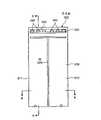
导光板300由矩形的导光主框架310制成,而该导光主框架310则采用(但不限于)丙烯酸板制成。导光主框架310的大小和形状与矩形凹部222的大小和形状基本相同。如上所述,由于在导光主框架310大致中央部位处形成的缝320,导光板300被分成大小基本相同的第一导光区域311和第二导光区域312。The
导光主框架310的顶部形成有线状光源区域330。线状光源区域330中设置有多个LED 340(在图2、4、6中为六个LED 340)。所述六个LED340被划分成两个发光组,即由前三个LED 340组成的第一发光组和由其余三个LED 340组成的第二发光组。第一导光区域311能够直线地引导第一发光组中的LED 340发射的光,而第二导光区域312能够直线地引导第二发光组中的LED 340发射的光。A linear
因此,由于导光板300中的缝320,以使得可以对导光板300上的导光区域进行分区的方式对照射到导光板300的光进行阻挡。因此,基于导光板300,以及第一发光组中的LED 340和第二发光组中的LED 340的点亮与关断的组合,可以实现间歇或连续的分区照明或整体照明。Accordingly, due to the
更具体地说,为了对导光板300进行整体照明,同时点亮第一发光组和第二发光组中的LED 340。另一方面,为了对导光板300进行局部照明,点亮或熄灭第一发光组和第二发光组中的任一组中的LED 340。这样的配置使得可以仅使用单个导光板300而对后面板350进行整体照明或局部照明。More specifically, in order to illuminate the
具有低蔽光性的白色片354(见图2)固定接合至导光板300的后侧。白色片354用作反射片,以防止来自第一导光区域311和第二导光区域312的光发生光衰减。A white sheet 354 (see FIG. 2 ) having a low light-shielding property is fixedly bonded to the rear side of the
而且,由于白色片354设置在导光板300和LED显示单元360之间,因此从LED显示单元360发出并从后侧进入导光板300的光透过导光板300(见图7A)。这产生了因光的交叠而造成的照明效果。Also, since the
这样,由于白色片354,导光板300还能够引导设于该导光板300下方的LED显示单元360发出的光。In this way, due to the
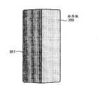
后面板350被制成具有与导光板300基本相同的大小和形状。围绕主面板体351的后表面接合有黑色的遮光框架352,围绕遮光框架352贴有遮光缘353(见图5B)。因为遮光框架352和遮光缘353,除了遮光外,还可以对从后面板350的边缘发出的光的强度进行控制。The
图8是通过导光板300对后面板350进行照明(整体照明)的示意图。图9是通过导光板300对后面板350进行照明(分区照明)的示意图。在图8和图9中,标有斜线的区域为后面板350上被由第一导光区域311和第二导光区域312(见图6)中的任一个或全部两个所引导的光照明的区域。FIG. 8 is a schematic diagram of illuminating the
如图8和图9所示,使用缝320将导光板300分成第一导光区域311和第二导光区域312。第一发光组中的LED 340被设置成与第一导光区域311相对应。第二发光组中的LED 340被设置成与第二导光区域312相对应。在图8中,情况(1)表示第一发光组和第二发光组中的LED 340均熄灭。因此,后面板350未以照明状态示出。情况(2)表示第一发光组和第二发光组中的LED 340均已点亮。因此,后面板350被示出为被整体照明。As shown in FIGS. 8 and 9 , the
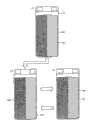
类似地,在图9中,情况(1)表示第一发光组和第二发光组中的LED 340均熄灭。情况(2)表示只有第一发光组中的LED 340点亮。因此,只有后面板350的左边区域示出为被照明。情况(3)表示只有第二发光组中的LED 340被点亮。因此,仅后面板350的右边区域示出为被照明。按照这种方式,通过交替地点亮第一发光组中的LED 340和第二发光组中的LED 340,可以交替地照明后面板350的左边区域和右边区域。Similarly, in FIG. 9, situation (1) represents that the
因此,通过间歇和交替地进行图8的情况(1)和(2)所示的对后面板350的整体照明,以及图9的情况(1)、(2)和(3)所示的对后面板350的分区照明,可以产生各种照明效果。Therefore, by intermittently and alternately performing the overall illumination of the
而且,当LCD模块224中的LED显示单元360点亮时,LED显示单元360的透过导光板300的时间或设计的LED显示画面以及第一导光区域311和第二导光区域312的照明可以被组合,从而有效地产生照明效果。Moreover, when the
总而言之,在根据第一实施方式的蜂窝电话10中,导光板300直线地引导多个光源(即,LED 340)所发射的光。导光板300和显示预定的LED显示画面的LED显示单元360层叠布置在活动侧外壳200中。由于形成在导光板300的大致中央部位处的缝320,导光板300被分成第一导光区域311和第二导光区域312。通过交替地点亮第一发光组中的LED340和第二发光组中的LED 340,可以交替照明第一导光区域311和第二导光区域312。按照这种方式,可以使用单个导光板300来实现分区照明,并有效地产生照明效果,而不必非得设置多个导光板300。In summary, in the
同时,尽管针对采用了图1所示的铰接结构来把活动侧外壳耦接到固定侧外壳的折叠式蜂窝电话进行了以上说明,但也可以采用图1所示的铰接结构以外的其它铰接结构。此外,代替折叠式蜂窝电话,上述说明也可适用于采用具有滑动结构或转动结构的耦接单元将活动侧外壳交叠地耦接到固定侧外壳的蜂窝电话。Meanwhile, although the above description has been made for the foldable cellular phone employing the hinge structure shown in FIG. 1 to couple the movable-side housing to the fixed-side housing, other hinge structures than the hinge structure shown in FIG. 1 may also be employed. . Furthermore, instead of a folder-type cellular phone, the above description is also applicable to a cellular phone overlappingly coupling a movable-side housing to a fixed-side housing using a coupling unit having a sliding structure or a rotating structure.
第一实施方式中的移动终端装置被设定为蜂窝电话。然而,上述说明也可实现为小型信息处理装置如个人数字助理(PDA)、小型音乐播放器、便携式电视机或手持式游戏装置中的发光板的发光结构。The mobile terminal device in the first embodiment is set as a cellular phone. However, the above description can also be implemented as a light-emitting structure of a light-emitting panel in a small information processing device such as a personal digital assistant (PDA), a small music player, a portable TV, or a handheld game device.
按照这种方式,根据该实施方式,移动终端装置包括使用缝分成第一导光区域和第二导光区域的导光板。为了对导光板进行整体照明,同时点亮第一导光区域和第二导光区域中的发光器件(LED)。另一方面,为对导光板进行局部照明,点亮第一导光区域和第二导光区域中的任一个中的发光器件(LED)。这样的配置使得可以使用单个导光板对后面板进行分区照明。这导致了部件数量的减少、移动终端装置结构的简化,以及制造成本的降低。In this way, according to this embodiment, the mobile terminal device includes the light guide plate divided into the first light guide area and the second light guide area using the slit. In order to illuminate the light guide plate as a whole, light emitting devices (LEDs) in the first light guide area and the second light guide area are simultaneously turned on. On the other hand, in order to partially illuminate the light guide plate, light emitting devices (LEDs) in any one of the first light guide area and the second light guide area are turned on. Such a configuration makes it possible to use a single light guide plate for zoned lighting of the rear panel. This results in a reduction in the number of parts, a simplification of the structure of the mobile terminal device, and a reduction in manufacturing costs.
在此引用的所有实施例和条件语言都是出于教导目的,以帮助读者理解本发明的原理和发明人为了改进技术而贡献的概念,并且应被视为不限于这些具体描述的实施例和条件,在说明书中这些实施例的组织也涉及表明本发明的优劣。尽管详细描述了本发明的实施方式,但应当理解,可以在不偏离本发明的精神和范围的前提下,对本发明进行各种变更、替换和更改。All examples and conditional language cited herein are for instructional purposes to assist the reader in understanding the principles of the invention and concepts contributed by the inventors to improve the art, and should not be construed as limited to these specifically described examples and Conditions, the organization of these examples in the specification are also referred to demonstrate the advantages and disadvantages of the present invention. Although the embodiments of the present invention have been described in detail, it should be understood that the various changes, substitutions and alterations could be made hereto without departing from the spirit and scope of the invention.
本申请基于2008年4月28日提交的第2008-117852号的在先日本专利申请,并要求其优先权,通过引用将该在先日本专利申请的整个内容并入于此。This application is based on and claims priority from prior Japanese Patent Application No. 2008-117852 filed on April 28, 2008, the entire contents of which are hereby incorporated by reference.
Claims (9)
Translated fromChineseApplications Claiming Priority (3)
| Application Number | Priority Date | Filing Date | Title |
|---|---|---|---|
| JP2008-117852 | 2008-04-28 | ||
| JP2008117852AJP5077052B2 (en) | 2008-04-28 | 2008-04-28 | Mobile terminal device |
| JP2008117852 | 2008-04-28 |
Publications (2)
| Publication Number | Publication Date |
|---|---|
| CN101572733A CN101572733A (en) | 2009-11-04 |
| CN101572733Btrue CN101572733B (en) | 2012-05-23 |
Family
ID=41214311
Family Applications (1)
| Application Number | Title | Priority Date | Filing Date |
|---|---|---|---|
| CN2009100032302AExpired - Fee RelatedCN101572733B (en) | 2008-04-28 | 2009-01-21 | Mobile terminal device |
Country Status (3)
| Country | Link |
|---|---|
| US (1) | US7824047B2 (en) |
| JP (1) | JP5077052B2 (en) |
| CN (1) | CN101572733B (en) |
Families Citing this family (2)
| Publication number | Priority date | Publication date | Assignee | Title |
|---|---|---|---|---|
| CN103516833A (en)* | 2012-06-25 | 2014-01-15 | 苏州经贸职业技术学院 | Light obscuration device for mobile phone screen |
| KR101685989B1 (en) | 2016-01-04 | 2016-12-13 | 엘지전자 주식회사 | Mobile terminal |
Citations (2)
| Publication number | Priority date | Publication date | Assignee | Title |
|---|---|---|---|---|
| CN1403852A (en)* | 2001-09-06 | 2003-03-19 | 精工爱普生株式会社 | Light guides, electro-optic devices and electronic devices |
| CN1821847A (en)* | 2005-02-18 | 2006-08-23 | 夏普株式会社 | Light guide plate, light guide device, lighting device, light guide system and driving circuit |
Family Cites Families (11)
| Publication number | Priority date | Publication date | Assignee | Title |
|---|---|---|---|---|
| US4674827A (en)* | 1982-05-20 | 1987-06-23 | Masayuki Izutsu | Slab-type optical device |
| US5438484A (en)* | 1991-12-06 | 1995-08-01 | Canon Kabushiki Kaisha | Surface lighting device and a display having such a lighting device |
| JPH06318897A (en) | 1993-05-07 | 1994-11-15 | Murata Mach Ltd | Portable telephone set |
| US6046730A (en)* | 1996-03-15 | 2000-04-04 | At&T Corp | Backlighting scheme for a multimedia terminal keypad |
| GB2334807A (en)* | 1998-02-27 | 1999-09-01 | Nokia Mobile Phones Ltd | Display assembly |
| US6874926B2 (en)* | 2001-11-26 | 2005-04-05 | Nokia Corporation | Illumination system for an electronic device |
| FI20012484A0 (en)* | 2001-12-17 | 2001-12-17 | Nokia Corp | Liquid crystal display |
| US20060187676A1 (en)* | 2005-02-18 | 2006-08-24 | Sharp Kabushiki Kaisha | Light guide plate, light guide device, lighting device, light guide system, and drive circuit |
| KR101121715B1 (en)* | 2005-03-18 | 2012-03-09 | 서울반도체 주식회사 | Mobile communication terminal having a light guide for indicating the receipt of a message |
| JP2007122971A (en)* | 2005-10-26 | 2007-05-17 | Sharp Corp | Surface light source device and image display device using the same |
| JP4687904B2 (en)* | 2006-07-10 | 2011-05-25 | 日本電気株式会社 | Folding mobile phone terminal |
- 2008
- 2008-04-28JPJP2008117852Apatent/JP5077052B2/ennot_activeExpired - Fee Related
- 2008-12-30USUS12/318,523patent/US7824047B2/ennot_activeExpired - Fee Related
- 2009
- 2009-01-21CNCN2009100032302Apatent/CN101572733B/ennot_activeExpired - Fee Related
Patent Citations (2)
| Publication number | Priority date | Publication date | Assignee | Title |
|---|---|---|---|---|
| CN1403852A (en)* | 2001-09-06 | 2003-03-19 | 精工爱普生株式会社 | Light guides, electro-optic devices and electronic devices |
| CN1821847A (en)* | 2005-02-18 | 2006-08-23 | 夏普株式会社 | Light guide plate, light guide device, lighting device, light guide system and driving circuit |
Also Published As
| Publication number | Publication date |
|---|---|
| CN101572733A (en) | 2009-11-04 |
| US7824047B2 (en) | 2010-11-02 |
| US20090267506A1 (en) | 2009-10-29 |
| JP5077052B2 (en) | 2012-11-21 |
| JP2009267983A (en) | 2009-11-12 |
Similar Documents
| Publication | Publication Date | Title |
|---|---|---|
| US7034799B2 (en) | Backlighting device for dual liquid crystal display and folder-type mobile phone therewith | |
| JP5120028B2 (en) | Mobile terminal device | |
| JP5493858B2 (en) | Mobile phone | |
| CN101755317A (en) | Structure for illuminating key operation section, electronic device, mobile device and method for illuminating key operation section | |
| JP4580432B2 (en) | KEY PRESSING DETECTION DEVICE, AND ELECTRONIC DEVICE AND COMMUNICATION DEVICE HAVING THE SAME | |
| US20090266691A1 (en) | Mobile terminal device | |
| CN101572733B (en) | Mobile terminal device | |
| JP4687904B2 (en) | Folding mobile phone terminal | |
| TWI398686B (en) | Dual display module | |
| US8367948B2 (en) | Handheld device | |
| JP5178427B2 (en) | Display device and electronic apparatus | |
| JP5125578B2 (en) | Mobile terminal device | |
| JP2008182608A (en) | Mobile device | |
| JP2010170999A (en) | Light source device and electronic apparatus | |
| JP5108920B2 (en) | KEY PRESSING DETECTION DEVICE, AND ELECTRONIC DEVICE AND COMMUNICATION DEVICE HAVING THE SAME | |
| JPH06318897A (en) | Portable telephone set | |
| JP4941346B2 (en) | Electronics | |
| JP5275294B2 (en) | Key press detection device | |
| JP4699404B2 (en) | Portable electronic devices | |
| KR20090003906A (en) | Handheld terminal | |
| JP2008182658A (en) | Mobile device | |
| JP2009059544A (en) | Light guide, and electronic apparatus | |
| WO2010007967A1 (en) | Key input device, and mobile terminal | |
| JP2010200035A (en) | Portable terminal, and side key illumination method | |
| JP2010226551A (en) | Portable electronic devices |
Legal Events
| Date | Code | Title | Description |
|---|---|---|---|
| C06 | Publication | ||
| PB01 | Publication | ||
| C10 | Entry into substantive examination | ||
| SE01 | Entry into force of request for substantive examination | ||
| C14 | Grant of patent or utility model | ||
| GR01 | Patent grant | ||
| CF01 | Termination of patent right due to non-payment of annual fee | ||
| CF01 | Termination of patent right due to non-payment of annual fee | Granted publication date:20120523 Termination date:20200121 |