CN101569199B - Method and device for reducing block distortion - Google Patents
Method and device for reducing block distortionDownload PDFInfo
- Publication number
- CN101569199B CN101569199BCN2008800012590ACN200880001259ACN101569199BCN 101569199 BCN101569199 BCN 101569199BCN 2008800012590 ACN2008800012590 ACN 2008800012590ACN 200880001259 ACN200880001259 ACN 200880001259ACN 101569199 BCN101569199 BCN 101569199B
- Authority
- CN
- China
- Prior art keywords
- pixel
- value
- pass filter
- block distortion
- low
- Prior art date
- Legal status (The legal status is an assumption and is not a legal conclusion. Google has not performed a legal analysis and makes no representation as to the accuracy of the status listed.)
- Expired - Fee Related
Links
Images


Classifications
- H—ELECTRICITY
- H04—ELECTRIC COMMUNICATION TECHNIQUE
- H04N—PICTORIAL COMMUNICATION, e.g. TELEVISION
- H04N19/00—Methods or arrangements for coding, decoding, compressing or decompressing digital video signals
- H04N19/10—Methods or arrangements for coding, decoding, compressing or decompressing digital video signals using adaptive coding
- H04N19/102—Methods or arrangements for coding, decoding, compressing or decompressing digital video signals using adaptive coding characterised by the element, parameter or selection affected or controlled by the adaptive coding
- H04N19/117—Filters, e.g. for pre-processing or post-processing
- H—ELECTRICITY
- H04—ELECTRIC COMMUNICATION TECHNIQUE
- H04N—PICTORIAL COMMUNICATION, e.g. TELEVISION
- H04N19/00—Methods or arrangements for coding, decoding, compressing or decompressing digital video signals
- H04N19/10—Methods or arrangements for coding, decoding, compressing or decompressing digital video signals using adaptive coding
- H04N19/134—Methods or arrangements for coding, decoding, compressing or decompressing digital video signals using adaptive coding characterised by the element, parameter or criterion affecting or controlling the adaptive coding
- H04N19/136—Incoming video signal characteristics or properties
- H04N19/14—Coding unit complexity, e.g. amount of activity or edge presence estimation
- H—ELECTRICITY
- H04—ELECTRIC COMMUNICATION TECHNIQUE
- H04N—PICTORIAL COMMUNICATION, e.g. TELEVISION
- H04N19/00—Methods or arrangements for coding, decoding, compressing or decompressing digital video signals
- H04N19/10—Methods or arrangements for coding, decoding, compressing or decompressing digital video signals using adaptive coding
- H04N19/169—Methods or arrangements for coding, decoding, compressing or decompressing digital video signals using adaptive coding characterised by the coding unit, i.e. the structural portion or semantic portion of the video signal being the object or the subject of the adaptive coding
- H04N19/17—Methods or arrangements for coding, decoding, compressing or decompressing digital video signals using adaptive coding characterised by the coding unit, i.e. the structural portion or semantic portion of the video signal being the object or the subject of the adaptive coding the unit being an image region, e.g. an object
- H04N19/176—Methods or arrangements for coding, decoding, compressing or decompressing digital video signals using adaptive coding characterised by the coding unit, i.e. the structural portion or semantic portion of the video signal being the object or the subject of the adaptive coding the unit being an image region, e.g. an object the region being a block, e.g. a macroblock
- H—ELECTRICITY
- H04—ELECTRIC COMMUNICATION TECHNIQUE
- H04N—PICTORIAL COMMUNICATION, e.g. TELEVISION
- H04N19/00—Methods or arrangements for coding, decoding, compressing or decompressing digital video signals
- H04N19/60—Methods or arrangements for coding, decoding, compressing or decompressing digital video signals using transform coding
- H04N19/61—Methods or arrangements for coding, decoding, compressing or decompressing digital video signals using transform coding in combination with predictive coding
- H—ELECTRICITY
- H04—ELECTRIC COMMUNICATION TECHNIQUE
- H04N—PICTORIAL COMMUNICATION, e.g. TELEVISION
- H04N19/00—Methods or arrangements for coding, decoding, compressing or decompressing digital video signals
- H04N19/80—Details of filtering operations specially adapted for video compression, e.g. for pixel interpolation
- H—ELECTRICITY
- H04—ELECTRIC COMMUNICATION TECHNIQUE
- H04N—PICTORIAL COMMUNICATION, e.g. TELEVISION
- H04N19/00—Methods or arrangements for coding, decoding, compressing or decompressing digital video signals
- H04N19/85—Methods or arrangements for coding, decoding, compressing or decompressing digital video signals using pre-processing or post-processing specially adapted for video compression
- H04N19/86—Methods or arrangements for coding, decoding, compressing or decompressing digital video signals using pre-processing or post-processing specially adapted for video compression involving reduction of coding artifacts, e.g. of blockiness
Landscapes
- Engineering & Computer Science (AREA)
- Multimedia (AREA)
- Signal Processing (AREA)
- Compression Or Coding Systems Of Tv Signals (AREA)
- Image Processing (AREA)
- Picture Signal Circuits (AREA)
- Compression Of Band Width Or Redundancy In Fax (AREA)
Abstract
Translated fromChinese
Description
Translated fromChinese技术领域technical field
本发明涉及通过使用自适应滤波器(adaptive filter),提高图像的品质,计算与块边界附近的像素相关的调整后的值的装置以及方法。更详细而言,本发明涉及消除块状噪声的自适应滤波器。块状噪声例如像JPEG文件那样在静止图像被压缩时,或例如像MPEG文件那样在视频被压缩时产生。这些压缩后的图像在电影、广播节目以及多媒体流中得到广泛使用。本发明取得具有块状噪声的图像,随后通过使用上述自适应滤波器提高图像品质,求出与块边界附近的像素相关的调整后的值。自适应滤波器包括用于计算权重的高通滤波器,和用于计算减少块边界附近的像素的不连续性的滤波值的低通滤波器。自适应滤波器通过计算原始像素值与滤波值的加权和,决定调整后的值。本发明能够在DVD播放器、数码相机等图像处理装置,计算机程序以及LCD、PDP及CRT等图像显示装置中使用。 The present invention relates to an apparatus and method for calculating adjusted values related to pixels near block boundaries by using an adaptive filter to improve image quality. More specifically, the present invention relates to adaptive filters for removing block noise. Block noise is generated when a still image is compressed, for example, as in a JPEG file, or when a video is compressed, for example, as in an MPEG file. These compressed images are widely used in movies, radio shows, and multimedia streaming. The present invention obtains an image with block noise, then improves the image quality by using the adaptive filter described above, and obtains adjusted values related to pixels near the block boundary. The adaptive filter includes a high-pass filter for calculating weights, and a low-pass filter for calculating filter values that reduce discontinuity of pixels near block boundaries. The adaptive filter determines the adjusted value by calculating the weighted sum of the original pixel value and the filtered value. The present invention can be used in image processing devices such as DVD players and digital cameras, computer programs, and image display devices such as LCDs, PDPs, and CRTs. the
背景技术Background technique
专利文献1的以往例子揭示了使用多个块编码动态图像的方法。该方法包括:决定块边界周边的S0、S1、S2的像素集合的步骤;在取得模式决定值后,按照块状噪声的程度,作为默认模式或DC偏置模式,选择性地决定去块模式(deblocking mode)的步骤;在决定默认模式的情况下,使用4点DCT核,对每个像素取得块边界周边的频率信息的步骤;将属于块边界的非连续要素的大小替换为属于频域中的块边界周围的非连续要素的最小大小的步骤;将该替换步骤应用于空间域的步骤;在决定DC偏置模式的情况下,判断是否需要执行该DC偏置模式的步骤;以及若通过该步骤判断为需要执行DC偏置模式,则在光滑区域中消除块状噪声的步骤。表示该以往例子的处理的流程图在图1中表示。 The conventional example of
专利文献1:美国专利6240135号公报 Patent Document 1: U.S. Patent No. 6,240,135
发明内容Contents of the invention
发明要解决的问题 The problem to be solved by the invention
该以往例子通过使用两个模式,即默认模式与DC偏置模式,调整形成块状噪声的像素值。在该默认模式中,通过使用4点DCT核取得每个像素的块边界周边的频率信息。属于该块边界的非连续要素的大小被替换为属于频域中的块边界周围的非连续要素的最小大小。在DC偏置模式中,执行低通滤波。在默认模式中,仅补偿边界像素值。这样,默认模式对于消除照片中的设定等非常光滑的区域中的块状噪声是不够的。因此,光滑区域中的块状噪声通过DC偏置模式消除。 This conventional example adjusts pixel values that form block noise by using two modes, ie, the default mode and the DC bias mode. In this default mode, frequency information around the block boundary of each pixel is obtained by using a 4-point DCT kernel. The size of the non-contiguous features belonging to the block boundary is replaced by the minimum size of the non-contiguous features belonging to the surrounding block boundary in the frequency domain. In DC bias mode, low-pass filtering is performed. In the default mode, only boundary pixel values are compensated. As such, the default mode is not sufficient for removing blocky noise in very smooth areas such as settings in photos. Therefore, blocky noise in smooth areas is eliminated by DC bias mode. the
该以往例子将基于DCT的滤波器或低通滤波器应用于沿着块边界的像素,使非常光滑的区域造成的不连续性变得平滑。低通滤波器在非常光滑的区域中使用,基于DCT的滤波器在其他种类的区域中使用。块边界周边的像素间的差异通过使用这样的滤波器而减少,因此能够减少不连续性,消除块状噪声。但是,基于DCT的滤波器或低通滤波器不仅减少异常的不连续性,还消除像素间的自然变化。消除像素间的自然变化的结果是失去了鲜明度。该以往例子使用基于DCT的滤波器或低通滤波器消除块状噪声和不鲜明的状态。其结果是,像素的价值会降低。 This prior example applies a DCT-based filter or low-pass filter to pixels along block boundaries, smoothing discontinuities caused by very smooth regions. Low pass filters are used in very smooth regions, DCT based filters are used in other kinds of regions. By using such a filter, the difference between pixels around the block boundary is reduced, so that discontinuity can be reduced and block noise can be eliminated. However, DCT-based filters or low-pass filters not only reduce unusual discontinuities, but also remove natural variations between pixels. The result of eliminating the natural variation between pixels is a loss of sharpness. This conventional example uses a DCT-based filter or a low-pass filter to remove block noise and unsharp states. As a result, the value of the pixels will decrease. the
在像素的值沿着块边界形成异常的不连续性时,在块边界中产生块状噪声。以往的方法将基于DCT的滤波器或低通滤波器应用于沿着块边界的像素,使不连续性变得光滑。但是,基于DCT的滤波器或低通滤波器不仅减少异常的不连续性,还消除像素间的自然变化。使用消除块状噪声的以往方法,图像变得不鲜明,并且图像的品质会恶化。 Block noise is generated in block boundaries when values of pixels form abnormal discontinuities along block boundaries. Previous methods apply DCT-based filters or low-pass filters to pixels along block boundaries to smooth discontinuities. However, DCT-based filters or low-pass filters not only reduce unusual discontinuities, but also remove natural variations between pixels. With the conventional method of removing block noise, the image becomes unclear and the quality of the image deteriorates. the
用于解决问题的手段 means for solving problems
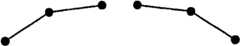
在本发明中,通过使用自适应滤波器,减少块边界附近的异常的不连续性。在自适应滤波器中,块边界附近的像素的权重通过使用高通滤波器求出,使用权重求出与块边界附近的像素相关的调整后的值。应用于块边界各侧的像素的高通滤波器识别块边界附近的像素的特征。在连接关注像素与位于其两邻的像素的亮度电平的线为倒V字型的情况下,高通滤波值为正值,另一方面,为V字型的情况下,高通滤波值为负值。高通滤波值的绝对值越大,表示倒V字型或V字型的弯折角度为越尖锐的角。另外, 关注像素是位于与块边界线相邻的位置的像素。另外,为了视觉上容易理解,定义了“倒V字型”、“V字型”,也可以将作为平滑连接关注像素与位于其两邻的像素的近似曲线或近似直线的函数的二次微分值为负的情况称为倒V字型,将二次微分值为正的情况称为V字型。在此情况下,所谓倒V字型、V字型的弯折角度为较尖锐的角,表现为二次微分值的绝对值较大。 In the present invention, abnormal discontinuities near block boundaries are reduced by using an adaptive filter. In the adaptive filter, the weight of the pixels near the block boundary is obtained by using a high-pass filter, and the adjusted value of the pixel near the block boundary is obtained using the weight. A high-pass filter applied to pixels on either side of the block boundary identifies characteristics of pixels near the block boundary. If the line connecting the luminance levels of the pixel of interest and the pixels adjacent to it has an inverted V-shape, the high-pass filter value is positive; on the other hand, if the line is V-shaped, the high-pass filter value is negative. value. The larger the absolute value of the high-pass filter value, the sharper the inverted V-shape or the bending angle of the V-shape. In addition, the pixel of interest is a pixel located adjacent to the block boundary line. In addition, "inverted V-shape" and "V-shape" are defined for visual understanding, and the quadratic differential of a function that smoothly connects the pixel of interest and the pixels located on both sides of the approximate curve or approximate straight line can also be used A case where the value is negative is called an inverted V-shape, and a case where the value of the second differential is positive is called a V-shape. In this case, the so-called inverted V-shape and V-shape bend angle are relatively sharp angles, and the absolute value of the quadratic differential value is large. the
随后,连续像素的鲜明度能够由高通滤波器的输出电平识别。高通滤波器的输出电平意味着连续像素的变化程度。高电平的输出意味着形成峰值的高鲜明度。相反,低电平的输出意味着形成非峰值形状的低鲜明度。根据高通滤波器的输出,推测像素间的自然变化以及异常的不连续性。自适应滤波器通过使用利用高通滤波器求出的权重,计算与块边界附近的像素相关的调整后的值。计算与块边界附近的像素相关的调整后的值后,通过自适应滤波器,经由权重来识别并研究块边界附近的像素的特征。 Subsequently, the sharpness of consecutive pixels can be identified by the output level of the high-pass filter. The output level of the high-pass filter means the degree of variation of successive pixels. High level output means high definition peaking. Conversely, a low level of output means low sharpness resulting in off-peak shapes. From the output of the high-pass filter, natural variations between pixels and unusual discontinuities are inferred. The adaptive filter calculates adjusted values for pixels near the block boundary by using weights obtained by the high-pass filter. After computing the adjusted values associated with the pixels near the block border, the features of the pixels near the block border are identified and investigated via weights through an adaptive filter. the
发明效果 Invention effect
因此,本发明减少异常的不连续性,保持块边界附近的自然变化。图像的品质在消除块状噪声时能够得到提高。 Thus, the present invention reduces anomalous discontinuities, preserving natural variations near block boundaries. Image quality can be improved when blocking noise is removed. the
在原图像中,与轮廓线垂直相邻的两个像素的亮度电平表现出较大的差。在该轮廓线和块与块的边界线一致的情况下,利用消除块状噪声的低通滤波器,轮廓线变为具有渐变性的平滑的亮度变化后,轮廓线变得模糊,原图像的鲜明度受到损失。但是,在本发明中,在认为轮廓线和块与块的边界线一致的情况下,调整低通滤波器的滤波值,能够使轮廓线不模糊。 In the original image, the luminance levels of two pixels vertically adjacent to the contour line show a large difference. In the case where the contour line coincides with the boundary line of the block and the block, the contour line becomes blurred after the low-pass filter that eliminates the block noise, and the brightness of the original image changes gradually. Sharpness is lost. However, in the present invention, when it is considered that the contour line coincides with the boundary line between blocks, the filter value of the low-pass filter is adjusted so that the contour line is not blurred. the
附图说明Description of drawings
图1是表示以往例子的处理的流程图。 FIG. 1 is a flowchart showing processing in a conventional example. the
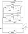
图2是表示本发明的减少块状噪声的装置的模块图。 Fig. 2 is a block diagram showing the device for reducing block noise of the present invention. the
图3是表示本发明的自适应滤波器200的计算流程的流程图。 FIG. 3 is a flowchart showing the calculation flow of the
图4是表示本发明的减少块状噪声的装置的另一例子的模块图。 FIG. 4 is a block diagram showing another example of the apparatus for reducing block noise of the present invention. the
图5是表示本发明的减少块状噪声的装置中图4的例子的计算流程的流程图。 FIG. 5 is a flow chart showing the calculation flow of the example shown in FIG. 4 in the apparatus for reducing block noise according to the present invention. the
图6是表示本发明的减少块状噪声的装置的第一实施例的模块图。 FIG. 6 is a block diagram showing a first embodiment of the device for reducing block noise of the present invention. the
图7是表示包括连续的水平像素的输入图像数据的例子的模式图。 FIG. 7 is a schematic diagram showing an example of input image data including consecutive horizontal pixels. the
图8是表示本发明的自适应滤波器600的计算流程的流程图。 FIG. 8 is a flowchart showing the calculation flow of the adaptive filter 600 of the present invention. the
图9A是表示本发明的高通滤波器的符号的模式图。 FIG. 9A is a schematic diagram showing symbols of a high-pass filter of the present invention. the
图9B是表示本发明的高通滤波器的符号的模式图。 Fig. 9B is a schematic diagram showing symbols of the high-pass filter of the present invention. the
图10A是表示本发明的高通滤波器的鲜明度的模式图。 Fig. 10A is a schematic diagram showing the sharpness of the high-pass filter of the present invention. the
图10B是表示本发明的高通滤波器的鲜明度的模式图。 Fig. 10B is a schematic diagram showing the sharpness of the high-pass filter of the present invention. the
图11A是表示本发明的低通滤波器的动作的模式图。 FIG. 11A is a schematic diagram showing the operation of the low-pass filter of the present invention. the
图11B是表示本发明的低通滤波器的动作的模式图。 FIG. 11B is a schematic diagram showing the operation of the low-pass filter of the present invention. the
图11C是表示本发明的低通滤波器的动作的模式图。 Fig. 11C is a schematic diagram showing the operation of the low-pass filter of the present invention. the
图11D是表示本发明的低通滤波器的动作的模式图。 Fig. 11D is a schematic diagram showing the operation of the low-pass filter of the present invention. the
图11E是表示本发明的低通滤波器的动作的模式图。 Fig. 11E is a schematic diagram showing the operation of the low-pass filter of the present invention. the
图11F是表示本发明的低通滤波器的动作的模式图。 FIG. 11F is a schematic diagram showing the operation of the low-pass filter of the present invention. the
图12A是表示本发明的自适应滤波器的动作的模式图。 Fig. 12A is a schematic diagram showing the operation of the adaptive filter of the present invention. the
图12B是表示本发明的自适应滤波器的动作的模式图。 Fig. 12B is a schematic diagram showing the operation of the adaptive filter of the present invention. the
图12C是表示本发明的自适应滤波器的动作的模式图。 Fig. 12C is a schematic diagram showing the operation of the adaptive filter of the present invention. the
图12D是表示本发明的自适应滤波器的动作的模式图。 Fig. 12D is a schematic diagram showing the operation of the adaptive filter of the present invention. the
图12E是表示本发明的自适应滤波器的动作的模式图。 Fig. 12E is a schematic diagram showing the operation of the adaptive filter of the present invention. the
图12F是表示本发明的自适应滤波器的动作的模式图。 Fig. 12F is a schematic diagram showing the operation of the adaptive filter of the present invention. the
图13是表示本发明中消除块状噪声的动作的模式图。 Fig. 13 is a schematic diagram showing the block noise canceling operation in the present invention. the
图14是表示本发明中消除块状噪声的动作的模式图。 Fig. 14 is a schematic diagram showing the block noise canceling operation in the present invention. the
图15是表示本发明中消除块状噪声的动作的模式图。 Fig. 15 is a schematic diagram showing the block noise canceling operation in the present invention. the
图16是本发明的减少块状噪声的装置中的模块图。 Fig. 16 is a block diagram of the device for reducing block noise of the present invention. the
图17是表示本发明的减少块状噪声的装置中图16的例子的计算流程的流程图。 FIG. 17 is a flowchart showing the calculation flow of the example in FIG. 16 in the apparatus for reducing block noise of the present invention. the
符号说明 Symbol Description
200自适应滤波器 201计算单元 202决定单元 402检测单元403切换器 603高通滤波器 604权重计算单元 605低通滤波器606加权和计算单元 200
具体实施方式Detailed ways
下面,参照图2所示的模块图说明消除块状噪声的装置。消除块状噪声的装置包括计算调整后的值的自适应滤波器200。自适应滤波器200进一步包括通过高通滤波器计算权重的计算单元201,和通过使用权重来决定块边界附近的像素值的决定单元202。 Next, an apparatus for eliminating block noise will be described with reference to the block diagram shown in FIG. 2 . The means for removing block noise includes an
自适应滤波器200取得输入图像数据,输出调整后的值。在自适应滤波器200中,计算单元201通过使用应用于横穿块边界设置的多个像素的高通滤波器的输出,计算块边界附近的像素的权重。像素的权重被输出到决定单元202。决定单元202取得输入图像数据以及计算单元201的输出,通过使用原始像素值和像素的权重,决定调整后的值。 The
自适应滤波器200的计算流程在图3中表示。块边界附近的像素的权重在步骤301中通过使用高通滤波器计算。步骤301中计算的权重在步骤302中用于决定与块边界附近的像素相关的调整后的值。 The calculation flow of the
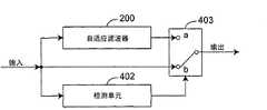
消除块状噪声的装置还包括图4所示的检测单元402以及切换器403。自适应滤波器200除了输出之外与图2的上述自适应滤波器200相同,与切换器403连接。检测单元402取得输入图像数据,检测形成块状噪声的噪声像素。检测单元402的输出与切换器403连接。切换器403取得输入图像数据、自适应滤波器200的输出以及检测单元402的输出。切换器403按照检测单元402的输出,输出输入图像数据的原始像素值或者从自适应滤波器200输出的调整后的值。若检测单元402检测出了形成块状噪声的噪声像素,则切换器403输出调整后的值。否则,切换器403输出原始像素值。 The device for eliminating block noise further includes a
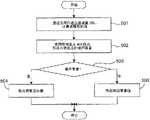
图5中表示计算流程。与块边界附近的像素相关的调整后的值在步骤501中通过使用自适应滤波器200计算。检测单元402在步骤502中检测形成块状噪声的噪声像素。切换器403的计算参照步骤503、504以及505。通过确认像素是否为噪声像素,在步骤503中分离为两个步骤。若检测出噪声像素,则进入步骤504,进一步输出调整后的值。否则,进入步骤505,进一步输出原始像素值。此外,步骤501及步骤502的顺序不影响处理的结果,因此能够交换步骤501及步骤502的顺序,此外两个步骤也能同时计算。 The calculation flow is shown in FIG. 5 . Adjusted values associated with pixels near the block border are calculated in
(第一实施例) (first embodiment)
参照图6以及图8说明本发明的第一实施例。第一实施例的模块图在图6中表示。第一实施例包括用于计算调整后的值的自适应滤波器200。自适应滤波器200进一步包括计算权重的计算单元201,和使用权重决定块边界附近的像素值的决定单元202。 A first embodiment of the present invention will be described with reference to FIGS. 6 and 8 . A block diagram of the first embodiment is shown in FIG. 6 . The first embodiment includes an
自适应滤波器200取得输入图像,输出调整后的值。在自适应滤波器200中,计算单元201取得输入图像数据,通过使用应用于横穿块边界设置的多个像素的高通滤波器的输出,计算块边界附近的像素的权重。计算单元201将权重输出到决定单元202。决定单元202取得输入图像数据和从计算单元201输出的权重,通过计算块边界附近的像素的加权和,决定调整后的值。 The
计算单元201进一步包括高通滤波器603以及权重计算单元604。高通滤波器603取得输入图像数据,对块边界各侧的像素进行滤波处理后输出到权重计算单元604。包括对像素进行水平及垂直滤波处理的高通滤波器603的系数的向量分别用式(1)及(2)表示。 The
[-1 2 -1] (1) [-1 2 -1] (1)
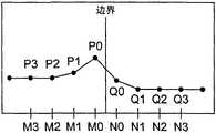
图7表示沿水平方向相邻的两个块的边界线、沿该边界线的左垂直方向排列的像素M0,M1,M2,M3以及沿右垂直方向排列的像素N0,N1,N2,N3。此外,P0,P1,P2,P3分别表示像素M0,M1,M2,M3的亮度电平,Q0,Q1,Q2,Q3分别表示像素N0,N1,N2,N3的亮度电平。 7 shows the boundary line of two adjacent blocks along the horizontal direction, pixels M0, M1, M2, M3 arranged vertically left along the boundary line, and pixels N0, N1, N2, N3 arranged vertically right along the boundary line. In addition, P0, P1, P2, and P3 represent the luminance levels of the pixels M0, M1, M2, and M3, respectively, and Q0, Q1, Q2, and Q3 represent the luminance levels of the pixels N0, N1, N2, and N3, respectively. the
高通滤波器603输出强调某个关注像素与和它相邻的两邻(左右或上下)的相邻像素的亮度电平的差的高通滤波值HPF。在该实施例中,高通滤波值HPF(Xi)的一般式用式(3)表示。 The high-
HPF(Xi)=[-1 2 -1][L(i-1)Li L(i+1)]THPF(Xi)=[-1 2 -1][L(i-1)Li L(i+1)]T
=(-1)*L(i-1)+(2)*Li+(-1)*L(i+1) (3) =(-1)*L(i-1)+(2)*Li+(-1)*L(i+1) (3)
在此,Li表示关注像素的亮度电平,L(i-1)、L(i+1)表示与关注像素相 邻的两邻(左右或上下)的相邻像素的亮度电平。 Here, Li represents the luminance level of the pixel of interest, and L(i-1) and L(i+1) represent the luminance levels of adjacent pixels adjacent to the pixel of interest (left, right or top and bottom). the
在图7中,在使关注像素为与边界线相邻的像素的情况下,像素M0的高通滤波值HPF(M0)由式(4)决定,像素N0的高通滤波值HPF(N0)由式(5)决定。 In Fig. 7, when the pixel of interest is a pixel adjacent to the boundary line, the high-pass filter value HPF(M0) of the pixel M0 is determined by formula (4), and the high-pass filter value HPF(N0) of the pixel N0 is determined by the formula (5) DECISION. the
HPF(M0)=[-1 2 -1][P1 P0 Q0]T (4) HPF(M0)=[-1 2 -1][P1 P0 Q0]T (4)
HPF(N0)=[-1 2 -1][P0 Q0 Q1]T (5) HPF(N0)=[-1 2 -1][P0 Q0 Q1]T (5)
权重计算单元604取得高通滤波器603的输出,通过式(6)、(7)、(8)以及(9)计算权重。 The
AM0=(HPF(M0)+HPF(N0))/HPF(M0) (6) AM0 = (HPF(M0)+HPF(N0))/HPF(M0) (6)
AN0=(HPF(N0)+HPF(M0))/HPF(N0) (7) AN0 = (HPF(N0)+HPF(M0))/HPF(N0) (7)
AMi=1,ifi≠0 (8) AMi = 1, ifi ≠ 0 (8)
ANi=1,ifi≠0 (9) ANi = 1, ifi ≠ 0 (9)
在此,AMi表示像素Mi的权重,HPF(Mi)表示像素Mi的作为高通滤波器603的输出的高通滤波值HPF(Mi)。权重被输出到用于决定调整后的值的决定单元202。像素M0的权重通过使用式(6)决定,像素N0的权重通过使用式(7)决定。式(8)表示M1,M2,M3,……的权重为1,式(9)表示N1,N2,N3,……的权重为1。 Here, AMi represents the weight of the pixel Mi, and HPF(Mi) represents the high-pass filter value HPF(Mi) of the pixel Mi that is the output of the high-
连续的垂直像素的计算与连续的水平像素的例子类似。由于描述会变得冗长,所以在此不重复描述。 The calculation of consecutive vertical pixels is similar to the case of consecutive horizontal pixels. Since the description would become lengthy, the description is not repeated here. the
在连接关注像素与位于其两邻的像素的亮度电平的线为倒V字型的情况下,高通滤波值为正值,另一方面,在V字型的情况下,高通滤波值为负值。高通滤波值的绝对值越大,表示倒V字型或V字型的弯折角度为越尖锐的角。另外,关注像素是位于与块边界线相邻的位置的像素。 If the line connecting the luminance levels of the pixel of interest and the pixels adjacent to it has an inverted V-shape, the high-pass filter value is positive. On the other hand, in the case of a V-shape, the high-pass filter value is negative. value. The larger the absolute value of the high-pass filter value, the sharper the inverted V-shape or the bending angle of the V-shape. In addition, the pixel of interest is a pixel located adjacent to the block boundary line. the
决定单元202进一步包括低通滤波器605和加权和计算单元606。低通滤波器605接收输入图像数据,应用于块边界附近的像素,决定滤波处 理后的值。包括用于对像素进行水平或垂直滤波处理的低通滤波器605的系数的向量如式(10a)及(10b)所示。 The
(1/4)[1 2 1] (10a) (1/4)[1 2 1] (10a)
低通滤波器605输出减少某个关注像素与和它相邻的两邻(左右或上下)的相邻像素的亮度电平的差的低通滤波值LPF。在该实施例中,低通滤波值LPF(Xi)的一般式用式(11)表示。 The low-
LPF(Xi)=(1/4)[1 2 1][L(i-1)Li L(i+1)]TLPF(Xi)=(1/4)[1 2 1][L(i-1)Li L(i+1)]T
=(1/4){(1)*L(i-1)+(2)*Li+(1)*L(i+1)} (11) =(1/4){(1)*L(i-1)+(2)*Li+(1)*L(i+1)} (11)
在此,LPF(M0)由式(12)决定,LPF(N0)由式(13)决定。 Here, LPF (M0) is determined by Equation (12), and LPF (N0) is determined by Equation (13). the
LPF(M0)=(1/4)[1 2 1][P1 P0 Q0]T (12) LPF(M0)=(1/4)[1 2 1][P1 P0 Q0]T (12)
LPF(N0)=(1/4)[1 2 1][P0 Q0 Q1]T (13) LPF(N0)=(1/4)[1 2 1][P0 Q0 Q1]T (13)
加权和计算单元606取得输入图像数据、作为低通滤波器605的输出的滤波处理后的值和作为权重计算单元604的输出的权重,通过基于式(14)计算原始像素值与滤波处理后的值的加权和,决定调整后的值。 The weighted
YK’=YK*AK+LPF(K)*(1-AK) (14) YK '=YK *AK +LPF(K)*(1-AK ) (14)
在此,YK’表示与像素K相关的调整后的亮度电平,YK表示像素K的原始的亮度电平,AK表示作为权重计算单元604的输出的像素K的权重。此外,LPF(K)表示像素K的滤波处理后的值,是像素K的低通滤波器605的输出。因此,M0,N0的调整后的亮度电平用下面的式子表示。 Here, YK ′ represents the adjusted luminance level associated with the pixel K, YK represents the original luminance level of the pixel K, and AK represents the weight of the pixel K as the output of the
Y(M0)’=Y(M0)*AM0+LPF(M0)*(1-AM0) (15) Y(M0)'=Y(M0)*AM0 +LPF(M0)*(1-AM0 ) (15)
Y(N0)’=Y(N0)*AN0+LPF(N0)*(1-AN0) (16) Y(N0)'=Y(N0)*AN0 +LPF(N0)*(1-AN0 ) (16)
在此,使用具体的数值,使用图12A的例子说明图6的高通滤波器603进行的使用式(4)、(5)的计算、权重计算单元604进行的使用式(6)、(7)的计算、低通滤波器605进行的使用式(12)、(13)的计算、加权和计算单元606进行的式(14)。 Here, using specific numerical values, the calculations using the expressions (4) and (5) performed by the high-
在图12A中,像素M0与N0之间存在块的边界线。此外,亮度电平是P1为160,P0为200,Q0为80,Q1为40。像素M0的亮度电平P0与像素N0的亮度电平Q0的差比较大,因此认为原图像的轮廓线与块的边界线一致地存在。 In FIG. 12A , there is a block boundary line between pixels M0 and N0 . In addition, the brightness level is 160 for P1, 200 for P0, 80 for Q0, and 40 for Q1. Since the difference between the luminance level P0 of the pixel M0 and the luminance level Q0 of the pixel N0 is relatively large, it is considered that the contour lines of the original image coincide with the boundary lines of the blocks. the
在高通滤波器603中,基于式(4)、(5)进行以下计算。 In the high-
HPF(M0)=[-1 2 -1][160 200 80)]THPF(M0)=[-1 2 -1][160 200 80)]T
=(-1)*(160)+(2)*(200)+(-1)*(80) =(-1)*(160)+(2)*(200)+(-1)*(80)
=-160+400-80=160 (17) =-160+400-80=160 (17)
HPF(N0)=[-1 2 -1][200 80 40)]THPF(N0)=[-1 2 -1][200 80 40)]T
=(-1)*(200)+(2)*(80)+(-1)*(40) =(-1)*(200)+(2)*(80)+(-1)*(40)
=-200+160-40=-80 (18) =-200+160-40=-80 (18)
这两个HPF值被送至权重计算单元604,使用式(6)、(7)进行以下计算。 These two HPF values are sent to the
AM0=(HPF(M0)+HPF(N0))/HPF(M0) AM0 = (HPF(M0)+HPF(N0))/HPF(M0)
=(160+(-80))/4=20 (19) =(160+(-80))/4=20 (19)
AN0=(HPF(N0)+HPF(M0))/HPF(N0) AN0 =(HPF(N0)+HPF(M0))/HPF(N0)
=((-80)+160)/(-2)=80/(-2)=-40(20) =((-80)+160)/(-2)=80/(-2)=-40(20)
另一方面,在低通滤波器605中,基于式(12)、(13)进行以下计算。 On the other hand, in the low-
LPF(M0)=(1/4)[1 2 1][160 200 80]TLPF(M0)=(1/4)[1 2 1][160 200 80]T
=(1/4){(1)*(160)+(2)*(200)+(1)*(80)} =(1/4){(1)*(160)+(2)*(200)+(1)*(80)}
=(1/4)*640=160 (21) =(1/4)*640=160 (21)
LPF(N0)=(1/4)[1 2 1][200 80 40]TLPF(N0)=(1/4)[1 2 1][200 80 40]T
=(1/4){(1)*(200)+(2)*(80)+(1)*(40)} =(1/4){(1)*(200)+(2)*(80)+(1)*(40)}
=(1/4)*400=100 (22) =(1/4)*400=100 (22)
将上述式(19)、(21)代入式(15)后,得到以下值。 By substituting the above formulas (19) and (21) into the formula (15), the following values are obtained. the
Y(M0)’=200*(1/2)+160*(1-(1/2)) Y(M0)'=200*(1/2)+160*(1-(1/2))
=180 (23) =180 (23)
Y(N0)’=80*(-1)+100*(1-(-1)) Y(N0)'=80*(-1)+100*(1-(-1))
=120 (24) =120 (24)
在图12A中,式(23)得到的Y(M0)’=180用黑色正方形“■”标记表示,式(24)得到的Y(N0)’=120用白色正方形“□”标记表示。此外,在图12A中,式(21)得到的LPF(M0)=160用黑色菱形“◆”标记表示,式(22)得到的LPF(N0)=100用白色菱形“◇”标记表示。 In Fig. 12A, Y(M0)'=180 obtained by formula (23) is represented by a black square "■", and Y(N0)'=120 obtained by formula (24) is represented by a white square "□". In addition, in FIG. 12A , LPF(M0)=160 obtained by formula (21) is represented by a black diamond "◆", and LPF(N0)=100 obtained by formula (22) is represented by a white diamond "◇". the
另外,关于上述式(14)表示的调整后的亮度电平,在与边界相邻的像素M0,N0以外的像素,即像素M1,M2,M3,……,Q1,Q2,Q3,……中,根据式(8)、(9),AK=1,所以总是YK’=YK,输入值原样成为输出值。 In addition, regarding the adjusted luminance level represented by the above formula (14), pixels other than the pixels M0 and N0 adjacent to the boundary, that is, the pixels M1, M2, M3, ..., Q1, Q2, Q3, ... In the formula (8), (9), AK =1, so YK '=YK is always, and the input value becomes the output value as it is.
自适应滤波器200的计算流程在图8中表示。自适应滤波器200在步骤801中通过高通滤波器计算权重。如上所述,步骤801进一步使用高通滤波器603以及权重计算单元604执行。使用在步骤801中决定的权重,在步骤802中决定调整后的值。步骤802进一步包括步骤803以及步骤804。在步骤803中,低通滤波器605取得输入图像数据,决定块边界附近的像素的滤波处理后的值。在步骤804中,加权和计算单元606参照式(14)计算原始像素值与滤波处理后的值的加权和,决定调整后的和。 The calculation flow of the
本发明的数学以及几何学的特点以及优点如下面所述。应用于块边界各侧的像素的高通滤波器识别块边界附近的连续像素的特征。首先,由连续像素形成的曲线的形状能够通过高通滤波器的符号(+/-)识别。 The mathematical and geometrical features and advantages of the present invention are as follows. A high-pass filter applied to pixels on either side of the block boundary identifies the characteristics of consecutive pixels near the block boundary. First, the shape of the curve formed by consecutive pixels can be identified by the sign (+/-) of the high-pass filter. the
在连接关注像素与位于其两邻的像素的亮度电平的线为倒V字型的情况下,高通滤波值为正值(图9A),另一方面,在V字型的情况下,高通滤波值为负值(图9B)。高通滤波值的绝对值越大,表示倒V字型或V字型的弯折角度为越尖锐的角。另外,关注像素是位于与块边界线相邻的位置的像素。连续像素的亮度电平的变化度能够通过高通滤波器的输出的程度识别。高通滤波器的输出的电平意味着连续像素的变化程度。如图10A所示,在高通滤波器的输出的电平为高电平的情况下,意味着亮度电平的变化度如形成峰值那样剧烈。相反,如图10B所示,在高通滤波器的输出的电平为低电平的情况下,意味着并非峰值,亮度电平缓慢变化。在此,可以说,如形成峰值那样,亮度电平的变化度越剧烈,则输出图像的鲜明度越高。 When the line connecting the luminance levels of the pixel of interest and the pixels adjacent to it is an inverted V, the high-pass filter value is positive (FIG. 9A). On the other hand, in the case of a V, the high-pass Filtered values were negative (Figure 9B). The larger the absolute value of the high-pass filter value, the sharper the inverted V-shape or the bending angle of the V-shape. In addition, the pixel of interest is a pixel located adjacent to the block boundary line. The degree of change in the luminance level of consecutive pixels can be recognized by the degree of output of the high-pass filter. The level of the output of the high-pass filter means the degree of change of successive pixels. As shown in FIG. 10A , when the output level of the high-pass filter is at a high level, it means that the degree of change in the luminance level is as sharp as a peak. On the contrary, as shown in FIG. 10B , when the output level of the high-pass filter is a low level, it means that it is not a peak value, and the luminance level changes gradually. Here, it can be said that the sharper the degree of change in the luminance level, such as forming a peak, the higher the sharpness of the output image. the
应用于块边界附近的像素的低通滤波器决定低域滤波处理后的LPF值,减少邻近像素间的像素值差异。图11A,图11B,图11C,图11D,图11E以及图11F表示原始像素值与LPF滤波处理后的值之间的比较例子。对原始像素值附加黑色圆形“●”标记。对像素M0的低域滤波处理后的LPF值附加黑色菱形“◆”标记。对像素N0的低域滤波处理后的LPF值附加白色菱形“◇”标记。如图11A至图11F所示,通过对像素应用低通滤波器,像素M0与像素N0的滤波处理后的值相对于原始像素值而言相互靠近。由于减少了块边界的各侧间的像素差异,所以也能够减少块状噪声。 A low-pass filter applied to pixels near the block boundary determines the LPF value after low-pass filtering, reducing the difference in pixel values between adjacent pixels. 11A, 11B, 11C, 11D, 11E and 11F show examples of comparison between the original pixel value and the value after LPF filtering. A black circular "●" mark is appended to the original pixel value. A black diamond "◆" mark is added to the LPF value of the pixel M0 after the low-domain filtering process. A white rhombus "◇" mark is attached to the LPF value of the pixel N0 after the low-domain filtering process. As shown in FIGS. 11A to 11F , by applying a low-pass filter to the pixels, the filtered values of the pixel M0 and the pixel N0 are close to each other relative to the original pixel values. Block noise can also be reduced due to reduced pixel differences between sides of a block boundary. the
但是,通过使用低通滤波器,不仅减少了块状噪声,也减少了鲜明度。在本发明中,通过使用高通滤波器,识别块边界附近的连续像素的特征。此外,通过使用低通滤波器,减少块边界的各侧间的像素值差异。因此,既能减少块状噪声,此外在原图像中亮度电平的变化度较大的情况下,也能无损失地保持其亮度电平的变化度。 However, by using a low-pass filter, not only is block noise reduced, but sharpness is also reduced. In the present invention, by using a high-pass filter, the features of consecutive pixels near the block boundary are identified. Furthermore, by using a low-pass filter, the difference in pixel values between sides of the block boundary is reduced. Therefore, not only can the block noise be reduced, but also the change degree of the luminance level of the original image can be maintained without loss when the change degree of the luminance level is large. the
图12A,图12B,图12C,图12D,图12E以及图12F表示滤波处理后的LPF值与调整后的YK’值的几个比较例子。对原始像素值附加黑色圆形“●”标记。对像素M0的低域滤波处理后的LPF值附加黑色菱形“◆”标记。对像素N0的低域滤波处理后的LPF值附加白色菱形“◇”标记。 对像素M0的调整后的YK’值附加黑色正方形“■”标记表示,对像素N0的调整后的YK’值附加白色正方形“□”标记。 Fig. 12A, Fig. 12B, Fig. 12C, Fig. 12D, Fig. 12E and Fig. 12F show several comparison examples of the filtered LPF value and the adjusted YK 'value. A black circular "●" mark is appended to the original pixel value. A black diamond "◆" mark is added to the LPF value of the pixel M0 after the low-domain filtering process. A white rhombus "◇" mark is attached to the LPF value of the pixel N0 after the low-domain filtering process. A black square "■" is attached to the adjusted YK ' value of the pixel M0, and a white square "□" is attached to the adjusted YK ' value of the pixel N0.
调整后的YK’值通过计算原始像素值与滤波处理后的值的加权和来决定。加权和的计算中使用的权重由高通滤波器决定。因此,在对应像素的高通滤波器的输出比块边界另一侧的像素的高通滤波器的输出高的情况下,像素M0以及像素N0的调整后的值比滤波处理后的值更加靠近对应的原始像素值。相反,在对应像素的高通滤波器的输出比块边界另一侧的像素的高通滤波器的输出低的情况下,像素M0以及像素N0的调整后的值比滤波处理后的值更加远离对应的原始像素值。 The adjusted YK ' value is determined by calculating the weighted sum of the original pixel value and the filtered value. The weights used in the calculation of the weighted sum are determined by a high-pass filter. Therefore, when the output of the high-pass filter of the corresponding pixel is higher than the output of the high-pass filter of the pixel on the other side of the block boundary, the adjusted values of the pixel M0 and the pixel N0 are closer to the corresponding values than the filtered values. raw pixel value. Conversely, when the output of the high-pass filter of the corresponding pixel is lower than the output of the high-pass filter of the pixel on the other side of the block boundary, the adjusted values of the pixel M0 and the pixel N0 are further away from the corresponding values than the filtered values. raw pixel value.
在图12A、图12C表示的情况中,像素M0的高通滤波器的输出比像素N0的高通滤波器的输出的绝对值高。因此,像素M0的调整后的值比滤波处理后的值更加靠近对应的原始像素值。此外,像素N0的高通滤波器的输出的绝对值比像素M0的高通滤波器的输出低。因此,像素N0的调整后的值比滤波处理后的值更加远离对应的原始像素值。像素M0的高通滤波器的输出的绝对值比像素N0的高通滤波器的输出低这样的相反情况在图12B、图12E中表示。由于说明变得冗长,所以在此不再重复。在图12D以及图12F表示的情况中,像素M0的高通滤波器的输出的绝对值与像素N0的高通滤波器的输出的绝对值相同,因此像素M0以及像素N0的调整后的值与滤波处理后的值相同。 In the cases shown in FIGS. 12A and 12C , the output of the high-pass filter of the pixel M0 is higher in absolute value than the output of the high-pass filter of the pixel N0 . Therefore, the adjusted value of the pixel M0 is closer to the corresponding original pixel value than the filtered value. In addition, the absolute value of the output of the high-pass filter of the pixel N0 is lower than the output of the high-pass filter of the pixel M0. Therefore, the adjusted value of the pixel N0 is further away from the corresponding original pixel value than the filtered value. The reverse case where the output of the high-pass filter of the pixel M0 has a lower absolute value than the output of the high-pass filter of the pixel N0 is shown in FIGS. 12B and 12E . Since the description becomes lengthy, it is not repeated here. In the situation shown in FIG. 12D and FIG. 12F , the absolute value of the output of the high-pass filter of the pixel M0 is the same as the absolute value of the output of the high-pass filter of the pixel N0, so the adjusted values of the pixel M0 and the pixel N0 are the same as the filtering process The subsequent values are the same. the
若用其他算法说明图6所示的模块图,则有如下说明。 If the block diagram shown in FIG. 6 is described using another algorithm, it will be explained as follows. the
首先,求出像素M0、N0的像素值P0、Q0。 First, the pixel values P0 and Q0 of the pixels M0 and N0 are obtained. the
接着,求出像素M0、N0的低通滤波值LPF(M0)、LPF(N0),进而求出像素M0、N0的高通滤波值HPF(M0)、HPF(N0)。 Next, the low-pass filter values LPF(M0) and LPF(N0) of the pixels M0 and N0 are obtained, and further the high-pass filter values HPF(M0) and HPF(N0) of the pixels M0 and N0 are obtained. the
比较高通滤波值的绝对值|HPF(M0)|、|HPF(N0)|,确定较大一方和较小一方。从图12A的情况来说,该比较相当于角度P1·P0·Q0与角度P0·Q0·Q1的比较,角度较小的一方(更尖锐的角的一方)相当于高通滤波值的绝对值较大的一方。 Compare the absolute values |HPF(M0)| and |HPF(N0)| of the high-pass filter values, and determine the larger one and the smaller one. From the situation of Fig. 12A, this comparison is equivalent to the comparison of angle P1·P0·Q0 and angle P0·Q0·Q1, and the side with smaller angle (the side with sharper angle) is equivalent to the absolute value of the high-pass filter value. big party. the
对于高通滤波值的绝对值较大的一方,例如在图12A的情况下对于像素M0的一方,设定为使调整后的值Y(M0)’位于像素值P0与低通滤波值LPF(M0)之间的内分点,对于高通滤波值的绝对值较小的一方,例如在图 12A的情况下对于像素N0的一方,设定为使调整后的值Y(N0)’位于像素值Q0与低通滤波值LPF(N0)的外侧,LPF(N0)的外分点。 For the side where the absolute value of the high-pass filter value is larger, for example, in the case of FIG. ), for the side where the absolute value of the high-pass filter value is smaller, for example, for the side of pixel N0 in the case of Figure 12A, set the adjusted value Y(N0)' to the pixel value Q0 With the outside of the low-pass filter value LPF(N0), the outer division point of LPF(N0). the
若在图12A中进行说明,则LPF(M0)与Y(M0)’之间的距离大致等于LPF(N0)与Y(N0)’之间的距离,根据两绝对值|HPF(M0)|、|HPF(N0)|的差进行变化。例如,以如下方式变化:差越大,距离也变得越大,差越小,距离也变得越小。作为其他例子,上述距离可以阶段性变化,也可以总是以一定量变化。 If illustrated in Figure 12A, the distance between LPF(M0) and Y(M0)' is approximately equal to the distance between LPF(N0) and Y(N0)', according to the two absolute values |HPF(M0)| , |HPF(N0)|The difference changes. For example, the distance becomes larger as the difference becomes larger, and the distance becomes smaller as the difference becomes smaller. As another example, the above-mentioned distance may be changed stepwise, or may always be changed by a constant amount. the
上述式(1)至(16)满足上述算法。 The above formulas (1) to (16) satisfy the above algorithm. the
另外,图4的检测单元402例如比较隔着边界线相邻的两个像素M0、N0的像素值P0、Q0,在像素值的差的绝对值|P0-Q0|在指定阈值以下的情况下将切换器403与端子b连接,输出原始像素值或调整前的像素值,另一方面,在大于指定阈值的情况下,将切换器403与端子a连接,输出调整后的值。 In addition,
作为其他例子,检测单元402也可以接收高通滤波值的绝对值|HPF(M0)|、|HPF(N0)|,并在任一方的绝对值在指定值以上的情况下,将切换器403与端子a连接,在两个绝对值均不足指定值的情况下,将切换器403与端子b连接。 As another example, the
另外,检测单元402可以组合使用上述两个例子,也可以基于其他判断基准对切换器403进行切换。 In addition, the
在以上的说明中,说明了关于隔着边界线相邻的相邻像素M0、N0进行调整,也可以关于边界线附近的像素M1、M2、M3、Q1、Q2、Q3进行调整。 In the above description, it has been described that the adjustment is performed on the adjacent pixels M0 and N0 adjacent to each other across the boundary line, but the adjustment may be performed on the pixels M1 , M2 , M3 , Q1 , Q2 , and Q3 near the boundary line. the
块状噪声的三个例子在图13、图14以及图15中表示。对原始像素值附加黑色圆形“●”标记。对调整后的值附加白色圆形“○”标记。像素M0以及像素N0的原始像素值之间的异常差异在块边界中形成垂直的块状噪声。鲜明度能够由高通滤波器决定。在图13以及图14的例子中,像素M0的鲜明度具有比像素N0的鲜明度高的鲜明度。因此,调整后的值P0’比由低通滤波器决定的滤波处理后的值更加靠近对应的原始值。另一方面,调整后的值Q0’比滤波处理后的值更加远离对应的原始值。在图15的例子中,像素M0以及像素N0具有相同的鲜明度。因此,调整后的值 P0’以及Q0’与滤波处理后的值相同。进一步决定调整后的值P1’、P2’、P3’、Q1’、Q2’以及Q3’,以消除异常的不连续性。 Three examples of block noise are shown in FIG. 13 , FIG. 14 and FIG. 15 . A black circular "●" mark is appended to the original pixel value. The adjusted value is marked with a white circle "○". Abnormal differences between the original pixel values of pixel M0 and pixel N0 form vertical block noise in block boundaries. Sharpness can be determined by a high pass filter. In the examples of FIGS. 13 and 14 , the sharpness of the pixel M0 is higher than that of the pixel N0 . Therefore, the adjusted value P0' is closer to the corresponding original value than the filtered value determined by the low-pass filter. On the other hand, the adjusted value Q0' is farther away from the corresponding original value than the filtered value. In the example of FIG. 15 , the pixel M0 and the pixel N0 have the same sharpness. Therefore, the adjusted values P0' and Q0' are the same as the filtered values. Adjusted values P1', P2', P3', Q1', Q2', and Q3' are further determined to eliminate abnormal discontinuities. the
利用通过由高通滤波器计算原始像素值与滤波处理后的值的加权和而决定的与块边界附近的像素相关的调整后的值,通过权重的计算决定块边界的各侧的鲜明度,因此,本发明消除块状噪声,并保持鲜明度。 The sharpness of each side of the block boundary is determined by the calculation of the weight using the adjusted value related to the pixel near the block boundary determined by calculating the weighted sum of the original pixel value and the filtered value by the high-pass filter, so , the present invention eliminates block noise and maintains sharpness. the
图16是将图2、图4、图6汇总为一个的图。也可以将图16表示的电路组合为一个或多个集成电路。 FIG. 16 is a diagram of FIG. 2 , FIG. 4 , and FIG. 6 . It is also possible to combine the circuits shown in Figure 16 into one or more integrated circuits. the
此外,图17是将图3、图5汇总为一个的图。也可以使用计算机程序执行本发明。 In addition, FIG. 17 is a figure which combined FIG. 3 and FIG. 5 into one. The present invention can also be implemented using computer programs. the
(其他变形例) (Other modified examples)
另外,基于上述实施例说明了本发明,但本发明当然不限定于上述实施例。以下情况也包含在本发明中。 In addition, although this invention was demonstrated based on the said Example, it goes without saying that this invention is not limited to the said Example. The following cases are also included in the present invention. the
(1)上述各装置具体而言是由微处理器、ROM、RAM、硬盘部件、显示器部件、键盘、鼠标等构成的计算机系统。上述RAM或硬盘部件中存储计算机程序。通过上述微处理器按照上述计算机程序进行动作,各装置实现其功能。在此,计算机程序是为了实现指定的功能,组合多个表示对计算机的指令的命令代码而构成的。 (1) Each of the above devices is specifically a computer system composed of a microprocessor, ROM, RAM, hard disk unit, display unit, keyboard, mouse, and the like. A computer program is stored in the aforementioned RAM or the hard disk unit. The functions of each device are realized by the microprocessor operating in accordance with the computer program. Here, a computer program is constituted by combining a plurality of command codes indicating instructions to a computer in order to realize a predetermined function. the
(2)构成上述各装置的结构要素的一部分或全部也可以由一个系统LSI(Large Scale Integration:大规模集成电路)构成。系统LSI是将多个结构部集成在一个芯片上制造的超多功能LSI,具体而言是包含微处理器、ROM、RAM等构成的计算机系统。上述RAM中存储计算机程序。通过上述微处理器按照上述计算机程序进行动作,系统LSI实现其功能。 (2) A part or all of the structural elements constituting each of the above devices may be constituted by one system LSI (Large Scale Integration: Large Scale Integration). A system LSI is an ultra-multifunctional LSI manufactured by integrating multiple structural parts on a single chip. Specifically, it is a computer system composed of a microprocessor, ROM, and RAM. A computer program is stored in the aforementioned RAM. The function of the system LSI is realized by the above-mentioned microprocessor operating according to the above-mentioned computer program. the
(3)构成上述各装置的结构要素的一部分或全部也可以由能够装卸于各装置的IC卡或单独的模块构成。上述IC卡或上述模块是由微处理器、ROM、RAM等构成的计算机系统。上述IC卡或上述模块也可以包含上述超多功能LSI。通过微处理器按照计算机程序进行动作,上述IC卡或上述模块实现其功能。该IC卡或该模块也可以具有耐篡改性。 (3) Some or all of the constituent elements constituting each of the above devices may be constituted by an IC card or a separate module that can be attached to and detached from each of the devices. The above-mentioned IC card or the above-mentioned module is a computer system composed of a microprocessor, ROM, RAM and the like. The above-mentioned IC card or the above-mentioned module may also include the above-mentioned ultra-multifunctional LSI. The functions of the above-mentioned IC card or the above-mentioned module are realized by the operation of the microprocessor according to the computer program. The IC card or the module may also have tamper resistance. the
(4)本发明也可以是上面所示的方法。此外,也可以是利用计算机实现这些方法的计算机程序,还可以是包括上述计算机程序的数字信号。 (4) The present invention may also be the method shown above. In addition, a computer program for realizing these methods by a computer may be used, or a digital signal including the above-mentioned computer program may be used. the
此外,本发明也可以是将上述计算机程序或上述数字信号存储到计算 机能够读取的存储介质,例如,软盘、硬盘、CD-ROM、MO、DVD、DVD-ROM、DVD-RAM、BD(Bul-ray Disc,蓝光光盘)、半导体存储器等上的方案。此外,也可以是存储在这些存储介质上的上述数字信号。 In addition, the present invention may store the above-mentioned computer program or the above-mentioned digital signal in a computer-readable storage medium, for example, a floppy disk, a hard disk, a CD-ROM, MO, DVD, DVD-ROM, DVD-RAM, BD ( Bul-ray Disc, Blu-ray Disc), semiconductor memory, etc. In addition, the above-mentioned digital signals stored on these storage media may also be used. the
此外,本发明也可以是将上述计算机程序或上述数字信号经由电气通信线路、无线或有线通信线路、以因特网为代表的网络、数据广播等传送的方案。 In addition, the present invention may also be an aspect in which the above-mentioned computer program or the above-mentioned digital signal is transmitted via an electric communication line, a wireless or wired communication line, a network represented by the Internet, data broadcasting, or the like. the
此外,本发明也可以是包括微处理器和存储器的计算机系统,上述存储器存储上述计算机程序,上述微处理器按照上述计算机程序进行动作。 Furthermore, the present invention may be a computer system including a microprocessor and a memory, the memory stores the computer program, and the microprocessor operates according to the computer program. the
此外,也可以通过将上述程序或上述数字信号存储到上述存储介质中并传送,或者通过将上述程序或上述数字信号经由上述网络等传送,利用独立的其他计算机系统执行。 In addition, the program or the digital signal may be stored in the storage medium and transmitted, or the program or the digital signal may be transmitted via the network or the like to be executed by another independent computer system. the
(5)也可以分别组合上述实施例以及上述变形例。 (5) It is also possible to combine the above-mentioned embodiment and the above-mentioned modified example respectively. the
产业上的可利用性 Industrial availability
本发明能够在减少块状噪声的方法以及装置中利用。 The present invention can be used in methods and devices for reducing block noise. the
Claims (7)
Applications Claiming Priority (3)
| Application Number | Priority Date | Filing Date | Title |
|---|---|---|---|
| JP2007259475 | 2007-10-03 | ||
| JP259475/2007 | 2007-10-03 | ||
| PCT/JP2008/002770WO2009044549A1 (en) | 2007-10-03 | 2008-10-02 | Method and device for reducing block distortion |
Publications (2)
| Publication Number | Publication Date |
|---|---|
| CN101569199A CN101569199A (en) | 2009-10-28 |
| CN101569199Btrue CN101569199B (en) | 2012-06-27 |
Family
ID=40525981
Family Applications (1)
| Application Number | Title | Priority Date | Filing Date |
|---|---|---|---|
| CN2008800012590AExpired - Fee RelatedCN101569199B (en) | 2007-10-03 | 2008-10-02 | Method and device for reducing block distortion |
Country Status (5)
| Country | Link |
|---|---|
| US (1) | US8331717B2 (en) |
| EP (1) | EP2197214A4 (en) |
| JP (1) | JP5014423B2 (en) |
| CN (1) | CN101569199B (en) |
| WO (1) | WO2009044549A1 (en) |
Families Citing this family (18)
| Publication number | Priority date | Publication date | Assignee | Title |
|---|---|---|---|---|
| CN101123677B (en)* | 2006-08-11 | 2011-03-02 | 松下电器产业株式会社 | Method, device and integrated circuit for improving image acuteness |
| KR100852195B1 (en)* | 2006-12-21 | 2008-08-13 | 삼성전자주식회사 | system for determined application of and Method thereof |
| WO2009037817A1 (en)* | 2007-09-19 | 2009-03-26 | Panasonic Corporation | Contour correcting device, contour correcting method and video display device |
| US8559746B2 (en) | 2008-09-04 | 2013-10-15 | Silicon Image, Inc. | System, method, and apparatus for smoothing of edges in images to remove irregularities |
| CN102150426B (en) | 2008-09-09 | 2014-10-29 | 马维尔国际贸易有限公司 | reducing digital image noise |
| KR101649882B1 (en) | 2009-02-10 | 2016-08-22 | 래티스세미컨덕터코퍼레이션 | Block noise detection and filtering |
| US20120127371A1 (en)* | 2009-07-31 | 2012-05-24 | Mihoko Watanabe | Gradation adjustment device, image displaying device, television receiver, program, and computer-readable storage medium having program recorded therein |
| JP4703759B2 (en)* | 2009-11-27 | 2011-06-15 | 株式会社東芝 | Image processing apparatus and image processing method in the same |
| WO2012014021A1 (en) | 2010-07-28 | 2012-02-02 | Marvell World Trade Ltd. | Block compression artifact detection in digital video signals |
| CN103049886B (en)* | 2011-10-12 | 2015-10-28 | 方正国际软件(北京)有限公司 | A kind of image texture repair method and system |
| JP5971089B2 (en)* | 2012-11-14 | 2016-08-17 | 富士通株式会社 | Biological information correction apparatus, biological information correction method, and biological information correction computer program |
| KR20140086632A (en)* | 2012-12-28 | 2014-07-08 | 삼성디스플레이 주식회사 | Image processing device and display device having them |
| US20140192266A1 (en)* | 2013-01-04 | 2014-07-10 | Qualcomm Incorporated | Method and apparatus of reducing compression noise in digital video streams |
| TWI596573B (en)* | 2013-04-25 | 2017-08-21 | 財團法人工業技術研究院 | Image processing device for reducing image noise and the method thereof |
| US10212006B2 (en)* | 2016-03-01 | 2019-02-19 | Mediatek Inc. | Feed-forward filtering device and associated method |
| ES2995059T3 (en)* | 2017-12-29 | 2025-02-05 | Ericsson Telefon Ab L M | Methods providing encoding and/or decoding of video using reference values and related devices |
| JP7026065B2 (en)* | 2019-03-12 | 2022-02-25 | Kddi株式会社 | Image decoder, image decoding method and program |
| CN110706170B (en)* | 2019-09-26 | 2023-03-14 | 哈尔滨工业大学 | Denoising method for image of portable B-type ultrasonic diagnostic equipment |
Citations (2)
| Publication number | Priority date | Publication date | Assignee | Title |
|---|---|---|---|---|
| US6041145A (en)* | 1995-11-02 | 2000-03-21 | Matsushita Electric Industrial Co., Ltd. | Device and method for smoothing picture signal, device and method for encoding picture and device and method for decoding picture |
| CN101035197A (en)* | 2007-04-20 | 2007-09-12 | 北京中星微电子有限公司 | Grid noise detection and elimination device of the digital image and its method |
Family Cites Families (19)
| Publication number | Priority date | Publication date | Assignee | Title |
|---|---|---|---|---|
| US5454051A (en)* | 1991-08-05 | 1995-09-26 | Eastman Kodak Company | Method of reducing block artifacts created by block transform compression algorithms |
| US5367385A (en)* | 1992-05-07 | 1994-11-22 | Picturetel Corporation | Method and apparatus for processing block coded image data to reduce boundary artifacts between adjacent image blocks |
| JP3392307B2 (en)* | 1995-11-02 | 2003-03-31 | 松下電器産業株式会社 | Image signal smoothing apparatus and image signal smoothing method |
| JP3095140B2 (en)* | 1997-03-10 | 2000-10-03 | 三星電子株式会社 | One-dimensional signal adaptive filter and filtering method for reducing blocking effect |
| FI103003B1 (en)* | 1997-06-13 | 1999-03-31 | Nokia Mobile Phones Ltd | Filtering procedure, filter and mobile terminal |
| KR100244290B1 (en) | 1997-09-09 | 2000-02-01 | 구자홍 | Deblocking filtering method for video in slow transmission |
| KR100269125B1 (en)* | 1997-10-25 | 2000-10-16 | 윤덕용 | Image post processing method and apparatus for reducing quantization effect |
| JP2002535896A (en)* | 1999-01-15 | 2002-10-22 | コーニンクレッカ フィリップス エレクトロニクス エヌ ヴィ | Method and apparatus for improving sharpness |
| US7031393B2 (en)* | 2000-10-20 | 2006-04-18 | Matsushita Electric Industrial Co., Ltd. | Block distortion detection method, block distortion detection apparatus, block distortion removal method, and block distortion removal apparatus |
| KR100525785B1 (en)* | 2001-06-15 | 2005-11-03 | 엘지전자 주식회사 | Filtering method for pixel of image |
| US7003174B2 (en)* | 2001-07-02 | 2006-02-21 | Corel Corporation | Removal of block encoding artifacts |
| WO2003021936A2 (en)* | 2001-09-05 | 2003-03-13 | Emblaze Semi Conductor Ltd | Method for reducing blocking artifacts |
| DE60230666D1 (en) | 2001-11-29 | 2009-02-12 | Panasonic Corp | PROCESS FOR ELIMINATING CODING FORCED AND METHOD FOR VIDEO CODING AND DECODING |
| EP3282699B1 (en) | 2001-11-29 | 2019-10-23 | Godo Kaisha IP Bridge 1 | Coding distortion removal method |
| EP1335607A3 (en) | 2001-12-28 | 2003-10-22 | Ricoh Company, Ltd. | Image smoothing apparatus and method |
| US7373013B2 (en)* | 2003-12-23 | 2008-05-13 | General Instrument Corporation | Directional video filters for locally adaptive spatial noise reduction |
| US7437013B2 (en)* | 2003-12-23 | 2008-10-14 | General Instrument Corporation | Directional spatial video noise reduction |
| US7430336B2 (en) | 2004-05-06 | 2008-09-30 | Qualcomm Incorporated | Method and apparatus for image enhancement for low bit rate video compression |
| JP4288623B2 (en)* | 2007-01-18 | 2009-07-01 | ソニー株式会社 | Imaging device, noise removal device, noise removal method, noise removal method program, and recording medium recording noise removal method program |
- 2008
- 2008-10-02CNCN2008800012590Apatent/CN101569199B/ennot_activeExpired - Fee Related
- 2008-10-02USUS12/515,802patent/US8331717B2/ennot_activeExpired - Fee Related
- 2008-10-02JPJP2009513501Apatent/JP5014423B2/ennot_activeExpired - Fee Related
- 2008-10-02WOPCT/JP2008/002770patent/WO2009044549A1/enactiveApplication Filing
- 2008-10-02EPEP08835734Apatent/EP2197214A4/ennot_activeWithdrawn
Patent Citations (2)
| Publication number | Priority date | Publication date | Assignee | Title |
|---|---|---|---|---|
| US6041145A (en)* | 1995-11-02 | 2000-03-21 | Matsushita Electric Industrial Co., Ltd. | Device and method for smoothing picture signal, device and method for encoding picture and device and method for decoding picture |
| CN101035197A (en)* | 2007-04-20 | 2007-09-12 | 北京中星微电子有限公司 | Grid noise detection and elimination device of the digital image and its method |
Non-Patent Citations (1)
| Title |
|---|
| JP特开平9-187008A 1997.07.15 |
Also Published As
| Publication number | Publication date |
|---|---|
| US8331717B2 (en) | 2012-12-11 |
| EP2197214A1 (en) | 2010-06-16 |
| EP2197214A4 (en) | 2010-12-29 |
| JPWO2009044549A1 (en) | 2011-02-03 |
| JP5014423B2 (en) | 2012-08-29 |
| US20100061649A1 (en) | 2010-03-11 |
| WO2009044549A1 (en) | 2009-04-09 |
| CN101569199A (en) | 2009-10-28 |
Similar Documents
| Publication | Publication Date | Title |
|---|---|---|
| CN101569199B (en) | Method and device for reducing block distortion | |
| US8244054B2 (en) | Method, apparatus and integrated circuit capable of reducing image ringing noise | |
| KR101303667B1 (en) | Method and apparatus for detecting and removing false contour and method and apparatus for confirming whether pixel is contour and method and apparatus for computing simplicity | |
| CN102238314B (en) | Visual processing apparatus, visual processing method, program, recording medium, display, and integrated circuit | |
| EP1959390A1 (en) | Visual processing apparatus, display apparatus, visual processing method, program and integrated circuit | |
| CN104335565A (en) | Image processing method with detail-enhancing filter with adaptive filter core | |
| JP2009071419A (en) | Noise reduction device | |
| US20090136127A1 (en) | Apparatus and method of removing color noise of digital image | |
| US8135231B2 (en) | Image processing method and device for performing mosquito noise reduction | |
| TWI703863B (en) | Method for detecting video quality and image processing circuit thereof | |
| US20150178895A1 (en) | Image processing device and image processing method | |
| JP6188448B2 (en) | Image processing device | |
| JP4703759B2 (en) | Image processing apparatus and image processing method in the same | |
| US8077999B2 (en) | Image processing apparatus and method for reducing blocking effect and Gibbs effect | |
| US8811766B2 (en) | Perceptual block masking estimation system | |
| JP2006128744A (en) | Block distortion reduction device | |
| TWI760879B (en) | Method for processing image noise in compression process and circuit system thereof | |
| CN101459755B (en) | Visual processing device | |
| CN103034976B (en) | Processing method of image interpolation | |
| CN102754422B (en) | Dynamic detection device and integrated circuit | |
| JP3930360B2 (en) | Video decoding device | |
| CN102045488B (en) | Image processing method and image processing device | |
| CN111080550B (en) | Image processing method, image processing device, electronic equipment and computer readable storage medium | |
| Eerenberg et al. | Block-based detection systems for visual artifact location | |
| CN101257572A (en) | Image processing apparatus and method for reducing blocking effect and Gibbs effect |
Legal Events
| Date | Code | Title | Description |
|---|---|---|---|
| C06 | Publication | ||
| PB01 | Publication | ||
| C10 | Entry into substantive examination | ||
| SE01 | Entry into force of request for substantive examination | ||
| C14 | Grant of patent or utility model | ||
| GR01 | Patent grant | ||
| C17 | Cessation of patent right | ||
| CF01 | Termination of patent right due to non-payment of annual fee | Granted publication date:20120627 Termination date:20131002 |