CN101563055A - Hospital bed with adjustable head support - Google Patents
Hospital bed with adjustable head supportDownload PDFInfo
- Publication number
- CN101563055A CN101563055ACNA2007800414645ACN200780041464ACN101563055ACN 101563055 ACN101563055 ACN 101563055ACN A2007800414645 ACNA2007800414645 ACN A2007800414645ACN 200780041464 ACN200780041464 ACN 200780041464ACN 101563055 ACN101563055 ACN 101563055A
- Authority
- CN
- China
- Prior art keywords
- hospital bed
- support
- back support
- lever
- head support
- Prior art date
- Legal status (The legal status is an assumption and is not a legal conclusion. Google has not performed a legal analysis and makes no representation as to the accuracy of the status listed.)
- Granted
Links
- 230000008878couplingEffects0.000claimsdescription26
- 238000010168coupling processMethods0.000claimsdescription26
- 238000005859coupling reactionMethods0.000claimsdescription26
- 125000006850spacer groupChemical group0.000claimsdescription3
- 230000007704transitionEffects0.000claims2
- 230000006835compressionEffects0.000claims1
- 238000007906compressionMethods0.000claims1
- 230000000630rising effectEffects0.000claims1
- 230000007246mechanismEffects0.000abstractdescription11
- 244000309466calfSpecies0.000description5
- 210000005069earsAnatomy0.000description4
- 230000004048modificationEffects0.000description4
- 238000012986modificationMethods0.000description4
- 230000008901benefitEffects0.000description3
- 210000000689upper legAnatomy0.000description3
- 230000001154acute effectEffects0.000description2
- 230000000903blocking effectEffects0.000description2
- 238000010276constructionMethods0.000description2
- 238000005452bendingMethods0.000description1
- 230000008859changeEffects0.000description1
- 238000005520cutting processMethods0.000description1
- 238000005516engineering processMethods0.000description1
- 230000002349favourable effectEffects0.000description1
- 230000003993interactionEffects0.000description1
- 210000003127kneeAnatomy0.000description1
- 238000004519manufacturing processMethods0.000description1
- 238000000034methodMethods0.000description1
- 239000013589supplementSubstances0.000description1
Images


Classifications
- A—HUMAN NECESSITIES
- A61—MEDICAL OR VETERINARY SCIENCE; HYGIENE
- A61G—TRANSPORT, PERSONAL CONVEYANCES, OR ACCOMMODATION SPECIALLY ADAPTED FOR PATIENTS OR DISABLED PERSONS; OPERATING TABLES OR CHAIRS; CHAIRS FOR DENTISTRY; FUNERAL DEVICES
- A61G7/00—Beds specially adapted for nursing; Devices for lifting patients or disabled persons
- A61G7/002—Beds specially adapted for nursing; Devices for lifting patients or disabled persons having adjustable mattress frame
- A61G7/015—Beds specially adapted for nursing; Devices for lifting patients or disabled persons having adjustable mattress frame divided into different adjustable sections, e.g. for Gatch position
- A—HUMAN NECESSITIES
- A61—MEDICAL OR VETERINARY SCIENCE; HYGIENE
- A61G—TRANSPORT, PERSONAL CONVEYANCES, OR ACCOMMODATION SPECIALLY ADAPTED FOR PATIENTS OR DISABLED PERSONS; OPERATING TABLES OR CHAIRS; CHAIRS FOR DENTISTRY; FUNERAL DEVICES
- A61G7/00—Beds specially adapted for nursing; Devices for lifting patients or disabled persons
- A61G7/05—Parts, details or accessories of beds
- A61G7/053—Aids for getting into, or out of, bed, e.g. steps, chairs, cane-like supports
- A—HUMAN NECESSITIES
- A61—MEDICAL OR VETERINARY SCIENCE; HYGIENE
- A61G—TRANSPORT, PERSONAL CONVEYANCES, OR ACCOMMODATION SPECIALLY ADAPTED FOR PATIENTS OR DISABLED PERSONS; OPERATING TABLES OR CHAIRS; CHAIRS FOR DENTISTRY; FUNERAL DEVICES
- A61G7/00—Beds specially adapted for nursing; Devices for lifting patients or disabled persons
- A61G7/10—Devices for lifting patients or disabled persons, e.g. special adaptations of hoists thereto
- A61G7/16—Devices for lifting patients or disabled persons, e.g. special adaptations of hoists thereto converting a lying surface into a chair
- A—HUMAN NECESSITIES
- A61—MEDICAL OR VETERINARY SCIENCE; HYGIENE
- A61G—TRANSPORT, PERSONAL CONVEYANCES, OR ACCOMMODATION SPECIALLY ADAPTED FOR PATIENTS OR DISABLED PERSONS; OPERATING TABLES OR CHAIRS; CHAIRS FOR DENTISTRY; FUNERAL DEVICES
- A61G2200/00—Information related to the kind of patient or his position
- A61G2200/30—Specific positions of the patient
- A61G2200/32—Specific positions of the patient lying
- A—HUMAN NECESSITIES
- A61—MEDICAL OR VETERINARY SCIENCE; HYGIENE
- A61G—TRANSPORT, PERSONAL CONVEYANCES, OR ACCOMMODATION SPECIALLY ADAPTED FOR PATIENTS OR DISABLED PERSONS; OPERATING TABLES OR CHAIRS; CHAIRS FOR DENTISTRY; FUNERAL DEVICES
- A61G2200/00—Information related to the kind of patient or his position
- A61G2200/30—Specific positions of the patient
- A61G2200/34—Specific positions of the patient sitting
- A—HUMAN NECESSITIES
- A61—MEDICAL OR VETERINARY SCIENCE; HYGIENE
- A61G—TRANSPORT, PERSONAL CONVEYANCES, OR ACCOMMODATION SPECIALLY ADAPTED FOR PATIENTS OR DISABLED PERSONS; OPERATING TABLES OR CHAIRS; CHAIRS FOR DENTISTRY; FUNERAL DEVICES
- A61G7/00—Beds specially adapted for nursing; Devices for lifting patients or disabled persons
- A61G7/002—Beds specially adapted for nursing; Devices for lifting patients or disabled persons having adjustable mattress frame
- A61G7/018—Control or drive mechanisms
- A—HUMAN NECESSITIES
- A61—MEDICAL OR VETERINARY SCIENCE; HYGIENE
- A61G—TRANSPORT, PERSONAL CONVEYANCES, OR ACCOMMODATION SPECIALLY ADAPTED FOR PATIENTS OR DISABLED PERSONS; OPERATING TABLES OR CHAIRS; CHAIRS FOR DENTISTRY; FUNERAL DEVICES
- A61G7/00—Beds specially adapted for nursing; Devices for lifting patients or disabled persons
- A61G7/10—Devices for lifting patients or disabled persons, e.g. special adaptations of hoists thereto
- A61G7/1073—Parts, details or accessories
- A61G7/1076—Means for rotating around a vertical axis
Landscapes
- Health & Medical Sciences (AREA)
- Nursing (AREA)
- Life Sciences & Earth Sciences (AREA)
- Animal Behavior & Ethology (AREA)
- General Health & Medical Sciences (AREA)
- Public Health (AREA)
- Veterinary Medicine (AREA)
- Invalid Beds And Related Equipment (AREA)
- Devices For Medical Bathing And Washing (AREA)
- Accommodation For Nursing Or Treatment Tables (AREA)
Abstract
Description
Translated fromChinese相关申请的交叉引用Cross References to Related Applications
本专利申请是在2007年10月11日提交的PCT/EP2007/008845的国家阶段,其要求保护在2006年11月7号提交的德国专利申请No.102006052699.6号的权益。This patent application is in the national phase of PCT/EP2007/008845 filed on October 11, 2007, which claims the benefit of German patent application No. 102006052699.6 filed on November 7, 2006.
技术领域technical field
本发明大体而言涉及医院用床。The present invention generally relates to hospital beds.
背景技术Background technique
医院用床的床框架被分成若干部段,床垫放在床框架上。其目的是使得有可能相对于中央区域或支腿来升高患者的脚和/或背部。The bed frame of the hospital bed is divided into several sections, and the mattress is placed on the bed frame. Its purpose is to make it possible to raise the patient's foot and/or back relative to the central area or outriggers.
背部区域的调整是利用借助于螺旋主轴来升高或降低背部支撑件(back rest)的电动机来实现的。然而,使用手动棘轮机构用于头部支撑件(head rest)。因此,躺在床上的患者不能调整头部支撑件。只能由助手协助将头部支撑件放平来实现完全平坦的位置。反之,患者也不能自己升高头部支撑件。这也需要由助手来将头部支撑件移动到升高位置。特别地,患者不能调整头部支撑件的不同中间位置。Adjustment of the back area is accomplished with an electric motor that raises or lowers the back rest by means of a screw spindle. However, a manual ratchet mechanism is used for the head rest. Therefore, a patient lying on the bed cannot adjust the head support. A completely flat position can only be achieved with the assistance of an assistant to level the head support. Conversely, the patient cannot raise the head support himself. This also requires an assistant to move the head support to the raised position. In particular, the patient cannot adjust different intermediate positions of the head support.
基于这些情形,本发明旨在开发一种医院用床,其中可借助于单个驱动器以电机驱动方式来调整床框架的背部支撑件以及头部支撑件。Based on these circumstances, the present invention aims to develop a hospital bed in which the back support and the head support of the bed frame can be adjusted motor-driven by means of a single drive.
发明内容Contents of the invention
在这种新的医院用床中,其上放置有床垫的床框架在常规情况下被分成若干部段或区段。这些区段中之一形成背部支撑件,即,患者背部所躺靠的部段。头部支撑件邻近背部支撑件或背部区段,其中在两个部段之间的活节轴线(articulation axis)大约延伸到躺在床上的人的颈部区域。In such new hospital beds, the bed frame on which the mattress is placed is conventionally divided into sections or segments. One of these sections forms the back support, ie the section on which the patient's back rests. The head support is adjacent to the back support or back section, wherein the articulation axis between the two sections extends approximately to the neck area of a person lying on the bed.
利用线性电机来实现背部支撑件的调整,线性电机的移动轴线相对于头部支撑件成锐角延伸。实现该布置使得当线性驱动器延伸时线性驱动器的可移动端部在头部支撑件的方向上(即,在远端方向上)移动。Adjustment of the back support is achieved using a linear motor whose axis of movement extends at an acute angle relative to the head support. This arrangement is achieved such that the movable end of the linear drive moves in the direction of the head support (ie in the distal direction) when the linear drive is extended.
为了实现头部支撑件的自动运动,线性驱动器借助于中间或枢转杠杆作用于背部支撑件上。联接杆从枢转的或中间杠杆延伸到头部支撑件。For automatic movement of the head support, linear drives act on the back support by means of intermediate or pivoting levers. A linkage rod extends from the pivoting or intermediate lever to the head support.
由于这种布置而实现了头部支撑件和背部支撑件的顺序移动。Due to this arrangement a sequential movement of the head support and the back support is achieved.
当在两个床部段平放的位置启动线性驱动器时,头部支撑件最初移动到升高或向上成角度的位置。直到头部支撑件到达最终位置,背部支撑件才开始升高。这使得患者能到达舒适的头部位置。这也防止了其中头部平放且背部被升高的不符合人体工程学的头部位置。患者可借助于线性驱动器自动地调整相应位置而无需辅助。When the linear drive is activated in the flat position of the two bed sections, the head support initially moves to a raised or upwardly angled position. The back support does not begin to raise until the head support has reached its final position. This allows the patient to reach a comfortable head position. This also prevents an unergonomic head position where the head is flat and the back is raised. The patient can automatically adjust the corresponding position by means of the linear drive without assistance.
如果背部支撑件以具有两个纵向侧轨为特征,这两个纵向侧轨各自借助于相对应的铰链连接到中央部段,则实现了有利的构造形态。An advantageous configuration is achieved if the back support features two longitudinal side rails which are each connected to the central section by means of a corresponding hinge.
如果背部支撑件以具有在侧向邻近头部支撑件延伸、并且突出超过头部支撑件的两个延伸的纵向侧轨为特征,可容易地实现在DE 10330 759中所说明的背部支撑件的联接,尤其是在具有可旋转式床框架的医院用床中。纵向侧轨在其自由端通过横撑件(cross brace)连接到彼此。头部支撑件以枢转方式被支承在纵向侧轨之间。If the back support is characterized by two extended longitudinal side rails that extend adjacent to the head support laterally and protrude beyond the head support, the back support described in DE 10 330 759 can be easily achieved. Joints, especially in hospital beds with rotatable bed frames. The longitudinal side rails are connected to each other at their free ends by cross braces. A head support is pivotally supported between the longitudinal side rails.
如果在升高或降低背部支撑件的意义上间接地或直接地限制中间杠杆的枢转运动,则实现独立于负载的对头部支撑件升高运动的限制。可通过限制背部支撑件上的头部支撑件的枢转运动,或者通过使中间杠杆具备限制升高运动的阻挡件(stop),来实现这种限制。If the pivoting movement of the middle lever is limited indirectly or directly in the sense of raising or lowering the back support, a load-independent limitation of the raising movement of the head support is achieved. This limitation can be achieved by limiting the pivotal movement of the head support on the back support, or by providing the intermediate lever with a stop that limits the raising movement.
可利用设于背部支撑件纵向侧轨上的阻挡件或枢转杠杆上的另一阻挡件来限制头部支撑件的降低。中间杠杆可借助于支承铰链被铰接到背部部段。The lowering of the head support can be limited by a stop provided on the longitudinal side rails of the back support or by another stop on the pivot lever. The middle lever can be hinged to the back section by means of a bearing hinge.
驱动铰链可将枢转杠杆连接到线性驱动器,其中支承铰链的轴线和驱动铰链的轴线位于共同平面中。The drive hinge may connect the pivot lever to the linear drive, wherein the axis supporting the hinge and the axis of the drive hinge lie in a common plane.
如果两个轴线所在的平面相对于背部支撑件成角度超过60°,优选地超过70°,则实现了有利的力关系。这确保了在背部支撑件开始升高之前,不具有任何其它负载的头部支撑件总是首先被升高。An advantageous force relationship is achieved if the plane in which the two axes lie is angled relative to the back support by more than 60°, preferably more than 70°. This ensures that the head support, without any other load, is always raised first, before the back support starts to raise.
中间杠杆借助于联接杆铰链被连接到联接杆。联接杆铰链的轴线位于还包括支承铰链轴线的平面中。这样形成的平面可在背部支撑件和头部支撑件位于共同平面中时,即,当背部支撑件完全降低时,相对于背部支撑件成超过80°的角。The intermediate lever is connected to the coupling rod by means of a coupling rod hinge. The axis of the link hinge lies in a plane which also includes the axis of the support hinge. The plane thus formed may be at an angle of more than 80° relative to the back support when the back support and the head support lie in a common plane, ie when the back support is fully lowered.
中间杠杆可通过包含总共三个孔的板来简单地形成,其中铰链销插入于所述孔中。为了防止中间杠杆在侧向上倾斜,间接形成支承铰链的孔可包含刚性地连接到所述板的套管。The intermediate lever can be formed simply by a plate containing a total of three holes in which the hinge pins are inserted. In order to prevent the middle lever from tilting sideways, the hole indirectly forming the supporting hinge may contain a sleeve rigidly connected to said plate.
如果联接杆包括由间隔元件连接的两个叠合的部分撑件(partialbrace),就不再需要在端部上的特殊叉头。这也使得有可能特别地实现复杂联接杆,从而使得联接杆可延伸经过床的其它横向延伸的结构元件。使用两个叠合的部分撑件使得有可能以激光切割部件的形式容易地制造相应的部分撑件。由于每个个别部分撑件相对较薄,所以切割过程所需的能量支出较低且可非常精确地生产尺寸准确的部件。If the coupling rod comprises two superimposed partial braces connected by a spacer element, no special prongs on the ends are required. This also makes it possible in particular to realize complex coupling rods so that the coupling rods can extend past other transversely extending structural elements of the bed. The use of two superimposed partial stays makes it possible to easily manufacture the corresponding partial stays in the form of laser-cut parts. Due to the relatively thinness of each individual partial stay, the energy expenditure required for the cutting process is low and dimensionally accurate components can be produced very precisely.
联接杆可通过使用刚性地连接到头部支撑件的杠杆来作用于头部支撑件上。该杠杆优选地位于头部支撑件的横撑件上在铰链轴线附近,可沿着该铰链轴线相对于背部支撑件而移动头部支撑件。The coupling rod may act on the head support by using a lever rigidly connected to the head support. The lever is preferably located on the cross brace of the head support near a hinge axis along which the head support can be moved relative to the back support.
实现联接杆作用于头部支撑件上以及实现引入转动力矩所借助的有效杠杆长度可以是介于联接杆铰链与支承铰链之间轴向间距的0.8倍与1.5倍之间。The effective lever length by which the coupling rod acts on the head support and the introduction of the rotational moment can be between 0.8 and 1.5 times the axial distance between the coupling rod hinge and the support hinge.
支承铰链与驱动铰链之间的轴向间距优选地介于20mm与80mm之间。这个间距越小,升高头部支撑件所需的力就越大,其中当驱动电机启动时,在未加载状态下,这可导致头部支撑件最初不被升高。The axial distance between the support hinge and the drive hinge is preferably between 20 mm and 80 mm. The smaller this spacing, the greater the force required to raise the head support, which may result in the head support not initially being raised in the unloaded state when the drive motor is activated.
螺旋主轴驱动器优选地用作线性驱动器。这种螺旋主轴驱动器在常规情况下包括由永磁激励直流电机驱动的蜗轮和螺旋主轴齿轮。蜗轮以刚性抗转动(rotationally rigid)方式承座在(seated on)螺旋主轴上。不旋转的螺母在其上运转并且被联接到推出管(push-out tube)以将电机的运动转换成线性运动。A screw spindle drive is preferably used as linear drive. Such helical spindle drives conventionally consist of a worm gear and a helical spindle gear driven by a permanent magnet excited DC motor. The worm gear is seated on the helical spindle in a rotationally rigid manner. A non-rotating nut runs on it and is coupled to a push-out tube to convert the motion of the motor into linear motion.
线性驱动器可被设计成其仅能向背部支撑件传输压缩力。The linear actuator can be designed so that it can only transmit compressive force to the back support.
下文关于附图的说明局限于解释对于理解本发明而言必不可少的发明方面。应清楚的是有可能做出多种修改且本领域技术人员能以通常方式从附图确定出未说明的较不重要的细节,这些细节在此方面补充附图的说明。The following description of the drawings is limited to explaining aspects of the invention that are essential for understanding the invention. It should be clear that numerous modifications are possible and that a person skilled in the art will be able to ascertain in the usual manner from the figures non-explained minor details which in this respect supplement the description of the figures.
下文所述的附图未必按照实物尺寸绘制。为了阐明必要细节,某些区域可被过度放大地示出。而且,附图被简化且不包含在实际实施例中可能存在的每一个细节。The drawings described below are not necessarily drawn to actual size. Certain regions may be shown exaggeratedly to clarify necessary details. Moreover, the drawings are simplified and do not contain every detail that might be present in an actual embodiment.
通过阅读下文的详细说明并参看附图,本发明的其它目的和优点将会变得显而易见。Other objects and advantages of the present invention will become apparent by reading the following detailed description and by reviewing the accompanying drawings.
附图说明Description of drawings
图1示出本发明的医院用床的透视图,其示出床框架的个别部段,Figure 1 shows a perspective view of a hospital bed according to the invention showing individual sections of the bed frame,
图2示出根据图1的床处于座椅位置,Figure 2 shows the bed according to Figure 1 in the seating position,
图3以床左侧的侧视图的形式示出根据图1的床的床框架,以及Figure 3 shows the bed frame of the bed according to Figure 1 in a side view on the left side of the bed, and
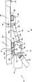
图4以放大细节图的形式示出背部支撑件、头部支撑件与驱动电机之间的齿轮传动连接的示意侧视图。Figure 4 shows a schematic side view of the geared connection between the back support, the head support and the drive motor in an enlarged detail view.
虽然本发明能做出各种修改且具有可替代构造,本发明的某些例解性实施例已在附图中示出且将在下文中详细地说明。但应了解,并没有意图将本发明限制为所公开的具体形式,而是相反,本发明涵盖属于本发明的精神和范畴内的所有修改、替代构造和等效物。While the invention is capable of various modifications and has alternative constructions, certain illustrative embodiments of the invention have been shown in the drawings and will be described in detail below. It should be understood, however, that there is no intention to limit the invention to the particular forms disclosed, but on the contrary, the invention is to cover all modifications, alternative constructions, and equivalents falling within the spirit and scope of the invention.
具体实施方式Detailed ways
图1示出本发明的可旋转的且可提升的床1处于躺睡位置的透视图,并且图2示出床1处于就坐位置或座椅位置。Figure 1 shows a perspective view of a rotatable and liftable bed 1 of the present invention in a sleeping position, and Figure 2 shows the bed 1 in a sitting or chair position.
床1以具有床边2为特征,该床边2具有头部支撑件3、脚部支撑件4以及侧壁5和6。朝向观察者的侧壁5处于躺睡位置。侧壁5以足够大的距离与地板间隔开使得在侧壁5的下边缘与地板之间存在间隙,且医务人员可将脚的前部置于床下面。侧壁5被可移动地支承且在床1的座椅位置到达向下移位的位置,如图2所示。侧壁5的专用支承件明确地在(例如)DE 199 12 987 Al中加以说明。The bed 1 is characterized by having a
提升机构8位于床边2内并且在图2中以细节形式说明。承载床垫11的床框架9借助于旋转铰链固定到提升机构8上,该旋转铰链在图中不可见。该提升机构8用来将其上带有床垫11的床框架9移动到不同高度。例如,在DE 10 2004 019 144 A1中明确地说明提升机构的设计,就这方面而言本文引用该DE 10 2004 019 144 A。The
床框架9被分成可相对于彼此移动的若干部段。各个部段的名称基本上对应于躺在床上的人的身体部位的名称。The
在图1中向上枢转的枢转头部支撑件12直接布置在头端上,其中背部支撑件13在脚端方向邻近头部支撑件。该背部支撑件13铰接到中央部段14,中央部段14继而借助于旋转铰链直接地连接到提升机构或提升机8。大腿支撑件15在中央部段14的后面并过渡为小腿支撑件16。床表面最后还带有脚部支撑件17。在旋转状态,脚部支撑件17在床中保持固定,并且仅部段12至16移动。The pivoting
床框架9构造在中间框架18上,而中间框架18继而布置在未图示的旋转铰链上,该旋转铰链将中间框架18连接到提升机构8。根据图3,中间框架18包括两个纵向侧轨,这两个纵向侧轨彼此平行地延伸,其中由于为侧视图,在图中仅可以看到这两个纵向侧轨19之一。The
中央部段包括两个纵向侧轨19,这两个纵向侧轨19布置于相对应的支架20上,该支架20固定于中间框架18的侧面上。纵向侧轨19之间的间距对应于床表面的宽度,且略微小于床垫11的宽度。The central section comprises two longitudinal side rails 19 arranged on corresponding
由两平行的侧轨21形成的中央部段14相对于中间框架18不可动。The
大腿支撑件15也包括两个平行的侧轨22,在图中也仅可看到这两个侧轨中朝向观察者的侧轨22。在投影平面中,另一侧轨位于这个侧轨后面相同的高度处。The
位于相同侧上的相应侧轨21和22借助于在床框架9两侧上的铰链23以枢接方式连接到彼此。两个铰链23的铰链轴线彼此同轴。Respective side rails 21 and 22 on the same side are pivotally connected to each other by means of
一侧轨25与床的另一侧上平行于其延伸的另一纵向侧轨25一起形成小腿支撑件16的侧向边界,所述侧轨25在每一侧借助于带有铰链轴线24的铰链而铰接到相对应的侧轨22上。One
两个侧轨25利用横撑件26连接到彼此。两个平行轨27彼此相距一定距离在中央部段14的方向从小腿支撑件16的自由端延伸。枢转杠杆布置28的辊在29处在中间框架的纵向侧轨19之间铰接到中间框架18的脚端,该枢转杠杆布置28的辊在前述轨中运行。铰链轴承29的轴线平行于铰链轴线23和24使得杠杆布置28可相应地枢转。在向上枢转运动和向下枢转运动期间,大腿支撑件15和小腿支撑件16在它们被升高或降低到根据图2的旋转位置时形成膝部弯曲,如图3所示。在这个位置,小腿支撑件16竖直向下延伸。The two
背部支撑件13铰接到中央部段14指向头端的端部。在29处图解出铰链轴线。该背部支撑件13包括两个平行的侧轨31,在图3中仅可看到这两个侧轨中在床的左侧上的侧轨,而在图2中图解了平行于该侧轨延伸的侧轨31。The
除其它构件以外,这两个侧轨31还尤其是通过构件之中的横撑件33连接到彼此,该横撑件33靠近背部支撑件13的远端。而且,它们的长度大于背部支撑件13所需要的长度。它们延伸超过可移动的头部支撑件12并且在这个区位处借助于另一横撑件34连接。The two
头部支撑件12以枢转方式支承在两个平行的侧轨31之间。其铰链或弯曲关节35在图3中示出。其(例如)是由穿过相应侧轨31而插入的螺栓形成。这个铰链关节35使得有可能将头部支撑件12从其中床垫11位于背部支撑件13的直线延伸部分中的位置移动到这个区位的升高位置,如图1和图2所示。在这个位置,床垫11相对应地在头部支撑件处略微向上成大约15°至20°角。弯曲点位于人体工程学上有利的区位处。相对于躺在床上的患者,其大约位于颈椎区域。The
提供一定数目的主轴型提升电机用于移动提升机18,从而使床框架9从根据图1的床位置旋转到根据图2的座椅位置以及移动大腿支撑件15和小腿支撑件16,其中这些提升电机并未详细地图解,因为这对于理解本发明而言不是必需的。由中央微处理器控制装置来启动主轴型提升电机,该中央微处理器控制装置从手动控制器接收输入信号。A number of spindle-type lift motors are provided for moving the
背部支撑件13也借助于主轴型提升电机来移动,其中仅可以看到刚性引导管36和可移动且可伸缩地延伸的提升管37。电机的枢转联接点被覆盖。The
在图4中以放大细节的形式示出提升管37与背部支撑件13以及头部支撑件12之间的运动学连接。The kinematic connection between the
图4示出致动机构43的放大细节,致动机构43被设计成用于实现头部支撑件12和背部支撑件13的顺序运动。枢转的中间杠杆44和联接杆45形成致动机构43的部分。FIG. 4 shows an enlarged detail of the
在图中可以看到位于床右侧的中间框架18的纵向侧轨19。为了暴露致动装置43,省略了在床左侧上平行于该右侧的纵向侧轨19而延伸的纵向侧轨19。The longitudinal side rails 19 of the
中间杠杆44以枢转方式支承于连接撑件或横撑件33上。根据该图,撑件33邻近铰链轴线35且在中央部段15的方向上偏移短小距离。指向中央部段14方向的两个耳状物47距彼此一定距离而被大约居中地焊接到横撑件33上。中间杠杆44被支承在这些耳状物之间处于插入于其内的圆柱形螺栓48上。The
中间杠杆44具有近似矩形板的形状,其在49处具有矩形凹口。该凹口49形成直的阻挡面50,该阻挡面50与矩形截面的横撑件33的底侧协作,以便限制该中间杠杆44相对于该图例在逆时针方向上的枢转运动。The
中间杠杆44包含总共三个孔51、52和53用于实现各个铰链。延伸穿过孔53的套管54例如被焊接到中间杠杆44上。该套管54的长度对应于刚性耳状物47之间的距离。该套管54用来以非倾斜方式在插入螺栓48上支承中间杠杆54。这确保了中间杠杆44可仅执行绕螺栓48的轴线并因此平行于床框架9的其它铰链轴线的运动。The
其叉端与中间杠杆44重叠的叉头56被拧入到螺旋主轴电机的提升管37内。圆柱形铰链销57延伸穿过对准的孔,并因此在叉头56与枢转杠杆44之间产生铰链状连接。A
借助于联接杆45,中间杠杆44的枢转运动被传输到头部支撑件12。在图中可以看到头部支撑件12的左纵向侧轨39,且其类似于另一纵向侧轨以L轮廓形式实现。两个纵向侧轨39借助于横撑件58连接到彼此。横撑件58位于铰链销35附近。指向枢转或中间杠杆44方向的耳状物59固定于横撑件58上。其具备横向孔,圆柱形螺栓61插入到该横向孔内以在耳状物59与联接杆45之间形成连接。The pivoting movement of the
联接杆45包括两个叠合的部分撑件62和63,其距彼此一定距离延伸且借助于若干个间隔件64分别根据枢转杠杆44或耳状物59的厚度被间隔开。所述两个部分撑件62和63借助于延伸穿过该部分撑件的铆钉65而刚性地连接到彼此。The
联接杆45还包含在两个部分撑件62和63中在枢转杠杆44附近的相对应的通孔。圆柱形销66延伸穿过这些孔,以及穿过孔51,该圆柱形销66形成铰链用于在联接杆45与中间杠杆44之间产生枢接式连接。The
联接杆45作用于头部支撑件12上所凭借的有效半径大约精确地与孔53与孔52之间的距离一样大。实现该布置使得枢转或中间杠杆44大约在与头部支承件12相同的角度范围上行进。The effective radius with which the
为了防止头部支撑件12下落,阻挡件67布置于纵向侧轨31的远端,其中当床表面应为完全平坦时头部支撑件的纵向侧轨39抵靠着这些阻挡件。In order to prevent the
床功能的说明如下:The description of the bed function is as follows:
在躺睡位置,负责背部支撑件13的螺旋主轴驱动器完全缩回,即,提升管37缩回到使得头部支撑件12能够容许其两个纵向侧轨39抵靠着阻挡件67的程度。为了简化调整,相对应的螺旋主轴驱动器优选地以分离式驱动器(decoupled drive)的形式来实现,即,使得仅压缩力可施加于提升管37上。因此电机自身可返回到实际上任何端位置而不会在致动装置43中造成应力。In the sleeping position, the screw spindle drive responsible for the
在降低位置,背部支撑件13也容许其横撑件33抵靠着中间框架18的纵向侧轨19的上侧。In the lowered position, the
孔53和52的轴线所在的连接平面相对于与降低的背部支撑件13正交的线以大约15°的角延伸。The connection plane in which the axes of the
如果在这个位置启动相对应的主轴型提升电机以便延伸以相对于背部支撑件12的平面成大约30°锐角而接合的提升管37,中间杠杆44最初在参考图4说明的逆时针方向上枢转。该中间杠杆44的该枢转运动借助于联接杆45传输到头部支撑件12的耳状物59。与中间杠杆44的枢转运动或提升管37的延伸相一致地,头部支撑件12分别从平躺位置升高。所述提升管37的延伸控制头部支撑件12应被升高的程度。一旦使用者到达舒适的头部位置,可通过释放相应控制键来停止主轴型提升电机以结束提升管37的提升运动。因此躺在床上的人可调整舒适的头部位置,例如为了在床的躺睡位置躺睡。使用者无需协助即可调整头部的提升。If the corresponding spindle-type lift motor is activated in this position to extend the
如果主轴型提升电机保持被启动足够长的时间,那么该提升管37延伸直至中间杠杆44的阻挡面50接触横撑件33的底侧。这表示已达到中间杠杆44相对于背部支撑件12的纵向侧轨31的最大枢转角。这种枢转运动对应于升高头部支撑件大约15°至不超过20°,其中20°可能已经有些过大。If the spindle type lift motor remains activated long enough, the
在头部支撑件12被提高到其最大限度之后,即直到使用者再次停止相对应的驱动器,与提升管37的进一步延伸相关联的相应驱动器的另一致动此刻也造成背部支撑件13升高。After the
在对背部支撑件13进行任何调整时,头部支撑件12相对于背部支撑件13保持在相应最大角。图2和图3示出具有背部支撑件13的不同倾斜角的中间位置。During any adjustment of the
如果相对应的驱动器是在相反方向上被致动,提升管37再次缩回。这最初造成背部支撑件13降低直到其返回到水平位置。在水平位置,由于横撑件33与中间框架18的侧轨19之间的刚性相互作用(positiveinteraction)防止了额外的向下移动。中间杠杆44仅在到达这个位置之后才开始相对于背部支撑件13枢转且中间杠杆44不再需要传输力到撑件33。这个枢转运动表示头部支撑件12也被降低。If the corresponding drive is actuated in the opposite direction, the
使用者能将头部支撑件12移动到人体工程学舒适的位置而无需协助,也无需利用另一电驱动器。实际经验示出在任何就坐位置总是需要头部支撑件12升高到最大升高位置,其中背部支撑件13被升高到更大或更小的程度。The user is able to move the
头部支撑件的自动驱动也确保了正确的顺序并排除了床的中央控制器中的额外控制技术支出。The automatic drive of the head support also ensures the correct sequence and eliminates the expenditure of additional control technology in the central controller of the bed.
应当很清楚的是,由阻挡面50和横撑件33所形成的枢转阻挡件也可刚好容纳于头部支撑件12的纵向侧轨39的区域中。可以看出所述布置的优点在于,若需要时可通过使联接杆45脱离来停止头部支撑件的运动,即无需对背部支撑件的其余驱动器做任何其它修改。因此,在特殊疾病需要这样做的情况下,医务人员可容易地将床重设为另一操作模式。It should be clear that the pivotal stop formed by the blocking
医院用床以具有床框架为特征,床框架具备可移动的背部支撑件和可移动的头部支撑件。齿轮机构确保了可借助于单个电机来移动头部支撑件和背部支撑件。在头部支撑件到达最大升高位置后,自动地开始背部支撑件的提升。Hospital beds are characterized by having a bed frame with a movable back support and a movable head support. A gear mechanism ensures that the head support and the back support can be moved by means of a single motor. Lifting of the back support starts automatically after the head support has reached the maximum raised position.
Claims (21)
Applications Claiming Priority (3)
| Application Number | Priority Date | Filing Date | Title |
|---|---|---|---|
| DE102006052699ADE102006052699B4 (en) | 2006-11-07 | 2006-11-07 | Care bed with adjustable headboard |
| DE102006052699.6 | 2006-11-07 | ||
| PCT/EP2007/008845WO2008055573A1 (en) | 2006-11-07 | 2007-10-11 | Hospital bed having an adjustable head rest |
Publications (2)
| Publication Number | Publication Date |
|---|---|
| CN101563055Atrue CN101563055A (en) | 2009-10-21 |
| CN101563055B CN101563055B (en) | 2012-02-01 |
Family
ID=38973070
Family Applications (1)
| Application Number | Title | Priority Date | Filing Date |
|---|---|---|---|
| CN2007800414645AExpired - Fee RelatedCN101563055B (en) | 2006-11-07 | 2007-10-11 | Hospital bed with adjustable head support |
Country Status (9)
| Country | Link |
|---|---|
| US (1) | US20100071132A1 (en) |
| EP (1) | EP2086488B1 (en) |
| JP (1) | JP2010508101A (en) |
| CN (1) | CN101563055B (en) |
| AT (1) | ATE481075T1 (en) |
| DE (2) | DE102006052699B4 (en) |
| DK (1) | DK2086488T3 (en) |
| PL (1) | PL2086488T3 (en) |
| WO (1) | WO2008055573A1 (en) |
Cited By (2)
| Publication number | Priority date | Publication date | Assignee | Title |
|---|---|---|---|---|
| CN106880213A (en)* | 2015-11-24 | 2017-06-23 | 安得士股份有限公司 | Bed |
| CN107736969A (en)* | 2012-08-18 | 2018-02-27 | 有限会社知财经营社 | Sleeping posture controls bed system |
Families Citing this family (8)
| Publication number | Priority date | Publication date | Assignee | Title |
|---|---|---|---|---|
| DE102004019144B3 (en)* | 2004-04-21 | 2005-09-22 | Barthelt, Hans-Peter, Dipl.-Ing. | Nursing bed with improved lift |
| DE102011078644A1 (en)* | 2011-07-05 | 2013-01-10 | Werner Helmert | mattress |
| JP5831972B2 (en)* | 2011-10-03 | 2015-12-16 | パラマウントベッド株式会社 | Manual power generator for actuator driving and actuator driving device |
| KR200475591Y1 (en)* | 2014-03-31 | 2014-12-12 | 장경원 | complex exercise equipment for pilates |
| JP2018175386A (en)* | 2017-04-12 | 2018-11-15 | 日建リース工業株式会社 | Care bed and head raising attachment |
| DE102017115031A1 (en)* | 2017-07-05 | 2019-01-10 | Hans-Joachim Kleeberg | care bed |
| TWM553151U (en)* | 2017-07-24 | 2017-12-21 | Quan Hang Shi | Electric bed |
| CN113475901A (en)* | 2021-08-10 | 2021-10-08 | 山东爱必居家居有限公司 | Multi-gear adjustable backrest solid wood soft packing bed |
Family Cites Families (15)
| Publication number | Priority date | Publication date | Assignee | Title |
|---|---|---|---|---|
| CH682124A5 (en)* | 1991-04-24 | 1993-07-30 | Lanz Ind Technik Ag | Item of furniture on which to lie - has base frame and at least one part of slat grid movable by drive |
| DE29602931U1 (en)* | 1996-02-20 | 1996-07-11 | OPTIMO Möbelhandelsgesellschaft mbH, 84359 Simbach | Adjustable fitting for slatted frames |
| JP3841128B2 (en)* | 1997-09-05 | 2006-11-01 | 京和装備株式会社 | Floatable bed with floorboard |
| DE19912937C2 (en)* | 1999-03-22 | 2001-09-20 | Kleeberg Hans Joachim | Bed with lowerable side part |
| ES2267603T3 (en)* | 1999-12-23 | 2007-03-16 | Cimosys Ag | ADJUSTABLE SUPPORT DEVICE FOR THE PADDING OF A FURNITURE OF SEAT AND / OR BED. |
| DE19962541C3 (en)* | 1999-12-23 | 2003-11-27 | Ag Goldingen Cimosys | Motor-adjustable support device for upholstering a seating and / or reclining furniture, for example a mattress or a bed |
| DE20006690U1 (en)* | 2000-04-11 | 2001-08-16 | Cimosys Ag, Goldingen | Furniture drive designed as a double drive |
| FR2814352B1 (en)* | 2000-09-26 | 2002-11-29 | Creations Andre Renault | SUMMER WITH BACKREST AND ARTICULATED HEADER AND LIFTING HEADER OF A NEW TYPE |
| DE20211071U1 (en)* | 2002-07-22 | 2003-12-11 | Dewert Antriebs- Und Systemtechnik Gmbh & Co Kg | Lying unit |
| DE10250075A1 (en)* | 2002-10-25 | 2004-05-13 | Hans-Peter Barthelt | Swivel bed with improved swivel hinge |
| US7036165B2 (en)* | 2003-04-02 | 2006-05-02 | L&P Property Management Company | Adjustable bed with automatic adjusting head section |
| DE10330759B4 (en)* | 2003-07-07 | 2010-04-15 | Hans-Peter Barthelt | Revolving and standing bed with thigh lift |
| JP2005230377A (en)* | 2004-02-23 | 2005-09-02 | Amami:Kk | Tumble bed |
| DE102004019144B3 (en)* | 2004-04-21 | 2005-09-22 | Barthelt, Hans-Peter, Dipl.-Ing. | Nursing bed with improved lift |
| JP2005312649A (en)* | 2004-04-28 | 2005-11-10 | Atex:Kk | Mattress body and bed using the same |
- 2006
- 2006-11-07DEDE102006052699Apatent/DE102006052699B4/ennot_activeExpired - Fee Related
- 2007
- 2007-10-11WOPCT/EP2007/008845patent/WO2008055573A1/enactiveApplication Filing
- 2007-10-11EPEP07818916Apatent/EP2086488B1/ennot_activeNot-in-force
- 2007-10-11JPJP2009535001Apatent/JP2010508101A/enactivePending
- 2007-10-11DKDK07818916.4Tpatent/DK2086488T3/enactive
- 2007-10-11PLPL07818916Tpatent/PL2086488T3/enunknown
- 2007-10-11CNCN2007800414645Apatent/CN101563055B/ennot_activeExpired - Fee Related
- 2007-10-11ATAT07818916Tpatent/ATE481075T1/enactive
- 2007-10-11USUS12/513,605patent/US20100071132A1/ennot_activeAbandoned
- 2007-10-11DEDE502007005088Tpatent/DE502007005088D1/enactiveActive
Cited By (2)
| Publication number | Priority date | Publication date | Assignee | Title |
|---|---|---|---|---|
| CN107736969A (en)* | 2012-08-18 | 2018-02-27 | 有限会社知财经营社 | Sleeping posture controls bed system |
| CN106880213A (en)* | 2015-11-24 | 2017-06-23 | 安得士股份有限公司 | Bed |
Also Published As
| Publication number | Publication date |
|---|---|
| EP2086488B1 (en) | 2010-09-15 |
| DE502007005088D1 (en) | 2010-10-28 |
| EP2086488A1 (en) | 2009-08-12 |
| US20100071132A1 (en) | 2010-03-25 |
| ATE481075T1 (en) | 2010-10-15 |
| PL2086488T3 (en) | 2011-04-29 |
| WO2008055573A1 (en) | 2008-05-15 |
| DK2086488T3 (en) | 2011-01-24 |
| DE102006052699B4 (en) | 2008-10-02 |
| CN101563055B (en) | 2012-02-01 |
| JP2010508101A (en) | 2010-03-18 |
| WO2008055573A8 (en) | 2009-05-28 |
| DE102006052699A1 (en) | 2008-05-08 |
Similar Documents
| Publication | Publication Date | Title |
|---|---|---|
| CN101563055A (en) | Hospital bed with adjustable head support | |
| US8474075B2 (en) | Bed | |
| US7055195B2 (en) | Patient bed with CPR system | |
| CN100515378C (en) | Rotating bed with improved rotating hinge | |
| EP2361595A2 (en) | Height adjustable bed with a push chain assembly | |
| CN1816314A (en) | Swivel and Get Up Bed with Thigh Lift | |
| EP1350449A1 (en) | Adjustable profiling beds | |
| CN1612721A (en) | Rotating bed for increased stability | |
| WO2007149413A2 (en) | Canister lift for a patient support apparatus | |
| US11471346B2 (en) | Long term care bed | |
| CN110812036A (en) | Liftable rotatory medical bed | |
| CN204484565U (en) | Monitoring sick bed backboard lifting structure | |
| CN1946360B (en) | Bed | |
| US7451505B2 (en) | Bed tilting apparatus | |
| JP4965946B2 (en) | bed | |
| CN219022007U (en) | Nursing bed with play back of body safeguard function | |
| CN108175584B (en) | Automatic driving device for toilet | |
| EP3833314B1 (en) | Bed with actuatable mattress support platform and method of actuating such a bed | |
| JP2014217690A (en) | Electric full-reclining chair | |
| CN115105339A (en) | A kind of nursing bed for multiple trauma cricothyroid membrane puncture used in emergency intensive care unit | |
| CN221410854U (en) | Lifting bed | |
| EP2873399B1 (en) | Person support apparatus | |
| CN219000945U (en) | Nursing bed with function of lifting back and sliding back | |
| CN210673595U (en) | Wheelchair bed with back capable of being stably lifted and lowered | |
| US20230107717A1 (en) | Patient support apparatus with a hydraulic lift having powered and manual modes |
Legal Events
| Date | Code | Title | Description |
|---|---|---|---|
| C06 | Publication | ||
| PB01 | Publication | ||
| C10 | Entry into substantive examination | ||
| SE01 | Entry into force of request for substantive examination | ||
| C14 | Grant of patent or utility model | ||
| GR01 | Patent grant | ||
| C17 | Cessation of patent right | ||
| CF01 | Termination of patent right due to non-payment of annual fee | Granted publication date:20120201 Termination date:20121011 |