CN101561119B - Backlight unit and liquid crystal display module including the same - Google Patents
Backlight unit and liquid crystal display module including the sameDownload PDFInfo
- Publication number
- CN101561119B CN101561119BCN2008101846820ACN200810184682ACN101561119BCN 101561119 BCN101561119 BCN 101561119BCN 2008101846820 ACN2008101846820 ACN 2008101846820ACN 200810184682 ACN200810184682 ACN 200810184682ACN 101561119 BCN101561119 BCN 101561119B
- Authority
- CN
- China
- Prior art keywords
- diffusion plate
- backlight unit
- distance
- pattern
- lamp
- Prior art date
- Legal status (The legal status is an assumption and is not a legal conclusion. Google has not performed a legal analysis and makes no representation as to the accuracy of the status listed.)
- Active
Links
Images


Classifications
- G—PHYSICS
- G02—OPTICS
- G02F—OPTICAL DEVICES OR ARRANGEMENTS FOR THE CONTROL OF LIGHT BY MODIFICATION OF THE OPTICAL PROPERTIES OF THE MEDIA OF THE ELEMENTS INVOLVED THEREIN; NON-LINEAR OPTICS; FREQUENCY-CHANGING OF LIGHT; OPTICAL LOGIC ELEMENTS; OPTICAL ANALOGUE/DIGITAL CONVERTERS
- G02F1/00—Devices or arrangements for the control of the intensity, colour, phase, polarisation or direction of light arriving from an independent light source, e.g. switching, gating or modulating; Non-linear optics
- G02F1/01—Devices or arrangements for the control of the intensity, colour, phase, polarisation or direction of light arriving from an independent light source, e.g. switching, gating or modulating; Non-linear optics for the control of the intensity, phase, polarisation or colour
- G02F1/13—Devices or arrangements for the control of the intensity, colour, phase, polarisation or direction of light arriving from an independent light source, e.g. switching, gating or modulating; Non-linear optics for the control of the intensity, phase, polarisation or colour based on liquid crystals, e.g. single liquid crystal display cells
- G02F1/133—Constructional arrangements; Operation of liquid crystal cells; Circuit arrangements
- G02F1/1333—Constructional arrangements; Manufacturing methods
- G02F1/1335—Structural association of cells with optical devices, e.g. polarisers or reflectors
- G02F1/1336—Illuminating devices
- G02F1/133602—Direct backlight
- G02F1/133606—Direct backlight including a specially adapted diffusing, scattering or light controlling members
- G—PHYSICS
- G02—OPTICS
- G02F—OPTICAL DEVICES OR ARRANGEMENTS FOR THE CONTROL OF LIGHT BY MODIFICATION OF THE OPTICAL PROPERTIES OF THE MEDIA OF THE ELEMENTS INVOLVED THEREIN; NON-LINEAR OPTICS; FREQUENCY-CHANGING OF LIGHT; OPTICAL LOGIC ELEMENTS; OPTICAL ANALOGUE/DIGITAL CONVERTERS
- G02F1/00—Devices or arrangements for the control of the intensity, colour, phase, polarisation or direction of light arriving from an independent light source, e.g. switching, gating or modulating; Non-linear optics
- G02F1/01—Devices or arrangements for the control of the intensity, colour, phase, polarisation or direction of light arriving from an independent light source, e.g. switching, gating or modulating; Non-linear optics for the control of the intensity, phase, polarisation or colour
- G02F1/13—Devices or arrangements for the control of the intensity, colour, phase, polarisation or direction of light arriving from an independent light source, e.g. switching, gating or modulating; Non-linear optics for the control of the intensity, phase, polarisation or colour based on liquid crystals, e.g. single liquid crystal display cells
- G02F1/133—Constructional arrangements; Operation of liquid crystal cells; Circuit arrangements
- G02F1/1333—Constructional arrangements; Manufacturing methods
- G02F1/1335—Structural association of cells with optical devices, e.g. polarisers or reflectors
- G02F1/1336—Illuminating devices
- G02F1/133602—Direct backlight
- G02F1/133606—Direct backlight including a specially adapted diffusing, scattering or light controlling members
- G02F1/133607—Direct backlight including a specially adapted diffusing, scattering or light controlling members the light controlling member including light directing or refracting elements, e.g. prisms or lenses
Landscapes
- Physics & Mathematics (AREA)
- Nonlinear Science (AREA)
- Mathematical Physics (AREA)
- Chemical & Material Sciences (AREA)
- Crystallography & Structural Chemistry (AREA)
- General Physics & Mathematics (AREA)
- Optics & Photonics (AREA)
- Liquid Crystal (AREA)
- Planar Illumination Modules (AREA)
Abstract
Translated fromChineseDescription
Translated fromChinese技术领域technical field
本发明涉及液晶显示(LCD)装置,更具体地说,涉及背光单元和包括该背光单元的液晶显示装置。The present invention relates to a liquid crystal display (LCD) device, and more particularly, to a backlight unit and a liquid crystal display device including the same.
背景技术Background technique
本申请要求2008年4月16日提交的韩国专利申请10-2008-0035057的优选权,此处以引证的方式并入其全部内容,就像在此进行了完整阐述一样。This application claims priority to Korean Patent Application No. 10-2008-0035057 filed April 16, 2008, which is hereby incorporated by reference in its entirety as if fully set forth herein.
近来,具有厚度薄、重量轻和低功耗的优点的各种平板显示器(FPD)已经被开发出来并取代了阴极射线管(CRT)。FPD装置包括等离子显示面板(PDP)、液晶显示(LCD)装置、电致发光显示(ELD)装置等。Recently, various flat panel displays (FPDs) having advantages of thin thickness, light weight, and low power consumption have been developed to replace cathode ray tubes (CRTs). FPD devices include plasma display panels (PDPs), liquid crystal display (LCD) devices, electroluminescence display (ELD) devices, and the like.
PDP通过使从上基板和下基板之间包含的气体(例如,氙气(Xe)和氖气(Ne))发出的紫外线与荧光材料碰撞并发出可见光线(即,通过由于气体放电产生的紫外线导致的荧光材料发光)来显示图像。LCD装置通过根据电场来控制从背光单元发出并透过像素的光的透射率而显示图像,该电场在上基板和下基板之间插入的液晶层中感生出并通过像素的信号电压进行改变。ELD装置通过在阳极和阴极之间插入有机发光材料并通过电流使有机分子发光来显示图像。PDPs emit visible rays by causing ultraviolet rays emitted from gases contained between the upper and lower substrates (for example, xenon gas (Xe) and neon gas (Ne)) to collide with fluorescent materials and emit visible rays (that is, caused by ultraviolet rays due to gas discharge. The fluorescent material emits light) to display the image. The LCD device displays images by controlling transmittance of light emitted from a backlight unit and transmitted through pixels according to an electric field induced in a liquid crystal layer interposed between upper and lower substrates and changed by a signal voltage of the pixels. The ELD device displays images by interposing an organic light-emitting material between an anode and a cathode and passing an electric current to make organic molecules emit light.
在这些显示装置中,LCD装置因能够出色地显示运动图像并具有较高的对比度而得到广泛应用。Among these display devices, LCD devices are widely used because they can display moving images excellently and have a high contrast ratio.
通常,LCD装置利用了液晶分子的光学各向异性和偏振特性。液晶分子由于其细长形状而具有确切的取向方向。可以通过在液晶分子上施加电场来控制液晶分子的取向方向。换句话说,随着电场的强度或方向的改变,液晶分子的取向也发生变化。因为入射光由于液晶分子的光学各向异性基于液晶分子的朝向而被折射,所以可以通过控制光透射率来显示图像。In general, LCD devices utilize optical anisotropy and polarization properties of liquid crystal molecules. Liquid crystal molecules have a definite alignment direction due to their elongated shape. The alignment direction of the liquid crystal molecules can be controlled by applying an electric field on the liquid crystal molecules. In other words, as the strength or direction of the electric field changes, the orientation of the liquid crystal molecules also changes. Since incident light is refracted based on the orientation of the liquid crystal molecules due to the optical anisotropy of the liquid crystal molecules, an image can be displayed by controlling light transmittance.
LCD装置不是自发光装置并且需要附加光源。通过在液晶面板的背面设置背光单元以向液晶面板发射光,来显示可辨别的图像。LCD devices are not self-emitting devices and require an additional light source. Recognizable images are displayed by providing a backlight unit on the back of the liquid crystal panel to emit light to the liquid crystal panel.
根据光源相对于显示面板的位置,背光单元被分类为边缘型(edge-type)或直下型(direct-type)。在边缘型背光单元(可以称为侧光型)中,在背光单元的导光板的一侧或两侧分别设置了一个灯或者一对灯。边缘型背光单元具有容易制造的优点。在直下型背光单元中,多个灯被直接设置在散射板的下方,并向液晶面板提供光。由于直下型背光单元具有较高的光均匀性,因此其广泛应用于大尺寸LCD装置。Backlight units are classified as edge-type or direct-type according to the position of the light source relative to the display panel. In an edge-type backlight unit (may be referred to as an edge-light type), one lamp or a pair of lamps are provided on one side or both sides of a light guide plate of the backlight unit, respectively. The edge type backlight unit has the advantage of being easy to manufacture. In the direct type backlight unit, a plurality of lamps are disposed directly under the diffusion plate and provide light to the liquid crystal panel. Since the direct type backlight unit has high light uniformity, it is widely used in large-sized LCD devices.
近来,20英寸以上的大尺寸显示装置受到高度欢迎,并且考虑到该装置的亮度和对比度,因为直下型背光单元由于多个灯而具有较高的光效率且在尺寸上没有限制,所以将直下型背光单元应用于大尺寸显示装置。Recently, large-sized display devices of 20 inches or more are highly popular, and considering the brightness and contrast of the device, since the direct-type backlight unit has high light efficiency due to multiple lamps and there is no limit in size, the direct-down The type backlight unit is applied to a large-sized display device.
同时,利用各种机械元件将液晶面板和背光单元组装成模块以保护它们免遭外部冲击、防止光泄漏,并且可以将该模块称为液晶显示模块。Meanwhile, the liquid crystal panel and the backlight unit are assembled into a module using various mechanical elements to protect them from external impact, prevent light leakage, and the module may be called a liquid crystal display module.
图1是例示根据相关技术的包括直下型背光单元的液晶显示模块的分解立体图。在图1中,相关技术的LCD模块1包括液晶面板10、背光单元20、支撑主体30、顶壳40以及底盖50。FIG. 1 is an exploded perspective view illustrating a liquid crystal display module including a direct type backlight unit according to the related art. In FIG. 1 , a related art LCD module 1 includes a
液晶面板10包括上基板和下基板(未示出)以及上基板与下基板之间的液晶层(未示出)。在下基板上形成薄膜晶体管(未示出),并且在上基板上形成滤色器(未示出)。根据薄膜晶体管的导通/截止状态来显示图像。此外,选通和数据印刷电路板15连接到液晶面板10并分别向液晶面板10提供扫描信号和数据信号。The
直下型背光单元20设置在液晶面板10的背表面,并向液晶面板10提供光。背光单元20包括彼此隔开的多个灯24。反射片22设置在该多个灯24的下方。一对支撑边33与各灯24的对应边结合以支撑多个灯24。将散射板25和多个光学片26设置在多个灯24上方。散射板25中包括多个珠子。The direct
在支撑主体30上设置液晶面板10和背光单元20。支撑主体30防止液晶面板10和背光单元20移动并支撑液晶面板10和背光单元20。The
顶壳40覆盖液晶面板10的上表面的边缘和支撑主体30的侧表面以支撑和保护晶面板10的边缘和支撑主体30的侧表面。The
底盖50覆盖支撑主体30的下表面并保护LCD模块1的下部元件。底盖50通过连接单元(未示出)与支撑主体30和顶壳40结合以形成模块。The
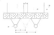
图2是放大了包括根据相关技术的直下型背光单元的LCD模块的一部分的剖视图。图3是例示了根据相关技术的直下型背光单元的散射板的剖视图。FIG. 2 is an enlarged cross-sectional view of a part of an LCD module including a direct type backlight unit according to the related art. 3 is a cross-sectional view illustrating a diffusion plate of a direct type backlight unit according to the related art.
在图2中,相关技术的LCD模块的直下型背光单元20包括反射片22、多个灯24、散射板25和多个光学片26。在底盖50上设置反射片22。多个灯24设置在反射片122的上方,并且以第一距离S彼此隔开。散射板25以相对于底盖50的上表面(更具体地说,与反射片22)相隔第二距离D设置在多个灯24上方。参照图3,散射板25具有平坦的上表面和下表面,并包括球形形状并随机分布的多个珠子27。因此,当来自多个灯24的光入射到散射板25上时,珠子27改变了光的路径,从而光发生散射。In FIG. 2 , a direct
然而,即使使用散射板25,如果相邻灯24之间的距离增大到超过了散射板25的散射能力,在与灯24对应的第一区域A和与相邻灯24之间的部分对应的第二区域B之间也会存在亮度差。该亮度差在显示的图像上导致云纹(mura)缺陷。为防止这种情况,以预定距离S设置该多个灯24,并使散射板25相对于反射片22相隔预定第二距离D地设置在灯22上方,由此使光散射并均匀化亮度分布。此时,相邻灯24之间的第一距离S与反射片22和散射板25之间的第二距离D之比(即,第一距离S比第二距离D的值(其可以称为距离比S/D))对于防止由于亮度差造成的云纹缺陷是非常重要的因素。However, even if the
通常,在如上所述包括随机分散的多个珠子27的一个散射板25设置在相邻灯24上方的情况下,如果散射板25和灯24被设置成使得距离比S/D等于或者小于1.35,则不存在由于亮度差而造成的云纹缺陷。Generally, in the case where one
然而,在相关技术的LCD模块中,当灯24和散射板25设置成使得距离比S/D在1.35到2.75的范围内时,则存在如图4所示由于亮度差造成的周期性呈现的线状暗部的云纹缺陷。图4是示出了包括灯和散射板的相关技术的LCD模块中显示的白色图像(white image),该灯和散射板被设置为距离比S/D在1.35到2.75的范围内。However, in the LCD module of the related art, when the
图5为例示了根据相关技术的另一实施方式的LCD模块的一部分的图,并示出了散射板和灯。图6是示出了来自灯的透过散射板的光的状态的图。这里,与图2相比,加宽了相邻灯之间的距离。FIG. 5 is a diagram illustrating a part of an LCD module according to another embodiment of the related art, and shows a diffusion plate and lamps. Fig. 6 is a diagram showing a state of light from a lamp transmitted through a diffusion plate. Here, compared with FIG. 2, the distance between adjacent lamps is widened.
在图5和图6中,为缩减制造成本,减少了灯24的数量,并将相邻灯之间的第一距离增大为2S。图5中的第一距离是图2中第一距离S的两倍。此时,从灯24发出的光到达散射板25具有不同的路径,并且存在由于路径差而使亮度迅速降低的区域C。因此,这产生了亮度差,并且因为该路径差超出了散射板25的散射能力而出现了云纹缺陷。In FIG. 5 and FIG. 6 , in order to reduce the manufacturing cost, the number of
同时,如果减小底盖50的厚度或高度以便制造薄型装置,则减小了反射片22和散射板25之间的第二距离D。因此,距离比大于1.35,因而出现了云纹缺陷。Meanwhile, if the thickness or height of the
发明内容Contents of the invention
因此,本发明致力于一种背光单元和包括该背光单元的液晶显示模块,其基本上消除了由于相关技术的限制和缺点而造成的一个或更多个问题。Accordingly, the present invention is directed to a backlight unit and a liquid crystal display module including the same that substantially obviate one or more problems due to limitations and disadvantages of the related art.
本发明的一个优点是,提供了一种背光单元和包括该背光单元的液晶显示模块,其防止了云纹缺陷并具有均匀亮度以显示改善的图像。An advantage of the present invention is to provide a backlight unit and a liquid crystal display module including the same, which prevent moiré defects and have uniform brightness to display improved images.
本发明的其他目的和优点将部分在下述描述中阐述,部分根据该描述显而易见或者可以通过本发明的实践获知。本发明的这些和其他优点可以通过书面描述及其所附权利要求以及附图中具体指出的结构实现和获得。Additional objects and advantages of the invention will be set forth in part in the description which follows, and in part will be obvious from the description, or may be learned by practice of the invention. These and other advantages of the invention may be realized and attained by the structure particularly pointed out in the written description and claims hereof as well as the appended drawings.
为实现这些和其他优点,并根据本发明的实施方式的目的,如具体实施和宽泛描述的,背光单元包括:反射片;设置在该反射片上方的灯,并且相邻灯之间具有第一距离;第一散射板,其设置在灯的上方,并且以第二距离与反射片间隔开,第一散射板具有面向该反射片的第一表面和与该第一表面相反的第二表面;其中,第一表面是平坦的,并且第二表面包括第一图案;以及第二散射板,其设置在第一散射板上方,该第二散射板具有面向第一散射板的第三表面和与该第三表面相反的第四表面,其中,第三表面是平坦的,并且所述第四表面包括第二图案;其中,第一距离与所述第二距离之比在大于0且小于或等于2.75的范围内。To achieve these and other advantages, and in accordance with the purpose of embodiments of the present invention, as embodied and broadly described, a backlight unit includes: a reflective sheet; lamps disposed above the reflective sheet with first Distance; the first diffuser plate, which is arranged above the lamp and is spaced apart from the reflective sheet by a second distance, the first diffuser plate has a first surface facing the reflective sheet and a second surface opposite to the first surface; Wherein, the first surface is flat, and the second surface includes the first pattern; and the second diffusion plate is arranged above the first diffusion plate, and the second diffusion plate has a third surface facing the first diffusion plate and A fourth surface opposite to the third surface, wherein the third surface is flat, and the fourth surface includes a second pattern; wherein the ratio of the first distance to the second distance is greater than 0 and less than or equal to 2.75 range.
另一方面,液晶显示装置包括:背光单元,该背光单元包括:反射片;设置在该反射片上方的灯,并且相邻灯之间具有第一距离;第一散射板,其设置在灯的上方,并且以第二距离与反射片间隔开,第一散射板具有面向该反射片的第一表面和与该第一表面相反的第二表面;其中,第一表面是平坦的,并且第二表面包括第一图案;以及第二散射板,其设置在第一散射板上方,该第二散射板具有面向第一散射板的第三表面和与该第三表面相反的第四表面,其中,第三表面是平坦的,并且所述第四表面包括第二图案;位于该背光单元上方的液晶面板;位于该液晶面板下方且位于该背光单元上方的支撑主体;以及顶壳,其覆盖该液晶面板的上表面的边缘和该支撑主体的侧表面,其中,第一距离与第二距离之比在大于0且小于或等于2.75的范围内。On the other hand, the liquid crystal display device includes: a backlight unit, and the backlight unit includes: a reflective sheet; a lamp arranged above the reflective sheet, and there is a first distance between adjacent lamps; a first diffusion plate, which is arranged on the lamp above, and spaced apart from the reflection sheet by a second distance, the first diffusion plate has a first surface facing the reflection sheet and a second surface opposite to the first surface; wherein the first surface is flat, and the second The surface includes a first pattern; and a second diffusion plate disposed above the first diffusion plate, the second diffusion plate has a third surface facing the first diffusion plate and a fourth surface opposite to the third surface, wherein, The third surface is flat, and the fourth surface includes a second pattern; a liquid crystal panel located above the backlight unit; a supporting body located below the liquid crystal panel and above the backlight unit; and a top case covering the liquid crystal The edge of the upper surface of the panel and the side surface of the supporting body, wherein the ratio of the first distance to the second distance is within a range greater than 0 and less than or equal to 2.75.
应当理解,前面的一般性描述和后面的详细描述是示例性和解释性的,并且旨在对要保护的本发明提供进一步的解释。It is to be understood that both the foregoing general description and the following detailed description are exemplary and explanatory and are intended to provide further explanation of the invention as claimed.
附图说明Description of drawings
附图被包括进来以提供对本发明的进一步理解,并结合到本说明书中且构成本说明书的一部分,附图示出了本发明的实施方式,且与说明书一起用于解释本发明的原理。The accompanying drawings, which are included to provide a further understanding of the invention and are incorporated in and constitute a part of this specification, illustrate embodiments of the invention and together with the description serve to explain the principle of the invention.
附图中:In the attached picture:
图1是例示根据相关技术的包括直下型背光单元的液晶显示(LCD)模块的分解立体图;1 is an exploded perspective view illustrating a liquid crystal display (LCD) module including a direct type backlight unit according to the related art;
图2是放大了包括根据相关技术的直下型背光单元的LCD模块的一部分的剖视图;2 is a cross-sectional view enlarging a part of an LCD module including a direct type backlight unit according to the related art;
图3是例示根据相关技术的直下型背光单元的散射板的剖视图;3 is a cross-sectional view illustrating a diffusion plate of a direct type backlight unit according to the related art;
图4是示出包括灯和散射板的相关技术的LCD模块中显示的白色图像,该灯和散射板被设置为距离比S/D在1.35到2.75的范围内;4 is a diagram illustrating a white image displayed in a related art LCD module including a lamp and a diffusion plate set so that the distance ratio S/D is in the range of 1.35 to 2.75;
图5为例示根据相关技术的另一实施方式的LCD模块的一部分的图,并示出了散射板和灯;5 is a diagram illustrating a part of an LCD module according to another embodiment of the related art, and shows a diffusion plate and lamps;
图6是示出来自灯的透过散射板的光的状态的图;6 is a diagram showing a state of light from a lamp transmitted through a diffusion plate;
图7是例示根据本发明的一个示例性实施方式的液晶显示器(LCD)模块的分解立体图;7 is an exploded perspective view illustrating a liquid crystal display (LCD) module according to an exemplary embodiment of the present invention;
图8是放大了根据本发明的一个示例性实施方式的LCD模块的一部分的剖视图;FIG. 8 is an enlarged cross-sectional view of a part of an LCD module according to an exemplary embodiment of the present invention;
图9A是示出透过根据本发明的第一散射板的光的状态的图,而图9B是示出透过根据本发明的第二散射板的光的状态的图;9A is a diagram showing a state of light passing through a first diffusion plate according to the present invention, and FIG. 9B is a diagram showing a state of light passing through a second diffusion plate according to the present invention;
图10A和图10B是例示根据本发明的第一散射板的各种图案的立体图;10A and 10B are perspective views illustrating various patterns of the first diffusion plate according to the present invention;
图11A到图11C是例示根据本发明的第二散射板的各种图案的立体图;11A to 11C are perspective views illustrating various patterns of the second diffusion plate according to the present invention;
图12是示出透过根据本发明的LCD模块的第一散射板和第二散射板的光的状态的图;以及12 is a diagram showing the state of light passing through the first and second diffusion plates of the LCD module according to the present invention; and
图13A是示出在根据相关技术的LCD模块中显示的白色图像的照片,而图13B是示出在根据本发明的LCD模块中显示的白色图像的照片。FIG. 13A is a photograph showing a white image displayed in an LCD module according to the related art, and FIG. 13B is a photograph showing a white image displayed in an LCD module according to the present invention.
具体实施方式Detailed ways
现在将详细参照本发明的实施方式进行说明,在附图中例示了本发明的示例。Reference will now be made in detail to embodiments of the invention, examples of which are illustrated in the accompanying drawings.
图7是例示根据本发明的一个示例性实施方式的液晶显示器(LCD)模块的分解立体图。FIG. 7 is an exploded perspective view illustrating a liquid crystal display (LCD) module according to an exemplary embodiment of the present invention.
在图7中,根据本发明的示例性实施方式的LCD模块101包括液晶面板110、背光单元120、支撑主体130、顶壳140以及底盖150。In FIG. 7 , an
液晶面板110包括彼此间隔开的上基板和下基板(未示出)以及上基板与下基板之间的液晶层(未示出)。在下基板上形选通线和数据线(未示出)、薄膜晶体管(未示出)以及像素电极。选通线和数据线彼此交叉以限定像素区域。薄膜晶体管连接到选通线和数据线。像素区域连接到薄膜晶体管,并且该薄膜晶体管位于该像素区域中。在上基板上形成滤色器(未示出)和公共电极。通过像素电极和公共电极之间根据薄膜晶体管的导通/截止状态而感生的电场来驱动液晶层的液晶分子,从而显示图像。液晶面板10连接到分别向液晶面板10提供扫描信号和数据信号的选通和数据印刷电路板115。The
背光单元120设置在液晶面板110的背表面,并向液晶面板110提供光。背光单元120包括在底盖150上方的彼此隔开的多个灯124。反射片122设置在该多个灯124与该底盖150之间。一对支撑边133覆盖各灯124的相应端部。各支撑边133在其内侧具有开口134,各灯124的端部经过该开口134。将第一散射板170和第二散射板175依次设置在多个灯124的上方。将多个光学片126设置在第二散射板175的上方。背光单元120是在液晶面板的正下方设置灯的直下型背光单元。The
在支撑主体130上设置液晶面板110和背光单元120。支撑主体130防止液晶面板110和背光单元120移动并支撑液晶面板110和背光单元120。The
顶壳140覆盖液晶面板110的上表面的边缘和支撑主体130的侧表面以支撑和保护晶面板110的边缘和支撑主体130的侧表面。The
底盖150覆盖支撑主体130的下表面并保护LCD模块101的下部元件。底盖150通过连接单元(未示出)与支撑主体130和顶壳140相结合以形成模块。The
同时,尽管图中未示出,在底盖150的下方设置向灯124提供电源的逆变器单元,并包含保护罩以保护该逆变器单元。底盖150和保护罩将该逆变器单元隐藏起来并保护该逆变器单元免遭外部冲击。底盖150和保护罩可以由金属材料制成并可以屏蔽由该逆变器单元产生的电波。Meanwhile, although not shown in the figure, an inverter unit for supplying power to the
图8是放大了根据本发明的一个示例性实施方式的LCD模块的一部分的剖视图,并示出了背光单元和底盖。FIG. 8 is an enlarged cross-sectional view of a part of an LCD module according to an exemplary embodiment of the present invention, and illustrates a backlight unit and a bottom cover.
如图8所示,在根据本发明的LCD模块中,背光单元120包括依次设置的反射片122、多个灯124、第一散射板170、第二散射板175以及多个光学片126。更具体地说,反射片122设置在底盖150上。在反射片122的上方设置多个灯124,并且彼此之间隔开第一距离S。在多个灯124的上方,与反射片122相隔第二距离D设置第一散射板170。在第一散射板170上设置第二散射板175,并且在第二散射板175上设置多个光学片126。这里,第一散射板170和第二散射板175具有不同的功能。As shown in FIG. 8 , in the LCD module according to the present invention, the
图9A是示出透过根据本发明的第一散射板的光的状态的图,而图9B是示出透过根据本发明的第二散射板的光的状态的图。9A is a diagram illustrating a state of light transmitted through a first diffusion plate according to the present invention, and FIG. 9B is a diagram illustrating a state of light transmitted through a second diffusion plate according to the present invention.
在图9A中,第一散射板170包括多个第一图案,并根据图案形状、大小以及透射率控制功能来控制与图8的各灯124相对应的位置上的光量和亮度的展宽范围。即,第一散射板170使得通过其中的光被散射到比图8的灯124的直径更宽的区域中,以使得亮度近似于灯124的亮度并在该区域中是均匀的。这里,当假设从反射片122到第一散射板170的第二距离D与相关技术中的第二距离D相同并且由相关技术的散射板(其中包括珠子)散射并位于均匀亮度内的光的宽度定义为1,则该区域的宽度值为大于1且小于1.5。换句话说,第一散射板170的散射能力最大约为相关技术散射能力的1.5倍。In FIG. 9A , the
图10A和图10B是例示根据本发明的第一散射板的各种图案的立体图。10A and 10B are perspective views illustrating various patterns of the first diffusion plate according to the present invention.
在图10A和图10B中,第一散射板170具有面向图7的灯124和图7的反射片122的第一表面以及与该第一表面相反且面向图7的液晶面板110的第二表面。第一散射板170的第一表面是平坦的,而第一散射板170的第二表面包括不平坦的第一图案171。第一图案171可以各具有柱状透镜(lenticular lens)形状(其具有半圆形截面)并与灯124平行设置。如图10A所示,第一图案171可以具有长度与灯124相对应并沿着与灯124平行的第一方向延伸的长条形形状(bar shape)。或者如图10B所示,第一图案171可以沿着第一方向和与灯124垂直的第二方向彼此间隔开。In FIGS. 10A and 10B , the
有利地是,第一图案171可以具有50μm到500μm范围内的节距和20μm到400μm范围内的高度。第一图案171可以按规则节距设置,并且第一图案171可以不规则地(即,随机地)设置。此外,第一图案171可以具有20μm到400μm范围内的不同高度。Advantageously, the
第一散射板170可以由聚甲基丙烯酸甲酯(PMMA:polymethylmethacrylate)、聚苯乙烯(PS:polystyrene)、聚碳酸酯(PC:polycarbonate)、环烯烃聚合物(COC:cyclo-olefin copolymers)、聚对苯二甲酸乙二醇酯(PET:polyethylene terephthalate)、聚对苯二甲酸丁二醇酯(PBT:polybutylene terephtalate)和塑料合金中的一种物质构成。优选的是,包括第一图案171的第一散射板170具有0.6mm到3mm的厚度。The
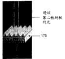
参照图9B,第二散射板175包括多个第二图案,并根据图案形状、大小以及透射率控制功能来控制灯图像的范围和亮度。即,第二散射板175在与图8的各灯124相对应的位置或者散射了光的区域中的光进行分光,并将光散射到该位置的两侧区域。第二散射板175减少了与灯124相对应的位置或者散射了光的区域中的光量。根据图9B,证实了在与灯124相对应的位置(即,灯124正上方的位置)中的光量被减少。光在与灯124的相对应位置的两侧区域中比在与灯124相对应的位置更亮。因此,当从一个灯发出的光透过第二散射板175时,透过的光似乎是从两个灯发出的。Referring to FIG. 9B , the
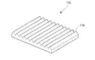
图11A到图11C是例示根据本发明的第二散射板的各种图案的立体图。11A to 11C are perspective views illustrating various patterns of the second diffusion plate according to the present invention.
在图11A和图11C中,第二散射板175具有面向图7的第一散射板170和图7的灯124的第三表面以及与该第三表面相反且面向图7的液晶面板110的第四表面。第二散射板175的第三表面是平坦的,并且第二散射板175的第四表面包括不平坦的第二图案176。第二图案176分别具有棱镜形状(其具有三角形截面)并与灯124平行设置。第二图案176可以具有沿着与灯124平行的第一方向延伸的长条形形状。如图11A中所示,第二图案176可以具有同样的高度的峰。如图11B所示,第二图案176可以包括彼此相邻并且具有不同的高度的峰的第一部分和第二部分。各第二图案176可以各具有如图11C所示的不同高度。In FIGS. 11A and 11C, the
有利地是,第二图案176可以具有50μm到500μm范围内的节距(相邻峰之间的距离)和20μm到400μm范围内的高度。第二图案176可以按规则节距设置,并且第二图案176可以按相邻两峰之间的在50μm到500μm范围内的不同节距不规则地(即,随机地)设置。Advantageously, the
第二散射板175可以由聚甲基丙烯酸甲酯(PMMA:polymethylmethacrylate)、聚苯乙烯(PS:polystyrene)、聚碳酸酯(PC:polycarbonate)、环烯烃聚合物(COC:cyclo-olefin copolymers)、聚对苯二甲酸乙二醇酯(PET:polyethylene terephthalate)、聚对苯二甲酸丁二醇酯(PBT:polybutylene terephtalate)以及塑料合金中的一种的与第一散射板170相同的材料形成。优选的是,包括第二图案176的第二散射板175具有0.6mm到3mm的厚度。The
图12是示出透过根据本发明的LCD模块的第一散射板和第二散射板的光的状态的图。FIG. 12 is a diagram illustrating the state of light transmitted through the first and second diffusion plates of the LCD module according to the present invention.
参照图8和图12,在根据本发明的LCD模块中,第一散射板170将从一个灯124发出的光散射到比该灯124的直径更宽的区域中,第二散射板175减少了对应于该区域的光量,并将这些光分光到该区域的两侧。因此,即使以第一距离S(其大于相关技术的第一距离且小于或等于相关技术的第一距离的两倍)设置灯124,也能够以几乎没有亮度差(即,基本在图7的液晶面板110的整个区域上亮度都是均匀的)的方式对图7的液晶面板110提供光。Referring to FIGS. 8 and 12, in the LCD module according to the present invention, the
这里,相邻灯124之间的第一距离S与反射片122和第一散射板125之间的第二距离D之比(即第一距离S比第二距离D的值(可以称为距离比S/D))可以大于0并小于或等于2.75。因此,即使距离比S/D在1.35到2.75的范围内,在图7的LCD模块101中也不存在由于亮度差造成的云纹缺陷。Here, the ratio of the first distance S between
可以通过增大第一距离S或者减小第二距离D来提高距离比S/D。如果增大了第一距离S,则图7的相邻灯124之间的距离增大,并且灯124的数量减少。相应地,减少了功耗,并且降低了制造成本。同时,如果第二距离D减小,则减小了背光单元120的厚度,并且图7的LCD模块101也相对变薄。The distance ratio S/D can be increased by increasing the first distance S or decreasing the second distance D. If the first distance S is increased, the distance between
即使在根据本发明的图7的LCD模块包括比相关技术更多的第一散射板170和第二散射板175,第一散射板170和第二散射板175也只有3mm的厚度。另一方面,与相关技术相比,可以将图7的反射片122和图7的第一散射板170之间的第二距离减少大于3mm的值,以使得距离比在不存在云纹缺陷的范围内。因此,根据本发明的LCD模块可以比相关技术更薄。Even though the LCD module of FIG. 7 according to the present invention includes more first and
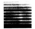
图13A是示出在根据相关技术的LCD模块中显示的白色图像的照片,而图13B是示出在根据本发明的LCD模块中显示的白色图像的照片。该LCD模块包括按距离比S/D为2.75排列的灯,其中,在相关技术的LCD模块中从灯到的散射板的距离等于本发明的LCD模块中从灯到的散射板的距离。例如,LCD模块可以是42英寸模块,在该模块中可以设置9个灯。当距离比为1.35时,42英寸模块包括16个灯。FIG. 13A is a photograph showing a white image displayed in an LCD module according to the related art, and FIG. 13B is a photograph showing a white image displayed in an LCD module according to the present invention. The LCD module includes lamps arranged at a distance ratio S/D of 2.75, wherein the distance from the lamps to the diffusion plate in the LCD module of the related art is equal to the distance from the lamps to the diffusion plate in the LCD module of the present invention. For example, the LCD module can be a 42 inch module in which 9 lights can be placed. When the distance ratio is 1.35, the 42 inch module includes 16 lamps.
如图13A所示,在相关技术的LCD模块中,以超出散射板的散射能力的方式来设置灯,并且会出现重复呈现出条形形状的亮部和暗部的云纹缺陷。As shown in FIG. 13A , in the LCD module of the related art, lamps are arranged in such a way as to exceed the scattering ability of the diffusion plate, and moiré defects in which bright and dark portions repeatedly appear in a stripe shape occur.
然而,如图13B中所示,在本发明的LCD模块中,没有呈现出条形形状的亮部和暗部,并且以均匀亮度在大体整个区域上显示了白色图像。However, as shown in FIG. 13B , in the LCD module of the present invention, there are no bright and dark portions exhibiting a stripe shape, and a white image is displayed with uniform luminance over substantially the entire area.
同时,第一散射板和第二散射板可以彼此替代,并且能够得到相同的结果。也就是说,即使第二散射板与灯相邻设置,并且第一散射板设置在第二散射板上方,也不存在由于亮度差造成的云纹缺陷。Meanwhile, the first diffusion plate and the second diffusion plate can be substituted for each other, and the same result can be obtained. That is to say, even if the second diffusion plate is disposed adjacent to the lamp, and the first diffusion plate is disposed above the second diffusion plate, there is no moiré defect due to brightness difference.
显然,本领域技术人员可以在不脱离本发明的精神或范围的情况下对本发明进行各种修改和变型。因而,本发明在落入所附权利要求及其等同物的范围内的条件下旨在涵盖本发明的修改和变型。It will be apparent to those skilled in the art that various modifications and variations can be made to the present invention without departing from the spirit or scope of the invention. Thus, it is intended that the present invention covers the modifications and variations of this invention provided they come within the scope of the appended claims and their equivalents.
Claims (15)
Translated fromChineseApplications Claiming Priority (3)
| Application Number | Priority Date | Filing Date | Title |
|---|---|---|---|
| KR10-2008-0035057 | 2008-04-16 | ||
| KR1020080035057 | 2008-04-16 | ||
| KR1020080035057AKR101260839B1 (en) | 2008-04-16 | 2008-04-16 | Backlight unit and Liquid crystal display module having the same |
Publications (2)
| Publication Number | Publication Date |
|---|---|
| CN101561119A CN101561119A (en) | 2009-10-21 |
| CN101561119Btrue CN101561119B (en) | 2012-04-04 |
Family
ID=41200829
Family Applications (1)
| Application Number | Title | Priority Date | Filing Date |
|---|---|---|---|
| CN2008101846820AActiveCN101561119B (en) | 2008-04-16 | 2008-12-15 | Backlight unit and liquid crystal display module including the same |
Country Status (3)
| Country | Link |
|---|---|
| US (1) | US8212964B2 (en) |
| KR (1) | KR101260839B1 (en) |
| CN (1) | CN101561119B (en) |
Families Citing this family (8)
| Publication number | Priority date | Publication date | Assignee | Title |
|---|---|---|---|---|
| KR101513716B1 (en)* | 2008-09-18 | 2015-04-21 | 삼성디스플레이 주식회사 | Backlight assembly and liquid crystal display device having the same |
| US8870400B2 (en)* | 2009-11-20 | 2014-10-28 | Sharp Kabushiki Kaisha | Optical member, lighting device, display device and television receiver, and method of manufacturing the optical member |
| CN102109101B (en)* | 2009-12-29 | 2012-10-17 | 财团法人工业技术研究院 | Surface light source module and optical film |
| KR101282029B1 (en)* | 2013-01-31 | 2013-07-04 | 삼성전자주식회사 | Display module and displyay apparatus having the same |
| JP2015088420A (en)* | 2013-11-01 | 2015-05-07 | 株式会社デンソー | Backlight unit |
| CN103807727A (en)* | 2014-01-16 | 2014-05-21 | 北京京东方光电科技有限公司 | Backlight module and display device |
| US11054700B2 (en)* | 2017-04-26 | 2021-07-06 | Citizen Electronics Co., Ltd. | Backlight |
| CN112086014B (en)* | 2020-09-16 | 2022-03-08 | 武汉华星光电技术有限公司 | Backlight module and display device |
Citations (3)
| Publication number | Priority date | Publication date | Assignee | Title |
|---|---|---|---|---|
| CN1969202A (en)* | 2004-06-18 | 2007-05-23 | 东丽株式会社 | Anisotropic diffusion film |
| CN101019046A (en)* | 2005-05-31 | 2007-08-15 | 索尼株式会社 | Liquid crystal display, method for producing optical sheet, and optical sheet |
| CN101055324A (en)* | 2006-04-14 | 2007-10-17 | 索尼株式会社 | Optical sheet, backlight device and liquid crystal display device |
Family Cites Families (9)
| Publication number | Priority date | Publication date | Assignee | Title |
|---|---|---|---|---|
| JPH07121097B2 (en)* | 1988-11-18 | 1995-12-20 | 株式会社日立製作所 | Liquid crystal television and manufacturing method thereof |
| CA2097109C (en)* | 1992-06-01 | 2000-01-11 | Shozo Kokawa | Liquid crystal display |
| AU2002359708A1 (en)* | 2001-12-14 | 2003-07-15 | Digital Optics International Corporation | Uniform illumination system |
| KR20060078871A (en) | 2004-12-30 | 2006-07-05 | 삼성전자주식회사 | Backlight assembly with a novel diffuser plate and flat panel display device |
| KR20060086628A (en) | 2005-01-27 | 2006-08-01 | 삼성전자주식회사 | Light control plate and liquid crystal display including the same |
| KR20070007648A (en) | 2005-07-11 | 2007-01-16 | 삼성전자주식회사 | Bidirectional light transmissive transflective prism sheet, bidirectional backlight assembly and bidirectional liquid crystal display comprising the same |
| JP2007103154A (en) | 2005-10-04 | 2007-04-19 | Furukawa Electric Co Ltd:The | Surface light source device |
| KR100932606B1 (en) | 2006-04-28 | 2009-12-17 | 주식회사 엘지화학 | Optical film and backlight unit including same |
| US7766528B2 (en)* | 2006-11-15 | 2010-08-03 | 3M Innovative Properties Company | Back-lit displays with high illumination uniformity |
- 2008
- 2008-04-16KRKR1020080035057Apatent/KR101260839B1/enactiveActive
- 2008-12-15CNCN2008101846820Apatent/CN101561119B/enactiveActive
- 2008-12-18USUS12/338,804patent/US8212964B2/enactiveActive
Patent Citations (3)
| Publication number | Priority date | Publication date | Assignee | Title |
|---|---|---|---|---|
| CN1969202A (en)* | 2004-06-18 | 2007-05-23 | 东丽株式会社 | Anisotropic diffusion film |
| CN101019046A (en)* | 2005-05-31 | 2007-08-15 | 索尼株式会社 | Liquid crystal display, method for producing optical sheet, and optical sheet |
| CN101055324A (en)* | 2006-04-14 | 2007-10-17 | 索尼株式会社 | Optical sheet, backlight device and liquid crystal display device |
Non-Patent Citations (2)
| Title |
|---|
| JP特开2004-311263A 2004.11.04 |
| US5,442,523A 1995.08.15 |
Also Published As
| Publication number | Publication date |
|---|---|
| KR20090109690A (en) | 2009-10-21 |
| US20090262281A1 (en) | 2009-10-22 |
| KR101260839B1 (en) | 2013-05-06 |
| US8212964B2 (en) | 2012-07-03 |
| CN101561119A (en) | 2009-10-21 |
Similar Documents
| Publication | Publication Date | Title |
|---|---|---|
| US8581942B2 (en) | Backlight unit for liquid crystal display device and driving method of the same | |
| CN100437716C (en) | Led backlight assembly and LCD device using same | |
| US10228589B2 (en) | Backlight unit and liquid crystal display device including the same | |
| US9618682B2 (en) | Optical sheet and backlight unit and display device comprising the same | |
| US7973873B2 (en) | Liquid crystal display module including light-blocking tape | |
| CN101561119B (en) | Backlight unit and liquid crystal display module including the same | |
| US8045092B2 (en) | Multifunctional optical sheet and liquid crystal display device including the same | |
| US8045093B2 (en) | Backlight unit and liquid crystal display device having the same | |
| EP3121645B1 (en) | Liquid crystal display device | |
| CN101646961B (en) | Optical film and backlight unit with same | |
| CN101922652B (en) | Backlight unit and liquid crystal display device having the same | |
| CN101769476A (en) | Backlight unit and liquid crystal display module including the same | |
| KR20160022224A (en) | Light guide plate and backlight unit having the same | |
| US20100165243A1 (en) | Prism sheet, back light unit and liquid crystal display device having the same | |
| CN101688649B (en) | Lighting devices, display devices, television receivers | |
| CN101688648B (en) | Lighting devices, display devices, television receivers | |
| WO2016194716A1 (en) | Edge-lit backlight device and liquid crystal display device | |
| KR101272054B1 (en) | Liquid crystal display device | |
| GB2544895A (en) | Backlight unit and liquid crystal display device including the same | |
| CN101071223A (en) | Backlight unit and liquid crystal display device having the same | |
| KR101413140B1 (en) | Light diffusion plate having non-uniform local microlens array pattern and liquid crystal display device comprising the same | |
| TWI498641B (en) | Backlight unit and liquid crystal display device including the same | |
| KR101296456B1 (en) | Back light Unit and Liquid Crystal Display using the same | |
| KR100877411B1 (en) | Luminance enhancement sheet, backlight device comprising same, liquid crystal display, and manufacturing method thereof | |
| KR20080022717A (en) | Backlight unit |
Legal Events
| Date | Code | Title | Description |
|---|---|---|---|
| C06 | Publication | ||
| PB01 | Publication | ||
| C10 | Entry into substantive examination | ||
| SE01 | Entry into force of request for substantive examination | ||
| C14 | Grant of patent or utility model | ||
| GR01 | Patent grant |