Movatterモバイル変換


[0]ホーム

URL:


CN101560972A - Fluid delivery device with flow channel plate - Google Patents

Fluid delivery device with flow channel plate
Download PDF

Info

Publication number
CN101560972A
CN101560972ACNA2008100922691ACN200810092269ACN101560972ACN 101560972 ACN101560972 ACN 101560972ACN A2008100922691 ACNA2008100922691 ACN A2008100922691ACN 200810092269 ACN200810092269 ACN 200810092269ACN 101560972 ACN101560972 ACN 101560972A
Authority
CN
China
Prior art keywords
valve body
valve
channel
outlet
inlet
Prior art date
Legal status (The legal status is an assumption and is not a legal conclusion. Google has not performed a legal analysis and makes no representation as to the accuracy of the status listed.)
Granted
Application number
CNA2008100922691A
Other languages
Chinese (zh)
Other versions
CN101560972B (en
Inventor
余荣侯
陈世昌
邱士哲
周宗柏
Current Assignee (The listed assignees may be inaccurate. Google has not performed a legal analysis and makes no representation or warranty as to the accuracy of the list.)
Microjet Technology Co Ltd
Original Assignee
Microjet Technology Co Ltd
Priority date (The priority date is an assumption and is not a legal conclusion. Google has not performed a legal analysis and makes no representation as to the accuracy of the date listed.)
Filing date
Publication date
Application filed by Microjet Technology Co LtdfiledCriticalMicrojet Technology Co Ltd
Priority to CN2008100922691ApriorityCriticalpatent/CN101560972B/en
Publication of CN101560972ApublicationCriticalpatent/CN101560972A/en
Application grantedgrantedCritical
Publication of CN101560972BpublicationCriticalpatent/CN101560972B/en
Activelegal-statusCriticalCurrent
Anticipated expirationlegal-statusCritical

Links

Images

Landscapes

Abstract

The invention is a fluid conveying device with a flow passage plate, which is used for conveying fluid and comprises: a valve body seat having at least one outlet passage and at least one inlet passage; the runner plate is provided with two side surfaces, and a plurality of inlet branch runners and a plurality of outlet converging runners which penetrate through the two side surfaces; the valve body cover body is arranged on the runner plate; the valve body film is arranged between the runner plate and the valve body cover body and is provided with a plurality of valve structures; the temporary storage chambers are arranged between the valve body film and the valve body cover body and between the valve body film and the runner plate; the vibration device is provided with a vibration film and at least one actuator, the periphery of the vibration device is fixedly arranged on the valve body cover body, and at least one pressure chamber is formed by the vibration device and the valve body cover body.

Description

Translated fromChinese
具有流道板的流体输送装置Fluid delivery device with flow channel plate

技术领域technical field

本发明是关于一种流体输送装置,尤指一种具有流道板的流体输送装置。The invention relates to a fluid delivery device, in particular to a fluid delivery device with a channel plate.

背景技术Background technique

目前于各领域中无论是医药、电脑科技、打印、能源等工业,产品均朝精致化及微小化方向发展,其中微泵、喷雾器、喷墨头、工业打印装置等产品所包含的流体输送结构为其关键技术,因此,如何借助创新结构突破其技术瓶颈,为发展的重要内容。At present, in various fields, whether it is medicine, computer technology, printing, energy and other industries, products are developing towards refinement and miniaturization. Among them, the fluid delivery structures included in products such as micropumps, sprayers, inkjet heads, and industrial printing devices As its key technology, how to break through its technical bottleneck with the help of innovative structure is an important content of development.

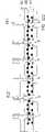
请参阅图1,其是已知微泵结构的结构示意图,已知微泵结构10是由阀体座11、阀体盖体12、阀体薄膜13、微致动器14及盖体15所组成,其中,阀体薄膜13包含入口阀门结构131及出口阀门结构132,阀体座11包含入口通道111及出口通道112、阀体盖体12与微致动器14间形成一压力腔室123,阀体薄膜13设置在阀体座11与阀体盖体12之间。Please refer to Fig. 1, it is the structural representation of known micropump structure, knownmicropump structure 10 is made up ofvalve body seat 11, valvebody cover body 12,valve body film 13,microactuator 14 andcover body 15 Composition, wherein,valve body film 13 comprisesinlet valve structure 131 andoutlet valve structure 132,valve body seat 11 comprisesinlet channel 111 andoutlet channel 112, and apressure chamber 123 is formed betweenvalve body cover 12 andmicroactuator 14 , Thevalve body film 13 is arranged between thevalve body seat 11 and thevalve body cover 12 .

当一电压作用在微致动器14的上下两极时,会产生一电场,使得微致动器14在此电场的作用下产生弯曲,当微致动器14朝箭号x所指的方向向上弯曲变形,将使得压力腔室123的体积增加,因而产生一吸力,使阀体薄膜13的入口阀门结构131开启,使液体可自阀体座11上的入口通道111被吸取进来,并流经阀体薄膜13的入口阀门结构131及阀体盖体12上的入口阀片通道121而流入压力腔室123内,反之当微致动器14因电场方向改变而朝箭号x的反方向向下弯曲变形时,则会压缩压力腔室123的体积,使得压力腔室123对内部的流体产生一推力,并使阀体薄膜13的入口阀门结构131、出口阀门结构132承受一向下推力,而出口阀门结构132将开启,并使液体由压力腔室123通过阀体盖体12上的出口阀门通道122、阀体薄膜13的出口阀门结构132,而从阀体座11的出口通道112流出微泵结构10外,因而完成流体的传输过程。When a voltage acts on the upper and lower poles of themicroactuator 14, an electric field will be generated, causing themicroactuator 14 to bend under the action of the electric field. When themicroactuator 14 moves upward in the direction indicated by the arrow x The bending deformation will increase the volume of thepressure chamber 123, thereby generating a suction force, so that theinlet valve structure 131 of thevalve body film 13 is opened, so that the liquid can be sucked in from theinlet channel 111 on thevalve body seat 11 and flow through Theinlet valve structure 131 of thevalve body film 13 and the inletvalve plate channel 121 on thevalve body cover 12 flow into thepressure chamber 123. On the contrary, when themicroactuator 14 moves in the opposite direction of the arrow x due to the change of the direction of the electric field When bending and deforming downward, the volume of thepressure chamber 123 will be compressed, so that thepressure chamber 123 will generate a thrust to the internal fluid, and theinlet valve structure 131 and theoutlet valve structure 132 of thevalve body film 13 will bear a downward thrust, while Theoutlet valve structure 132 will be opened, and the liquid will flow out from theoutlet channel 112 of thevalve body seat 11 from thepressure chamber 123 through theoutlet valve channel 122 on thevalve body cover 12 and theoutlet valve structure 132 of thevalve body film 13.Pump structure 10, thus completing the fluid transmission process.

虽然已知微泵结构10能够达到输送流体的功能,但是其是使用单一致动器配合单一压力腔室、单一流通管道、单一进出口以及单一对的阀门结构设计,若要使用微泵结构10来提升流量,必须利用衔接机构将多个微泵结构10进行连接并堆迭设置,然而此种连接方式除了需额外耗费衔接机构的成本外,多个微泵结构10所组合起来的体积将过大,使得最终产品的体积增加而无法符合微小化的趋势。Although the knownmicropump structure 10 can achieve the function of transporting fluid, it uses a single actuator to cooperate with a single pressure chamber, a single flow channel, a single inlet and outlet, and a single pair of valve structure designs. If themicropump structure 10 is to be used In order to increase the flow rate, a plurality ofmicropump structures 10 must be connected and stacked by using a connecting mechanism. However, in addition to the additional cost of the connecting mechanism, the combined volume of themultiple micropump structures 10 will be too large. Large, so that the volume of the final product increases and cannot meet the trend of miniaturization.

因此,如何发展一种可改善上述现有技术缺失的具有流道板的流体输送装置,实为目前迫切需要解决的问题。Therefore, how to develop a fluid conveying device with a flow channel plate that can improve the above-mentioned deficiencies in the prior art is an urgent problem to be solved at present.

发明内容Contents of the invention

本发明的主要目的在于提供一种具有流道板的流体输送装置,以解决以已知微泵结构来提升流量时,必须利用衔接机构将多个微泵结构进行连接并堆迭设置,将额外耗费衔接机构的成本,且多个微泵结构所组合起来的体积过大,无法符合产品微小化的趋势等缺点。The main purpose of the present invention is to provide a fluid conveying device with a flow channel plate to solve the problem that when using the known micropump structure to increase the flow rate, a plurality of micropump structures must be connected and stacked by means of an engagement mechanism, and the additional The cost of connecting mechanism is consumed, and the combined volume of multiple micropump structures is too large, which cannot meet the trend of product miniaturization.

为达上述目的,本发明的一较广义实施样态为提供一种具有流道板的流体输送装置,用以传送流体,其包含:阀体座,其具有至少一出口通道及至少一入口通道;流道板,其具有两侧面,以及贯穿两侧面的多个入口分流道及多个出口汇流道;阀体盖体,其与该流道板相互堆迭结合;阀体薄膜,其设置于流道板及阀体盖体之间,且具有多个阀门结构;多个暂存室,设置于阀体薄膜与阀体盖体之间,以及于阀体薄膜与流道板之间;以及振动装置,其具有振动薄膜及至少一致动器,且周边固设于阀体盖体,并与阀体盖体形成至少一压力腔室。In order to achieve the above object, a broader embodiment of the present invention is to provide a fluid conveying device with a channel plate for conveying fluid, which includes: a valve body seat, which has at least one outlet channel and at least one inlet channel ; the flow channel plate, which has two sides, and a plurality of inlet runners and a plurality of outlet confluence channels running through the two sides; the valve body cover, which is stacked and combined with the flow channel plate; the valve body film, which is arranged on Between the flow channel plate and the valve body cover, there are multiple valve structures; multiple temporary storage rooms are arranged between the valve body film and the valve body cover, and between the valve body film and the flow channel plate; and The vibrating device has a vibrating membrane and at least one actuator, and its periphery is fixed on the valve body cover to form at least one pressure chamber with the valve body cover.

为达上述目的,本发明的另一较广义实施样态为提供一种具有流道板的流体输送装置,用以传送流体,其包含:阀体座,其具有出口通道及入口通道;流道板,其具有两侧面,以及贯穿两侧面的入口分流道及出口汇流道;阀体盖体,其与该流道板相互堆迭结合;阀体薄膜,其设置于流道板及阀体盖体之间,且具有第一阀门结构及第二阀门结构;多个暂存室,设置于阀体薄膜与阀体盖体之间,以及于阀体薄膜与流道板之间;以及振动装置,其具有振动薄膜及单一致动器,且周边固设于阀体盖体,并与阀体盖体形成单一压力腔室。In order to achieve the above purpose, another broad implementation of the present invention is to provide a fluid delivery device with a flow channel plate for delivering fluid, which includes: a valve body seat, which has an outlet channel and an inlet channel; a flow channel A plate, which has two sides, and an inlet runner and an outlet confluence channel running through the two sides; a valve body cover, which is stacked and combined with the runner plate; a valve body film, which is arranged on the runner plate and the valve body cover between the body, and has a first valve structure and a second valve structure; a plurality of temporary storage chambers, arranged between the valve body film and the valve body cover, and between the valve body film and the flow channel plate; and the vibration device , which has a vibrating membrane and a single actuator, and the periphery is fixed on the valve body cover, and forms a single pressure chamber with the valve body cover.

附图说明Description of drawings

图1是已知微泵结构的结构示意图。Fig. 1 is a structural schematic diagram of a known micropump structure.

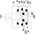
图2A是本发明第一较佳实施例的流体输送装置的分解结构示意图。Fig. 2A is a schematic diagram of an exploded structure of a fluid delivery device according to a first preferred embodiment of the present invention.

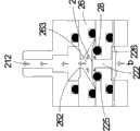
图2B是图2A所示的流道板的背面结构示意图。Fig. 2B is a schematic diagram of the back structure of the channel plate shown in Fig. 2A.

图2C是图2A所示的阀体盖体的背面结构示意图。FIG. 2C is a schematic diagram of the back structure of the valve body cover shown in FIG. 2A .

图2D是图2A所示的入口阀门结构开启示意图。Fig. 2D is a schematic diagram of opening the inlet valve structure shown in Fig. 2A.

图2E是图2A所示的出口阀门结构开启示意图。Fig. 2E is a schematic diagram of opening the outlet valve structure shown in Fig. 2A.

图2F是图2A的组装完成后的结构示意图。FIG. 2F is a schematic diagram of the assembled structure of FIG. 2A .

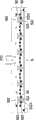
图3A是本发明图2F所示的流体输送装置的未动作状态的A-A剖面示意图。Fig. 3A is an A-A cross-sectional schematic view of the non-operating state of the fluid delivery device shown in Fig. 2F of the present invention.

图3B是图3A的压力腔室膨胀状态示意图。Fig. 3B is a schematic diagram of the expanded state of the pressure chamber in Fig. 3A.

图3C是图3A的压力腔室压缩状态示意图。FIG. 3C is a schematic diagram of the compressed state of the pressure chamber in FIG. 3A .

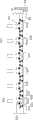
图4A是本发明图2F所示的流体输送装置的未动作状态的B-B剖面示意图。Fig. 4A is a B-B cross-sectional schematic view of the non-operating state of the fluid delivery device shown in Fig. 2F of the present invention.

图4B是图4A的压力腔室压缩状态示意图。FIG. 4B is a schematic diagram of the compressed state of the pressure chamber in FIG. 4A .

图4C是图4A的压力腔室膨胀状态示意图。FIG. 4C is a schematic diagram of the expanded state of the pressure chamber in FIG. 4A .

图5A是本发明第二较佳实施例的流体输送装置的分解结构示意图。Fig. 5A is a schematic diagram of an exploded structure of a fluid delivery device according to a second preferred embodiment of the present invention.

图5B是图5A的组装完成后的结构示意图。FIG. 5B is a schematic diagram of the assembled structure of FIG. 5A .

图6A是本发明图5B所示的流体输送装置的未动作状态的A-A剖面示意图。Fig. 6A is an A-A cross-sectional schematic view of the non-operating state of the fluid delivery device shown in Fig. 5B of the present invention.

图6B是图6A的压力腔室膨胀状态示意图。Fig. 6B is a schematic diagram of the expanded state of the pressure chamber in Fig. 6A.

图6C是图6A的压力腔室压缩状态示意图。FIG. 6C is a schematic diagram of the compressed state of the pressure chamber in FIG. 6A .

图7A是本发明图5B所示的流体输送装置的未动作状态的B-B剖面示意图。Fig. 7A is a schematic B-B sectional view of the non-operating state of the fluid delivery device shown in Fig. 5B of the present invention.

图7B是图7A的压力腔室压缩状态示意图。Fig. 7B is a schematic diagram of the compressed state of the pressure chamber in Fig. 7A.

图7C是图7A的压力腔室膨胀状态示意图。Fig. 7C is a schematic diagram of the expanded state of the pressure chamber in Fig. 7A.

图8是本发明第三较佳实施例的流体输送装置的结构示意图。Fig. 8 is a schematic structural view of a fluid delivery device according to a third preferred embodiment of the present invention.

图9A是本发明图8所示的流体输送装置的未动作状态的A-A剖面示意图。FIG. 9A is an A-A cross-sectional schematic view of the non-operating state of the fluid delivery device shown in FIG. 8 of the present invention.

图9B是图9A的压力腔室膨胀状态示意图。Fig. 9B is a schematic diagram of the expanded state of the pressure chamber in Fig. 9A.

图9C是图9A的压力腔室压缩状态示意图。FIG. 9C is a schematic diagram of the compressed state of the pressure chamber in FIG. 9A .

图10A是本发明图8所示的流体输送装置的未动作状态的B-B剖面示意图。FIG. 10A is a B-B cross-sectional schematic view of the non-operating state of the fluid delivery device shown in FIG. 8 of the present invention.

图10B是图10A的压力腔室压缩状态示意图。FIG. 10B is a schematic diagram of the compressed state of the pressure chamber of FIG. 10A .

图10C是图10A的压力腔室膨胀状态示意图。FIG. 10C is a schematic diagram of the expanded state of the pressure chamber in FIG. 10A .

具体实施方式Detailed ways

体现本发明特征与优点的一些典型实施例将在下面的说明中详细叙述。应理解的是本发明能够在不同的态样上具有各种的变化,其皆不脱离本发明的范围,且其中的说明及图示在本质上是当作说明之用,而非用以限制本发明。Some typical embodiments embodying the features and advantages of the present invention will be described in detail in the following description. It should be understood that the invention is capable of various changes in different aspects without departing from the scope of the invention, and that the description and illustrations therein are illustrative in nature and not limiting. this invention.

本发明的流体输送装置可适用于医药生技、电脑科技、打印或是能源等工业,且可为但不限为输送气体或是液体,主要是借助增加流道板的设计可扩充成一进一出、多进一出、一进多出以及多进多出的形式,较易使流体均匀提供至入口分流道,并能使出口流体有效汇集至出口通道。除此之外,流体输送装置整体设计采用长条形舱体,其对应长条形的振动薄膜及致动器,可使流速及扬程大为增加,非常适合用于流速及扬程需求相对较高的应用场合。The fluid conveying device of the present invention can be applied to industries such as medical biotechnology, computer technology, printing or energy, and can be but not limited to conveying gas or liquid. Outlet, multi-inlet-one-outlet, one-inlet-multiple-outlet, and multi-inlet-multiple-outlet forms make it easier to provide the fluid evenly to the inlet channel, and to effectively collect the outlet fluid into the outlet channel. In addition, the overall design of the fluid conveying device adopts a strip-shaped cabin, which corresponds to a strip-shaped vibrating membrane and an actuator, which can greatly increase the flow rate and lift, and is very suitable for relatively high flow rate and lift requirements. application occasions.

请参阅图2A,其是本发明第一较佳实施例的流体输送装置的结构示意图,如图所示,本实施例的流体输送装置20是使用一进一出的实施态样,流体输送装置20主要是由阀体座21、阀体盖体22、阀体薄膜23、多个暂存室、致动装置24、盖体25及流道板26所组成,其中在阀体盖体22及致动装置24之间形成一压力腔室226(如图2C所示),主要用来储存流体。Please refer to FIG. 2A , which is a schematic structural view of a fluid delivery device in a first preferred embodiment of the present invention. As shown in the figure, thefluid delivery device 20 of this embodiment uses a one-in-one-out implementation. Thefluid delivery device 20 is mainly composed of avalve body seat 21, avalve body cover 22, avalve body film 23, a plurality of temporary storage chambers, anactuator 24, acover body 25 and arunner plate 26, wherein the valvebody cover body 22 and A pressure chamber 226 (shown in FIG. 2C ) is formed between theactuating devices 24 and is mainly used to store fluid.

流体输送装置20的组装方式是将流道板26设置于阀体座21与阀体薄膜23之间,而阀体薄膜23则设置于流道板26及阀体盖体22之间,并使阀体薄膜23与流道板26及阀体盖体22相对应设置,且在阀体薄膜23与阀体盖体22之间形成一第一暂存室,而在阀体薄膜23与流道板26之间形成一第二暂存室,并且于阀体盖体22上的相对应位置还设置有致动装置24,致动装置24是由一振动薄膜241以及一致动器242组装而成(如图3A及图4A所示),用以驱动流体输送装置20的动作,最后,依序将阀体座21、流道板26、阀体薄膜23、阀体盖体22、致动装置24及盖体25相对应堆迭设置,以完成流体输送装置20的组装(如图2F所示)。The assembly method of thefluid delivery device 20 is that theflow channel plate 26 is arranged between thevalve body seat 21 and thevalve body film 23, and thevalve body film 23 is arranged between theflow channel plate 26 and thevalve body cover 22, and makes Thevalve body film 23 is arranged corresponding to theflow channel plate 26 and thevalve body cover 22, and a first temporary storage chamber is formed between thevalve body film 23 and thevalve body cover 22, and between thevalve body film 23 and the flow channel A second temporary storage chamber is formed between theplates 26, and anactuating device 24 is also arranged at a corresponding position on thevalve body cover 22. Theactuating device 24 is assembled by a vibratingfilm 241 and an actuator 242 ( 3A and 4A), to drive the action of thefluid delivery device 20, and finally, thevalve body seat 21, theflow channel plate 26, thevalve body film 23, thevalve body cover 22, theactuator 24 and thecover body 25 are stacked correspondingly to complete the assembly of the fluid delivery device 20 (as shown in FIG. 2F ).

其中,阀体座21、流道板26及阀体盖体22是本发明流体输送装置20中导引流体进出的主要结构,请参阅图2A并配合图3A及图4A,其中图3A是图2F所示的流体输送装置组装完成的A-A剖面图,图4A是图2F示的流体输送装置组装完成的B-B剖面图,如图所示,阀体座21具有一个入口通道211以及出口通道212,入口通道211是用以使外部的流体输送至流体输送装置20内,而出口通道212则是将流体由流体输送装置20的内部传送至外部。Among them, thevalve body seat 21, theflow channel plate 26 and thevalve body cover 22 are the main structures for guiding fluid in and out in thefluid delivery device 20 of the present invention. Please refer to FIG. 2A and cooperate with FIG. 3A and FIG. 4A, wherein FIG. 2F shows the assembled A-A sectional view of the fluid delivery device. FIG. 4A is a B-B sectional view of the assembled fluid delivery device shown in FIG. 2F. As shown in the figure, thevalve body seat 21 has aninlet channel 211 and anoutlet channel 212. Theinlet channel 211 is used to deliver the external fluid into thefluid delivery device 20 , and theoutlet channel 212 is used to deliver the fluid from the inside of thefluid delivery device 20 to the outside.

请参阅图2A、图2B并配合图3A及图4A,其中图2B是图2A所示的流道板的背面结构示意图,如图所示,流道板26具有单一个入口分流道261以及单一个出口汇流道262,且入口通道211与入口分流道261相连通(如图3A所示),而出口通道212则与出口汇流道262连通(如图4A所示),换言之,当流体输送装置20组装完成时,入口分流道261可通过入口通道211与外界连通,可将流体由外界输入,而出口汇流道262则可通过出口通道212与外界连通,可将流体由流体输送装置20内部输出至外界。Please refer to Fig. 2A and Fig. 2B together with Fig. 3A and Fig. 4A, wherein Fig. 2B is a schematic diagram of the back structure of the flow channel plate shown in Fig. 2A. Anoutlet confluence channel 262, and theinlet channel 211 communicates with the inlet sub-channel 261 (as shown in Figure 3A), while theoutlet channel 212 communicates with the outlet confluence channel 262 (as shown in Figure 4A), in other words, when thefluid delivery device 20. When the assembly is completed, theinlet shunt channel 261 can communicate with the outside world through theinlet channel 211, and the fluid can be input from the outside world, while theoutlet confluence channel 262 can communicate with the outside world through theoutlet channel 212, and the fluid can be output from the inside of thefluid delivery device 20. to the outside world.

并且,于本实施例中,阀体薄膜23及流道板26之间所形成的第二暂存室即为图中所示的出口暂存腔263,但不以此为限,其是由流道板26的下表面266与出口汇流道262相对应的位置产生部分凹陷而形成,并与阀体座21的出口通道212相连通,该出口暂存腔263是用以暂时储存流体,并使该流体由出口暂存腔263通过一出口汇流道262而输送至出口通道212,再流出阀体座21之外。以及,在流道板26上还具有多个凹槽结构,用以供一密封环27(如图3A及图4A所示)设置于其上,于本实施例中,流道板26的下表面具有环绕入口分流道261周边的凹槽265,及环绕于出口暂存腔263周边的凹槽264。Moreover, in this embodiment, the second temporary storage chamber formed between thevalve body film 23 and theflow channel plate 26 is the outlettemporary storage chamber 263 shown in the figure, but it is not limited thereto, it is formed by The lower surface 266 of theflow channel plate 26 is partially recessed at the position corresponding to theoutlet confluence channel 262, and communicates with theoutlet passage 212 of thevalve body seat 21. The outlettemporary storage chamber 263 is used for temporarily storing fluid and The fluid is delivered from the outlettemporary storage chamber 263 to theoutlet channel 212 through anoutlet confluence channel 262 , and then flows out of thevalve body seat 21 . And, there are also multiple groove structures on theflow channel plate 26 for a sealing ring 27 (as shown in FIG. 3A and FIG. 4A ) to be arranged on it. In this embodiment, the lower part of theflow channel plate 26 The surface has agroove 265 surrounding theinlet branch channel 261 and a groove 264 surrounding the outlettemporary storage chamber 263 .

请参阅图2A、图2C并配合图3A及图4A,其中图2C是图2A所示的阀体盖体的背面结构示意图,如图所示,阀体盖体22具有一上表面220及一下表面228,以及在阀体盖座22上亦具有贯穿上表面220至下表面228的第一阀门通道及一第二阀门通道,于本实施例中,第一阀门通道是一入口阀门通道221,第二阀门通道是一出口阀门通道222,且该入口阀门通道221设置于与流道板26的入口分流道261相对应的位置,而出口阀门通道222则设置于与流道板26的出口暂存腔263内的出口汇流道262相对应的位置,并且,于本实施例中,阀体薄膜23及阀体盖体22之间所形成的第一暂存室即为图中所示的入口暂存腔223,且不以此为限,其是由阀体盖体22之上表面220于与入口阀门通道221相对应的位置产生部份凹陷而形成,且其是连通于入口阀门通道221。Please refer to Fig. 2A, Fig. 2C together with Fig. 3A and Fig. 4A, wherein Fig. 2C is a schematic diagram of the back structure of the valve body cover shown in Fig. 2A, as shown in the figure, thevalve body cover 22 has anupper surface 220 and a lower surface Thesurface 228, and the valve body coverseat 22 also have a first valve passage and a second valve passage through theupper surface 220 to thelower surface 228. In this embodiment, the first valve passage is aninlet valve passage 221, The second valve channel is anoutlet valve channel 222, and theinlet valve channel 221 is arranged at a position corresponding to theinlet branch channel 261 of theflow channel plate 26, and theoutlet valve channel 222 is arranged at a temporary outlet of theflow channel plate 26. The corresponding position of theoutlet confluence channel 262 in thestorage chamber 263, and, in this embodiment, the first temporary storage chamber formed between thevalve body film 23 and thevalve body cover 22 is the inlet shown in the figureTemporary storage chamber 223, and not limited thereto, is formed by theupper surface 220 of the valve body cover 22 at the position corresponding to theinlet valve passage 221 and is formed by a partial depression, and it is communicated with theinlet valve passage 221 .

请再参阅图2C,如图所示,阀体盖体22的下表面228是部份凹陷,以形成一压力腔室226,其是与致动装置24的致动器242相对应设置,压力腔室226是通过入口阀门通道221连通于入口暂存腔223,并同时与出口阀门通道222相连通,因此,当致动器242受电压致动使致动装置24朝盖体25方向凸出变形,造成压力腔室226的体积膨胀而产生负压差,可使流体经入口阀门通道221流至压力腔室226内(如图3A及图4A所示),其后,当施加于致动器242的电场方向改变后,致动器242将使致动装置24朝阀体盖体22方向凹陷变形,压力腔室226将收缩而体积减小,使压力腔室226与外界产生正压力差,促使流体由出口阀门通道222流出压力腔室226之外,于此同时,同样有部分流体会流入入口阀门通道221及入口暂存室223内,然而由于此时的入口阀门结构231是使受压而关闭的状态,故该流体不会通过入口阀片2313而产生倒流的现象(如图3C所示),至于暂时储存于入口暂存腔223内的流体,则于致动器242再受电压致动,重复使致动装置24再变形而增加压力腔室226体积时,再由入口暂存腔223经至入口阀门通道221而流入压力腔室226内,以进行流体的输送。Please refer to FIG. 2C again, as shown in the figure, thelower surface 228 of thevalve body cover 22 is partially recessed to form apressure chamber 226, which is arranged corresponding to theactuator 242 of theactuator device 24, and the pressure Thechamber 226 communicates with the inlettemporary storage chamber 223 through theinlet valve channel 221, and communicates with theoutlet valve channel 222 at the same time. Therefore, when theactuator 242 is actuated by voltage, theactuator device 24 protrudes toward thecover body 25. The deformation causes the volume expansion of thepressure chamber 226 to generate a negative pressure difference, which can make the fluid flow into thepressure chamber 226 through the inlet valve channel 221 (as shown in Figure 3A and Figure 4A ), and thereafter, when applied to the actuating After the direction of the electric field of thedevice 242 is changed, theactuator 242 will cause theactuator 24 to deform in the direction of thevalve body cover 22, and thepressure chamber 226 will shrink and reduce in volume, so that a positive pressure difference will be generated between thepressure chamber 226 and the outside world. , prompting the fluid to flow out of thepressure chamber 226 from theoutlet valve passage 222, and at the same time, part of the fluid will also flow into theinlet valve passage 221 and the inlettemporary storage chamber 223. Therefore, the fluid will not flow back through the inlet valve plate 2313 (as shown in FIG. 3C ). Voltage actuation, repeated re-deformation of theactuating device 24 to increase the volume of thepressure chamber 226, then flows from the inlettemporary storage chamber 223 to theinlet valve channel 221 into thepressure chamber 226 for fluid delivery.

另外,阀体盖体22上同样具有多个凹槽结构,以本实施例为例,在阀体盖体22的下表面228具有环绕压力腔室226而设置的凹槽227,而在上表面220上则具有环绕设置于入口暂存腔223的凹槽224、环绕设置于出口阀门通道222的凹槽225,同样地,上述凹槽结构是用以供一密封环28(如图3A及图4A所示)设置于其中。In addition, the valve body cover 22 also has a plurality of groove structures. Taking this embodiment as an example, thelower surface 228 of thevalve body cover 22 hasgrooves 227 arranged around thepressure chamber 226, and the upper surface On 220, there is agroove 224 surrounding the inlettemporary storage chamber 223 and agroove 225 surrounding theoutlet valve channel 222. Similarly, the above groove structure is used for a sealing ring 28 (as shown in Fig. 3A and Fig. 4A) set in it.

请参阅图2A并配合图2D及图2E,其中图2D其是图2A所示的入口阀门结构开启示意图,图2E其是图2A所示的出口阀门结构开启示意图,如图2A所示,阀体薄膜23主要是以传统加工、或平版印刷(lithography)蚀刻、或激光加工、或电铸加工、或放电加工等方式制出,且为一厚度实质上相同的薄片结构,其上具有第一阀门结构以及第二阀门结构,于本实施例中,第一阀门结构是入口阀门结构231,而第二阀门结构是出口阀门结构232,其中,入口阀门结构231具有入口阀片2313以及多个环绕入口阀片2313周边而设置的镂空的孔2312,另外,在孔2312之间还具有与入口阀片2313相连接的延伸部2311,当阀体薄膜23承受一自压力腔室226传递而来向上的应力时,如图3C所示,入口阀门结构231是整个向上平贴于流道板26之上,此时入口阀片2313会紧靠凹槽265上密封环27突出部分,而密封住流道板26上的入口分流道261,且其外围的镂空孔2312及延伸部2311则顺势浮贴于流道板26之上,故因此入口阀门结构231的关闭作用,使流体无法流出。Please refer to Fig. 2A and Fig. 2D and Fig. 2E, wherein Fig. 2D is a schematic diagram of the opening of the inlet valve structure shown in Fig. 2A, Fig. 2E is a schematic diagram of the opening of the outlet valve structure shown in Fig. 2A, as shown in Fig. 2A, the valve The bulkthin film 23 is mainly produced by conventional processing, or lithography (lithography) etching, or laser processing, or electroforming processing, or electrical discharge processing, etc., and is a thin sheet structure with substantially the same thickness, on which there is a first The valve structure and the second valve structure, in this embodiment, the first valve structure is aninlet valve structure 231, and the second valve structure is anoutlet valve structure 232, wherein theinlet valve structure 231 has aninlet valve plate 2313 and a plurality of surroundingHollow holes 2312 are provided around theinlet valve plate 2313. In addition, there areextensions 2311 connected with theinlet valve plate 2313 between theholes 2312. When the stress is high, as shown in Figure 3C, theinlet valve structure 231 is flatly attached to theflow channel plate 26, and theinlet valve plate 2313 will be close to the protruding part of theseal ring 27 on thegroove 265 to seal the flow channel. Theinlet channel 261 on thechannel plate 26 , and thehollow holes 2312 andextensions 2311 around it float on thechannel plate 26 , so the fluid cannot flow out due to the closing function of theinlet valve structure 231 .

而当阀体薄膜23受到压力腔室226体积增加而产生的吸力作用下,由于设置于流道板26的凹槽265内的密封环27已提供入口阀门结构231一预力(Preforce),因而入口阀片2313可借助延伸部2311的支撑而产生更大的预盖紧效果,以防止逆流,当因压力腔室226的负压而使入口阀门结构231往下产生位移(如图2D所示),此时,流体则可通过镂空的孔2312由流道板26流至阀体盖体22的入口暂存腔223,并通过入口暂存腔223及入口阀门通道221传送至压力腔室226内,如此一来,入口阀门结构231即可响应压力腔室226产生的正负压力差而迅速的开启或关闭,以控制流体的进出,并使流体不会回流至流道板26上。And when thevalve body film 23 is subjected to the suction force generated by the increase in the volume of thepressure chamber 226, the sealingring 27 provided in thegroove 265 of theflow channel plate 26 has provided theinlet valve structure 231 with a preforce (Preforce), thus Theinlet valve plate 2313 can produce a greater pre-capping effect by means of the support of theextension part 2311 to prevent reverse flow. When theinlet valve structure 231 is displaced downward due to the negative pressure of the pressure chamber 226 (as shown in FIG. 2D ), at this time, the fluid can flow from theflow channel plate 26 to the inlettemporary storage chamber 223 of the valve body cover 22 through thehollow hole 2312, and then be sent to thepressure chamber 226 through the inlettemporary storage chamber 223 and theinlet valve channel 221 In this way, theinlet valve structure 231 can be quickly opened or closed in response to the positive and negative pressure difference generated by thepressure chamber 226 to control the inflow and outflow of fluid and prevent the fluid from flowing back to thechannel plate 26 .

同样地,位于同一阀体薄膜23上的另一阀门结构则为出口阀门结构232,其中的出口阀片2323、延伸部2321以及孔2322的动作方式均与入口阀门结构231相同,因而不再赘述,但出口阀门结构232周边的密封环28设置方向是与入口阀门结构231的密封环27反向设置,如图2E及图4A所示,因而当压力腔室226压缩而产生一推力时,设置于阀体盖体22的凹槽225内的密封环28将提供出口阀门结构232一预力(Preforce),使得出口阀片2323可借助延伸部2321的支撑而产生更大的预盖紧效果,以防止逆流,当因压力腔室226的正压而使出口阀门结构232往上产生位移,此时,流体则可通过镂空的孔2322由压力腔室226经阀体盖体22而流至流道板26的出口暂存腔263内,并可通过出口汇流道262及出口流道212排出,如此一来,则可通过出口阀门结构232开启的机制,将流体自压力腔室226内泄出,以达到流体输送的功能。Similarly, another valve structure located on the samevalve body film 23 is theoutlet valve structure 232, wherein the action modes of theoutlet valve plate 2323,extension 2321 andhole 2322 are the same as those of theinlet valve structure 231, and thus will not be repeated here. , but the setting direction of the sealingring 28 around theoutlet valve structure 232 is opposite to that of the sealingring 27 of theinlet valve structure 231, as shown in Figure 2E and Figure 4A, so when thepressure chamber 226 is compressed to generate a thrust, the setting The sealingring 28 in thegroove 225 of thevalve body cover 22 will provide a preforce (Preforce) for theoutlet valve structure 232, so that theoutlet valve plate 2323 can produce a greater pre-closing effect by means of the support of theextension part 2321, To prevent backflow, when theoutlet valve structure 232 is displaced upward due to the positive pressure of thepressure chamber 226, the fluid can pass through thehollow hole 2322 from thepressure chamber 226 through the valve body cover 22 to the fluid flow. The outlet of thechannel plate 26 is temporarily stored in thecavity 263, and can be discharged through theoutlet confluence channel 262 and theoutlet flow channel 212. In this way, the fluid can be released from thepressure chamber 226 through the opening mechanism of theoutlet valve structure 232 , in order to achieve the function of fluid transport.

请参阅图3A及图4A,其中图3A是本发明图2F所示的流体输送装置的未动作状态的A-A剖面示意图,图4A是本发明图2F所示的流体输送装置的未动作状态的B-B剖面示意图,于本实施例中,所有的凹槽结构224、225、227分别设置密封环28,而凹槽264、265内亦分别设置密封环27,其材质是可耐化性佳的橡胶材料,且不以此为限,其中,设置于流道板26上的凹槽265内的密封环27可为一圆环结构,其厚度是大于凹槽265深度,使得设置于凹槽265内的密封环27是部分凸出于流道板26的下表面266构成一微凸结构,因而使得贴合设置于流道板26上的阀体薄膜23的入口阀门结构231的入口阀片2313因密封环27的微凸结构而形成一向下隆起,而阀体薄膜23的其余部分是与阀体盖体22相抵顶,如此微凸结构对入口阀门231顶推而产生一预力(Preforce)作用,有助于产生更大的预盖紧效果,以防止逆流,且由于密封环27隆起的微凸结构是位于阀体薄膜23的入口阀门结构231处,故使入口阀门结构231在未动作时使入口阀片2313与流道板26的下表面266之间具有一间隙,同样地,当密封环28设置于环绕出口阀门通道222的凹槽225内时,由于其密封环28设置于阀体盖体22的上表面220,因而该密封环28是使阀体薄膜23的出口阀门结构232向上凸出而形成一向上隆起于阀体盖体22的微凸结构,此微凸结构仅其方向与形成于入口阀门结构231的微凸结构是反向设置,然而其功能均与前述相同,因而不再赘述。至于其余分别设置于凹槽结构224、227及264及213内的密封环28及27及29,主要用来分别使阀体座21与流道板26、阀体薄膜23、阀体薄膜23与阀体盖体22以及阀体盖体22与致动装置24之间紧密贴合时,防止流体外泄。Please refer to FIG. 3A and FIG. 4A, wherein FIG. 3A is a schematic cross-sectional view of A-A of the non-operating state of the fluid delivery device shown in FIG. 2F of the present invention, and FIG. 4A is a B-B of the non-operation state of the fluid delivery device shown in FIG. Schematic cross-sectional view, in this embodiment, all thegroove structures 224, 225, 227 are respectively provided with sealing rings 28, and thegrooves 264, 265 are also respectively provided with sealing rings 27, which are made of rubber materials with good chemical resistance , and not limited thereto, wherein, the sealingring 27 arranged in thegroove 265 on therunner plate 26 can be a ring structure, and its thickness is greater than the depth of thegroove 265, so that the sealingring 27 arranged in thegroove 265 The sealingring 27 partially protrudes from the lower surface 266 of theflow channel plate 26 to form a slightly convex structure, so that theinlet valve plate 2313 of theinlet valve structure 231 attached to thevalve body film 23 arranged on theflow channel plate 26 is sealed. The slightly convex structure of thering 27 forms a downward bulge, and the rest of thevalve body film 23 is against thevalve body cover 22, so that the slightly convex structure pushes theinlet valve 231 to produce a preforce (Preforce) effect, It is helpful to produce a greater pre-closing effect to prevent backflow, and because the slightly convex structure of the sealingring 27 is located at theinlet valve structure 231 of thevalve body film 23, so theinlet valve structure 231 is used when it is not in action. There is a gap between theinlet valve plate 2313 and the lower surface 266 of theflow channel plate 26. Similarly, when the sealingring 28 is arranged in thegroove 225 surrounding theoutlet valve channel 222, since the sealingring 28 is arranged on the valve body cover Theupper surface 220 of thebody 22, so the sealingring 28 is to make theoutlet valve structure 232 of thevalve body film 23 protrude upward to form a slightly convex structure that bulges upward on thevalve body cover 22. This slightly convex structure is only in the same direction as the valve body. The micro-protrusion structures formed on theinlet valve structure 231 are reversely arranged, but their functions are the same as those described above, and thus will not be described again. As for the rest of the seal rings 28, 27 and 29 that are respectively arranged in thegroove structures 224, 227 and 264 and 213, they are mainly used to respectively make thevalve body seat 21 and therunner plate 26, thevalve body film 23, thevalve body film 23 and the When thevalve body cover 22 and thevalve body cover 22 and theactuating device 24 are in close contact, fluid leakage is prevented.

当然,上述的微凸结构除了使用凹槽及密封环来搭配形成外,于一些实施例中,流道板26及阀体盖体22的微凸结构亦可采用半导体工艺,例如:平版印刷蚀刻或镀膜或电铸技术,直接在流道板26及阀体盖体22上形成。Of course, in addition to using grooves and sealing rings to form the above micro-protrusion structure, in some embodiments, the micro-protrusion structure of theflow channel plate 26 and the valve body cover 22 can also use semiconductor technology, such as: lithographic etching Or coating or electroforming technology, directly formed on therunner plate 26 and thevalve body cover 22 .

请同时参阅图3A、3B、3C及图4A、4B、4C,如图所示,当盖体25、致动装置24、阀体盖体22、阀体薄膜23、密封环27、28、流道板26以及阀体座21彼此对应组装设置后,阀体座21上的入口通道211是与流道板26的入口分流道261、阀体薄膜23上的入口阀门结构231以及阀体盖体22上的入口阀门通道221相对应(如图3A所示),且阀体座21上的出口通道212是与流道板26的出口汇流道262、阀体薄膜23上的出口阀门结构232以及阀体盖体22上的出口阀门通道222相对应(如图4A所示),并且,由于密封环27设置于凹槽265内,使得阀体薄膜23的入口阀门结构231微凸起于流道板26的下表面266,并借助位于凹槽265内的密封环27顶触阀体薄膜23而产生一预力((Preforce)作用,使得入口阀门结构231在未动作时于流道板26的下表面266形成一间隙,同样地,出口阀门结构232亦借助将密封环28设至于凹槽225中的相同方式与阀体盖体22的上表面220形成一间隙。Please also refer to Fig. 3A, 3B, 3C and Fig. 4A, 4B, 4C. After thechannel plate 26 and thevalve body seat 21 are assembled and arranged corresponding to each other, theinlet passage 211 on thevalve body seat 21 is connected to theinlet branch channel 261 of thechannel plate 26, theinlet valve structure 231 on thevalve body film 23 and the valve body cover. 22 corresponding to the inlet valve channel 221 (as shown in Figure 3A), and theoutlet channel 212 on thevalve body seat 21 is theoutlet valve structure 232 and theoutlet valve structure 232 on thevalve body film 23 and theoutlet confluence channel 262 of theflow channel plate 26. Theoutlet valve channel 222 on thevalve body cover 22 corresponds (as shown in FIG. 4A ), and, since the sealingring 27 is arranged in thegroove 265, theinlet valve structure 231 of thevalve body film 23 slightly protrudes from the flow channel. The lower surface 266 of theplate 26, and by means of the sealingring 27 in thegroove 265 touches thevalve body film 23 to produce a preforce (Preforce) effect, so that theinlet valve structure 231 is in the position of theflow channel plate 26 when it is not in motion. The lower surface 266 forms a gap. Similarly, theoutlet valve structure 232 also forms a gap with theupper surface 220 of the valve body cover 22 in the same manner as the sealingring 28 is arranged in thegroove 225 .

当以一电压驱动致动器242时,致动装置24产生弯曲变形,如图3B所示,致动装置24是朝箭号a所指的方向向下弯曲变形,使得压力腔室226的体积增加,因而产生一吸力,使阀体薄膜23的入口阀门结构231、出口阀门结构232承受一向下的拉力,并使已具有一预力(Preforce)的入口阀门结构231的入口阀片2313迅速开启(如图3B所示),使液体可大量地自阀体座21上的入口通道211被吸取进来,并流经流道板26的入口分流道261、阀体薄膜23上的入口阀门结构231的孔2312、阀体盖体22上的入口暂存腔223、入口阀门通道221而流入压力腔室226之内,此时,由于阀体薄膜23的入口阀门结构231、出口阀门结构232承受该向下拉力,故位于另一端的出口阀门结构232是因该向下拉力使得位于阀体薄膜23上的出口阀片2323密封住出口阀门通道222,而使得出口阀门结构232关闭,因而可达到防止流体逆流(如图4B所示)。When theactuator 242 is driven with a voltage, theactuating device 24 is bent and deformed. As shown in FIG. increase, thereby generating a suction force, so that theinlet valve structure 231 and theoutlet valve structure 232 of thevalve body film 23 bear a downward pulling force, and theinlet valve plate 2313 of theinlet valve structure 231 that has a preforce (Preforce) is quickly opened (As shown in FIG. 3B ), the liquid can be sucked in from theinlet channel 211 on thevalve body seat 21 in large quantities, and flows through theinlet branch channel 261 of therunner plate 26 and theinlet valve structure 231 on thevalve body film 23 Thehole 2312 of thevalve body cover 22, the inlettemporary storage chamber 223, and theinlet valve channel 221 flow into thepressure chamber 226. At this time, because theinlet valve structure 231 and theoutlet valve structure 232 of thevalve body film 23 bear the Downward pulling force, so theoutlet valve structure 232 at the other end is because theoutlet valve plate 2323 on thevalve body film 23 seals theoutlet valve channel 222 due to the downward pulling force, so that theoutlet valve structure 232 is closed, thereby preventing The fluid flows countercurrently (as shown in Figure 4B).

当致动装置24因电场方向改变而如图4C所示的箭号b向上弯曲变形时,则会压缩压力腔室226的体积,使得压力腔室226对内部的流体产生一推力,并使阀体薄膜23的入口阀门结构231、出口阀门结构232承受一向上推力,此时,设置于凹槽225内的密封环28上出口阀门结构232的出口阀片2323其可迅速开启(如图4C所示),并使液体瞬间大量宣泄,由压力腔室226通过阀体盖体22上的出口阀门通道222、阀体薄膜23上的出口阀门结构232的孔2322、流道板26上的出口暂存腔263及出口汇流道262、阀体座21上的出口通道212而流出流体输送装置20之外,因而完成流体的传输过程,同样地,此时由于入口阀门结构231是承受该向上的推力,因而使得入口阀片2313密封住入口分流道261,因而关闭入口阀门结构231,使得流体不逆流(如图3C所示),并且,借助入口阀门结构231及出口阀门结构232配合设置于流道板26及阀体盖体22上的凹槽265、225内的密封环27、28的设计,可使流体于传送过程中不会产生回流的情形,达到高效率的传输。When theactuating device 24 bends upward as shown by the arrow b in FIG. 4C due to the change of the direction of the electric field, the volume of thepressure chamber 226 will be compressed, so that thepressure chamber 226 generates a thrust force on the fluid inside, and the valve Theinlet valve structure 231 and theoutlet valve structure 232 of thebody film 23 are subjected to an upward thrust. At this time, theoutlet valve plate 2323 of theoutlet valve structure 232 on theseal ring 28 in thegroove 225 can be opened quickly (as shown in FIG. 4C shown), and a large amount of liquid is vented instantaneously, and thepressure chamber 226 passes through theoutlet valve channel 222 on thevalve body cover 22, thehole 2322 of theoutlet valve structure 232 on thevalve body film 23, and the outlet on theflow channel plate 26. Thestorage cavity 263, theoutlet confluence channel 262, and theoutlet channel 212 on thevalve body seat 21 flow out of thefluid delivery device 20, thereby completing the fluid transmission process. Similarly, at this time, because theinlet valve structure 231 bears the upward thrust , so that theinlet valve plate 2313 seals theinlet sub-channel 261, thereby closing theinlet valve structure 231, so that the fluid does not flow backward (as shown in Figure 3C), and, with the help of theinlet valve structure 231 and theoutlet valve structure 232, it is arranged in the flow channel The design of the sealing rings 27 and 28 in thegrooves 265 and 225 on theplate 26 and the valve body cover 22 can prevent the fluid from flowing back during the transmission process and achieve high-efficiency transmission.

请参阅图5A,其是本发明第二较佳实施例的流体输送装置的结构示意图,如图所示,本实施例的流体输送装置50是使用一进一出的实施态样,流体输送装置50主要是由阀体座51、阀体盖体52、阀体薄膜53、多个暂存室、致动装置54、盖体55及流道板56所组成,于本实施例中,流体输送装置50的组装方式同样是依序将阀体座51、流道板56、阀体薄膜53、阀体盖体52、致动装置54及盖体55相对应堆迭设置,以完成流体输送装置50的组装(如图5B所示)。Please refer to Fig. 5A, which is a schematic structural diagram of a fluid delivery device in a second preferred embodiment of the present invention. 50 is mainly composed of avalve body seat 51, avalve body cover 52, avalve body film 53, a plurality of temporary storage chambers, anactuator 54, acover body 55 and aflow channel plate 56. In this embodiment, the fluid transport The assembly method of thedevice 50 is also to stack thevalve body seat 51, theflow channel plate 56, thevalve body film 53, thevalve body cover 52, theactuator 54 and thecover 55 in order to complete the fluid delivery device. 50 assembly (as shown in Figure 5B).

请再参阅图5A并配合图6A及图7A,其中图6A是图5B的A-A剖面图,图7A是图5B的B-B剖面图,如图所示,阀体盖体52及致动装置54之间同样形成一压力腔室526,主要用来储存流体,致动装置54是由一振动薄膜541以及一致动器542组装而成,阀体座51具有一个入口通道511以及出口通道512,入口通道511是用以使外部的流体输送至流体输送装置50内,而出口通道512则是将流体由流体输送装置50之内部传送至外部。流道板56具有多个入口分流道561以及多个出口汇流道562,且入口通道511与多个入口分流道561相连通(如图6A所示),而出口通道512则与多个出口汇流道562连通(如图7A所示)Please refer to FIG. 5A again and cooperate with FIG. 6A and FIG. 7A, wherein FIG. 6A is a sectional view of A-A of FIG. 5B, and FIG. 7A is a sectional view of B-B of FIG. 5B. Apressure chamber 526 is also formed between them, which is mainly used to store fluid. Theactuating device 54 is assembled from a vibratingfilm 541 and anactuator 542. Thevalve body seat 51 has aninlet channel 511 and anoutlet channel 512. Theinlet channel 511 is used to deliver the external fluid into thefluid delivery device 50 , and theoutlet channel 512 is used to deliver the fluid from the inside of thefluid delivery device 50 to the outside. Therunner plate 56 has a plurality ofinlet flow channels 561 and a plurality ofoutlet confluence channels 562, and theinlet channels 511 communicate with the plurality of inlet flow channels 561 (as shown in FIG. 6A ), while theoutlet channels 512 flow with a plurality of outlet channels.Road 562 is connected (as shown in Figure 7A)

阀体薄膜53及流道板56之间形成多个出口暂存腔563,并与阀体座51的出口通道512相连通,可使该流体由出口暂存腔563通过一出口汇流道562而输送至出口通道512,再流出阀体座51之外,以及,在流道板56上具有环绕入口分流道561周边的凹槽565,及环绕于出口暂存腔563周边的凹槽564,用以供一密封环57(如图6A及图7A所示)设置于其上。A plurality of outlettemporary storage chambers 563 are formed between thevalve body film 53 and theflow channel plate 56, and communicate with theoutlet channel 512 of thevalve body seat 51, so that the fluid can flow from the outlettemporary storage chamber 563 through anoutlet confluence channel 562. transported to theoutlet channel 512, and then flow out of thevalve body seat 51, and theflow channel plate 56 has agroove 565 surrounding the periphery of theinlet branch channel 561, and agroove 564 surrounding the periphery of the outlettemporary storage chamber 563, for A sealing ring 57 (as shown in FIG. 6A and FIG. 7A ) is provided thereon.

阀体盖座52上亦具有贯穿上表面至下表面的多个入口阀门通道521及多个出口阀门通道522,且每一入口阀门通道521设置于与流道板56的每一入口分流道561相对应的位置,而每一出口阀门通道522则设置于与流道板56的每一出口暂存腔563内的出口汇流道562相对应的位置,并且,于本实施例中,阀体薄膜53及阀体盖体52之间形成多个入口暂存腔523,且不以此为限,其是由阀体盖体52的上表面于与入口阀门通道521相对应的位置产生部份凹陷而形成,且其是连通于多个入口阀门通道521。The valve body cover 52 also has a plurality ofinlet valve passages 521 and a plurality ofoutlet valve passages 522 running through the upper surface to the lower surface, and eachinlet valve passage 521 is arranged on eachinlet shunt passage 561 of theflow channel plate 56 Corresponding position, and eachoutlet valve channel 522 is set at the position corresponding to theoutlet confluence channel 562 in each outlettemporary storage cavity 563 of theflow channel plate 56, and, in this embodiment, thevalve body film 53 and thevalve body cover 52 form a plurality of inlettemporary storage chambers 523, and not limited thereto, it is formed by the upper surface of the valve body cover 52 at the position corresponding to theinlet valve channel 521. formed, and it is communicated with a plurality ofinlet valve passages 521 .

压力腔室526是与致动装置54的致动器542相对应设置,压力腔室526是通过多个入口阀门通道521连通于多个入口暂存腔523,并同时与多个出口阀门通道522相连通。Thepressure chamber 526 is set corresponding to theactuator 542 of theactuator 54. Thepressure chamber 526 is connected to a plurality of inlettemporary storage chambers 523 through a plurality ofinlet valve passages 521, and is simultaneously connected to a plurality ofoutlet valve passages 522. connected.

另外,在阀体盖体52的下表面528具有环绕压力腔室526而设置的凹槽527,而在上表面上则具有环绕设置于多个入口暂存腔523的凹槽524、环绕设置于出口阀门通道522的凹槽525,同样地,上述凹槽结构是用以供一密封环58(如图6A及图7A所示)设置于其中。In addition, the lower surface 528 of thevalve body cover 52 has agroove 527 arranged around thepressure chamber 526, while on the upper surface there aregrooves 524 arranged around a plurality of inlettemporary storage chambers 523, arranged around the Thegroove 525 of theoutlet valve passage 522 is similarly configured for a sealing ring 58 (as shown in FIG. 6A and FIG. 7A ) to be disposed therein.

请再参阅图5A,阀体薄膜53上具有多个入口阀门结构531以及多个出口阀门结构532,其中,多个入口阀门结构531是分别具有入口阀片5313以及多个环绕入口阀片5313周边而设置的镂空孔5312,另外,在孔5312之间还具有与入口阀片5313相连接的延伸部5311,而多个出口阀门结构532则具有出口阀片5323、延伸部5321以及孔5322,但本实施例的入口阀门结构531以及出口阀门结构532的组成结构及动作方式均已详述于第一较佳实施例中,因而不再赘述。Please refer to Fig. 5A again, there are multipleinlet valve structures 531 and multipleoutlet valve structures 532 on thevalve body film 53, wherein, the multipleinlet valve structures 531 respectively have aninlet valve piece 5313 and a plurality of surroundinginlet valve pieces 5313 In addition, thehollow holes 5312 provided also haveextensions 5311 connected to theinlet valve plates 5313 between theholes 5312, while the plurality ofoutlet valve structures 532 haveoutlet valve plates 5323,extensions 5321 and holes 5322, but The structure and action of theinlet valve structure 531 and theoutlet valve structure 532 of this embodiment have been described in detail in the first preferred embodiment, and thus will not be repeated.

设置于流道板56上的凹槽565内的密封环57厚度是大于凹槽565深度,使得设置于凹槽565内的密封环57是部分凸出于流道板56的下表面构成一微凸结构,同样地,当密封环58设置于环绕出口阀门通道522的凹槽525内时,由于其密封环58设置于阀体盖体52的上表面,因而该密封环58是使阀体薄膜53的出口阀门结构532向上凸出而形成一向上隆起于阀体盖体52的微凸结构。至于其余分别设置于凹槽结构524、527及564及513内的密封环58及57及59,主要用来分别使阀体座51与流道板56、阀体薄膜53、阀体薄膜53与阀体盖体52以及阀体盖体52与致动装置54之间紧密贴合时,防止流体外泄。The thickness of theseal ring 57 arranged in thegroove 565 on therunner plate 56 is greater than the depth of thegroove 565, so that theseal ring 57 arranged in thegroove 565 is partially protruded from the lower surface of therunner plate 56 to form a micro Similarly, when the sealingring 58 is arranged in thegroove 525 surrounding theoutlet valve channel 522, since the sealingring 58 is arranged on the upper surface of thevalve body cover 52, the sealingring 58 is to make the valve body film Theoutlet valve structure 532 of 53 protrudes upwards to form a slightly convex structure protruding upwards from thevalve body cover 52 . As for the rest of the seal rings 58, 57 and 59 that are respectively arranged in thegroove structures 524, 527, 564 and 513, they are mainly used to make thevalve body seat 51 and theflow channel plate 56, thevalve body film 53, thevalve body film 53 and the When thevalve body cover 52 and thevalve body cover 52 and theactuating device 54 are in close contact, fluid leakage is prevented.

请同时参阅图6A、6B、6C及图7A、7B、7C,如图所示,当盖体55、致动装置54、阀体盖体52、阀体薄膜53、密封环57、58、流道板56以及阀体座51彼此对应组装设置后,阀体座51上的入口通道511是与流道板56的多个入口分流道561、阀体薄膜53上的多个入口阀门结构531以及阀体盖体52上的多个入口阀门通道521相对应(如图6A所示),且阀体座51上的出口通道512是与流道板56的多个出口汇流道562、阀体薄膜53上的多个出口阀门结构532以及阀体盖体52上的多个出口阀门通道522相对应(如图7A所示),并且,由于密封环57设置于凹槽565内,使得阀体薄膜53的入口阀门结构531微凸起于流道板56的下表面,并借助位于凹槽565内的密封环57顶触阀体薄膜53而产生一预力((Preforce)作用,使得多个入口阀门结构531在未动作时于流道板56的下表面形成一间隙,同样地,出口阀门结构532亦借助将密封环58设至于凹槽525中的相同方式与阀体盖体52的上表面形成一间隙。Please also refer to Fig. 6A, 6B, 6C and Fig. 7A, 7B, 7C. After thechannel plate 56 and thevalve body seat 51 are assembled and arranged in correspondence with each other, theinlet channel 511 on thevalve body seat 51 is connected to a plurality ofinlet shunt channels 561 of thechannel plate 56, a plurality ofinlet valve structures 531 on thevalve body film 53 and The plurality ofinlet valve passages 521 on the valve body cover 52 correspond (as shown in FIG. 6A ), and theoutlet passages 512 on thevalve body seat 51 are connected with the plurality ofoutlet confluence passages 562 of theflow channel plate 56 and the valve body film. A plurality ofoutlet valve structures 532 on the valve body cover 52 correspond to a plurality ofoutlet valve passages 522 on the valve body cover 52 (as shown in FIG. 7A ), and, since the sealingring 57 is arranged in thegroove 565, the valve body film Theinlet valve structure 531 of 53 protrudes slightly on the lower surface of theflow channel plate 56, and the sealingring 57 in thegroove 565 touches thevalve body film 53 to generate a preforce (Preforce) effect, so that multiple inlets Thevalve structure 531 forms a gap on the lower surface of therunner plate 56 when it is not in action. Similarly, theoutlet valve structure 532 is also connected to the upper surface of the valve body cover 52 in the same way that the sealingring 58 is set in thegroove 525. A gap is formed.

当以一电压驱动致动器542时,致动装置54产生弯曲变形,如图6B所示,致动装置54是朝箭号a所指的方向向下弯曲变形,使得压力腔室526的体积增加,因而产生一吸力,使阀体薄膜53的入口阀门结构531、出口阀门结构532承受一向下的拉力,并使已具有一预力(Preforce)的入口阀门结构531的入口阀片5313迅速开启(如图6B所示),使液体可大量地自阀体座51上的入口通道511被吸取进来,并流经流道板56的多个入口分流道561、阀体薄膜53上的多个入口阀门结构531的孔5312、阀体盖体52上的多个入口暂存腔523、多个入口阀门通道521而流入压力腔室526之内,此时,由于阀体薄膜53的多个入口阀门结构531、多个出口阀门结构532承受该向下拉力,故位于另一端的多个出口阀门结构532是因该向下拉力使得位于阀体薄膜53上的多个出口阀片2323密封住所对应的出口阀门通道522,而使得所有的出口阀门结构532关闭,因而可达到防止流体逆流(如图7B所示)。When theactuator 542 is driven with a voltage, theactuating device 54 is bent and deformed. As shown in FIG. increase, thereby generating a suction force, so that theinlet valve structure 531 and theoutlet valve structure 532 of thevalve body film 53 bear a downward pulling force, and theinlet valve plate 5313 of theinlet valve structure 531 that has a preforce (Preforce) is quickly opened (As shown in Figure 6B), the liquid can be sucked in from theinlet channel 511 on thevalve body seat 51 in large quantities, and flows through a plurality of inlet sub-channels 561 of theflow channel plate 56 and a plurality ofinlet channels 561 on thevalve body film 53. Thehole 5312 of theinlet valve structure 531, the multiple inlettemporary storage chambers 523 on thevalve body cover 52, and the multipleinlet valve passages 521 flow into thepressure chamber 526. At this time, due to the multiple inlets of thevalve body film 53 Thevalve structure 531 and the plurality ofoutlet valve structures 532 bear the downward pulling force, so the plurality ofoutlet valve structures 532 at the other end make the plurality ofoutlet valve plates 2323 on thevalve body film 53 seal correspondingly due to the downward pulling force. Theoutlet valve channel 522, so that all theoutlet valve structures 532 are closed, so as to prevent fluid backflow (as shown in FIG. 7B).

当致动装置54因电场方向改变而如图7C所示的箭号b向上弯曲变形时,则会压缩压力腔室526的体积,使得压力腔室526对内部的流体产生一推力,并使阀体薄膜53的多个入口阀门结构531、多个出口阀门结构532承受一向上推力,此时,设置于凹槽525内的密封环58上出口阀门结构532的出口阀片5323其可迅速开启(如图7C所示),并使液体瞬间大量宣泄,由压力腔室526分别通过阀体盖体52上的多个出口阀门通道522、阀体薄膜53上的多个出口阀门结构532的孔5322、流道板56上的多个出口暂存腔563及多个出口汇流道562,使得汇集的流体通过阀体座51上的出口通道512而流出流体输送装置50之外,因而完成流体的传输过程,且响应流道板56具有多个入口分流道561及多个出口汇流道562的结构,能够使流体输送装置50整体流速及扬程大为增加。When theactuating device 54 bends upward as shown by the arrow b in FIG. 7C due to the change of the direction of the electric field, the volume of thepressure chamber 526 will be compressed, so that thepressure chamber 526 will generate a thrust force on the internal fluid, and the valve will A plurality ofinlet valve structures 531 and a plurality ofoutlet valve structures 532 of thebulk film 53 are subjected to an upward thrust. At this time, theoutlet valve plate 5323 of theoutlet valve structure 532 on the sealingring 58 in thegroove 525 can be opened quickly ( As shown in Fig. 7C ), and make the liquid release in a large amount instantaneously, thepressure chamber 526 respectively passes through the holes 5322 of a plurality ofoutlet valve passages 522 on thevalve body cover 52 and a plurality ofoutlet valve structures 532 on thevalve body film 53 1. A plurality of outlettemporary storage chambers 563 and a plurality ofoutlet confluence channels 562 on theflow channel plate 56, so that the collected fluid flows out of thefluid delivery device 50 through theoutlet passage 512 on thevalve body seat 51, thus completing the fluid transmission process, and in response to the structure of thechannel plate 56 having a plurality of inlet sub-channels 561 and a plurality ofoutlet confluence channels 562, the overall flow velocity and head of thefluid delivery device 50 can be greatly increased.

同样地,此时由于多个入口阀门结构531是承受该向上的推力,因而使得入口阀片5313密封住所对应的入口分流道561,因而关闭入口阀门结构531,使得流体不逆流(如图6C所示),并且,借助多个入口阀门结构531及多个出口阀门结构532配合设置于流道板56及阀体盖体52上的凹槽565、525内的密封环57、58的设计,可使流体于传送过程中不会产生回流的情形,达到高效率的传输。Similarly, at this time, since the plurality ofinlet valve structures 531 bear the upward thrust, theinlet valve plates 5313 are sealed against the correspondinginlet shunt channels 561, thereby closing theinlet valve structures 531 so that the fluid does not flow backward (as shown in FIG. 6C ). Shown), and, with the aid of multipleinlet valve structures 531 and multipleoutlet valve structures 532 in cooperation with the design of the sealing rings 57, 58 arranged in thegrooves 565, 525 on theflow channel plate 56 and thevalve body cover 52, it can The fluid will not flow back during the transmission process, so as to achieve high-efficiency transmission.

请参阅图8、图9A及图10A,其中图8是本发明第三较佳实施例的流体输送装置的组装完成后的结构示意图,图9A是图8的A-A剖面图,图10A是图8的B-B剖面图,如图所示,本实施例的流体输送装置80是使用多进多出的实施态样,流体输送装置80主要是由阀体座81、阀体盖体52、阀体薄膜53、多个暂存室、致动装置84、盖体85及流道板56所组成,且组装方式同样是依序将阀体座81、流道板56、阀体薄膜53、阀体盖体52、致动装置84及盖体85相对应堆迭设置,以完成流体输送装置80的组装。Please refer to FIG. 8, FIG. 9A and FIG. 10A, wherein FIG. 8 is a schematic structural diagram of the assembled fluid delivery device of the third preferred embodiment of the present invention, FIG. 9A is a sectional view of A-A of FIG. 8, and FIG. 10A is a schematic diagram of FIG. 8 The B-B sectional view of the figure, as shown in the figure, thefluid delivery device 80 of the present embodiment is to use the embodiment of multiple input and multiple output, and thefluid delivery device 80 is mainly composed of avalve body seat 81, avalve body cover 52, avalve body film 53. A plurality of temporary storage chambers, anactuator 84, acover body 85 and aflow channel plate 56 are formed, and the assembly method is also to sequentially assemble thevalve body seat 81, theflow channel plate 56, thevalve body film 53, and the valve body cover Thebody 52 , theactuating device 84 and thecover body 85 are correspondingly stacked to complete the assembly of thefluid delivery device 80 .

其中,本实施例所揭露的阀体盖体52、阀体薄膜53及流道板56的组成结构及动作方式是与图5A所示的第二较佳实施例相同,因而不再赘述。Wherein, the composition structure and operation mode of thevalve body cover 52 , thevalve body film 53 and theflow channel plate 56 disclosed in this embodiment are the same as those of the second preferred embodiment shown in FIG. 5A , so no more details are given here.

于本实施例中,阀体座81具有多个入口通道811以及多个出口通道512,且多个入口通道811彼此之间不相连通,多个出口通道512彼此之间亦不相连通,流道板56具有多个入口分流道561以及多个出口汇流道562,且每一入口通道811仅与单一入口分流道561相连通(如图9A所示),而每一出口通道812同样仅与单一出口汇流道562连通(如图10A所示)。In this embodiment, thevalve body seat 81 has a plurality ofinlet passages 811 and a plurality ofoutlet passages 512, and the plurality ofinlet passages 811 are not connected to each other, and the plurality ofoutlet passages 512 are not connected to each other. Thechannel plate 56 has a plurality ofinlet runners 561 and a plurality ofoutlet confluence channels 562, and eachinlet channel 811 is only connected with a single inlet runner 561 (as shown in FIG. 9A ), and eachoutlet channel 812 is also only connected with Asingle outlet manifold 562 communicates (as shown in FIG. 10A ).

阀体薄膜53及流道板56之间所形成的多个出口暂存腔563是分别与阀体座81的一出口通道812相连通,阀体盖座52上所具有的多个入口阀门通道521及多个出口阀门通道522,每一入口阀门通道521设置于与流道板56的每一入口分流道561相对应的位置,而每一出口阀门通道522则设置于与流道板56的每一出口暂存腔563内的出口汇流道562相对应的位置,并且,于本实施例中,阀体薄膜53及阀体盖体52之间是形成多个入口暂存腔523,其是分别连通于多个入口阀门通道521。A plurality of outlettemporary storage chambers 563 formed between thevalve body film 53 and theflow channel plate 56 are respectively connected with anoutlet channel 812 of thevalve body seat 81, and the plurality of inlet valve channels provided on the valve body coverseat 52 521 and a plurality ofoutlet valve channels 522, eachinlet valve channel 521 is arranged at a position corresponding to eachinlet branch channel 561 of theflow channel plate 56, and eachoutlet valve channel 522 is arranged at a position corresponding to theflow channel plate 56 The position corresponding to theoutlet confluence channel 562 in each outlettemporary storage chamber 563, and, in this embodiment, a plurality of inlettemporary storage chambers 523 are formed between thevalve body film 53 and thevalve body cover 52, which are communicate with a plurality ofinlet valve passages 521 respectively.

请再参阅图9A及图10A,致动装置84是由一振动薄膜841以及多个致动器842组装而成,使得阀体盖体52及致动装置84之间形成多个压力腔室526,其中,多个压力腔室526彼此之间并不相连通,进而使得本实施例的流体输送装置80可被分为多个如图3A及图4A所示的致动腔体,其中,本实施例的流体输送装置80可被分为6个独立的致动腔体,且每一致动器842是受相同振动频率的电压驱动。Please refer to FIG. 9A and FIG. 10A again, theactuating device 84 is assembled by a vibratingmembrane 841 and a plurality ofactuators 842, so that a plurality ofpressure chambers 526 are formed between thevalve body cover 52 and theactuating device 84 , wherein the plurality ofpressure chambers 526 are not connected to each other, so that thefluid delivery device 80 of this embodiment can be divided into a plurality of actuation chambers as shown in FIG. 3A and FIG. 4A , wherein, this Thefluid delivery device 80 of the embodiment can be divided into six independent actuation chambers, and each actuator 842 is driven by a voltage with the same vibration frequency.

请参阅图9B及图10B,当以相同振动频率的电压驱动所有致动器842时,致动装置84产生弯曲变形,如图9B所示,致动装置84是朝箭号a所指的方向向下弯曲变形,使得每一压力腔室526的体积增加,将导致所有的入口阀门结构531开启,并经对应的入口通道811及入口分流道562汲取流体进入腔体(如图9B所示),此时出口阀门结构532更为紧闭,避免流体回流(如图10B所示),至于详细的动作关系已于上述图3B及图4B中提出说明,于此不再赘述。Please refer to Fig. 9B and Fig. 10B, when allactuators 842 are driven with the voltage of the same vibration frequency, theactuating device 84 produces bending deformation, as shown in Fig. 9B, theactuating device 84 is towards the direction indicated by the arrow a The downward bending deformation makes the volume of eachpressure chamber 526 increase, which will cause all theinlet valve structures 531 to open, and draw fluid into the cavity through thecorresponding inlet channel 811 and inlet branch channel 562 (as shown in FIG. 9B ) At this time, theoutlet valve structure 532 is more tightly closed to avoid fluid backflow (as shown in FIG. 10B ). As for the detailed action relationship, it has been explained in the above-mentioned FIG. 3B and FIG. 4B , and will not be repeated here.

反之,请再参阅图9C及图10C,当所有致动装置84因电场方向改变而如图10C所示的箭号b向上弯曲变形时,则会压缩每一压力腔室526的体积,使得压力腔室526对内部的流体产生一推力,将导致所有的出口阀门结构532开启,并并经对应的、出口暂存腔563、出口汇流道562及出口通道812排出流体(如图10C所示),此时所有入口阀门结构531更为紧闭(如图9C所示),避免流体回流,至于详细的动作关系已于上述图3B及图4B中提出说明,于此不再赘述。Conversely, please refer to Fig. 9C and Fig. 10C again, when all theactuators 84 are bent upwards as shown in Fig. 10C due to the change of the direction of the electric field, the volume of eachpressure chamber 526 will be compressed, so that the pressure Thechamber 526 generates a thrust force on the internal fluid, which will cause all theoutlet valve structures 532 to open, and the fluid will be discharged through the corresponding outlettemporary storage chamber 563,outlet confluence channel 562 and outlet channel 812 (as shown in FIG. 10C ) At this time, allinlet valve structures 531 are more tightly closed (as shown in FIG. 9C ) to avoid fluid backflow. As for the detailed action relationship, it has been explained in the above-mentioned FIG. 3B and FIG. 4B , and will not be repeated here.

综上所述,本发明的具有流道板的流体输送装置主要是利用流道板可扩充成一进一出、多进一出、一进多出以及多进多出的形式,较易使流体均匀提供至入口分流道,并能使出口流体有效汇集至出口通道。除此之外,流体输送装置整体设计采用长条形舱体,其对应长条形的振动薄膜及致动器,可使流速及扬程大为增加。To sum up, the fluid conveying device with the flow channel plate of the present invention mainly uses the flow channel plate to be expanded into the form of one in and one out, multiple in and one out, one in and multiple out, and multiple in and multiple out, so that the fluid Uniformly provided to the inlet flow channel, and can effectively collect the outlet fluid to the outlet channel. In addition, the overall design of the fluid delivery device adopts a strip-shaped cabin, which corresponds to a strip-shaped vibrating membrane and actuator, which can greatly increase the flow rate and lift.

另外,流道板结构配合多个入口分流道、多个出口汇流道或暂存腔及其多个阀门结构的配置概念,可提供流体多个进出腔体的通道,减少流体留在腔体内部循环,使致动器动能有较高效率转换为流体输送装置的流体的流出动能。In addition, the channel plate structure cooperates with the configuration concept of multiple inlet runners, multiple outlet confluences or temporary storage chambers and its multiple valve structures, which can provide multiple channels for fluid to enter and exit the cavity, reducing fluid stay inside the cavity cycle, so that the kinetic energy of the actuator can be converted into the outflow kinetic energy of the fluid of the fluid delivery device with high efficiency.

因此,本发明的具有流道板的流体输送装置极具产业的价值。Therefore, the fluid conveying device with the channel plate of the present invention has great industrial value.

Claims (22)

Translated fromChinese
1.一种具有流道板的流体输送装置,用以传送一流体,其包含:1. A fluid conveying device with a channel plate, used to convey a fluid, comprising:一阀体座,其具有至少一出口通道及至少一入口通道;a valve body seat having at least one outlet channel and at least one inlet channel;一流道板,其具有两侧面,以及贯穿该两侧面的多个入口分流道及多个出口汇流道;A channel plate, which has two sides, and a plurality of inlet runners and a plurality of outlet manifolds running through the two sides;一阀体盖体,其与该流道板相互堆迭结合;A valve body cover, which is stacked and combined with the flow channel plate;一阀体薄膜,其设置于该流道板及该阀体盖体之间,且具有多个阀门结构;A valve body film, which is arranged between the flow channel plate and the valve body cover, and has multiple valve structures;多个暂存室,设置于该阀体薄膜与该阀体盖体之间,以及于该阀体薄膜与该流道板之间;以及A plurality of temporary storage chambers are arranged between the valve body film and the valve body cover, and between the valve body film and the flow channel plate; and一振动装置,其具有一振动薄膜及至少一致动器,且周边固设于该阀体盖体,并与该阀体盖体形成至少一压力腔室。A vibrating device has a vibrating membrane and at least one actuator, and its periphery is fixed on the valve body cover, and forms at least one pressure chamber with the valve body cover.2.根据权利要求1所述的具有流道板的流体输送装置,其特征在于该阀体座配置一个入口通道及一个出口通道。2. The fluid delivery device with a channel plate according to claim 1, wherein the valve body seat is configured with an inlet channel and an outlet channel.3.根据权利要求1所述的具有流道板的流体输送装置,其特征在于该阀体座配置多个入口通道及一个出口通道。3. The fluid delivery device with a flow channel plate according to claim 1, wherein the valve body seat is configured with a plurality of inlet passages and an outlet passage.4.根据权利要求1所述的具有流道板的流体输送装置,其特征在于该阀体座配置一个入口通道及多个出口通道。4. The fluid delivery device with a channel plate according to claim 1, wherein the valve body seat is configured with an inlet channel and a plurality of outlet channels.5.根据权利要求1所述的具有流道板的流体输送装置,其特征在于该阀体座配置多个入口通道及多个出口通道。5 . The fluid delivery device with a channel plate according to claim 1 , wherein the valve body seat is configured with a plurality of inlet passages and a plurality of outlet passages. 6 .6.根据权利要求1所述的具有流道板的流体输送装置,其特征在于该多个入口分流道是与该至少一入口通道相连通。6. The fluid delivery device with a channel plate according to claim 1, wherein the plurality of inlet sub-channels communicate with the at least one inlet channel.7.根据权利要求1所述的具有流道板的流体输送装置,其特征在于该多个出口汇流道是与该至少一出口通道相连通。7. The fluid conveying device with a channel plate according to claim 1, wherein the plurality of outlet manifolds communicate with the at least one outlet channel.8.根据权利要求1所述的具有流道板的流体输送装置,其特征在于该多个阀门结构包含多个第一阀门结构及多个第二阀门结构,且该多个第一阀门结构及多个第二阀门结构分别具有一阀片、多个孔以及多个延伸部,该多个孔是环绕阀片周边设置,多个延伸部是与该阀片连接且设置于该多个孔之间。8. The fluid delivery device with flow channel plate according to claim 1, wherein the plurality of valve structures comprises a plurality of first valve structures and a plurality of second valve structures, and the plurality of first valve structures and The multiple second valve structures respectively have a valve plate, multiple holes and multiple extensions, the multiple holes are arranged around the periphery of the valve plate, and the multiple extensions are connected with the valve plate and arranged between the multiple holes between.9.根据权利要求8所述的具有流道板的流体输送装置,其特征在于该阀体薄膜与该阀体盖体之间包括多个第一暂存室,而该阀体薄膜与该流道板之间还包括多个第二暂存室。9. The fluid conveying device with flow channel plate according to claim 8, characterized in that there are a plurality of first temporary storage chambers between the valve body film and the valve body cover, and the valve body film and the flow channel A plurality of second temporary storage rooms are also included between the channel plates.10.根据权利要求9所述的具有流道板的流体输送装置,其特征在于该阀体盖体上还设有与该至少一压力腔室相连通的一第一阀门通道及一第二阀门通道。10. The fluid conveying device with a flow channel plate according to claim 9, characterized in that the valve body cover is further provided with a first valve channel and a second valve communicating with the at least one pressure chamber aisle.11.根据权利要求10所述的具有流道板的流体输送装置,其特征在于该多个第一阀门结构、该多个第一暂存室及该第一阀门通道是对应于该流道板的该至少一入口分流道,而该多个第二暂存区、该多个第二阀门结构及该第二阀门通道是对应于该流道板的该至少一出口汇流道。11. The fluid delivery device with a flow channel plate according to claim 10, characterized in that the plurality of first valve structures, the plurality of first temporary storage chambers and the first valve channel are corresponding to the flow channel plate The at least one inlet branch channel, and the plurality of second temporary storage areas, the plurality of second valve structures and the second valve channel are corresponding to the at least one outlet manifold of the flow channel plate.12.根据权利要求1所述的具有流道板的流体输送装置,其特征在于该振动装置设置单一致动器,用以与该阀体盖体形成单一压力腔室。12. The fluid conveying device with a channel plate according to claim 1, wherein the vibrating device is provided with a single actuator for forming a single pressure chamber with the valve body cover.13.根据权利要求1所述的具有流道板的流体输送装置,其特征在于该振动装置设置多个致动器,用以与该阀体盖体形成多个压力腔室。13. The fluid conveying device with a channel plate according to claim 1, wherein the vibrating device is provided with a plurality of actuators for forming a plurality of pressure chambers with the valve body cover.14.根据权利要求13所述的具有流道板的流体输送装置,其特征在于该致动装置所包含的多个致动器的的振动频率是相同。14. The fluid conveying device with a channel plate according to claim 13, wherein the vibration frequencies of the plurality of actuators included in the actuating device are the same.15.一种具有流道板的流体输送装置,用以传送一流体,其包含:15. A fluid conveying device having a channel plate for conveying a fluid, comprising:一阀体座,其具有一出口通道及一入口通道;a valve body seat having an outlet channel and an inlet channel;一流道板,其具有两侧面,以及贯穿该两侧面的一入口分流道及一出口汇流道;A channel plate, which has two sides, and an inlet branch channel and an outlet confluence channel running through the two sides;一阀体盖体,其与该流道板相互堆迭结合;A valve body cover, which is stacked and combined with the flow channel plate;一阀体薄膜,其设置于该流道板及该阀体盖体之间,且具有一第一阀门结构及一第二阀门结构;A valve body film, which is arranged between the flow channel plate and the valve body cover, and has a first valve structure and a second valve structure;多个暂存室,设置于该阀体薄膜与该阀体盖体之间,以及于该阀体薄膜与该流道板之间;以及A plurality of temporary storage chambers are arranged between the valve body film and the valve body cover, and between the valve body film and the flow channel plate; and一振动装置,其具有一振动薄膜及单一致动器,且周边固设于该阀体盖体,并与该阀体盖体形成单一压力腔室。A vibrating device has a vibrating membrane and a single actuator, and its periphery is fixed on the valve body cover to form a single pressure chamber with the valve body cover.16.根据权利要求15所述的具有流道板的流体输送装置,其特征在于该阀体座配置一个入口通道及一个出口通道。16. The fluid delivery device with a channel plate according to claim 15, wherein the valve body seat is configured with an inlet channel and an outlet channel.17.根据权利要求15所述的具有流道板的流体输送装置,其特征在于该阀体座配置多个入口通道及一个出口通道。17. The fluid delivery device with a channel plate according to claim 15, wherein the valve body seat is configured with a plurality of inlet channels and an outlet channel.18.根据权利要求15所述的具有流道板的流体输送装置,其特征在于该入口分流道是与该入口通道相连通。18. The fluid delivery device with a flow channel plate as claimed in claim 15, wherein the inlet branch channel communicates with the inlet channel.19.根据权利要求15所述的具有流道板的流体输送装置,其特征在于该出口汇流道是与该出口通道相连通。19. The fluid conveying device with a channel plate according to claim 15, wherein the outlet manifold communicates with the outlet channel.20.根据权利要求15所述的具有流道板的流体输送装置,其特征在于该阀体薄膜与该阀体盖体之间包括一第一暂存室,而该阀体薄膜与该流道板之间还包括一第二暂存室。20. The fluid delivery device with flow channel plate according to claim 15, characterized in that a first temporary storage chamber is included between the valve body film and the valve body cover, and the valve body film and the flow channel A second temporary storage room is also included between the boards.21.根据权利要求20所述的具有流道板的流体输送装置,其特征在于该阀体盖体上还设有与该单一压力腔室相连通的一第一阀门通道及一第二阀门通道。21. The fluid conveying device with flow channel plate according to claim 20, characterized in that the valve body cover is further provided with a first valve channel and a second valve channel communicating with the single pressure chamber .22.根据权利要求21所述的具有流道板的流体输送装置,其特征在于该第一阀门结构、该第一暂存室及该第一阀门通道是对应于该流道板的该入口分流道,而该第二暂存区、该第二阀门结构及该第二阀门通道是对应于该流道板的该出口汇流道。22. The fluid conveying device with flow channel plate according to claim 21, characterized in that the first valve structure, the first temporary storage chamber and the first valve channel are corresponding to the inlet split of the flow channel plate channel, and the second temporary storage area, the second valve structure and the second valve channel are corresponding to the outlet confluence channel of the channel plate.
CN2008100922691A2008-04-142008-04-14 Fluid delivery device with flow channel plateActiveCN101560972B (en)

Priority Applications (1)

Application NumberPriority DateFiling DateTitle
CN2008100922691ACN101560972B (en)2008-04-142008-04-14 Fluid delivery device with flow channel plate

Applications Claiming Priority (1)

Application NumberPriority DateFiling DateTitle
CN2008100922691ACN101560972B (en)2008-04-142008-04-14 Fluid delivery device with flow channel plate

Publications (2)

Publication NumberPublication Date
CN101560972Atrue CN101560972A (en)2009-10-21
CN101560972B CN101560972B (en)2011-06-01

Family

ID=41219908

Family Applications (1)

Application NumberTitlePriority DateFiling Date
CN2008100922691AActiveCN101560972B (en)2008-04-142008-04-14 Fluid delivery device with flow channel plate

Country Status (1)

CountryLink
CN (1)CN101560972B (en)

Cited By (4)

* Cited by examiner, † Cited by third party
Publication numberPriority datePublication dateAssigneeTitle
CN102781200A (en)*2011-05-112012-11-14研能科技股份有限公司 heat sink
CN102939492A (en)*2010-02-032013-02-20凯希特许有限公司 valve separation
CN102781200B (en)*2011-05-112016-12-14研能科技股份有限公司 heat sink
EP3462025A1 (en)*2017-09-292019-04-03Microjet Technology Co., LtdFluid system

Family Cites Families (4)

* Cited by examiner, † Cited by third party
Publication numberPriority datePublication dateAssigneeTitle
DE19720482C5 (en)*1997-05-162006-01-26INSTITUT FüR MIKROTECHNIK MAINZ GMBH Micro diaphragm pump
US6334761B1 (en)*2000-03-022002-01-01California Institute Of TechnologyCheck-valved silicon diaphragm pump and method of fabricating the same
US6623256B2 (en)*2001-02-212003-09-23Seiko Epson CorporationPump with inertance value of the entrance passage being smaller than an inertance value of the exit passage
CN1179127C (en)*2002-09-032004-12-08吉林大学 Multi-chamber piezo film driven pump

Cited By (7)

* Cited by examiner, † Cited by third party
Publication numberPriority datePublication dateAssigneeTitle
CN102939492A (en)*2010-02-032013-02-20凯希特许有限公司 valve separation
CN103968103A (en)*2010-02-032014-08-06凯希特许有限公司Singulation of valves
CN102939492B (en)*2010-02-032014-08-13凯希特许有限公司 valve separation
CN102781200A (en)*2011-05-112012-11-14研能科技股份有限公司 heat sink
CN102781200B (en)*2011-05-112016-12-14研能科技股份有限公司 heat sink
EP3462025A1 (en)*2017-09-292019-04-03Microjet Technology Co., LtdFluid system
US11204027B2 (en)2017-09-292021-12-21Microjet Technology Co., Ltd.Fluid system

Also Published As

Publication numberPublication date
CN101560972B (en)2011-06-01

Similar Documents

PublicationPublication DateTitle
CN101550925B (en) Fluid delivery device with multiple dual chamber actuation structures
CN101581291B (en) Fluid delivery device
CN101550927B (en) Multi-channel fluid delivery device with multiple dual-chamber actuation structures
TWI552838B (en) Micro pneumatic power unit
TWI431195B (en)Fluid transmission device capable of generating micro drop fluid
CN101377192A (en)Fluid delivery device
TWI539105B (en)Micro-valve device
CN101550926A (en) Dual Lumen Fluid Delivery Device
TW200909684A (en)Manufacturing method of fluid transmission device
CN101550924A (en)Asymmetric dual-chamber fluid delivery device
CN101550929B (en) Multi-channel dual-chamber fluid delivery device
CN101560972B (en) Fluid delivery device with flow channel plate
TW201500668A (en)Micro-gas transmission apparatus
TW200948622A (en)Fluid transmission device
TWI398577B (en)Fluid transmission device cable of transmitting fluid at relatively large fluid rate
CN103256211B (en) Fluid delivery device
TWI332557B (en)Fluid transmission device having flow way board
CN101520041B (en) Large Flow Fluid Delivery Device
CN101881266B (en) Fluid delivery device
CN101520038B (en) Microdroplet fluid delivery device
CN101566145B (en) Multi-channel fluid delivery device
CN103256210B (en) Fluid delivery device
CN101408164A (en) Large Flow Fluid Delivery Device
TW200942332A (en)Double-chambered fluid transmission device
TWI379040B (en)Fluid transmission device

Legal Events

DateCodeTitleDescription
C06Publication
PB01Publication
C10Entry into substantive examination
SE01Entry into force of request for substantive examination
C14Grant of patent or utility model
GR01Patent grant

[8]ページ先頭

©2009-2025 Movatter.jp