CN101554726A - Flexible two-wheel self-balance robot system and motion control method thereof - Google Patents
Flexible two-wheel self-balance robot system and motion control method thereofDownload PDFInfo
- Publication number
- CN101554726A CN101554726ACNA2009100842598ACN200910084259ACN101554726ACN 101554726 ACN101554726 ACN 101554726ACN A2009100842598 ACNA2009100842598 ACN A2009100842598ACN 200910084259 ACN200910084259 ACN 200910084259ACN 101554726 ACN101554726 ACN 101554726A
- Authority
- CN
- China
- Prior art keywords
- motion
- controller
- control
- robot
- motor
- Prior art date
- Legal status (The legal status is an assumption and is not a legal conclusion. Google has not performed a legal analysis and makes no representation as to the accuracy of the status listed.)
- Granted
Links
- 230000033001locomotionEffects0.000titleclaimsabstractdescription105
- 238000000034methodMethods0.000titleclaimsabstractdescription34
- 238000004422calculation algorithmMethods0.000claimsabstractdescription26
- 230000009471actionEffects0.000claimsdescription18
- 238000013461designMethods0.000claimsdescription12
- 238000012544monitoring processMethods0.000claimsdescription11
- 238000012545processingMethods0.000claimsdescription11
- 238000004891communicationMethods0.000claimsdescription10
- 239000004973liquid crystal related substanceSubstances0.000claimsdescription8
- 239000011159matrix materialSubstances0.000claimsdescription8
- 238000006243chemical reactionMethods0.000claimsdescription6
- 230000001681protective effectEffects0.000claimsdescription6
- 230000008878couplingEffects0.000claimsdescription5
- 238000010168coupling processMethods0.000claimsdescription5
- 238000005859coupling reactionMethods0.000claimsdescription5
- 238000004364calculation methodMethods0.000claimsdescription4
- 238000005192partitionMethods0.000claimsdescription4
- 230000008093supporting effectEffects0.000claimsdescription4
- 239000003638chemical reducing agentSubstances0.000claimsdescription3
- 230000003044adaptive effectEffects0.000claimsdescription2
- 230000008859changeEffects0.000claimsdescription2
- 238000001914filtrationMethods0.000claimsdescription2
- 230000006835compressionEffects0.000claims1
- 238000007906compressionMethods0.000claims1
- 230000006870functionEffects0.000description28
- 230000000875corresponding effectEffects0.000description15
- 238000011160researchMethods0.000description10
- 230000006399behaviorEffects0.000description9
- 238000005259measurementMethods0.000description7
- 230000008569processEffects0.000description7
- 238000003860storageMethods0.000description7
- 238000010586diagramMethods0.000description6
- 230000001186cumulative effectEffects0.000description5
- 101000746134Homo sapiens DNA endonuclease RBBP8Proteins0.000description4
- 101000969031Homo sapiens Nuclear protein 1Proteins0.000description4
- 102100021133Nuclear protein 1Human genes0.000description4
- 230000001276controlling effectEffects0.000description4
- 230000005540biological transmissionEffects0.000description3
- 238000006073displacement reactionMethods0.000description3
- 239000000463materialSubstances0.000description3
- 238000004088simulationMethods0.000description3
- 230000000007visual effectEffects0.000description3
- 229910000838Al alloyInorganic materials0.000description2
- 229910018095Ni-MHInorganic materials0.000description2
- 229910018477Ni—MHInorganic materials0.000description2
- XUIMIQQOPSSXEZ-UHFFFAOYSA-NSiliconChemical compound[Si]XUIMIQQOPSSXEZ-UHFFFAOYSA-N0.000description2
- NIXOWILDQLNWCW-UHFFFAOYSA-Nacrylic acid groupChemical groupC(C=C)(=O)ONIXOWILDQLNWCW-UHFFFAOYSA-N0.000description2
- 230000007246mechanismEffects0.000description2
- 230000008520organizationEffects0.000description2
- 230000000630rising effectEffects0.000description2
- 229910052710siliconInorganic materials0.000description2
- 239000010703siliconSubstances0.000description2
- 230000001960triggered effectEffects0.000description2
- MFRCZYUUKMFJQJ-UHFFFAOYSA-N1,4-dioxane-2,5-dione;1,3-dioxan-2-oneChemical compoundO=C1OCCCO1.O=C1COC(=O)CO1MFRCZYUUKMFJQJ-UHFFFAOYSA-N0.000description1
- RYGMFSIKBFXOCR-UHFFFAOYSA-NCopperChemical compound[Cu]RYGMFSIKBFXOCR-UHFFFAOYSA-N0.000description1
- 101000941170Homo sapiens U6 snRNA phosphodiesterase 1Proteins0.000description1
- 102100031314U6 snRNA phosphodiesterase 1Human genes0.000description1
- 229910052802copperInorganic materials0.000description1
- 239000010949copperSubstances0.000description1
- 238000013016dampingMethods0.000description1
- 238000001514detection methodMethods0.000description1
- 238000011161developmentMethods0.000description1
- 230000009977dual effectEffects0.000description1
- 238000005516engineering processMethods0.000description1
- 230000005484gravityEffects0.000description1
- 238000011065in-situ storageMethods0.000description1
- 238000009434installationMethods0.000description1
- 238000013178mathematical modelMethods0.000description1
- 210000003205muscleAnatomy0.000description1
- 238000012827research and developmentMethods0.000description1
- 238000005070samplingMethods0.000description1
- 230000035939shockEffects0.000description1
- 230000000087stabilizing effectEffects0.000description1
- 230000003068static effectEffects0.000description1
Images


Classifications
- B—PERFORMING OPERATIONS; TRANSPORTING
- B25—HAND TOOLS; PORTABLE POWER-DRIVEN TOOLS; MANIPULATORS
- B25J—MANIPULATORS; CHAMBERS PROVIDED WITH MANIPULATION DEVICES
- B25J5/00—Manipulators mounted on wheels or on carriages
- B25J5/007—Manipulators mounted on wheels or on carriages mounted on wheels
Landscapes
- Engineering & Computer Science (AREA)
- Robotics (AREA)
- Mechanical Engineering (AREA)
- Manipulator (AREA)
Abstract
Translated fromChinese
Description
Translated fromChinese技术领域technical field
本发明涉及一种两轮移动式机器人系统及其运动控制方法,为工科院校的控制理论课程和机器人设计课程提供一种实验研究平台。The invention relates to a two-wheel mobile robot system and a motion control method thereof, and provides an experimental research platform for control theory courses and robot design courses of engineering colleges.
背景技术Background technique
两轮自平衡机器人,又称移动式倒立摆,它的行走机构为轴心相对、平行连接于机体两侧的轮子。该种机器人兼有移动式机器人的离散时间动作决策问题和倒立摆的连续时间姿态控制问题。因而,它可成为机器人学和控制科学领域交叉的综合研究对象和理想示教设备。Two-wheeled self-balancing robot, also known as mobile inverted pendulum, its traveling mechanism is the wheels with opposite axes and parallel connection on both sides of the body. This kind of robot combines the discrete-time action decision-making problem of mobile robot and the continuous-time attitude control problem of inverted pendulum. Therefore, it can become a comprehensive research object and an ideal teaching device for the intersection of robotics and control science.
现有的两轮自平衡机器人的机身整体为刚性构造,例如专利ZL200510094939.X中所述机器人。从模仿人类身体来设计机器人的角度来说,刚性机体不能体现出人类躯体,尤其是腰部结构所具有的前后俯仰运动中的柔性(弹性)。然而,完全真实仿照人体,利用人工肌肉和人工关节软组织设计机器人难度大、成本高、控制复杂、不易维护,作为仅针对柔性机体机器人的平衡控制和运动控制问题的研究和示教设备并不实用。The fuselage of the existing two-wheeled self-balancing robot is a rigid structure as a whole, such as the robot described in patent ZL200510094939.X. From the perspective of designing a robot by imitating the human body, the rigid body cannot reflect the flexibility (elasticity) in the front and rear pitching motions of the human body, especially the waist structure. However, completely imitating the human body, using artificial muscles and artificial joints to design robots is difficult, costly, complicated to control, and difficult to maintain. It is not practical as a research and teaching device for balance control and motion control of flexible robots. .
针对上述问题,专利ZL200720103279.1设计了一种柔性两轮直立式机器人本体。该机器人引入一段圆柱弹簧连接实现柔性机身,这种设计虽然简单易行,但是存在一些不足。首先,单纯的圆柱弹簧连接方式使该机器人柔性段具有无限自由度,其中绝大部分不可控制,例如左右晃动自由度,这对于两轮直立式机器人姿态控制的研究并没有显著意义,反而带来很多不必要的麻烦。其次,在柔性关节高度不变的情况下,圆柱弹簧材料直径和圈数变化范围十分有限,直接制约柔性关节刚度值的取值范围,使机器人作为示教设备在操作性和参数调节范围上略显不足。此外,专利ZL200720103279.1仅涉及该类机器人的机械本体结构,并没有给出机器人适用的电气系统和姿态平衡控制方法。Aiming at the above problems, patent ZL200720103279.1 designed a flexible two-wheel upright robot body. The robot introduces a cylindrical spring connection to realize a flexible body. Although this design is simple and feasible, it has some shortcomings. First of all, the pure cylindrical spring connection method makes the flexible segment of the robot have infinite degrees of freedom, most of which are uncontrollable, such as the degree of freedom of shaking left and right, which has no significant significance for the research on the attitude control of two-wheeled upright robots. A lot of unnecessary trouble. Secondly, under the condition that the height of the flexible joint remains constant, the diameter and number of coils of the cylindrical spring material vary in a very limited range, which directly restricts the value range of the stiffness value of the flexible joint, making the robot as a teaching device less operable and parameter adjustment range. Insufficient. In addition, the patent ZL200720103279.1 only involves the mechanical body structure of this type of robot, and does not provide the applicable electrical system and posture balance control method for the robot.
发明内容Contents of the invention
本发明的目的在于提出一种机身具有柔性俯仰关节的两轮自平衡机器人系统及其运动控制方法。该机器人系统是一种开放式智能机器人研究开发平台,为控制科学和机器人学的研究和教学提供实验对象;运动控制方法实现该机器人的基本功能,为用户开发、使用该机器人提供参考。The object of the present invention is to propose a two-wheel self-balancing robot system with flexible pitch joints and a motion control method thereof. The robot system is an open intelligent robot research and development platform, which provides experimental objects for the research and teaching of control science and robotics; the motion control method realizes the basic functions of the robot, and provides a reference for users to develop and use the robot.
本发明是采用以下技术手段实现的:The present invention is realized by adopting the following technical means:
一种柔性两轮自平衡机器人系统,包括电气系统和机械本体;其中,所述电气系统包括主控制器1、运动控制器2、辅助控制器3、电机伺服驱动器4、传感器、输入输出设备、直流电机5和电源系统;所述机械本体包括躯干6、柔性关节7、底盘8、保护支架9和双轮10;A flexible two-wheel self-balancing robot system, including an electrical system and a mechanical body; wherein, the electrical system includes a
躯干6为层式框架,顶板11上固定有至少一个摄像头12,顶板11和底板13之间由隔板14分隔成若干层,躯干安装倾角仪15、陀螺仪16和超声波传感器17;所述躯干底板13和底盘8之间以柔性关节7连接;底盘8为箱式结构,在其内部装载倾角仪18、陀螺仪19,直流电机5分别固定在底盘8两侧内壁上,电机5的轴一端与轮子10的轴联接,另一端接编码器20;底盘8底面安装有可拆卸保护支架9,支架9脚轮21;双轮10的轴心位于一条直线上;The
主控制器1为嵌入式计算机系统;The
运动控制器2选用数字信号处理器系统;The
辅助控制器3选用单片机、DSP嵌入式系统;
传感器包括:检测机器人躯干6和底盘8俯仰倾角变化的倾角仪15、18,倾角速度变化的陀螺仪16、19,检测电机5转角变化的编码器20,检测图像信息的摄像头12,以及检测障碍物距离信息的超声波传感器17;The sensors include:
柔性关节7的顶端和底端为上、下支承圆盘22、23,剖面为“凸”字形,圆盘中心的通孔用于穿过电线;上、下支承圆盘以两个同心转动轴24铰接,两个转动轴24向外的延伸部分,各固定双臂扭簧25,扭簧25的上臂固定在上支承圆盘22上,扭簧的下臂固定在下支承圆盘23上;在上、下支撑圆盘22、23之间压紧固定一段圆柱弹簧26,其两端分别套在上、下支撑圆盘22、23的凸台外;The top and the bottom of the
电气系统的主控制器1与运动控制器2、辅助控制器3、输入输出设备连接;运动控制器2与倾角仪15、18、陀螺仪16、19、编码器20、伺服驱动器4相连接;辅助控制器3与超声波传感器17和遥控接收器27连接;摄像头12与主控制器1;电源系统连接各电气设备供电。The
前述的电源系统包括:充电电池28、转换电压的电源继电器板29、监测电池电压的电源监控板30。The foregoing power supply system includes: a
前述的直流电机5选用直流力矩电机、带减速器的直流电机或直流无刷电机。The
前述的输入输出设备包括:键盘31、鼠标32、遥控器33、液晶显示屏34、显示器35、麦克风36、扬声器37。The aforementioned input and output devices include: a
一种柔性两轮自平衡机器人系统的运动控制方法,包括:主控制器1接收来自输入设备的用户操作指令;主控制器1监测各传感器反馈信息;主控制器1定时参照用户操作指令和传感器反馈信息,通过运动行为决策算法计算机器人的直行和偏航速度控制命令,下达给运动控制器2执行;在一个运动控制周期内,运动控制器2读取机器人躯干6和底盘8的倾角仪15、18、陀螺仪16、19的反馈信号,与零位值比较得出倾角和倾角速度的误差信号;运动控制器2读取电机编码器20的反馈信号,计算机器人直行和偏航速度,与主控制器给定的控制命令对比得出误差信号;根据误差信号,运动控制器2按预定的运动平衡控制算法计算电机的控制量,发送给伺服驱动器4执行;伺服驱动器4控制电机5运动,电机5带动双轮10使机器人维持机身平衡以及按指定方式运动,A motion control method for a flexible two-wheeled self-balancing robot system, comprising: a
主控制器1接收的用户指令,可以是即时指令,如遥控器键入,也可以是预存指令;The user instruction received by the
主控制器1通过与运动控制器2通信间接获取倾角仪15、18、陀螺仪16、19和编码器20的反馈信息,通过与辅助控制器3通信间接获取超声波传感器17反馈信息和遥控器33输入的指令;The
所述主控制器1的运动行为决策算法为:动作发生器参考用户命令或超声波测距信息计算出期望直行和偏航速度控制命令,决策器根据机器人姿态平衡的状况判断是否执行期望控制命令;若姿态平衡状况良好,则期望控制命令即为实际控制命令;若姿态平衡状况不佳,则实际控制命令为零,即先调整机器人平衡;The motion behavior decision-making algorithm of the
运动控制器2通过模数A/D转换多次采集倾角仪15、18和陀螺仪16、19的输出信号,并经过均值滤波等信号处理算法形成一个控制周期计算所用的反馈信号;The
所述运动控制器2的运动平衡控制算法为:直行速度控制器K1根据姿态误差信号和直线运动速度误差计算出直线速度控制量u1,偏航速度控制器K2根据偏航速度误差计算出的偏航速度控制量u2,[u1 u2]T左乘耦合矩阵D计算出电机控制转矩[τ1τ2]T;耦合矩阵D为二阶常数矩阵
伺服驱动器4通过电机电枢电流反馈闭环,实现电机5的转矩控制。The
前述的预存指令包括;程序存储的动作顺序表、动作指令、任务式指令。The aforementioned pre-stored instructions include: program-stored action sequence tables, action instructions, and task-style instructions.
前述的动作发生器的设计方法包括查表、动态规划、专家系统等算法。The design method of the aforementioned action generator includes algorithms such as table lookup, dynamic programming, and expert system.
前述的决策器的设计方法包括查表、模糊逻辑、专家系统等算法。The design method of the aforementioned decision maker includes algorithms such as look-up tables, fuzzy logic, and expert systems.
前述的直线运动速度控制器和偏航速度控制器的设计方法包括:闭环极点配置、线性二次型最优控制、鲁棒控制、模糊控制、自适应控制等各种适合算法;The design methods of the aforementioned linear motion speed controller and yaw speed controller include: various suitable algorithms such as closed-loop pole configuration, linear quadratic optimal control, robust control, fuzzy control, and adaptive control;
本发明与现有技术相比,具有以下优点:Compared with the prior art, the present invention has the following advantages:
第一,本发明作为一种智能机器人,兼有移动式机器人的离散时间动作决策问题和倒立摆的连续时间姿态控制问题,因此可作为机器人学和控制科学领域交叉的综合研究对象,满足多学科研教的需要。First, as an intelligent robot, the present invention has both the discrete-time action decision-making problem of the mobile robot and the continuous-time attitude control problem of the inverted pendulum. Research and teaching needs.
第二,本发明在保留两轮自平衡机器人的原有优点基础上,具有新的应用价值,是一种与工程实际问题联系紧密,实用价值较高的研究、示教设备。在一些实际应用中,如火箭发射,存在重心在支点之上的控制问题,而这类对象并不是限定在直线或圆形轨道上运动的,因此轨道式倒立摆对这类问题的模拟具有局限性。两轮自平衡机器人(移动式倒立摆)则更接近实际控制问题。本发明具有双轮行走机构,延续了两轮自平衡机器人上述优势。此外,在实际应用中,某些仿人两轮机器人的腰部关节以及两轮电动车的驾驶员腰部都可看作柔性关节而抽象为本发明所述结构,因此本发明可作为研究这类特定系统控制问题的理想对象。Second, on the basis of retaining the original advantages of the two-wheeled self-balancing robot, the present invention has new application value, and is a research and teaching device that is closely related to engineering practical problems and has high practical value. In some practical applications, such as rocket launch, there is a problem of controlling the center of gravity above the fulcrum, and this type of object is not limited to move on a straight line or a circular orbit, so the orbital inverted pendulum has limitations for the simulation of this type of problem sex. A two-wheeled self-balancing robot (mobile inverted pendulum) is closer to the actual control problem. The present invention has a two-wheel walking mechanism, which continues the above-mentioned advantages of the two-wheel self-balancing robot. In addition, in practical applications, the waist joints of some humanoid two-wheeled robots and the driver's waist of two-wheeled electric vehicles can be regarded as flexible joints and abstracted as the structure described in the present invention. Ideal subject for system control problems.
第三,本发明改进了柔性关节的机械结构,使得它在应用中更加合理、实用。首先,引入单自由度旋转铰,将机器人柔性关节平衡的控制目标限定在俯仰自由度,从而保证系统的可控性。另外,在柔性关节高度不变的情况下,圆柱弹簧材料直径和圈数可调范围十分有限,制约了柔性关节刚度值的调节范围,而扭簧横卧的安装方式使得弹簧材料直径的选择余地大大增加,引入对称扭簧则能扩大柔性关节的刚度调节范围,使得机器人作为研究对象时具有更丰富的特性。Thirdly, the present invention improves the mechanical structure of the flexible joint, making it more reasonable and practical in application. First, a single-degree-of-freedom rotary hinge is introduced to limit the control target of the robot's flexible joint balance to the pitch degree of freedom, thereby ensuring the controllability of the system. In addition, when the height of the flexible joint remains constant, the adjustable range of the diameter and the number of turns of the cylindrical spring material is very limited, which restricts the adjustment range of the stiffness value of the flexible joint, and the horizontal installation method of the torsion spring makes the diameter of the spring material more flexible. The introduction of symmetrical torsion springs can expand the stiffness adjustment range of flexible joints, making the robot have more abundant characteristics when it is used as a research object.
第四,本发明中的柔性关节中弹簧的动态特性是非线性的,而弹簧材料的阻尼、疲劳以及关节的摩擦带来系统参数的不确定性,这使得系统的非线性和不确定性增加,更加适合非线性控制、鲁棒控制和智能控制的研究。Fourth, the dynamic characteristics of the spring in the flexible joint of the present invention are nonlinear, and the damping, fatigue and friction of the joint bring uncertainty to the system parameters, which increases the nonlinearity and uncertainty of the system, It is more suitable for the research of nonlinear control, robust control and intelligent control.
第五,本发明的电气系统采用层式结构,各级控制器各司其职,使得机器人的处理性能更加强劲,能够有效降低应对复杂控制算法时的计算负担,这十分符合该机器人作为多用途研究平台的定位。此外,分层结构使得硬件系统具有良好的扩展能力。Fifth, the electrical system of the present invention adopts a layered structure, and the controllers at all levels perform their duties, which makes the processing performance of the robot stronger and can effectively reduce the calculation burden when dealing with complex control algorithms, which is very suitable for the robot as a multi-purpose The positioning of the research platform. In addition, the layered structure makes the hardware system have good scalability.
第六,本发明的电气系统既有PC系统,也包括嵌入式系统,而且在其PC系统中能直接开发各嵌入式系统的应用软件。这样,用户在连接鼠标、键盘、显示器等I/O设备后,在机器人系统上直接开发多种硬件系统的程序,既方便了开发,又能够实践多种硬件体系的软件开发过程,使得机器人适用于多门课程的教学实践环节。Sixth, the electrical system of the present invention includes both PC system and embedded system, and the application software of each embedded system can be directly developed in the PC system. In this way, after connecting I/O devices such as mouse, keyboard, and monitor, users can directly develop programs for various hardware systems on the robot system. In the teaching practice link of many courses.
第七,本发明的运动控制方法能够实现柔性两轮自平衡机器人的姿态平衡控制和运动速度控制,使得用户能在此基础上进一步开发其他高级控制功能。Seventh, the motion control method of the present invention can realize the posture balance control and motion speed control of the flexible two-wheeled self-balancing robot, so that users can further develop other advanced control functions on this basis.
第八,本发明配备遥控系统和避障系统,使得机器人具有遥控操作和自主避障运行的双重模式。Eighth, the present invention is equipped with a remote control system and an obstacle avoidance system, so that the robot has dual modes of remote control operation and autonomous obstacle avoidance operation.
第九,本发明配备视觉传感系统和语音处理系统,使得机器人可扩展视觉识别、语音识别功能。Ninth, the present invention is equipped with a visual sensing system and a voice processing system, so that the robot can expand the functions of visual recognition and voice recognition.
附图说明Description of drawings
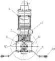
图1柔性两轮自平衡机器人的机械结构主视图;Figure 1 is the front view of the mechanical structure of the flexible two-wheeled self-balancing robot;
图2柔性两轮自平衡机器人的电子元件布局示意图;Fig. 2 Schematic diagram of the electronic component layout of the flexible two-wheeled self-balancing robot;
图3柔性两轮自平衡机器人的机械结构侧视图;The mechanical structure side view of Fig. 3 flexible two-wheeled self-balancing robot;
图4柔性两轮自平衡机器人底盘的俯视图;The top view of the flexible two-wheeled self-balancing robot chassis of Fig. 4;
图5柔性两轮自平衡机器人的柔性关节结构主视图;Figure 5 is the front view of the flexible joint structure of the flexible two-wheeled self-balancing robot;
图6柔性两轮自平衡机器人的柔性关节结构侧视图;Fig. 6 is a side view of the flexible joint structure of the flexible two-wheeled self-balancing robot;
图7柔性两轮自平衡机器人的柔性关节俯视图;Figure 7 is a top view of the flexible joint of the flexible two-wheeled self-balancing robot;
图8柔性两轮自平衡机器人的电气系统连接示意图;Figure 8 is a schematic diagram of the electrical system connection of the flexible two-wheeled self-balancing robot;
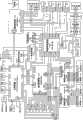
图9柔性两轮自平衡机器人的电气系统原理图;Figure 9 is a schematic diagram of the electrical system of the flexible two-wheeled self-balancing robot;
图10柔性两轮自平衡机器人的运动控制系统框图;Figure 10 is a block diagram of the motion control system of the flexible two-wheeled self-balancing robot;
图11主控制器监控软件串口接收消息处理函数流程图;Figure 11 is a flow chart of the main controller monitoring software serial port receiving message processing function;
图12主控制器监控软件定时器消息处理函数流程图;Figure 12 master controller monitoring software timer message processing function flow chart;
图13运动控制器主程序流程图;Figure 13 motion controller main program flow chart;
图14运动控制器定时中断控制程序流程图;Figure 14 motion controller timing interrupt control program flow chart;
图15运动控制器SCI接收中断程序流程图;Figure 15 motion controller SCI receiving interrupt program flow chart;
图16柔性两轮自平衡机器人的速度控制仿真曲线;Fig. 16 The speed control simulation curve of the flexible two-wheeled self-balancing robot;
图17柔性两轮自平衡机器人速度控制中姿态角变化仿真曲线;Fig. 17 The simulation curve of the attitude angle change in the speed control of the flexible two-wheeled self-balancing robot;
图18辅助控制器超声波测距控制函数流程图;Figure 18 Auxiliary controller ultrasonic ranging control function flow chart;
图19辅助控制器遥控指令检测控制函数流程图;Fig. 19 Auxiliary controller remote command detection control function flow chart;
图20辅助控制器主程序流程图。Figure 20 is the main program flow chart of the auxiliary controller.
具体实施方式Detailed ways
下面结合附图,介绍本实施例。Below in conjunction with accompanying drawing, introduce this embodiment.
一、柔性两轮自平衡机器人的硬件1. The hardware of the flexible two-wheeled self-balancing robot
1.电气系统选型1. Electrical system selection
主控制器1选用研祥嵌入式计算机(EPC)EC5-1717CLDNA。该系统是一款采用Intel915GM芯片组的高性能单板电脑,板载1.6GHz Pentium M处理器,256MB D DR II 533内存,集成显卡、声卡,提供各种接口。EPC的硬盘存储器38为东芝抗震硬盘MK4036GAC,存储容量40GB,工作中可抗最大2.0G振动及200G瞬时冲击。The
运动控制器2选用飓风公司MSK2812系统板。该系统的处理器采用TI公司TMS320F2812DSP,系统为5V直流供电。The
MSK2812的仿真器39选用飓风公司的XDS510USB,USB2.0接口。The
辅助控制器3选用凌阳科技公司的SPCE061A系统板,系统为5V直流供电,处理器为16位u′nSPTM微控制器,板载麦克风36,可实现语音识别功能。
伺服驱动器4选用Copley Motion公司的AJC55-18。AJC55-18可用于位置,转速和扭矩控制,外部控制器可以通过模拟方式(±10V,扭矩,速度,位置),PWM(扭矩,速度),以及极性PWM方式(扭矩,速度)对目标电机进行伺服控制。AJC55-18可通过串口与PC系统通信,设定工作模式和控制器参数。
液晶显示屏17选用台湾友达光电公司的B084SN0,3.3v供电,分辨率800*600。接口包括LVDS端口,背光灯电源线。液晶显示屏的背光升压板(40)选用三菱公司的T511024.04,5V直流供电。The liquid
扬声器37选用一对功率为2W的无源扬声器单元。The
倾角仪15、18选用Crossbow公司的CXTA-01。它主要采用高稳定性的硅微机械电容倾角传感器,以模拟信号方式输出倾斜角度。CXTA-01的测量范围为±75°,分辨率为0.05°,带宽为125Hz,8-30V直流供电,输出电压0-5V,零位电压2.5V。The
陀螺仪16、19选用Silicon Sensing Systems Japan公司的CRS03。CRS03角速度传感器基于MEMS技术制造,在剧烈冲击和震动条件下仍能保持卓越的性能,温漂小并具有良好的重复性,主要参数为:量程±100°/s,直流5V供电,零位电压2.5V,测量分辨率20mV/°/s,带宽为10Hz。The
选用四个Parallax公司的PING)))超声波传感器17组成的阵列作为避障传感器。PING)))为5V直流供电,具有一个超声波发射模块和一个接受模块,通过测量超声波脉冲遇到物体反射后的回波传播时间来测量距离。PING)))的测量范围2cm-3m,分辨率<1cm。An array of four PING)))
机器人视觉传感器选用USB接口CMOS摄像头12,130万像素。The robot vision sensor uses a USB
遥控系统包括遥控器33和遥控接收器27,分别为3V和5V直流供电,遥控距离20米。遥控器33有12个按键,当有键按下时,遥控接收器27的4个IO口将输出不同的电平组合。The remote control system includes a remote control 33 and a
机器人的驱动电机5选用Maxon公司的直流电机RE40套件,电机为24V供电,额定功率150W,配备26∶1的行星齿轮减速器,最大输出转矩7.5Nm,电机后端配有增量式光电编码器20,精度为1000线。The driving
机器人的电源为24V 9Ah镍氢充电电池28。29为电源继电器板,OP-DC01上的电压转换模块将24V直流输入转为5V直流输出,用于相关设备供电。定制直流24V输入的ATX电源适配器41,输出ATX/AT接口电源,为主控制器1、硬盘存储器38、背光升压板40供电。电源监控板30OP-DY01上的单片机在检测到电压低于22.5V时,控制蜂鸣器报警。The power supply of the robot is 24V 9Ah Ni-MH
2.机械结构与电气元件布局2. Mechanical structure and electrical component layout
本实施例总重量20kg,高度700mm,宽度400mm,长度150mm,轮子直径250mm。机器人的机械结构和电器元件布局如下:The present embodiment has a total weight of 20kg, a height of 700mm, a width of 400mm, a length of 150mm, and a wheel diameter of 250mm. The mechanical structure and electrical component layout of the robot are as follows:
如图1、2、3所示,躯干部分6为铝合金框架,分为上、中、下三层。躯干6的上层为前后敞口的中空屉框,内部固定主控制器1,顶板11之上通过中空的圆柱形支架42固定摄像头12。躯干6的中层由平行底面的三块亚格力隔板14隔为四小层,其中,最上一层安装硬盘存储器38、辅助控制器3和遥控接收器27,第二层安装ATX电源适配器41,第三层安装电源继电器板29和电源监控板30,第四层安装背光升压板40。躯干的中层的四周装有亚格力面板,用以保护内部电子元件以及防止中间隔板14脱落,其中前面板43上固定着液晶显示屏34和扬声器37。躯干的下层为前后敞口的中空屉框,内部装载倾角仪15和陀螺仪16。底层框架前端固定一个面朝前的带状支架44,用于安装四个超声波传感器17。As shown in Figures 1, 2 and 3, the
躯干底板13和底盘8顶端面之间以柔性俯仰关节7连接。柔性关节7的结构如图5、6、7所示:顶端和底端为上、下支承圆盘22、23,剖面为“凸”字形,圆盘中心开通孔用于电线穿过。在上支撑圆盘凸台面上,以沉头螺钉45固定上支座46。上支座46的方形底板中央开通孔,与支撑圆盘通孔孔径相同,装配时两孔同心。上支座46的底板两侧有竖起的圆顶角剑头形支座壁,其上开有同心的通孔。在下支撑圆盘23的相同位置以相同方式安装下支座47,下支座47与上支座46不同的是其两个侧壁均为双层,令上支座46侧壁可插入间隙紧密配合,另外,下支座壁47的通孔直径略小。上支座46两侧壁上的通孔中分别插入铜套48后与下支座47的侧壁通孔直径相同,上、下支座46、47装配时两侧壁通孔同心,在其中分别插入转动轴24,并以挡板49固定,使得上、下支承圆盘22、23能够以转动轴24为铰接点转动。两个转动轴24外侧各穿过一个双臂扭簧25,扭簧25的上臂固定在上支承圆盘22的卡槽中,扭簧的下臂末端的圆勾通过螺栓50固定在下支座47的侧壁上。在上、下支座46、47装配时,上、下支撑圆盘22、23之间压紧固定一段圆柱弹簧26,其两端分别套在上、下支撑圆盘22、23的凸台外。The
如图2、4所示,机器人的底盘部分8为铝合金制箱式结构。在底盘左右两侧的中心位置各装有一组轴系,主要包括转轴51、轴承52、轴承座53等。在底盘8内部中间位置,左右轮电机5前后错开固定在齿轮传动箱54外,电机的轴通过传动齿轮55与轴系的转轴51联接。使用螺栓56将轴系的转轴53与轴辖57连接,两者之间夹持固定轮子10。在底盘8内,运动控制器2和仿真器39安装在前侧,电机伺服控制器4安装在后侧,倾角仪18、陀螺仪19和电池28安装在底部。底盘8底面有两个可拆卸保护支架9,支架末端的脚轮21在机器人直立时悬空,倾倒时脚轮21触地起到支撑保护作用。As shown in Figures 2 and 4, the
3.电气系统连接3. Electrical system connection
如图8所示,电气系统各部分的连接方法如下:As shown in Figure 8, the connection method of each part of the electrical system is as follows:
EC5-1717CLDNA与硬盘存储器38连接组成主控制器1;在EC5-1717CLDNA面板接口FP1的1、2脚之间串入触点开关58作为它的启动按钮。ATX电源适配器41连接EC5-1717CLDNA为其供电。EC5-1717CLDNA is connected with the
EC5-1717CLDNA的四个RS232串口COM1、COM2、COM3、COM4分别与MSK2812、SPCE061A、两个ACJ55-18的串口连接。此外,EC5-1717CLDNA通过USB接口连接DSP的仿真器39XDS510USB,仿真器39再与DSP的JTAG接口连接。The four RS232 serial ports COM1, COM2, COM3 and COM4 of EC5-1717CLDNA are respectively connected to the serial ports of MSK2812, SPCE061A and two ACJ55-18. In addition, EC5-1717CLDNA is connected to DSP emulator 39XDS510USB through USB interface, and
EC5-1717CLDNA的USB1接口与摄像头12连接,SPK接口与扬声器37连接,LVDS接口与液晶显示屏34连接。背光升压板40的一端连接液晶显示屏34的背光灯电源线,另一端的1、2、3、4线与ATX电源适配器41的直流5V输出连接,5、6线与ATX电源适配器41的GND相连。The USB1 interface of the EC5-1717CLDNA is connected with the
另外,在机器人停止运动时,EC5-1717CLDNA可以连接键盘31、鼠标32和显示器35,进行程序编写与调试。In addition, when the robot stops moving, the EC5-1717CLDNA can be connected to the
MSK2812板由电源继电器板29的+5V输出供电,它的J7接口的38,37,36,35脚,即A/D转换输入通道,分别与两个倾角仪(CXTA01)15、18和两个陀螺仪(CRS03)16、19的模拟信号输出端连接;两个陀螺仪16、19分别由MSK2812的J7接口的1和7脚,即+5V输出供电;倾角仪15、18则由电源继电器板的24V输出直接供电。The MSK2812 board is powered by the +5V output of the
MSK2812与两个伺服控制器(AJC55-18)4间的连接包括控制信号线和编码器反馈信号线。控制信号包括电机使能信号、电机转动方向信号和PWM转速控制量信号。其中,MSK2812的J5接口的3、7脚分别与控制左、右电机的AJC55-18的J5接口的3脚连接,作为AJC55-18的使能信号线;MSK2812的J5接口的5、1脚分别与控制左、右电机的AJC55-18的J5接口的6脚连接,作为电机5转动方向选择信号线;MSK2812的J7接口17、18脚为PWM输出,分别与控制左、右电机5的(AJC55-18)4的J5接口的20脚连接,作为转速控制量信号线。左、右电机编码器20的反馈信号经AJC55-18缓存后连接至MSK2812,具体接线为左、右电机AJC55-18的J5接口的10、11脚,分别接MSK2812的J7接口的27、28脚和J6接口的13、14脚。The connection between MSK2812 and two servo controllers (AJC55-18) 4 includes control signal lines and encoder feedback signal lines. The control signal includes a motor enable signal, a motor rotation direction signal and a PWM speed control signal. Among them, pins 3 and 7 of the J5 interface of MSK2812 are respectively connected to
两个AJC55-18的J3接口的3、4脚为电源输入端,分别接电源继电器板29的+24V和GND;J2接口的3、4脚为控制电压的输出端,分别与电机的+/-输入端连接,其中3脚与电机+输入端之间串接一个电机开关59;J4接口的4、6分别为+5V和GND,分别与编码器20排线的2、3线连接,J4接口的1、8、2、9、3、10脚为编码器A通道、B通道和零位信号的共模输入端,分别接编码器排线的5、6、7、8、9、10线。
SPCE061A由电源继电器板29的+5V输出供电,它的J1接口的2~5针,分别连接超声波传感器17,1#~4#的Signal端;J2接口2~5针,分别连接遥控接收器27的输出D0~D3。SPCE061A is powered by the +5V output of the
两组24V4.5Ah的镍氢电池组并联组成24V9Ah电池28。电池28经一个双刀双掷的船型开关60分别与电源继电器板29和充电器插口61连接。当船型开关60从“关”拨到“开”时,电池给开始供电,拨到“充电”时,外接直流充电器62为电池充电。Two sets of 24V4.5Ah Ni-MH battery packs are connected in parallel to form a
电源继电器板29的+/-输入端连接电池组28的+/-端,提供24V和5V两种直流输出,分别连接各对应设备的供电端。The +/- input terminal of the
电源监控板30的Vd、GND和Vin分别接电源继电器板29的+5V、GND和+24V。Vd, GND and Vin of the
4.电气系统的工作原理4. How the electrical system works
本实施例机器人的主要功能是在保持机身俯仰姿态平衡的前提下,能够进行行走、转弯等运动,这种运动可以是机器人按照行为决策规则自主智能行为,也可以是按照用户即时下达的操作指令运动。由此,机器人电气系统的工作原理如图9所示:机器人的主控制器1经串口从运动控制器2和辅助控制器3读取各个传感器反馈信息和遥控操作指令并在液晶屏34上显示,然后按照运动行为决策算法计算出机器人的运动控制命令,并通过串口下达给运动控制器2;运动控制器2由模数转换模块得到倾角仪15、18、陀螺仪16、19的反馈信号,经过伺服驱动器4中继读取编码器20反馈信号,然后,综合接收到得控制命令和反馈信号,按预定的运动平衡控制算法计算出电机的转矩控制量,发送对应的PWM信号给伺服驱动器4执行;伺服驱动器4控制电机5运动,电机5带动轮子10使机器人维持机身平衡以及按主控制器1控制命令运动。The main function of the robot in this embodiment is to be able to perform movements such as walking and turning under the premise of maintaining the balance of the pitching attitude of the fuselage. command movement. Thus, the working principle of the robot electrical system is as shown in Figure 9: the
二、机器人系统的运动控制方法Second, the motion control method of the robot system
本实施例给出柔性两轮自平衡机器人自主避障和遥控操作两种运动模式控制系统的软件实现,其他如机器人智能行为决策、语音操作等控制功能可以参考本实施例软件,添加相应模块进行设计。This embodiment provides the software implementation of the two motion control systems of the flexible two-wheeled self-balancing robot autonomous obstacle avoidance and remote control operation. Other control functions such as robot intelligent behavior decision-making and voice operation can refer to the software of this embodiment and add corresponding modules to implement design.
图10为控制系统的框图,功能为实现机器人的两种运动模式,一为自主避障运动模式,二为遥控操作运动模式。其中,运动模式通过遥控器按键选择;机器人的运动以动作集合描述,包含:前进、后退、左转弯、右转弯、静止和左、右原地旋转;通过控制机器人的直行速度Vx和偏航速度ωα来完成动作,控制命令如下表所示:Figure 10 is a block diagram of the control system, which functions to realize two motion modes of the robot, one is the autonomous obstacle avoidance motion mode, and the other is the remote control operation motion mode. Among them, the movement mode is selected by the remote control button; the movement of the robot is described by a set of actions, including: forward, backward, left turn, right turn, stationary and left and right in situ rotation; by controlling the straight speed Vx and yaw of the robot Speed ωα to complete the action, the control command is shown in the following table:
表中v的值取0.1m/s,D为两轮轮心距,取0.4m。The value of v in the table is 0.1m/s, and D is the wheel center distance between the two wheels, which is 0.4m.
整个控制系统由四部分软件实现,分别运行在主控制器1、运动控制器2、辅助控制器3和伺服驱动控制器4中。The entire control system is implemented by four parts of software, which run in the
1.主控制器1中的监控程序1. The monitoring program in the
主控制器1中的监控程序RobotControl.exe为Windows系统应用程序,采用Visual C++软件开发。该程序可实时监测遥控命令(遥控输入键值Rc)与机器人运行状态(直线速度Vx、旋转角速度ωα、底盘和躯干的姿态角θ1和θ2、姿态角速度

串口通信的内容为主控制器1向运动控制器2下达控制命令,以及运动控制器2和辅助控制器3向主控制器1上传机器人状态信息。通信方式为异步串行通信,通信协议为:串口传输波特率19200,每帧8位数据位,无奇偶校验,1个停止位。主控制器1下达给运动控制器2的控制命令数据包的格式为:<F0h,F0h,V,数据,W,数据,数据包长度值,FFh,FFh>。其中,数据包长度值为整型变量,字符“V”代表机器人直行速度控制命令Vxc,字符“W”代表机器人偏航速度控制命令ωc,“数据”为他们对应的浮点型变量值。The content of the serial port communication is that the
主控制器1接收的状态信息数据包的格式为:<F0h,F0h,数据代码,数据,数据代码,数据,......,数据包长度值,FFh,FFh>。其中,数据包长度值为整型变量,数据代码与其对应的数据名称如下表所示:The format of the status information packet received by the

表中除Rc以外其他数据类型均为浮点型,Rc为遥控指令代码,代码的值及其对应遥控器按键和所定义功能如下表所示:The other data types in the table except Rc are floating-point types, and Rc is the remote control command code. The value of the code and its corresponding remote control button and defined function are shown in the following table:
本例采用开源的串口类CSerial实现串口操作,相关代码和说明可在http://codegure.earthweb.com/network/serialpot.shtml下载。In this example, the open source serial port class CSerial is used to realize the serial port operation. The relevant code and instructions can be downloaded at http://codegure.earthweb.com/network/serialpot.shtml.
图10中标出机器人运动行为决策控制的框图,其具体算法为:运动发生器查询当前运行模式参数值(缺省为遥控操作模式),若为自主避障运行模式,则查询最新的超声波测距值,依照预置的行为规则表选择动作,若为遥控操作模式,则程序查询遥控输入指令直接从运动集合中选择相应的动作(缺省动作为静止);随后将选定动作对应的期望直行和偏航速度控制命令Vxd、ωαd输出到决策器;决策器读取最近10次接收的底盘和躯干的姿态角θ1和θ2、姿态角速度

其中,机器人自主避障运行模式的行为规则与超声波传感器17反馈的障碍物距离信息直接相关,具体为下表所示:Among them, the behavior rules of the autonomous obstacle avoidance operation mode of the robot are directly related to the obstacle distance information fed back by the
表中S1-S4代表机器人身前从左至右的四个超声波传感器17,当S1所测距离值DS1小于1米时,S1=1,否则S1=0,S2-S4同理赋值。In the table, S1-S4 represent the four
监控程序的流程为:程序启动后,主线程初始化串口COM1、COM2(主要设定波特率19200、8位数据位、无奇偶校验、1位停止位、缓冲区512字节等),创建并启动它们各自的串口监测线程,设置1000ms定时器Timer,最后在无限循环中处理消息队列中消息。当COM1或COM2收到一个字节时,串口监测线程将该字节以消息方式传递给主线程,主线程响应该消息后运行对应的消息处理函数OnCommunication1或OnCommunication2(程序流程如图11所示),函数中将收到的字节读入缓冲区,判断此字节是否为数据包结尾,若否,退出消息处理函数,若是,则校验该数据包长度值是否正确,若不正确,则放弃该数据包,清空缓冲区,退出消息处理函数,若正确,则按串口通信协议解析该数据包,取出状态数据保存至存储区,更新视窗中对应的显示信息,清空缓冲区,退出消息处理函数。Timer计时满1000ms向主线程发送消息,主线程响应该消息后运行消息处理函数OnTimer(程序流程如图12所示),函数中读取存储区用户指令和机器人的状态信息,根据运动行为决策算法计算出控制命令Vxc、ωαc;如果控制命令与上一次定时程序计算结果不同,则通过串口COM1向运动控制器(2)发送新的控制命令后退出函数,若相同,则直接退出函数。The process of the monitoring program is: after the program starts, the main thread initializes the serial ports COM1 and COM2 (mainly setting the baud rate to 19200, 8 data bits, no parity, 1 stop bit, buffer 512 bytes, etc.), and creates And start their respective serial port monitoring threads, set the 1000ms timer Timer, and finally process the messages in the message queue in an infinite loop. When COM1 or COM2 receives a byte, the serial port monitoring thread sends the byte to the main thread in the form of a message, and the main thread runs the corresponding message processing function OnCommunication1 or OnCommunication2 after responding to the message (the program flow is shown in Figure 11) , the function reads the received byte into the buffer, and judges whether the byte is the end of the data packet. If not, exit the message processing function. If so, check whether the length value of the data packet is correct. If not, then Abandon the data packet, clear the buffer, and exit the message processing function. If it is correct, analyze the data packet according to the serial communication protocol, take out the state data and save it to the storage area, update the corresponding display information in the window, clear the buffer, and exit message processing function. The timer sends a message to the main thread when the timer reaches 1000ms, and the main thread runs the message processing function OnTimer after responding to the message (the program flow is shown in Figure 12). Calculate the control command Vxc , ωαc ; if the control command is different from the calculation result of the last timing program, send a new control command to the motion controller (2) through the serial port COM1 and exit the function, if they are the same, exit the function directly function.
2.运动控制器2中的控制软件2. Control software in
运动控制器2的程序采用TI公司的CCS软件开发,并固化在存储单元中。程序以SCI接收中断的方式接收主控制器1控制命令,以25ms定时中断的方式实现机器人姿态平衡和运动的实时控制,并在每次定时中断后向主控制器1发送状态数据。其中,定时中断的优先级高于SCI接收中断优先级。本实施例给出主程序和中断程序的算法流程,涉及到DSP的资源配置、使用,串口的接收、发送的操作等的具体实现,可直接参考TI公司为TMS320F2812DSP提供的例程。The program of the
主程序流程如图13所示:首先进行必要的初始化,完成程序使用的变量的初始化和配置DSP各寄存器状态,主要配置控制中所需的IO端口和A/D通道、通用定时器T1-T4(设置并开启T1为中断周期计时器,T2、T4为编码器的计数器,T3为PWM信号输出的比较计时器)、SCI(设定波特率19200、8位数据位、无奇偶校验、1位停止位、使能收发FIFO缓冲等)。然后,开启PWM输出,向伺服驱动器发送使能信号;接着,使能SCI接收端口RX、T1定时中断、SCI接收中断;最后,进行无限循环等待中断到来,在每次循环中,判断定时中断程序运行标志变量Flag是否为1,若否则无操作,若是则将θ1、

当SCI的接收FIFO缓存收到一个字节时产生中断,CPU响应该中断后,保存当前程序现场,转入SCI接收中断程序。如图14,SCI接收中断程序的流程为:首先,关闭SCI接收中断;第二步,从接收FIFO缓存中读取一个字节;第三步,判断该字节是否为数据包末尾,若否,存储该字节,返回第二步读取下一个字节,若是,则判断该数据包长度是否正确,若不正确,则放弃该数据包,执行下一步,若正确,则解析该数据包数据,取出Vxc和ωαc的数值并存储;第四步,清空接收FIFO缓存;最后,打开SCI中断,退出中断程序。When the receiving FIFO buffer of SCI receives a byte, an interrupt is generated. After the CPU responds to the interrupt, it saves the current program site and transfers to the SCI receiving interrupt program. As shown in Figure 14, the flow of the SCI receive interrupt program is: first, close the SCI receive interrupt; second, read a byte from the receive FIFO buffer; third, determine whether the byte is the end of the data packet, if not , store the byte, return to the second step to read the next byte, if yes, judge whether the length of the data packet is correct, if not, discard the data packet, go to the next step, if correct, parse the data packet Data, take out the values of Vxc and ωαc and store them; the fourth step is to clear the receiving FIFO buffer; finally, open the SCI interrupt and exit the interrupt program.
每当T1计时满25ms时产生中断,DSP响应该中断,保存当前程序现场,转入定时中断程序。如图15所示,定时中断程序的流程为:Whenever T1 is over 25ms, an interrupt is generated, and DSP responds to the interrupt, saves the current program scene, and transfers to the regular interrupt program. As shown in Figure 15, the flow of the timer interrupt program is:
Step1:关闭定时器T1中断。Step1: Turn off timer T1 interrupt.
Step2:获取编码器信息。每个编码器输出信号为两组正交编码序列,DSP中的正交编码脉冲电路对这两组信号的上升沿和下降沿均进行计数,因此产生的时钟频率是每组输入序列的四倍,所以读取通用定时器T2、T4的计数器数值后,需除以四才能得到一个周期内编码器输出的脉冲数nl,nr。Step2: Obtain encoder information. Each encoder output signal is two sets of orthogonal encoding sequences, and the orthogonal encoding pulse circuit in DSP counts the rising and falling edges of these two sets of signals, so the clock frequency generated is four times that of each set of input sequences , so after reading the counter values of the general timers T2 and T4, it needs to be divided by four to get the number of pulses nl and nr output by the encoder in one cycle.
Step3:计算机器人的累积直线位移、累积偏航角度、直线速度和偏航角速度。由编码器信息可知一周期内每个轮子转过的角度


Step4:按照底盘的倾角仪18、陀螺仪19,躯干的倾角仪15、陀螺仪16的顺序,对它们输出的模拟电压信号分别进行A/D转换。为避免采样过程中偶然因素的影响,每个信号均连续采样10次,进行A/D转换,去掉其中最大值和最小值后求均值赋给对应的变量:
Step5:计算底盘和躯干的倾斜角度和倾斜角速度。通过公式:

Step6:以控制命令Vxc、ωαc为参考输入,以检测到的x、Vx、α、ωα、θ1、

Step7:刷新输出至伺服驱动器的PWM占空比和电机转动方向。Step7: Refresh the PWM duty cycle and motor rotation direction output to the servo drive.
Step8:设置计时器T1,重新开始25ms计时,设置T2、T4,重新开始计数。Step8: Set timer T1, restart 25ms timing, set T2, T4, restart counting.
Step9:开T1中断,退出中断程序。Step9: Turn on T1 interrupt and exit the interrupt program.
Step6中提到的运动平衡控制算法为:如图10所示,直行速度控制器K1根据姿态零位误差和直行速度误差计算出直线速度控制量u1,偏航速度控制器K2根据偏航速度误差计算出的偏航速度控制量u2,[u1 u2]T左乘耦合矩阵D计算出电机控制转矩[τ1 τ2]T;直行速度控制器和偏航速度控制器的设计选用线性二次型最优控制算法:The motion balance control algorithm mentioned in
首先,将机器人的线性状态方程分解为直行运动和偏航运动两个单输入子系统。根据机器人的机械系统的特点和参数,建立其数学模型,在直立平衡点线性化获得线性状态空间方程:First, the linear state equation of the robot is decomposed into two single-input subsystems, the straight motion and the yaw motion. According to the characteristics and parameters of the mechanical system of the robot, its mathematical model is established, and the linear state space equation is obtained by linearizing at the upright balance point:
其中,
可得直行运动子系统的状态方程:The state equation of the straight-going motion subsystem can be obtained:
其中,
可得偏航运动子系统的状态方程:The state equation of the yaw motion subsystem can be obtained:
其中,
u1、u2与u的关系为:
其次,通过求得直行运动子系统与偏航运动子系统的能控性矩阵均满秩,证明两者完全能控,系统各状态值又均可测量获得,因此以Vxc、ωαc分别为两个子系统参考输入,状态X1、X2为反馈量,构造如图10中标出的运动平衡控制系统,并采用线性二次型最优控制方法设计两个子系统的状态反馈控制器:Secondly, by obtaining the full rank of the controllability matrices of the straight motion subsystem and the yaw motion subsystem, it is proved that the two are completely controllable, and each state value of the system can be measured. Therefore, Vxc , ωαc are the reference inputs of the two subsystems, and the states X1 and X2 are the feedback quantities, construct the motion balance control system marked in Figure 10, and use the linear quadratic optimal control method to design the state feedback controllers of the two subsystems:
定义两个子系统的性能指标:Define the performance metrics for the two subsystems:

其中Q1=diag[1 100 100 100 10 10]、Q2=diag[1 1]为状态变量的加权矩阵,R1=R2=1为控制量的加权系数。通过Matlab程序的函数K=lqr(A,B,Q,R)可求得反馈控制律u1*=-K1X1,u2*=-K2X2,分别使得性能指标极小。Wherein Q1 =diag[1 100 100 100 10 10], Q2 =diag[1 1] are the weighting matrix of the state variable, and R1 =R2 =1 is the weighting coefficient of the control variable. Through the function K=lqr(A, B, Q, R) of the Matlab program, the feedback control law u1* =-K1 X1 , u2* =-K2 X2 can be obtained, respectively making the performance index extremely small.
K1=[-2.2361 -137.7072 35.3820 -23.769 -14.9711 -8.8326]K1 =[-2.2361-137.7072 35.3820-23.769-14.9711-8.8326]
K2=[2.2361 22.3755]K2 =[2.2361 22.3755]
机器人跟踪脉宽直线、旋转速度信号的曲线如图16所示。图17中曲线为调速过程中机器人底盘、躯干部分倾角的变化。The curves of the robot tracking the pulse width straight line and the rotation speed signal are shown in Figure 16. The curve in Fig. 17 is the variation of the inclination angle of the chassis and trunk of the robot during the speed regulation process.
3.辅助控制3中的软件3. Software in
辅助控制器3的软件在凌阳公司的μ’nSPTM集成开发环境中编写,通过串口下载并固化到它的存储器中。软件的功能是控制超声波传感器17测距,检测遥控输入指令,并将结果发送给主控制器1。其工作流程如图20所示:程序开始时先进行必要的初始化,如完成程序中各个变量的初始化,设置串口、IO端口和定时器TimerA参数等;然后开始无限循环,每次循环中按照超声波传感器的编号顺序,循环调用GetDistance函数,控制超声波传感器测量与前方障碍物的距离并存储,待4个传感器均测量完毕,将所有测量结果按照通信协议通过串口发送给组织级EPC。在两个超声波传感器工作的间歇,调用GetRemoteKey函数读取遥控接收器的信息,根据返回结果更新遥控器指令代码,并按照通信协议经串口发至组织级EPC。The software of the
如图18所示,GetRemoteKey函数的流程为:设置IOA低八位为输入,将IOA低八位输入值存储至Key_temp变量,延时10ms,将IOA低八位输入值与Key_temp比较,若相同,则说明遥控按键确实触发,返回Key_temp值,若不同,则说明遥控按键没有触发,返回Null。As shown in Figure 18, the process of the GetRemoteKey function is: set the lower eight bits of IOA as input, store the input value of the lower eight bits of IOA in the Key_temp variable, delay 10ms, compare the input value of the lower eight bits of IOA with Key_temp, if they are the same, It means that the remote control key is indeed triggered, and the value of Key_temp is returned. If it is different, it means that the remote control key is not triggered, and Null is returned.
如图19所示,GetDistance函数的流程为:设置IOA高八位为输出,向第i号超声波传感器对应的IO引脚IOA.i发送一个5us脉冲;设置IOA为高八位为输入,等待IOA.i有上升沿到来,启动计时器TimerA;当IOA.i下降沿到来,停止计时,读取计时数据赋给变量SonarTime,按照公式Distance=(SonarTime*0.01050917)/2计算出测距结果并返回。As shown in Figure 19, the process of the GetDistance function is: set the high eight bits of IOA as output, send a 5us pulse to the IO pin IOA.i corresponding to the i-th ultrasonic sensor; set IOA as high eight bits as input, and wait for IOA When .i has a rising edge, start the timer TimerA; when the falling edge of IOA.i arrives, stop timing, read the timing data and assign it to the variable SonarTime, calculate the distance measurement result according to the formula Distance=(SonarTime*0.01050917)/2 and return .
4.伺服驱动器4的软件4. Software of
在AJC55-18配套PC端软件COPLEY MOTION2中,通过输入直流电机(5)参数能够自动计算伺服程序的比例积分(PI)调节参数,简单设置控制系统结构后即可自动生成伺服控制程序,并通过串口下载固化至AJC55-18的存储单元中。该伺服程序控制周期1ms,以DSP输出的PWM信号和转向信号分别为电机参考转矩和参考转向,取电枢电流为负反馈,实现电机转矩PI伺服控制。In the AJC55-18 supporting PC software COPLEY MOTION2, the proportional integral (PI) adjustment parameters of the servo program can be automatically calculated by inputting the parameters of the DC motor (5), and the servo control program can be automatically generated after simply setting the control system structure, and passed The serial port download is solidified into the storage unit of AJC55-18. The servo program has a control cycle of 1 ms. The PWM signal and the steering signal output by the DSP are the reference torque and the reference steering of the motor respectively, and the armature current is used as negative feedback to realize the PI servo control of the motor torque.
三、机器人系统的使用3. The use of robotic systems
使用本实施例的机器人时,可按如下步骤操作:When using the robot of this embodiment, it can be operated as follows:
1.确认机器人的电气系统连接正确,为机器人连接鼠标32。1. Confirm that the electrical system of the robot is connected correctly, and connect the mouse 32 to the robot.
2.将主电源的船型开关60拨至“开”。2. Turn the
3.按下触点开关58启动主控制器1EC5-1717CLDNA。3. Press the
4.运行RobotControl.exe。4. Run RobotControl.exe.
5.断开鼠标32,将机器人扶稳至直立位置。5. Disconnect the mouse 32 and stabilize the robot to an upright position.
6.打开电机开关59,机器人开始平衡控制。6. Turn on the
7.待机器人在直立位置上稳定后,不再扶持。7. After the robot is stable in the upright position, no longer support it.
8.通过遥控器33按钮选择机器人运行模式或动作指令操作机器人运动。8. Use the button 33 on the remote control to select the robot operation mode or the action command to operate the robot movement.
9.停机时,通过遥控器33令机器人静止,扶稳机器人后依次关闭电机开关59、RobotControl.exe、EC5-1717CLDNA、主电源船型开关60。9. When shutting down, use the remote controller 33 to make the robot still, and then turn off the
Claims (9)
Translated fromChinesePriority Applications (3)
| Application Number | Priority Date | Filing Date | Title |
|---|---|---|---|
| CN2009100842598ACN101554726B (en) | 2009-05-15 | 2009-05-15 | A flexible two-wheel self-balancing robot system and its motion control method |
| PCT/CN2010/072271WO2010130179A1 (en) | 2009-05-15 | 2010-04-28 | Flexible two-wheel self-balance robot system and motion control method thereof |
| US12/770,328US8321053B2 (en) | 2009-05-15 | 2010-04-29 | Flexible two-wheeled self-balancing robot system and its motion control method |
Applications Claiming Priority (1)
| Application Number | Priority Date | Filing Date | Title |
|---|---|---|---|
| CN2009100842598ACN101554726B (en) | 2009-05-15 | 2009-05-15 | A flexible two-wheel self-balancing robot system and its motion control method |
Publications (2)
| Publication Number | Publication Date |
|---|---|
| CN101554726Atrue CN101554726A (en) | 2009-10-14 |
| CN101554726B CN101554726B (en) | 2011-01-19 |
Family
ID=41173084
Family Applications (1)
| Application Number | Title | Priority Date | Filing Date |
|---|---|---|---|
| CN2009100842598AExpired - Fee RelatedCN101554726B (en) | 2009-05-15 | 2009-05-15 | A flexible two-wheel self-balancing robot system and its motion control method |
Country Status (3)
| Country | Link |
|---|---|
| US (1) | US8321053B2 (en) |
| CN (1) | CN101554726B (en) |
| WO (1) | WO2010130179A1 (en) |
Cited By (50)
| Publication number | Priority date | Publication date | Assignee | Title |
|---|---|---|---|---|
| WO2010130179A1 (en)* | 2009-05-15 | 2010-11-18 | 北京工业大学 | Flexible two-wheel self-balance robot system and motion control method thereof |
| CN101791800B (en)* | 2010-01-21 | 2011-05-25 | 西北工业大学 | A motion control method for a two-wheel differential robot |
| CN102749845A (en)* | 2012-06-15 | 2012-10-24 | 华中科技大学 | Electric system state feedback controller construction method based on event trigger mechanism |
| CN102779444A (en)* | 2012-06-29 | 2012-11-14 | 四川大学 | Plastic model wandering in driving school yard |
| CN102945000A (en)* | 2012-11-29 | 2013-02-27 | 北京理工大学 | Observability constraint-based random planet landing track optimizing method |
| CN103257605A (en)* | 2013-04-12 | 2013-08-21 | 苏州欧泰克电子科技有限公司 | Two-wheel self-balancing driving system based on embedded ARM |
| CN103753557A (en)* | 2014-02-14 | 2014-04-30 | 上海创绘机器人科技有限公司 | Self-balance control method of movable type inverted pendulum system and self-balance vehicle intelligent control system |
| CN103778843A (en)* | 2012-10-25 | 2014-05-07 | 西安航天精密机电研究所 | Industrial robot demonstration and reappearance method |
| CN103970020A (en)* | 2014-05-21 | 2014-08-06 | 北京航空航天大学 | Mobile robot system and coordination control method of mobile robot system in hybrid interaction environment |
| CN104020699A (en)* | 2014-05-30 | 2014-09-03 | 哈尔滨工程大学 | Movable type visual identification material sorting intelligent robot controlling apparatus |
| CN104070527A (en)* | 2014-07-15 | 2014-10-01 | 广州大学 | Ball field ball picking robot |
| CN104216409A (en)* | 2014-09-04 | 2014-12-17 | 北京工业大学 | Two-wheeled self-balancing robot obstacle avoidance system and control method based on fuzzy control |
| CN104375506A (en)* | 2014-11-29 | 2015-02-25 | 江西洪都航空工业集团有限责任公司 | Robot-orientated embedded type intelligent mobile controller |
| TWI503640B (en)* | 2014-03-26 | 2015-10-11 | Univ Kun Shan | Method for supervisory fuzzy control of inverted pendulum cart |
| CN105116729A (en)* | 2015-08-17 | 2015-12-02 | 杭州电子科技大学 | A self-adaptive sliding mode variable structure control method and system for a two-wheeled self-balancing robot |
| CN105148496A (en)* | 2015-09-08 | 2015-12-16 | 华中科技大学 | Posture control-based roller skating type mobility robot |
| CN105563453A (en)* | 2016-03-08 | 2016-05-11 | 大连理工大学 | A two-wheeled autonomous mobile platform with a spring-driven robotic arm |
| CN105818670A (en)* | 2016-05-30 | 2016-08-03 | 昆山穿山甲机器人有限公司 | Elastic damping chassis structure of wheeled robot |
| CN105911879A (en)* | 2015-11-13 | 2016-08-31 | 中国人民解放军装甲兵工程学院 | Frame type inverted robot development platform |
| CN106128173A (en)* | 2016-08-24 | 2016-11-16 | 玉林市民族中学 | A kind of teaching robot |
| CN106313022A (en)* | 2016-10-31 | 2017-01-11 | 苏州立源信智能科技有限公司 | Safety protection truss robot |
| CN106527469A (en)* | 2016-12-29 | 2017-03-22 | 新奥(中国)燃气投资有限公司 | Interactive intelligent robot control system, control method and interactive intelligent robot |
| CN106926912A (en)* | 2017-03-23 | 2017-07-07 | 西北师范大学 | A kind of magnetic force distribution absorption type three-wheel climbing robot |
| CN107097241A (en)* | 2017-06-05 | 2017-08-29 | 江苏艾萨克机器人股份有限公司 | A kind of service robot and its control method |
| WO2017143569A1 (en)* | 2016-02-25 | 2017-08-31 | 深圳市创客工场科技有限公司 | Smart robot |
| CN107172348A (en)* | 2017-05-16 | 2017-09-15 | 奇酷互联网络科技(深圳)有限公司 | The distribution method and device of mobile terminal and its motor message |
| CN107323194A (en)* | 2017-08-16 | 2017-11-07 | 苏州索亚机器人技术有限公司 | A kind of mobile robot for installing suspended shock absorbing mechanism additional |
| CN107685325A (en)* | 2016-08-10 | 2018-02-13 | 北京小米移动软件有限公司 | Self-balance robot and its speed control unit and method for control speed |
| CN107728285A (en)* | 2017-10-26 | 2018-02-23 | 信利光电股份有限公司 | A kind of camera module |
| CN107885215A (en)* | 2017-11-22 | 2018-04-06 | 南京航空航天大学 | A kind of two-wheeled wireless remote controlled intelligent dolly |
| CN107953332A (en)* | 2017-12-12 | 2018-04-24 | 石化盈科信息技术有限责任公司 | A kind of drive control panel of anti-riot robot |
| CN108181878A (en)* | 2018-01-04 | 2018-06-19 | 江苏科瑞恩自动化科技有限公司 | A kind of kinetic control system for the equipment containing vision system |
| CN108332833A (en)* | 2018-02-07 | 2018-07-27 | 钱立文 | A film roll weight reading and transmission system |
| CN108356789A (en)* | 2017-05-19 | 2018-08-03 | 重庆交通大学 | supermarket shopping intelligent robot |
| CN108436875A (en)* | 2018-02-11 | 2018-08-24 | 坎德拉(深圳)科技创新有限公司 | Robot |
| CN108638077A (en)* | 2018-06-27 | 2018-10-12 | 天津商业大学 | A kind of robot teaching handle |
| CN109213174A (en)* | 2018-10-24 | 2019-01-15 | 北京工业大学 | A kind of sewage treatment plant's intelligent patrol detection barrier-avoiding method based on fuzzy neural network |
| CN109343346A (en)* | 2018-10-09 | 2019-02-15 | 浙江工业大学 | A method for automatic obstacle avoidance of self-balancing vehicle based on fuzzy control |
| CN109545068A (en)* | 2019-01-30 | 2019-03-29 | 宁波市镇海大来智能科技有限公司 | A kind of teaching robot's suit |
| CN109693747A (en)* | 2017-10-20 | 2019-04-30 | 深圳市亮点智控科技有限公司 | A kind of swing type balanced robot and balanced robot's control method |
| CN109732623A (en)* | 2019-03-06 | 2019-05-10 | 陈敏 | A kind of robot of accompanying and attending to painted |
| CN110390810A (en)* | 2019-07-25 | 2019-10-29 | 中国科学院合肥物质科学研究院 | A remote control and remote control method for a high-mobility ground unmanned platform |
| CN111070220A (en)* | 2019-12-18 | 2020-04-28 | 南京驭逡通信科技有限公司 | Detection robot with telescopic partial limbs |
| CN111309016A (en)* | 2020-02-26 | 2020-06-19 | 腾讯科技(深圳)有限公司 | Self-balancing robot control system, self-balancing robot control method, self-balancing robot and medium |
| CN111665838A (en)* | 2020-05-21 | 2020-09-15 | 浙江工业大学 | Attitude control method for self-balancing robot to resist continuous external force action |
| CN112809708A (en)* | 2021-02-26 | 2021-05-18 | 共享智能铸造产业创新中心有限公司 | Handle operating means and robot |
| CN112917514A (en)* | 2021-01-20 | 2021-06-08 | 云南电网有限责任公司电力科学研究院 | Cable temperature detection device based on snake-shaped robot |
| CN113305844A (en)* | 2021-05-28 | 2021-08-27 | 深圳市优必选科技股份有限公司 | Humanoid robot balance control method and device and humanoid robot |
| CN113843790A (en)* | 2021-09-13 | 2021-12-28 | 歌尔科技有限公司 | Robot, method for controlling robot, and readable storage medium |
| CN118849037A (en)* | 2024-09-24 | 2024-10-29 | 北京海百川科技有限公司 | An intelligent autonomous mobile service robot |
Families Citing this family (59)
| Publication number | Priority date | Publication date | Assignee | Title |
|---|---|---|---|---|
| US9020639B2 (en) | 2009-08-06 | 2015-04-28 | The Regents Of The University Of California | Multimodal dynamic robotic systems |
| CN102529574B (en)* | 2010-12-28 | 2015-12-16 | Ge医疗系统环球技术有限公司 | Electromagnetic torque balancing friction caster wheel of movable-type medical equipment |
| WO2013134067A1 (en)* | 2012-03-06 | 2013-09-12 | Trw Automotive U.S. Llc | Method and apparatus for diagnosing inertia sensor |
| US8783394B1 (en) | 2012-05-10 | 2014-07-22 | T3 Motion, Inc. | Drive wheel suspension |
| DE202012005170U1 (en)* | 2012-05-25 | 2012-07-11 | Abb Ag | Mobile motion and camera terrain |
| CN102798448B (en)* | 2012-09-06 | 2015-02-04 | 上海新世纪机器人有限公司 | Online load detection device for self-balancing two-wheel vehicle |
| USD701796S1 (en)* | 2012-10-03 | 2014-04-01 | T3 Motion, Inc. | Wheel suspension and drive system |
| CN103223673B (en)* | 2013-05-21 | 2015-10-28 | 重庆电子工程职业学院 | The control method of leg-wheel robot |
| GB2506726B (en)* | 2013-07-16 | 2014-10-22 | Sergey Nikolaevich Andreev | Two-wheel gyroscope-stabilized vehicle and methods for controlling thereof |
| CN103559347B (en)* | 2013-10-31 | 2016-04-06 | 浙江大学 | A kind of construction method of extensive AC and DC power system electromagnetic transient simulation model |
| WO2015081455A1 (en)* | 2013-12-02 | 2015-06-11 | Mi Robotic Solutions S.A. | Robotised and/or remote-controlled machine for removing and inserting switchgear equipment, comprising a chassis, wheels, a support, a structure, a camera, and controls, and method for same |
| USD733203S1 (en) | 2013-12-17 | 2015-06-30 | Roambotics Inc. | Personal robot |
| RU2564796C2 (en)* | 2014-01-13 | 2015-10-10 | Научно-исследовательская лаборатория автоматизации проектирования, общество с ограниченной ответственностью (НИЛ АП, ООО) | Wheeled robot chassis |
| FR3020843A1 (en)* | 2014-05-09 | 2015-11-13 | Aldebaran Robotics | CONNECTION ASSEMBLY BETWEEN TWO PIECES CONNECTED BY AN ARTICULATION |
| JP6254930B2 (en)* | 2014-12-10 | 2017-12-27 | ファナック株式会社 | Gear gripping apparatus and method for gripping gears |
| CN104724233A (en)* | 2015-01-28 | 2015-06-24 | 西南大学 | Directly-driven two-wheeled self-balancing electric vehicle |
| WO2016130565A1 (en) | 2015-02-09 | 2016-08-18 | The Regents Of The University Of California | Ball-balancing robot and drive assembly therefor |
| CN104848851B (en)* | 2015-05-29 | 2017-08-18 | 山东鲁能智能技术有限公司 | Substation inspection robot and its method based on multi-sensor data fusion composition |
| KR102419489B1 (en)* | 2015-07-13 | 2022-07-12 | 현대모비스 주식회사 | Apparatus and method for measuring speed of motor |
| CN105047062B (en)* | 2015-08-03 | 2017-11-03 | 北京工业大学 | A kind of Axially moving belt makees the experimental provision of oscillation crosswise under simple boundary |
| CN105116894A (en)* | 2015-08-24 | 2015-12-02 | 铜陵学院 | Double-core high-speed two-wheeled picomouse full digital navigation servo controller, and control method thereof |
| US10065667B2 (en)* | 2016-07-26 | 2018-09-04 | Soken, Inc. | Carrier apparatus |
| CN106355988B (en)* | 2016-09-22 | 2020-02-07 | 佛山华数机器人有限公司 | Multifunctional training robot |
| US10493617B1 (en) | 2016-10-21 | 2019-12-03 | X Development Llc | Robot control |
| JP6549654B2 (en)* | 2017-08-03 | 2019-07-24 | ファナック株式会社 | Robot system simulation apparatus and simulation method |
| CN107450480B (en)* | 2017-08-06 | 2019-08-16 | 苏州镁伽智能制造科技有限公司 | Control device, control method, medium and the system of moving component |
| CN107643760A (en)* | 2017-08-24 | 2018-01-30 | 齐鲁工业大学 | A kind of coaxial two wheels robot balance controller based on LQR algorithms |
| CN107679302A (en)* | 2017-09-21 | 2018-02-09 | 北京众绘虚拟现实技术研究院有限公司 | A kind of continuous deformation restoration methods based on the analysis of inverse finite element optimization |
| CN108356829B (en)* | 2017-12-14 | 2023-08-15 | 河北汇金集团股份有限公司 | Two-wheeled self-balancing guiding robot |
| US10776194B2 (en)* | 2018-01-31 | 2020-09-15 | Splunk Inc. | Self-monitor for computing devices of a distributed computing system |
| CN108161889B (en)* | 2018-02-08 | 2023-11-24 | 北京华航唯实机器人科技股份有限公司 | Industrial robot based on AGV |
| CN113568344B (en)* | 2018-03-15 | 2022-12-06 | 北京骑胜科技有限公司 | Method and system for controlling bicycle based on pressure detection |
| US11055423B2 (en)* | 2018-03-30 | 2021-07-06 | Infineon Technologies Ag | Signal pattern checksum |
| CN108582111A (en)* | 2018-05-31 | 2018-09-28 | 中瑞福宁机器人(沈阳)有限公司 | People can be replaced remotely to see the robot of vehicle |
| CN109011535B (en)* | 2018-09-28 | 2023-12-29 | 大连理工大学 | Automatic pendulum robot that receives of portable snooker |
| CN108919732B (en)* | 2018-10-18 | 2024-12-27 | 无疆(武汉)技术有限公司 | A control box for robot execution drive |
| GB2578903B (en)* | 2018-11-13 | 2021-08-25 | Arrival Ltd | Two wheel automatic guided vehicles |
| CN109492318B (en)* | 2018-11-22 | 2023-04-07 | 北京师范大学珠海分校 | Mechanical power system of self-balance running bicycle and multi-rigid-body dynamic model thereof |
| CN109545066B (en)* | 2018-12-21 | 2024-02-13 | 洛阳豪特现代测试技术有限公司 | Gear drive comprehensive experiment device |
| CN110181540A (en)* | 2019-07-09 | 2019-08-30 | 民政部一零一研究所 | All directionally movable robot |
| CN110673621A (en)* | 2019-10-24 | 2020-01-10 | 电子科技大学 | Two-wheeled self-balancing trolley control system |
| WO2021133105A1 (en)* | 2019-12-24 | 2021-07-01 | 삼성전자주식회사 | Mobile robot device and control method therefor |
| CN111230885B (en)* | 2020-03-03 | 2023-05-23 | 中山早稻田科技有限公司 | Intelligent cooperative robot control system, method and storage medium |
| CN112001042A (en)* | 2020-07-23 | 2020-11-27 | 山东电力设备有限公司 | Hardware system design method and hardware system of transformer detection robot |
| CN112256035B (en)* | 2020-11-03 | 2023-08-15 | 浙江国自机器人技术股份有限公司 | Chassis drift control method, system and device and AGV trolley |
| CN112578712B (en)* | 2020-12-15 | 2023-10-13 | 天津城建大学 | Two-wheeled robot motion and control method |
| CN113140006B (en)* | 2021-04-30 | 2023-01-20 | 中德(珠海)人工智能研究院有限公司 | Control method and system of self-balancing robot and storage medium |
| CN113184077B (en)* | 2021-06-09 | 2022-07-22 | 曾嘉禹 | Smart task type biped robot based on SLAM and machine vision and control method thereof |
| CN113952743A (en)* | 2021-11-08 | 2022-01-21 | 张小杰 | Educational robot intelligent control system based on open source hardware |
| CN114089668B (en)* | 2021-11-22 | 2023-11-07 | 大连理工大学 | An integrated mobile robot distributed control method |
| CN114179432B (en)* | 2021-12-10 | 2024-04-19 | 重庆江东机械有限责任公司 | Full-automatic multi-station hydraulic press demolding control system and control method |
| CN114280997B (en)* | 2021-12-29 | 2024-05-24 | 东北电力大学 | Microgravity environment simulation operation training system and control method thereof |
| CN114393580A (en)* | 2022-01-16 | 2022-04-26 | 西安石油大学 | Four-DOF multi-control mode handling manipulator based on STM32 |
| CN114475676A (en)* | 2022-03-02 | 2022-05-13 | 昆山燎原自动化设备有限责任公司 | RGV dolly and charging system for train chassis detects |
| CN114537554B (en)* | 2022-03-07 | 2023-03-21 | 电子科技大学成都学院 | Coal mine safety searching tool car |
| CN114740719B (en)* | 2022-03-28 | 2023-05-23 | 台州学院 | Self-balancing control method of inverted pendulum system based on linear matrix inequality |
| CN116373614A (en)* | 2023-03-24 | 2023-07-04 | 华南师范大学 | Self-balancing control method for two-wheeled robot and robot |
| CN116852392A (en)* | 2023-07-13 | 2023-10-10 | 兰州理工大学 | A remote-controlled traffic command robot |
| CN117773928B (en)* | 2023-12-26 | 2024-08-02 | 上海木蚁机器人科技有限公司 | Mobile device calibration method and device, electronic device and storage medium |
Family Cites Families (17)
| Publication number | Priority date | Publication date | Assignee | Title |
|---|---|---|---|---|
| US5350033A (en)* | 1993-04-26 | 1994-09-27 | Kraft Brett W | Robotic inspection vehicle |
| US6473713B1 (en)* | 1999-09-20 | 2002-10-29 | American Gnc Corporation | Processing method for motion measurement |
| JP3555107B2 (en)* | 1999-11-24 | 2004-08-18 | ソニー株式会社 | Legged mobile robot and operation control method for legged mobile robot |
| JP2006136962A (en)* | 2004-11-11 | 2006-06-01 | Hitachi Ltd | Mobile robot |
| JP4886201B2 (en)* | 2005-03-14 | 2012-02-29 | 株式会社日立製作所 | Mobile robot |
| US7789175B2 (en)* | 2005-10-11 | 2010-09-07 | Cycogs, Llc | Modular dual wheel drive assembly, wheeled devices that include modular dual wheel drive assemblies and methods for moving and/or maneuvering wheeled devices using modular dual wheel drive assemblies |
| CN100511326C (en)* | 2005-10-18 | 2009-07-08 | 中国科学技术大学 | Inverted pendulum of remote car with two wheels and balance control method thereof |
| TWI290881B (en)* | 2005-12-26 | 2007-12-11 | Ind Tech Res Inst | Mobile robot platform and method for sensing movement of the same |
| JP4291822B2 (en)* | 2006-02-03 | 2009-07-08 | トヨタ自動車株式会社 | Inverted wheel type traveling body |
| CN201000695Y (en)* | 2007-01-19 | 2008-01-02 | 北京工业大学 | A flexible two-wheel upright robot body |
| CN201035817Y (en)* | 2007-04-27 | 2008-03-12 | 北京工业大学 | Trolley inverted pendulum with adjustable center of gravity |
| CN100491083C (en)* | 2007-07-27 | 2009-05-27 | 北京工业大学 | Attitude detection method of flexible two-wheeled self-balancing robot |
| JP2009101817A (en)* | 2007-10-23 | 2009-05-14 | Toyota Motor Corp | Inverted wheel type moving body and control method thereof |
| JP2009101897A (en)* | 2007-10-24 | 2009-05-14 | Toyota Motor Corp | Inverted wheel type moving body and control method thereof |
| JP2009101898A (en)* | 2007-10-24 | 2009-05-14 | Toyota Motor Corp | Inverted wheel type moving body and control method thereof |
| CN101554726B (en)* | 2009-05-15 | 2011-01-19 | 北京工业大学 | A flexible two-wheel self-balancing robot system and its motion control method |
| CN201525024U (en)* | 2009-05-15 | 2010-07-14 | 北京工业大学 | A flexible two-wheel self-balancing robot |
- 2009
- 2009-05-15CNCN2009100842598Apatent/CN101554726B/ennot_activeExpired - Fee Related
- 2010
- 2010-04-28WOPCT/CN2010/072271patent/WO2010130179A1/enactiveApplication Filing
- 2010-04-29USUS12/770,328patent/US8321053B2/ennot_activeExpired - Fee Related
Cited By (63)
| Publication number | Priority date | Publication date | Assignee | Title |
|---|---|---|---|---|
| WO2010130179A1 (en)* | 2009-05-15 | 2010-11-18 | 北京工业大学 | Flexible two-wheel self-balance robot system and motion control method thereof |
| CN101791800B (en)* | 2010-01-21 | 2011-05-25 | 西北工业大学 | A motion control method for a two-wheel differential robot |
| CN102749845A (en)* | 2012-06-15 | 2012-10-24 | 华中科技大学 | Electric system state feedback controller construction method based on event trigger mechanism |
| CN102779444A (en)* | 2012-06-29 | 2012-11-14 | 四川大学 | Plastic model wandering in driving school yard |
| CN103778843B (en)* | 2012-10-25 | 2017-02-15 | 西安航天精密机电研究所 | Industrial robot demonstration and reappearance method |
| CN103778843A (en)* | 2012-10-25 | 2014-05-07 | 西安航天精密机电研究所 | Industrial robot demonstration and reappearance method |
| CN102945000A (en)* | 2012-11-29 | 2013-02-27 | 北京理工大学 | Observability constraint-based random planet landing track optimizing method |
| CN102945000B (en)* | 2012-11-29 | 2016-06-01 | 北京理工大学 | Based on the planet landing trajectory random optimization method of observability constraint |
| CN103257605A (en)* | 2013-04-12 | 2013-08-21 | 苏州欧泰克电子科技有限公司 | Two-wheel self-balancing driving system based on embedded ARM |
| CN103753557A (en)* | 2014-02-14 | 2014-04-30 | 上海创绘机器人科技有限公司 | Self-balance control method of movable type inverted pendulum system and self-balance vehicle intelligent control system |
| TWI503640B (en)* | 2014-03-26 | 2015-10-11 | Univ Kun Shan | Method for supervisory fuzzy control of inverted pendulum cart |
| CN103970020A (en)* | 2014-05-21 | 2014-08-06 | 北京航空航天大学 | Mobile robot system and coordination control method of mobile robot system in hybrid interaction environment |
| CN103970020B (en)* | 2014-05-21 | 2016-08-31 | 北京航空航天大学 | Mobile-robot system and the control method for coordinating under mixing interactive environment thereof |
| CN104020699A (en)* | 2014-05-30 | 2014-09-03 | 哈尔滨工程大学 | Movable type visual identification material sorting intelligent robot controlling apparatus |
| CN104070527A (en)* | 2014-07-15 | 2014-10-01 | 广州大学 | Ball field ball picking robot |
| CN104216409A (en)* | 2014-09-04 | 2014-12-17 | 北京工业大学 | Two-wheeled self-balancing robot obstacle avoidance system and control method based on fuzzy control |
| CN104375506A (en)* | 2014-11-29 | 2015-02-25 | 江西洪都航空工业集团有限责任公司 | Robot-orientated embedded type intelligent mobile controller |
| CN105116729A (en)* | 2015-08-17 | 2015-12-02 | 杭州电子科技大学 | A self-adaptive sliding mode variable structure control method and system for a two-wheeled self-balancing robot |
| CN107368081A (en)* | 2015-08-17 | 2017-11-21 | 杭州电子科技大学 | A kind of double-wheel self-balancing robot adaptive sliding mode variable structure control system |
| CN105116729B (en)* | 2015-08-17 | 2017-11-07 | 杭州电子科技大学 | A self-adaptive sliding mode variable structure control method for a two-wheeled self-balancing robot |
| CN105148496A (en)* | 2015-09-08 | 2015-12-16 | 华中科技大学 | Posture control-based roller skating type mobility robot |
| CN105911879A (en)* | 2015-11-13 | 2016-08-31 | 中国人民解放军装甲兵工程学院 | Frame type inverted robot development platform |
| WO2017143569A1 (en)* | 2016-02-25 | 2017-08-31 | 深圳市创客工场科技有限公司 | Smart robot |
| CN105563453A (en)* | 2016-03-08 | 2016-05-11 | 大连理工大学 | A two-wheeled autonomous mobile platform with a spring-driven robotic arm |
| CN105818670A (en)* | 2016-05-30 | 2016-08-03 | 昆山穿山甲机器人有限公司 | Elastic damping chassis structure of wheeled robot |
| CN107685325B (en)* | 2016-08-10 | 2020-04-03 | 北京小米移动软件有限公司 | Self-balancing robot and its speed control device and speed control method |
| CN107685325A (en)* | 2016-08-10 | 2018-02-13 | 北京小米移动软件有限公司 | Self-balance robot and its speed control unit and method for control speed |
| CN106128173A (en)* | 2016-08-24 | 2016-11-16 | 玉林市民族中学 | A kind of teaching robot |
| CN106313022A (en)* | 2016-10-31 | 2017-01-11 | 苏州立源信智能科技有限公司 | Safety protection truss robot |
| CN106527469A (en)* | 2016-12-29 | 2017-03-22 | 新奥(中国)燃气投资有限公司 | Interactive intelligent robot control system, control method and interactive intelligent robot |
| CN106926912A (en)* | 2017-03-23 | 2017-07-07 | 西北师范大学 | A kind of magnetic force distribution absorption type three-wheel climbing robot |
| CN107172348B (en)* | 2017-05-16 | 2020-03-27 | 奇酷互联网络科技(深圳)有限公司 | Mobile terminal and distribution method and device of motion signals of mobile terminal |
| CN107172348A (en)* | 2017-05-16 | 2017-09-15 | 奇酷互联网络科技(深圳)有限公司 | The distribution method and device of mobile terminal and its motor message |
| CN108356789A (en)* | 2017-05-19 | 2018-08-03 | 重庆交通大学 | supermarket shopping intelligent robot |
| CN107097241A (en)* | 2017-06-05 | 2017-08-29 | 江苏艾萨克机器人股份有限公司 | A kind of service robot and its control method |
| CN107323194A (en)* | 2017-08-16 | 2017-11-07 | 苏州索亚机器人技术有限公司 | A kind of mobile robot for installing suspended shock absorbing mechanism additional |
| CN109693747A (en)* | 2017-10-20 | 2019-04-30 | 深圳市亮点智控科技有限公司 | A kind of swing type balanced robot and balanced robot's control method |
| CN107728285A (en)* | 2017-10-26 | 2018-02-23 | 信利光电股份有限公司 | A kind of camera module |
| CN107885215A (en)* | 2017-11-22 | 2018-04-06 | 南京航空航天大学 | A kind of two-wheeled wireless remote controlled intelligent dolly |
| CN107953332A (en)* | 2017-12-12 | 2018-04-24 | 石化盈科信息技术有限责任公司 | A kind of drive control panel of anti-riot robot |
| CN108181878A (en)* | 2018-01-04 | 2018-06-19 | 江苏科瑞恩自动化科技有限公司 | A kind of kinetic control system for the equipment containing vision system |
| CN108332833A (en)* | 2018-02-07 | 2018-07-27 | 钱立文 | A film roll weight reading and transmission system |
| CN108332833B (en)* | 2018-02-07 | 2020-01-03 | 钱立文 | Film roll weight reading and transmission system |
| CN108436875A (en)* | 2018-02-11 | 2018-08-24 | 坎德拉(深圳)科技创新有限公司 | Robot |
| CN108638077A (en)* | 2018-06-27 | 2018-10-12 | 天津商业大学 | A kind of robot teaching handle |
| CN109343346A (en)* | 2018-10-09 | 2019-02-15 | 浙江工业大学 | A method for automatic obstacle avoidance of self-balancing vehicle based on fuzzy control |
| CN109213174A (en)* | 2018-10-24 | 2019-01-15 | 北京工业大学 | A kind of sewage treatment plant's intelligent patrol detection barrier-avoiding method based on fuzzy neural network |
| CN109213174B (en)* | 2018-10-24 | 2021-10-01 | 北京工业大学 | An intelligent inspection and obstacle avoidance method for sewage treatment plant based on fuzzy neural network |
| CN109545068A (en)* | 2019-01-30 | 2019-03-29 | 宁波市镇海大来智能科技有限公司 | A kind of teaching robot's suit |
| CN109732623A (en)* | 2019-03-06 | 2019-05-10 | 陈敏 | A kind of robot of accompanying and attending to painted |
| CN110390810B (en)* | 2019-07-25 | 2020-11-17 | 中国科学院合肥物质科学研究院 | Remote controller of high-mobility ground unmanned platform and remote control method thereof |
| CN110390810A (en)* | 2019-07-25 | 2019-10-29 | 中国科学院合肥物质科学研究院 | A remote control and remote control method for a high-mobility ground unmanned platform |
| CN111070220A (en)* | 2019-12-18 | 2020-04-28 | 南京驭逡通信科技有限公司 | Detection robot with telescopic partial limbs |
| CN111309016A (en)* | 2020-02-26 | 2020-06-19 | 腾讯科技(深圳)有限公司 | Self-balancing robot control system, self-balancing robot control method, self-balancing robot and medium |
| CN111665838A (en)* | 2020-05-21 | 2020-09-15 | 浙江工业大学 | Attitude control method for self-balancing robot to resist continuous external force action |
| CN111665838B (en)* | 2020-05-21 | 2023-08-29 | 浙江工业大学 | Gesture control method for self-balancing robot to resist continuous external force action |
| CN112917514A (en)* | 2021-01-20 | 2021-06-08 | 云南电网有限责任公司电力科学研究院 | Cable temperature detection device based on snake-shaped robot |
| CN112809708A (en)* | 2021-02-26 | 2021-05-18 | 共享智能铸造产业创新中心有限公司 | Handle operating means and robot |
| CN113305844A (en)* | 2021-05-28 | 2021-08-27 | 深圳市优必选科技股份有限公司 | Humanoid robot balance control method and device and humanoid robot |
| CN113305844B (en)* | 2021-05-28 | 2022-09-09 | 深圳市优必选科技股份有限公司 | Humanoid robot balance control method and device and humanoid robot |
| CN113843790A (en)* | 2021-09-13 | 2021-12-28 | 歌尔科技有限公司 | Robot, method for controlling robot, and readable storage medium |
| CN118849037A (en)* | 2024-09-24 | 2024-10-29 | 北京海百川科技有限公司 | An intelligent autonomous mobile service robot |
| CN118849037B (en)* | 2024-09-24 | 2024-11-29 | 北京海百川科技有限公司 | An intelligent autonomous mobile service robot |
Also Published As
| Publication number | Publication date |
|---|---|
| CN101554726B (en) | 2011-01-19 |
| US8321053B2 (en) | 2012-11-27 |
| US20100292840A1 (en) | 2010-11-18 |
| WO2010130179A1 (en) | 2010-11-18 |
Similar Documents
| Publication | Publication Date | Title |
|---|---|---|
| CN101554726B (en) | A flexible two-wheel self-balancing robot system and its motion control method | |
| CN101590323B (en) | One-wheel robot system and its control method | |
| CN101623865A (en) | One-wheel robot system and control method thereof | |
| CN201525024U (en) | A flexible two-wheel self-balancing robot | |
| CN102445944B (en) | A self-balancing robot system with one wheel | |
| CN100511326C (en) | Inverted pendulum of remote car with two wheels and balance control method thereof | |
| CN102815357B (en) | Self-balancing manned solowheel based on inertia balance wheel | |
| CN100442185C (en) | A multi-modal biomimetic robotic fish | |
| CN101850548B (en) | Inverted pendulum balancing control system based on flywheel | |
| CN106057056A (en) | Teaching robot dolly based on STM32F4 microcontroller | |
| CN110109354B (en) | Self-adaptive sliding mode control method for counteractive wheel balance bicycle robot | |
| CN114080301A (en) | Independently translating coaxial robotic arm and sensing housing | |
| CN201565951U (en) | Single wheel robot system | |
| CN116719231A (en) | Two-wheeled robot and its control method, device and storage medium | |
| CN201525025U (en) | A unicycle robot system | |
| Dai et al. | Development of a coaxial self-balancing robot based on sliding mode control | |
| CN210589256U (en) | Miniature humanoid two-wheeled self-balancing robot | |
| Tompa et al. | Remote control and monitoring of an autonomous mobile robot | |
| Lamon | The solero rover | |
| Santos et al. | Engineering solutions to build an inexpensive humanoid robot based on a distributed control architecture | |
| CN201674326U (en) | A Balance Control System of Inverted Pendulum Based on Flywheel | |
| Bonci et al. | Embedded system for a Ballbot robot | |
| Firlej | Design, construction and control of a spherical rolling robot with internal two-wheel cart | |
| CN213862463U (en) | Double-wheel balance jumping all-terrain reconnaissance trolley | |
| Tóth et al. | Control systems in omni-directional robotic vehicle with mecanum wheels |
Legal Events
| Date | Code | Title | Description |
|---|---|---|---|
| C06 | Publication | ||
| PB01 | Publication | ||
| C10 | Entry into substantive examination | ||
| SE01 | Entry into force of request for substantive examination | ||
| C14 | Grant of patent or utility model | ||
| GR01 | Patent grant | ||
| CF01 | Termination of patent right due to non-payment of annual fee | ||
| CF01 | Termination of patent right due to non-payment of annual fee | Granted publication date:20110119 |