CN101554683A - Laser oscillator and laser processing apparatus - Google Patents
Laser oscillator and laser processing apparatusDownload PDFInfo
- Publication number
- CN101554683A CN101554683ACNA200910129884XACN200910129884ACN101554683ACN 101554683 ACN101554683 ACN 101554683ACN A200910129884X ACNA200910129884X ACN A200910129884XACN 200910129884 ACN200910129884 ACN 200910129884ACN 101554683 ACN101554683 ACN 101554683A
- Authority
- CN
- China
- Prior art keywords
- laser
- optical
- laser beam
- higher hamonic
- mirror
- Prior art date
- Legal status (The legal status is an assumption and is not a legal conclusion. Google has not performed a legal analysis and makes no representation as to the accuracy of the status listed.)
- Pending
Links
- 238000012545processingMethods0.000titleabstractdescription32
- 230000003287optical effectEffects0.000claimsabstractdescription159
- 239000013078crystalSubstances0.000claimsabstractdescription46
- 238000000926separation methodMethods0.000claimsabstractdescription19
- 238000000034methodMethods0.000claimsdescription9
- 239000013307optical fiberSubstances0.000claimsdescription8
- 238000005259measurementMethods0.000claimsdescription7
- 230000008569processEffects0.000claimsdescription7
- 230000005855radiationEffects0.000claimsdescription4
- 238000005086pumpingMethods0.000claimsdescription3
- 230000000295complement effectEffects0.000claims1
- 238000000605extractionMethods0.000claims1
- 230000001105regulatory effectEffects0.000claims1
- 238000006243chemical reactionMethods0.000abstractdescription8
- 230000005284excitationEffects0.000description25
- 230000010355oscillationEffects0.000description15
- 230000005540biological transmissionEffects0.000description8
- 230000000052comparative effectEffects0.000description6
- 230000007246mechanismEffects0.000description6
- 238000003466weldingMethods0.000description6
- RYGMFSIKBFXOCR-UHFFFAOYSA-NCopperChemical compound[Cu]RYGMFSIKBFXOCR-UHFFFAOYSA-N0.000description5
- 229910052802copperInorganic materials0.000description5
- 239000010949copperSubstances0.000description5
- PCHJSUWPFVWCPO-UHFFFAOYSA-NgoldChemical compound[Au]PCHJSUWPFVWCPO-UHFFFAOYSA-N0.000description5
- 229910052737goldInorganic materials0.000description5
- 239000010931goldSubstances0.000description5
- 238000010586diagramMethods0.000description4
- 239000000835fiberSubstances0.000description4
- 230000004913activationEffects0.000description3
- 230000006872improvementEffects0.000description3
- 230000001902propagating effectEffects0.000description3
- 238000010521absorption reactionMethods0.000description2
- 230000003321amplificationEffects0.000description2
- 238000010276constructionMethods0.000description2
- 230000008878couplingEffects0.000description2
- 238000010168coupling processMethods0.000description2
- 238000005859coupling reactionMethods0.000description2
- 230000007423decreaseEffects0.000description2
- 230000000694effectsEffects0.000description2
- 238000003199nucleic acid amplification methodMethods0.000description2
- 238000012360testing methodMethods0.000description2
- 230000003213activating effectEffects0.000description1
- 230000008859changeEffects0.000description1
- 238000007796conventional methodMethods0.000description1
- 238000011161developmentMethods0.000description1
- 238000005516engineering processMethods0.000description1
- 239000011521glassSubstances0.000description1
- 238000010330laser markingMethods0.000description1
- 230000001795light effectEffects0.000description1
- 238000003754machiningMethods0.000description1
- 229910052751metalInorganic materials0.000description1
- 239000002184metalSubstances0.000description1
- 150000002739metalsChemical class0.000description1
- 230000004044responseEffects0.000description1
- 230000000087stabilizing effectEffects0.000description1
- 230000002195synergetic effectEffects0.000description1
Images


Classifications
- H—ELECTRICITY
- H01—ELECTRIC ELEMENTS
- H01S—DEVICES USING THE PROCESS OF LIGHT AMPLIFICATION BY STIMULATED EMISSION OF RADIATION [LASER] TO AMPLIFY OR GENERATE LIGHT; DEVICES USING STIMULATED EMISSION OF ELECTROMAGNETIC RADIATION IN WAVE RANGES OTHER THAN OPTICAL
- H01S3/00—Lasers, i.e. devices using stimulated emission of electromagnetic radiation in the infrared, visible or ultraviolet wave range
- H01S3/10—Controlling the intensity, frequency, phase, polarisation or direction of the emitted radiation, e.g. switching, gating, modulating or demodulating
- H01S3/106—Controlling the intensity, frequency, phase, polarisation or direction of the emitted radiation, e.g. switching, gating, modulating or demodulating by controlling devices placed within the cavity
- H01S3/108—Controlling the intensity, frequency, phase, polarisation or direction of the emitted radiation, e.g. switching, gating, modulating or demodulating by controlling devices placed within the cavity using non-linear optical devices, e.g. exhibiting Brillouin or Raman scattering
- H01S3/109—Frequency multiplication, e.g. harmonic generation
- H—ELECTRICITY
- H01—ELECTRIC ELEMENTS
- H01S—DEVICES USING THE PROCESS OF LIGHT AMPLIFICATION BY STIMULATED EMISSION OF RADIATION [LASER] TO AMPLIFY OR GENERATE LIGHT; DEVICES USING STIMULATED EMISSION OF ELECTROMAGNETIC RADIATION IN WAVE RANGES OTHER THAN OPTICAL
- H01S3/00—Lasers, i.e. devices using stimulated emission of electromagnetic radiation in the infrared, visible or ultraviolet wave range
- H01S3/05—Construction or shape of optical resonators; Accommodation of active medium therein; Shape of active medium
- H01S3/08—Construction or shape of optical resonators or components thereof
- H01S3/08054—Passive cavity elements acting on the polarization, e.g. a polarizer for branching or walk-off compensation
- H—ELECTRICITY
- H01—ELECTRIC ELEMENTS
- H01S—DEVICES USING THE PROCESS OF LIGHT AMPLIFICATION BY STIMULATED EMISSION OF RADIATION [LASER] TO AMPLIFY OR GENERATE LIGHT; DEVICES USING STIMULATED EMISSION OF ELECTROMAGNETIC RADIATION IN WAVE RANGES OTHER THAN OPTICAL
- H01S3/00—Lasers, i.e. devices using stimulated emission of electromagnetic radiation in the infrared, visible or ultraviolet wave range
- H01S3/05—Construction or shape of optical resonators; Accommodation of active medium therein; Shape of active medium
- H01S3/08—Construction or shape of optical resonators or components thereof
- H01S3/08072—Thermal lensing or thermally induced birefringence; Compensation thereof
- H—ELECTRICITY
- H01—ELECTRIC ELEMENTS
- H01S—DEVICES USING THE PROCESS OF LIGHT AMPLIFICATION BY STIMULATED EMISSION OF RADIATION [LASER] TO AMPLIFY OR GENERATE LIGHT; DEVICES USING STIMULATED EMISSION OF ELECTROMAGNETIC RADIATION IN WAVE RANGES OTHER THAN OPTICAL
- H01S3/00—Lasers, i.e. devices using stimulated emission of electromagnetic radiation in the infrared, visible or ultraviolet wave range
- H01S3/09—Processes or apparatus for excitation, e.g. pumping
- H01S3/091—Processes or apparatus for excitation, e.g. pumping using optical pumping
- H01S3/094—Processes or apparatus for excitation, e.g. pumping using optical pumping by coherent light
- H01S3/094076—Pulsed or modulated pumping
- H—ELECTRICITY
- H01—ELECTRIC ELEMENTS
- H01S—DEVICES USING THE PROCESS OF LIGHT AMPLIFICATION BY STIMULATED EMISSION OF RADIATION [LASER] TO AMPLIFY OR GENERATE LIGHT; DEVICES USING STIMULATED EMISSION OF ELECTROMAGNETIC RADIATION IN WAVE RANGES OTHER THAN OPTICAL
- H01S3/00—Lasers, i.e. devices using stimulated emission of electromagnetic radiation in the infrared, visible or ultraviolet wave range
- H01S3/10—Controlling the intensity, frequency, phase, polarisation or direction of the emitted radiation, e.g. switching, gating, modulating or demodulating
- H01S3/102—Controlling the intensity, frequency, phase, polarisation or direction of the emitted radiation, e.g. switching, gating, modulating or demodulating by controlling the active medium, e.g. by controlling the processes or apparatus for excitation
- H01S3/1022—Controlling the intensity, frequency, phase, polarisation or direction of the emitted radiation, e.g. switching, gating, modulating or demodulating by controlling the active medium, e.g. by controlling the processes or apparatus for excitation by controlling the optical pumping
- H01S3/1024—Controlling the intensity, frequency, phase, polarisation or direction of the emitted radiation, e.g. switching, gating, modulating or demodulating by controlling the active medium, e.g. by controlling the processes or apparatus for excitation by controlling the optical pumping for pulse generation
- H—ELECTRICITY
- H01—ELECTRIC ELEMENTS
- H01S—DEVICES USING THE PROCESS OF LIGHT AMPLIFICATION BY STIMULATED EMISSION OF RADIATION [LASER] TO AMPLIFY OR GENERATE LIGHT; DEVICES USING STIMULATED EMISSION OF ELECTROMAGNETIC RADIATION IN WAVE RANGES OTHER THAN OPTICAL
- H01S3/00—Lasers, i.e. devices using stimulated emission of electromagnetic radiation in the infrared, visible or ultraviolet wave range
- H01S3/10—Controlling the intensity, frequency, phase, polarisation or direction of the emitted radiation, e.g. switching, gating, modulating or demodulating
- H01S3/13—Stabilisation of laser output parameters, e.g. frequency or amplitude
- H01S3/1305—Feedback control systems
- H—ELECTRICITY
- H01—ELECTRIC ELEMENTS
- H01S—DEVICES USING THE PROCESS OF LIGHT AMPLIFICATION BY STIMULATED EMISSION OF RADIATION [LASER] TO AMPLIFY OR GENERATE LIGHT; DEVICES USING STIMULATED EMISSION OF ELECTROMAGNETIC RADIATION IN WAVE RANGES OTHER THAN OPTICAL
- H01S3/00—Lasers, i.e. devices using stimulated emission of electromagnetic radiation in the infrared, visible or ultraviolet wave range
- H01S3/10—Controlling the intensity, frequency, phase, polarisation or direction of the emitted radiation, e.g. switching, gating, modulating or demodulating
- H01S3/13—Stabilisation of laser output parameters, e.g. frequency or amplitude
- H01S3/1306—Stabilisation of the amplitude
- H—ELECTRICITY
- H01—ELECTRIC ELEMENTS
- H01S—DEVICES USING THE PROCESS OF LIGHT AMPLIFICATION BY STIMULATED EMISSION OF RADIATION [LASER] TO AMPLIFY OR GENERATE LIGHT; DEVICES USING STIMULATED EMISSION OF ELECTROMAGNETIC RADIATION IN WAVE RANGES OTHER THAN OPTICAL
- H01S3/00—Lasers, i.e. devices using stimulated emission of electromagnetic radiation in the infrared, visible or ultraviolet wave range
- H01S3/10—Controlling the intensity, frequency, phase, polarisation or direction of the emitted radiation, e.g. switching, gating, modulating or demodulating
- H01S3/13—Stabilisation of laser output parameters, e.g. frequency or amplitude
- H01S3/131—Stabilisation of laser output parameters, e.g. frequency or amplitude by controlling the active medium, e.g. by controlling the processes or apparatus for excitation
- H01S3/1312—Stabilisation of laser output parameters, e.g. frequency or amplitude by controlling the active medium, e.g. by controlling the processes or apparatus for excitation by controlling the optical pumping
Landscapes
- Physics & Mathematics (AREA)
- Electromagnetism (AREA)
- Engineering & Computer Science (AREA)
- Plasma & Fusion (AREA)
- Optics & Photonics (AREA)
- Nonlinear Science (AREA)
- Optical Modulation, Optical Deflection, Nonlinear Optics, Optical Demodulation, Optical Logic Elements (AREA)
- Lasers (AREA)
Abstract
Translated fromChinese
Description
Translated fromChinese技术领域technical field
本发明总体上涉及一种利用高次谐波激光束进行激光加工的激光加工设备,更具体地,本发明涉及一种在光谐振器中从基波激光束产生高次谐波激光束的激光振荡器以及一种具有该激光振荡器的激光加工设备。The present invention generally relates to a laser processing device for laser processing using a high-order harmonic laser beam, and more particularly, the present invention relates to a laser for generating a high-order harmonic laser beam from a fundamental laser beam in an optical resonator An oscillator and a laser processing device with the laser oscillator.
背景技术Background technique
最近利用频率为YAG基波的频率的N倍(N表示等于或大于2的整数)的高次谐波进行加工已经得到关注。例如,已经广泛使用第二高次谐波的可见光激光器(绿色激光器)来加工金属,例如铜和金,其中第二高次谐波的波长为YAG基波波长(1064nm)的一半(532nm)。YAG第二高次谐波激光束显示出对铜和金具有良好的吸收率,从而能够以基波激光束的吸收率的4.5-20倍的吸收率对铜基或金基的工件进行加工。Processing with a higher harmonic having a frequency N times (N represents an integer equal to or greater than 2) the frequency of the YAG fundamental wave has recently attracted attention. For example, metals such as copper and gold have been processed using visible light lasers (green lasers) of the second higher harmonic wave, where the wavelength of the second higher harmonic wave is half (532 nm) of the YAG fundamental wave wavelength (1064 nm). The YAG second harmonic laser beam shows a good absorption rate for copper and gold, so that it can process copper-based or gold-based workpieces with an absorption rate 4.5-20 times that of the fundamental wave laser beam.
本申请人已经公开了日本专利申请早期公开公报No.2005-209965的激光焊接设备。根据该激光焊接设备,激活介质和非线性光学晶体(KTP晶体)在光学谐振器中的光路上排列成直线,激活介质被光学泵浦,以产生基波激光束,该基波激光束入射在(即,光学耦合到)非线性光学晶体上以产生激光束。该激光焊接设备具有反馈控制机构,该反馈控制机构使第二高次谐波激光束的输出匹配基准值或基准波形。即使光学谐振器中的单元由于与时间有关的原因而略微恶化或在光学对准方面产生位移,该反馈控制机构也能起作用以能将具有期望激光能量的第二高次谐波激光束发射到工件上。The present applicant has disclosed a laser welding apparatus of Japanese Patent Application Laid-Open Publication No. 2005-209965. According to this laser welding apparatus, an active medium and a nonlinear optical crystal (KTP crystal) are aligned on an optical path in an optical resonator, and the active medium is optically pumped to generate a fundamental-wave laser beam incident on (ie, optically coupled to) a nonlinear optical crystal to generate a laser beam. The laser welding apparatus has a feedback control mechanism that makes the output of the second higher harmonic laser beam match a reference value or a reference waveform. Even if the cells in the optical resonator are slightly deteriorated or shifted in optical alignment due to time-related reasons, the feedback control mechanism works to enable emission of the second higher harmonic laser beam with the desired laser energy onto the workpiece.
本申请人还公开了日本专利申请早期公开公报No.2004-214674的高次谐波激光设备。根据该高次谐波激光设备,光学谐振器中结合有光学透镜,该光学透镜将基波激光束会聚并发射到非线性光学晶体的一个刻面(facet)上。该高次谐波激光设备补偿了激光束的发散,以增加从基波转化为第二高次谐波的效率。The present applicant also discloses a higher harmonic laser device of Japanese Patent Application Laid-Open Publication No. 2004-214674. According to the higher harmonic laser device, an optical lens is incorporated in the optical resonator, and the optical lens converges and emits the fundamental laser beam onto one facet of the nonlinear optical crystal. The high harmonic laser device compensates the divergence of the laser beam to increase the conversion efficiency from the fundamental wave to the second high harmonic.
采用上面文献中公开的技术的传统激光加工设备对使用绿色激光器加工铜、金等激光加工场合的扩展/发展有很大贡献。但是在激光输出方面仍存在问题。具体地,当用低输入功率进行单一振荡时,振荡效率下降,这导致在精确焊接等领域中需要更高的激光输出。Conventional laser processing equipment employing the techniques disclosed in the above documents has greatly contributed to the expansion/development of laser processing applications using green lasers to process copper, gold, etc. But there are still problems with laser output. Specifically, when single oscillation is performed with low input power, the oscillation efficiency decreases, which leads to a need for higher laser output in fields such as precision welding.
用作激活介质的YAG棒在受到光学激励(激光振荡期间)发生热膨胀,从而由于所谓的热透镜效应而用作凸透镜。这使得基波激光束的输出不稳定,结果导致第二高次谐波激光束的输出不稳定。即使用功率反馈控制机构也很难补偿此类激光输出波动,这是因为,为了补偿激光输出的降低而增加激光输出使得热透镜效应的影响更加强烈。The YAG rod used as the active medium undergoes thermal expansion when optically excited (during laser oscillation), thereby acting as a convex lens due to the so-called thermal lens effect. This makes the output of the fundamental laser beam unstable, and as a result, the output of the second higher harmonic laser beam becomes unstable. Even with a power feedback control mechanism, it is difficult to compensate such laser output fluctuations because increasing the laser output to compensate for the decrease in laser output makes the influence of the thermal lens effect stronger.
发明内容Contents of the invention
为解决传统技术的上述问题构想出本发明,因此本发明的目的是提供一种实现激光振荡效率的进一步提高和高次谐波激光束的更高输出以提高加工能力的激光振荡器和激光加工设备。The present invention was conceived to solve the above-mentioned problems of the conventional technology, and therefore an object of the present invention is to provide a laser oscillator and laser processing that realize further improvement in laser oscillation efficiency and higher output of high-order harmonic laser beams to improve processing capabilities equipment.
为了实现上述目的,本发明的激光振荡器包括:光学谐振器,具有在光学上彼此相对布置的第一和第二终端镜;激活介质,设置在光学谐振器的光路上;激励单元,对激活介质进行泵浦以产生具有基本频率的基波激光束;非线性光学晶体,切割成II型相位匹配,在光学谐振器的光路上设置成接近第一终端镜,以产生频率为基波激光束的频率的N(N表示等于或大于2的整数)倍的高次谐波激光束;光学透镜,在光学谐振器的光路上设置成跨过非线性光学晶体与第一终端镜隔开约等于焦距的距离,使得光学透镜的焦点位于第一终端镜的反射表面附近;1/4波长板,在光学谐振器的光路上设置在激活介质与第二终端镜之间;以及高次谐波分离/输出镜,设置在光学谐振器的光路上,以从光学谐振器提取高次谐波激光束。In order to achieve the above object, the laser oscillator of the present invention includes: an optical resonator with first and second terminal mirrors arranged optically opposite to each other; an activation medium arranged on the optical path of the optical resonator; an excitation unit for activating The medium is pumped to generate a fundamental frequency laser beam; the nonlinear optical crystal, cut into type II phase matching, is set on the optical path of the optical resonator to be close to the first terminal mirror to generate a fundamental frequency laser beam N (N represents an integer equal to or greater than 2) times the higher harmonic laser beam of the frequency; the optical lens is arranged on the optical path of the optical resonator to straddle the nonlinear optical crystal and the first terminal mirror to be separated by approximately equal to a distance of the focal length such that the focus of the optical lens is located near the reflective surface of the first terminal mirror; a 1/4 wavelength plate disposed between the active medium and the second terminal mirror on the optical path of the optical resonator; and higher harmonic separation The /output mirror is arranged on the optical path of the optical resonator to extract the high-order harmonic laser beam from the optical resonator.
在本发明中,高次谐波激光束等同于例如具有第二高次谐波(波长为532nm)的频率、第三高次谐波(波长为266nm)的频率、或比这些频率高的频率的激光束。In the present invention, the higher harmonic laser beam is equivalent to, for example, having a frequency of the second higher harmonic (wavelength of 532 nm), a frequency of the third higher harmonic (wavelength of 266 nm), or a frequency higher than these frequencies laser beam.
在上述构造中,1/4波长板设置在光学谐振器中。这使得寻常光与非常光之间的功率比相对于切割成II型相位匹配的非线性光学晶体稳定。光学透镜的焦点被确定为位于第一终端镜的反射表面附近,光学透镜设置成跨过非线性光学晶体与第一终端镜的反射表面隔开约等于焦距的距离。这将非线性光学晶体光学地耦合成光学谐振器的基本振型,同时防止了基波长的光束在第一终端镜的反射表面处的散射损失,从而充分地限制了光学谐振器中的基波长光束,以提高基波的放大系数从而提高激光转换效率。以此方式,在光学谐振器中设置1/4波长板并将光学透镜的焦点确定为位于第一终端镜的反射表面附近,以加强基本振型与非线性光学晶体之间的光学耦合,这带来了协同效应,使高次谐波激光束产生的输出功率远远超过常规的高次谐波激光束。In the above configuration, a 1/4 wavelength plate is provided in the optical resonator. This stabilizes the power ratio between ordinary and extraordinary light relative to nonlinear optical crystals cut into type II phase matching. The focal point of the optical lens is determined to be located adjacent to the reflective surface of the first terminal mirror, the optical lens is disposed across the nonlinear optical crystal at a distance approximately equal to the focal length from the reflective surface of the first terminal mirror. This optically couples the nonlinear optical crystal into the fundamental mode shape of the optical resonator, while preventing the scattering loss of the beam at the fundamental wavelength at the reflective surface of the first terminal mirror, thereby substantially confining the fundamental wavelength in the optical resonator Beam, in order to increase the amplification factor of the fundamental wave and thus improve the laser conversion efficiency. In this way, the 1/4 wavelength plate is set in the optical resonator and the focal point of the optical lens is determined to be located near the reflective surface of the first terminal mirror to strengthen the optical coupling between the fundamental mode shape and the nonlinear optical crystal, which A synergistic effect is brought about, so that the output power generated by the high-order harmonic laser beam far exceeds that of the conventional high-order harmonic laser beam.
根据本发明的优选方面,光学透镜使从激活介质传播来的基波激光束基本上会聚为平行光,并使会聚的基波激光束通过非线性光学晶体以聚焦在焦点上。光学透镜然后将被第一终端镜反射为辐射展开光并通过非线性光学晶体传播到光学透镜的基波激光束准直成平行光。According to a preferred aspect of the present invention, the optical lens substantially converges the fundamental laser beam propagating from the active medium into parallel light, and makes the converged fundamental laser beam pass through the nonlinear optical crystal to focus on the focal point. The optical lens then collimates the fundamental laser beam, which is reflected by the first terminal mirror as radiation expansion light and propagates to the optical lens through the nonlinear optical crystal, into parallel light.
根据本发明的优选方面,光学透镜的焦点被确定为位于朝向光学透镜与第一终端镜的反射表面隔开5mm或更小(更优选地,为约2mm)的距离的位置。以此方式,适当地使光学透镜的焦点的位置从第一终端镜的反射表面朝光学透镜移位,可靠地防止了基波激光束的能量烧坏光学透镜这种不期望的现象。According to a preferred aspect of the present invention, the focal point of the optical lens is determined to be located towards a position where the optical lens is separated from the reflective surface of the first terminal mirror by a distance of 5mm or less (more preferably about 2mm). In this way, appropriately shifting the position of the focal point of the optical lens from the reflection surface of the first terminal mirror toward the optical lens reliably prevents an undesired phenomenon that the energy of the fundamental laser beam burns out the optical lens.
根据本发明的另一优选方面,高次谐波分离/输出镜设置在激活介质与光学透镜之间,使得高次谐波分离/输出镜相对于光学谐振器的光路倾斜给定角度。本发明的光学谐振器具有高次谐波分离/输出镜以及两个终端镜布置在一直线上的直线布置构造,但也可以具有这三个反射镜分别布置在三角形的三个顶点的三角形布置构造。直线布置构造中的高次谐波分离/输出镜对高次谐波是HR(高度反射)的,对基波是AR(抗反射:可透过)的。According to another preferred aspect of the present invention, the high-order harmonic separation/output mirror is arranged between the active medium and the optical lens, so that the high-order harmonic separation/output mirror is inclined at a given angle relative to the optical path of the optical resonator. The optical resonator of the present invention has a linear arrangement structure in which a higher harmonic separation/output mirror and two terminal mirrors are arranged on a straight line, but may also have a triangular arrangement in which these three mirrors are respectively arranged at three vertices of a triangle structure. The higher harmonic separation/output mirrors in the in-line configuration are HR (highly reflective) for higher harmonics and AR (anti-reflection: transparent) for fundamental waves.
本发明的激光加工设备包括:本发明的激光振荡器;和激光发射单元,所述激光发射单元将从激光振荡器的高次谐波分离/输出镜提取的高次谐波激光束会聚并发射到工件上。The laser processing equipment of the present invention includes: the laser oscillator of the present invention; and a laser emitting unit that converges and emits a high-order harmonic laser beam extracted from a high-order harmonic separation/output mirror of the laser oscillator onto the workpiece.
具有了本发明的激光振荡器,本发明的激光加工设备大大提高了利用高输出功率的高次谐波激光束进行激光加工的能力。With the laser oscillator of the present invention, the laser processing equipment of the present invention greatly improves the ability of laser processing with high output power high-order harmonic laser beams.
根据本发明的优选方面,激光加工设备还包括:反射镜,使从高次谐波分离/输出镜提取的高次谐波激光束的光路偏折给定角度;光纤,将高次谐波激光束从反射镜传输到激光发射单元;入射单元,设置在反射镜与光纤之间,该入射单元将来自反射镜的高次谐波激光束聚焦并发射到光纤的入射刻面(incident facet)上;和反射角调节机构,调节高次谐波激光束在反射镜处的反射方向。According to a preferred aspect of the present invention, the laser processing equipment also includes: a reflecting mirror, which deflects the optical path of the high-order harmonic laser beam extracted from the high-order harmonic separation/output mirror at a given angle; The beam is transmitted from the reflector to the laser emitting unit; the incident unit is arranged between the reflector and the optical fiber, and the incident unit focuses the high-order harmonic laser beam from the reflector and transmits it to the incident facet of the optical fiber. ; and a reflection angle adjustment mechanism, which adjusts the reflection direction of the high-order harmonic laser beam at the reflection mirror.
根据本发明的另一优选方面,激励单元包括:激励光产生单元,产生用于对激活介质进行光学泵浦的激励光;激光电源单元,向激励光产生单元提供用于产生激励光的电力;和控制单元,控制从激光电源单元向激励光产生单元提供的电力。当通过振荡而输出脉冲激光时,激光电源单元可具有:直流电源单元,输出直流电力;和开关元件,连接在直流电源单元与激励光产生单元之间,并且激光电源单元使开关元件在脉冲周期期间以高频进行开关操作,从而向激励光产生单元提供脉冲波形形式的电力。According to another preferred aspect of the present invention, the excitation unit includes: an excitation light generation unit that generates excitation light for optically pumping the activation medium; a laser power supply unit that provides the excitation light generation unit with power for generating excitation light; and a control unit that controls power supplied from the laser power supply unit to the excitation light generation unit. When outputting pulsed laser light by oscillation, the laser power supply unit may have: a DC power supply unit that outputs DC power; Switching is performed at a high frequency during this period, thereby supplying power in the form of a pulse waveform to the excitation light generating unit.
激光加工设备可包括反馈控制机构,该反馈控制机构具有测量高次谐波激光束的激光输出的高次谐波激光输出测量单元;以及控制单元,该控制单元控制开关元件的开关操作以使激光输出测量值与基准值或基准波形相匹配。在该情况下,如上所述,1/4波长板起到稳定由基波长光束得到的自然偏振波(S波和P波)之间的相位差和寻常光与非常光之间的功率比的作用。这允许进行线性功率反馈控制,从而使高次谐波激光束的输出更稳定且与基准值或基准波形的匹配更加准确。The laser processing apparatus may include a feedback control mechanism having a harmonic laser output measuring unit that measures a laser output of a high harmonic laser beam; and a control unit that controls switching operations of a switching element so that the laser The output measurement is matched to a reference value or reference waveform. In this case, as described above, the 1/4 wavelength plate plays the role of stabilizing the phase difference between the naturally polarized waves (S wave and P wave) obtained from the fundamental wavelength light beam and the power ratio between ordinary light and extraordinary light effect. This allows for linear power feedback control, resulting in more stable and more accurate matching of the output of the high harmonic laser beam to a reference value or waveform.
根据本发明的激光振荡器,上述构造和操作实现了激光振荡器效率和高次谐波激光束的更高输出方面的进一步提高。根据本发明的激光加工设备,上述构造和操作提高了高次谐波激光束的加工能力。According to the laser oscillator of the present invention, the above configuration and operation achieve further improvement in efficiency of the laser oscillator and higher output of the higher harmonic laser beam. According to the laser processing apparatus of the present invention, the above configuration and operation enhance the processing capability of the higher harmonic laser beam.
附图说明Description of drawings
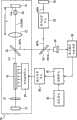
图1是根据本发明实施例的激光加工设备的构造图;Fig. 1 is a structural diagram of a laser processing device according to an embodiment of the present invention;
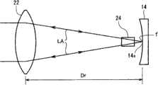
图2是所述实施例的光学谐振器中的光学透镜的构造和操作的示图;2 is a diagram of the configuration and operation of an optical lens in the optical resonator of the embodiment;
图3是比较示例的光学谐振器中的光学透镜的构造和操作的示图;3 is a diagram of the configuration and operation of an optical lens in an optical resonator of a comparative example;
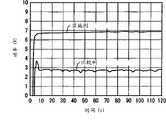
图4是示出所述实施例的激光加工设备表现出的时间/激光功率特性的示图;FIG. 4 is a graph showing time/laser power characteristics exhibited by the laser processing apparatus of the embodiment;
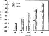
图5是示出所述实施例的激光加工设备表现出的激励电流/振荡效率特性的示图;和Fig. 5 is a graph showing excitation current/oscillation efficiency characteristics exhibited by the laser processing apparatus of the embodiment; and
图6是根据本发明另一实施例的激光加工设备的构造图。Fig. 6 is a configuration diagram of a laser processing apparatus according to another embodiment of the present invention.
具体实施方式Detailed ways
现在将参照附图描述本发明的优选实施例。Preferred embodiments of the present invention will now be described with reference to the accompanying drawings.
图1示出根据本发明实施例的激光加工设备的构造。该激光加工设备构造成利用绿色激光束(波长为532nm的第二高次谐波)以长脉冲(脉宽为10μs或更高,一般为1-3ms)的形式对主要由铜或金制成的工件W进行激光加工(例如,激光焊接)的绿色激光加工器。FIG. 1 shows the configuration of a laser processing apparatus according to an embodiment of the present invention. The laser processing equipment is constructed to use a green laser beam (the second high-order harmonic with a wavelength of 532nm) in the form of a long pulse (pulse width of 10μs or higher, generally 1-3ms) to a laser beam mainly made of copper or gold. A green laser processor for laser processing (for example, laser welding) of workpiece W.
激光加工设备的激光振荡器10包括一对终端镜12和14,直的光路位于终端镜12和14之间,该激光振荡器10还包括在终端镜12和14之间的光路上以给定间隔从左向右(图1中)排列成直线的1/4波长板16、激活介质18、高次谐波分离/输出镜20、聚光透镜22和非线性光学晶体(波长变换晶体)24。在另一构造中,反射镜可以设置在1/4波长板16与激活介质之间以使光学谐振器中的光路偏折。The
终端镜12和14彼此面对以构成光学谐振器。位于图1左侧的第二终端镜12的反射表面12a涂覆有反射基波长(1064nm)的膜。位于图1右侧的第一终端镜14的反射表面14a涂覆有反射基波长(1064nm)的膜和反射第二高次谐波(532nm)的膜。
两个终端镜12和14的反射表面12a和14a中的每个形成为具有适当曲率半径的凹表面。例如,第一终端镜14的反射表面14a具有约9000mm的曲率半径,第二终端镜12的反射表面12a具有约5000mm的曲率半径。Each of the
激活介质18由例如Nd-YAG棒制成,并接近第二终端镜12设置,并且由电光激励单元26光学泵浦。电光激励单元26具有产生发射到YAG棒18上的激励光的激励光源(例如,激励灯或激光二极管)。激励光源由来自激光电源单元28的激励电流开启并驱动,以连续或间歇地对激活介质18进行泵浦。激光电源单元28在控制单元30的控制下开启并驱动电光激励单元26。因此,激活介质18处产生的基波长(1064nm)的光束LA被限制在两个终端镜12和14之间,并在它们之间放大。The
设置在第二终端镜12与激活介质18之间的1/4波长板16由双折射晶体元件制成。当基波激光束LA通过双折射晶体时,1/4波长板16在两个自然偏振波(S波和P波)之间产生给定相位差,从而操作以使寻常光与非常光之间的功率比相对于非线性光学晶体24保持恒定。The 1/4
非线性光学晶体24由例如KTP(KTiOPO4)晶体或LBO(LiB3O5)晶体等制成,该晶体被切割成II型相位匹配。非线性光学晶体24设置成接近第一终端镜14,光学地耦接到由光学谐振器激励产生的基本振型,并由非线性光学晶体24与基波长之间的非线性光学作用在光学谐振器的光路上产生第二高次谐波(532nm)的光束SHG。The nonlinear
设置光学透镜22以增加入射在非线性光学晶体24上的基波长光束LA的功率密度。光学透镜22是平的凸透镜,其两个表面均涂覆有使基波长和第二高次谐波高度透过的介电薄膜。如图2所示,光学透镜22的焦点f确定为位于第一终端镜14的反射表面14a附近(优选地,位于从反射表面14a朝光学透镜22移位一给定或更小距离的位置,这将在后面进行描述),使得光学透镜22设置成在光学谐振器的光路上跨过非线性光学晶体24与第一终端镜14的反射表面14a隔开一距离,该距离约等于焦距Df。The
从第二终端镜12或激活介质18朝图1右侧传播的基波长光束LA通过光学透镜22,然后在会聚的同时进一步行进通过非线性光学晶体24(以使非线性光学晶体24光学耦合成基本振型),最后聚焦在焦点f的位置,即,第一终端镜14的反射表面14a附近,如图2所示。然后,基波长光束LA被第一终端镜14的反射表面14a反射,然后在辐射展开的同时通过非线性光学晶体24(以使非线性光学晶体24光学地耦合成基本振型),然后到达聚光透镜22,聚光透镜22将基波长光束LA准直成平行光,以送回到激活介质18。The fundamental wavelength light beam LA propagating from the second
参照图1,从非线性光学晶体24出来朝向图1右侧的第二高次谐波光束SHG被第一终端镜14的反射表面14a反射,以沿相反方向(图1中向左)折回,然后通过非线性光学晶体24。从波长转换晶体24出来朝向图1左侧的第二高次谐波光束SHG然后落到高次谐波分离/输出镜20上,该高次谐波分离/输出镜20设置成相对于光学谐振器的光路或光轴倾斜给定角度(例如,45度)。Referring to FIG. 1, the second higher harmonic light beam SHG coming out from the nonlinear
高次谐波分离/输出镜20由玻璃板制成,并具有涂覆有可透过基波长的膜和反射第二高次谐波的膜的主表面20a。为此,基波长光束LA在光学谐振器中沿左右两个方向通过高次谐波分离/输出镜20。同时,来自非线性光学晶体24的第二高次谐波光束SHG落在高次谐波分离/输出镜20上,在此处第二高次谐波光束SHG沿给定方向(图1中向下)被反射,以与光学谐振器的光路分离作为输出光束。高次谐波分离/输出镜20从光学谐振器提取出的第二高次谐波光束SHG而后经由激光传输系统被送到激光发射单元34,并由激光发射单元34会聚并发射到工件W上,其中激光传输系统例如是偏折镜(反射镜)32。激光传输系统可以具有任意的构造,从而可以设置成例如光纤传输系统。The higher harmonic separation/
在本发明的优选方面,该光纤传输系统可包括:反射镜32,该反射镜32使从高次谐波分离/输出镜20提取出的第二高次谐波光束SHG的光路偏折一给定反射角;光纤(未示出),将来自反射镜32的第二高次谐波光束SHG传输到激光发射单元;入射单元(未示出),设置在反射镜32与传输光纤之间,并使来自反射镜32的第二高次谐波光束SHG聚焦并发射到传输光纤的入射刻面上;以及反射角调节机构(未示出),调节第二高次谐波光束SHG在反射镜32处的反射方向。In a preferred aspect of the present invention, the optical fiber transmission system may include: a
为了能进行多点同时加工或多位置加工,光纤传输系统可设置成包括分束器、多个入射单元、多个传输光纤和多个激光发射单元的激光多分支系统(未示出)。In order to perform multi-point simultaneous processing or multi-position processing, the optical fiber transmission system can be configured as a laser multi-branch system (not shown) including a beam splitter, multiple incident units, multiple transmission fibers and multiple laser emitting units.
为了对第二高次谐波光束SHG进行功率反馈控制,激光加工设备具有用作接收漏光MSHG的光电转换元件的光电传感器36,漏光MSHG是从偏折镜32的后面泄漏的YAG第二高次谐波脉冲激光束SHG。基于光电传感器36的输出信号,激光输出测量电路38产生指示第二高次谐波脉冲激光束SHG的激光输出测量值的电信号(激光输出测量信号)。控制单元30将来自激光输出测量电路38的激光输出测量信号与来自设定单元40的基准值或基准波形相比较,并根据比较误差产生例如经脉宽调制(PWM)的控制信号。激光电源单元28响应于来自控制单元30的控制信号使开关元件进行开关操作,以控制提供至电光激励单元26的激励电流的电流值和脉宽。In order to perform power feedback control of the second higher harmonic light beam SHG, the laser processing apparatus has a
激光加工设备的主要特点是激光振荡器10构造成使得1/4波长板16设置在光学谐振器中,并且用于提高非线性光学晶体24光学耦合成光学谐振器的基本振型的程度的光学透镜22的焦点f被确定在第一终端镜14的反射表面14a附近。The main feature of the laser processing equipment is that the
如上所述,在光学谐振器中设置1/4波长板16使寻常光与非常光之间的功率比相对于非线性光学晶体24稳定。这使得能够进行线性功率反馈控制,从而能够更稳定且更准确地将第二高次谐波光束SHG的输出值匹配到基准值或基准波形。As described above, providing the 1/4
光学透镜22的焦点f被确定在第一终端镜14的反射表面14a附近,使得光学透镜22设置成跨过非线性光学晶体24与第一终端镜14的反射表面14a隔开约等于焦距Df的距离。这使非线性光学晶体24光学地耦合成光学谐振器的基本振型,同时防止基波长光束LA在第一终端镜14的反射表面14a处的散射损失,从而充分地限制了光学谐振器中的基波长光束LA,以提高放大系数从而提高转换效率。The focal point f of the
优选地,光学透镜22的焦点f被确定为处于与第一终端镜14的反射表面14a沿朝向光学透镜22的方向隔开5mm或更小(更优选地,约5mm)的距离的位置。以此方式,适当地使光学透镜22的焦点f的位置从第一终端镜14的反射表面14a朝光学透镜22移位,可靠地防止了基波激光束LA的能量烧坏光学透镜22这种不期望的现象。Preferably, the focal point f of the
在上述的这种光学谐振器中,光学透镜22的焦点f通常随着时间而趋于朝光学透镜22移动。为此,如果光学透镜22的焦点f向第一终端镜14的反射表面14a的远侧移位,则当焦点f随着时间的改变而移动到反射表面14a的位置时,反射表面14a可能被烧坏。In such an optical resonator as described above, the focal point f of the
在根据传统技术的参考示例中,如图3所示,光学透镜22′的焦点f被确定为位于非线性光学晶体24′的相对面(图3中的左刻面)附近,这意味着光学透镜22′位于与非线性光学晶体24′的相对面隔开一等于焦距Df′的距离的位置处。在该构造中,从激活介质(未示出)朝图3的右侧传播的基波长的光束LA′通过光学透镜22′,然后聚焦到位于非线性光学晶体24′的相对面附近的焦点f上。在行进通过焦点f时,基波长光束LA′在辐射展开的同时向右传播以落在第一终端镜14′的反射表面14a′上,作为相当广泛区域的束斑。此时,已经落在反射表面14a′上且已经在其上被反射的一部分返回光具有超过规定值的入射角或反射角,并且这种返回光从光学谐振器的光路向外辐射地大大偏转,从而不能通过非线性光学晶体24′或者落到光学透镜22′上。这导致转换效率和振荡效率降低。In the reference example according to the conventional technique, as shown in FIG. 3 , the focal point f of the
图4和5示出该实施例的激光加工设备表现出的时间/激光功率特性和激励电流/振荡效率特性,这两个特性均与比较例相比较。比较例通过从光学谐振器中去除1/4波长板16而给出,并且,与传统情况(图3)中相同,确定光学透镜22的焦点f在图1的激光振荡器10中位于非线性光学晶体24的相对面附近。4 and 5 show the time/laser power characteristic and excitation current/oscillation efficiency characteristic exhibited by the laser processing apparatus of this embodiment, both of which are compared with those of the comparative example. The comparative example is given by removing the 1/4
图4示出在如下测试中得到的第二高次谐波激光束SHG的激光功率特性,该测试将从激光电源单元28供应到电光激励单元26的激励电流的值设定为300A并通过重复振荡产生脉宽为1msec、重复频率为8pps的长脉冲。如图4所示,该比较例说明激光功率在振荡开始时爬升到接近4W的水平,但立即落到3W以下。相反,实施例或实施示例表明激光功率在振荡开始时爬升至接近7W的水平并在此后保持稳定在相同水平。因此,该实施例获得了比在比较例中获得的激光输出功率的两倍或更高的激光输出功率。4 shows the laser power characteristics of the second higher harmonic laser beam SHG obtained in a test in which the value of the excitation current supplied from the laser
图5是在如下测试中得到的激励电流/振荡效率特性的柱状图,该测试通过单一振荡产生脉宽为1msec的长脉冲。在该图中,水平轴线表示的激励电流可以用输入功率代替。如图5所示,实施例在整个输入功率范围中获得更高振荡效率方面也大大超过了比较例,从而说明振荡效率显著提高了,特别是在较低的输入功率的范围内。这种提高在精确加工应用场合中提供了很大的优点。Fig. 5 is a bar graph of excitation current/oscillation efficiency characteristics obtained in a test in which a long pulse with a pulse width of 1 msec was generated by a single oscillation. In this figure, the excitation current represented by the horizontal axis can be replaced by the input power. As shown in FIG. 5 , the embodiment also greatly surpasses the comparative example in obtaining higher oscillation efficiency in the entire input power range, thereby illustrating that the oscillation efficiency is significantly improved, especially in the lower input power range. This improvement provides great advantages in precision machining applications.
虽然在此前已经描述了本发明的优选实施例,但上述的实施例并非要限制本发明。在不偏离本发明的技术思想和技术范围的条件下,本领域技术人员可以通过各种方式将实施例修改或改变为特定的模式。Although preferred embodiments of the present invention have been described heretofore, the above-described embodiments are not intended to limit the present invention. Those skilled in the art can modify or change the embodiments into specific modes in various ways without departing from the technical idea and technical scope of the present invention.
例如,虽然上述光学谐振器具有三个反射镜12、20和14以及其它光学组件布置在一直线上的直线构造,但光学谐振器可以变型为具有三个反射镜12、20和14分别布置在三角形顶点的三角形构造,或者反射构造。For example, although the optical resonator described above has a linear configuration in which three mirrors 12, 20, and 14 and other optical components are arranged in a straight line, the optical resonator may be modified to have three
在图6所示的另一实施例中,设置成为了进行激光功率反馈控制的光电传感器36接收由设置在偏折镜32与激光发射单元34之间的光路上的分束器42反射的光MSHG。涂覆有防止第二高次谐波长发生反射的膜的分束器42将光束SHG的一部分(例如,百分之五)朝光电传感器36反射,同时光束SHG的剩余部分直接通过分束器42透射。In another embodiment shown in Fig. 6, the
在上面的实施例中,从激光振荡器输出的高次谐波激光束是第二高次谐波的绿激光束。然而,代替输出第二高次谐波绿激光束,本发明还可应用于例如输出具有等于或高于第三高次谐波(具有266nm的波长)的频率的频率的激光束的激光振荡器。In the above embodiments, the higher harmonic laser beam output from the laser oscillator is the second higher harmonic green laser beam. However, instead of outputting the second harmonic green laser beam, the present invention is also applicable to, for example, a laser oscillator that outputs a laser beam having a frequency equal to or higher than that of the third harmonic (having a wavelength of 266 nm) .
本发明的激光激光设备不仅适用于激光焊接,而且适用于激光标记、穿孔、切割等其它激光加工。The laser laser equipment of the present invention is not only suitable for laser welding, but also suitable for other laser processing such as laser marking, perforation and cutting.
Claims (10)
Applications Claiming Priority (2)
| Application Number | Priority Date | Filing Date | Title |
|---|---|---|---|
| JP2008100082AJP2009253068A (en) | 2008-04-08 | 2008-04-08 | Laser oscillating device and laser processing device |
| JP100082/08 | 2008-04-08 |
Publications (1)
| Publication Number | Publication Date |
|---|---|
| CN101554683Atrue CN101554683A (en) | 2009-10-14 |
Family
ID=40810782
Family Applications (1)
| Application Number | Title | Priority Date | Filing Date |
|---|---|---|---|
| CNA200910129884XAPendingCN101554683A (en) | 2008-04-08 | 2009-03-30 | Laser oscillator and laser processing apparatus |
Country Status (4)
| Country | Link |
|---|---|
| US (1) | US20090252184A1 (en) |
| EP (1) | EP2109197A1 (en) |
| JP (1) | JP2009253068A (en) |
| CN (1) | CN101554683A (en) |
Cited By (4)
| Publication number | Priority date | Publication date | Assignee | Title |
|---|---|---|---|---|
| CN107876967A (en)* | 2016-09-29 | 2018-04-06 | 发那科株式会社 | Laser-processing system |
| CN109245335A (en)* | 2017-07-10 | 2019-01-18 | 杭州峙汇科技有限公司 | To light charger |
| CN110011176A (en)* | 2017-12-14 | 2019-07-12 | 株式会社基恩士 | Laser processing device and laser oscillator |
| CN113423529A (en)* | 2019-02-13 | 2021-09-21 | 索尼集团公司 | Laser processing machine, processing method and laser light source |
Families Citing this family (6)
| Publication number | Priority date | Publication date | Assignee | Title |
|---|---|---|---|---|
| JP5709368B2 (en) | 2009-11-04 | 2015-04-30 | キヤノン株式会社 | Biological information acquisition device |
| US8068220B2 (en) | 2009-11-18 | 2011-11-29 | Wavelight Ag | Apparatus for treating a material and method for operating the same |
| JP5551788B2 (en)* | 2009-11-18 | 2014-07-16 | ウェイブライト ゲーエムベーハー | Equipment for processing materials and methods of operation thereof |
| JP2014086531A (en)* | 2012-10-23 | 2014-05-12 | Canon Inc | Laser device and control method thereof |
| DE102017002434B4 (en)* | 2017-03-13 | 2019-02-28 | A.P.E. Angewandte Physik & Elektronik GmbH | Laser device for material processing |
| CN114731100A (en)* | 2020-01-30 | 2022-07-08 | 株式会社爱信 | Manufacturing method of stator |
Family Cites Families (8)
| Publication number | Priority date | Publication date | Assignee | Title |
|---|---|---|---|---|
| CA1281402C (en)* | 1986-04-30 | 1991-03-12 | William L. Austin | Continuous wave, frequency-doubled solid state laser systems with stabilized output |
| DE69331788T2 (en)* | 1992-06-19 | 2002-11-07 | Sony Corp., Tokio/Tokyo | laser beam generator |
| US5548608A (en)* | 1993-02-08 | 1996-08-20 | Zhang; Tong | Laser head and telescopic cavity for diode-pumped solid-state lasers |
| DE10065529A1 (en)* | 2000-12-28 | 2002-07-04 | Bosch Gmbh Robert | laser beam source |
| US7088749B2 (en) | 2003-01-06 | 2006-08-08 | Miyachi Unitek Corporation | Green welding laser |
| JP4891526B2 (en)* | 2004-01-23 | 2012-03-07 | ミヤチテクノス株式会社 | Laser welding equipment |
| JP4822737B2 (en)* | 2005-04-22 | 2011-11-24 | ミヤチテクノス株式会社 | Laser welding method and laser welding apparatus |
| US20070230532A1 (en)* | 2006-04-04 | 2007-10-04 | Nigel Copner | Display laser light source |
- 2008
- 2008-04-08JPJP2008100082Apatent/JP2009253068A/enactivePending
- 2009
- 2009-03-30CNCNA200910129884XApatent/CN101554683A/enactivePending
- 2009-03-31EPEP09156972Apatent/EP2109197A1/ennot_activeWithdrawn
- 2009-04-07USUS12/419,558patent/US20090252184A1/ennot_activeAbandoned
Cited By (5)
| Publication number | Priority date | Publication date | Assignee | Title |
|---|---|---|---|---|
| CN107876967A (en)* | 2016-09-29 | 2018-04-06 | 发那科株式会社 | Laser-processing system |
| CN109245335A (en)* | 2017-07-10 | 2019-01-18 | 杭州峙汇科技有限公司 | To light charger |
| CN110011176A (en)* | 2017-12-14 | 2019-07-12 | 株式会社基恩士 | Laser processing device and laser oscillator |
| CN113423529A (en)* | 2019-02-13 | 2021-09-21 | 索尼集团公司 | Laser processing machine, processing method and laser light source |
| US12080996B2 (en) | 2019-02-13 | 2024-09-03 | Sony Group Corporation | Laser processing machine, processing method, and laser light source |
Also Published As
| Publication number | Publication date |
|---|---|
| EP2109197A1 (en) | 2009-10-14 |
| JP2009253068A (en) | 2009-10-29 |
| US20090252184A1 (en) | 2009-10-08 |
Similar Documents
| Publication | Publication Date | Title |
|---|---|---|
| CN101554683A (en) | Laser oscillator and laser processing apparatus | |
| US5982789A (en) | Pulsed laser with passive stabilization | |
| CN1850417B (en) | Laser welding method and laser welding device | |
| JP2007190560A (en) | Laser beam machining apparatus | |
| JP5657139B2 (en) | CO2 laser device and CO2 laser processing device | |
| JP4231829B2 (en) | Internal cavity sum frequency mixing laser | |
| KR970005166B1 (en) | Equipment and method oscillating raman laser using stimulated raman scattering | |
| JPH10107356A (en) | Polarization control element and solid-state laser | |
| JP6842725B2 (en) | Laser device and laser oscillation method | |
| JP2006171624A (en) | Terahertz wave generation system | |
| TW200917600A (en) | Device for producing a laser beam second harmonic wave | |
| CN113872030A (en) | A 266nm Pulsed Solid State Laser | |
| KR101596478B1 (en) | Multi-pulse width as the laser output of laser equipment | |
| JP7012311B2 (en) | Ultraviolet laser device | |
| CN115051234A (en) | Quasi-continuous green laser light-emitting device and use method thereof | |
| EP0904615B1 (en) | Pulsed laser with passive stabilization | |
| CN216390021U (en) | 266nm pulse solid laser | |
| CN113872036A (en) | A laser-based frequency triple device and laser system | |
| CN117650418B (en) | Polarization-adjustable green laser | |
| KR100396676B1 (en) | Apparatus cooling laser solid | |
| JP3081921B1 (en) | Mid-infrared solid-state laser device | |
| JP4146207B2 (en) | Nonlinear wavelength conversion laser device | |
| JP2021132127A (en) | Semiconductor laser pumped solid-state laser | |
| JP2006093627A (en) | Laser equipment | |
| JPH10178227A (en) | Wavelength conversion laser device |
Legal Events
| Date | Code | Title | Description |
|---|---|---|---|
| C06 | Publication | ||
| PB01 | Publication | ||
| C02 | Deemed withdrawal of patent application after publication (patent law 2001) | ||
| WD01 | Invention patent application deemed withdrawn after publication | Open date:20091014 |