CN101553193B - Locking system of clamp and protection device - Google Patents
Locking system of clamp and protection deviceDownload PDFInfo
- Publication number
- CN101553193B CN101553193BCN2007800330048ACN200780033004ACN101553193BCN 101553193 BCN101553193 BCN 101553193BCN 2007800330048 ACN2007800330048 ACN 2007800330048ACN 200780033004 ACN200780033004 ACN 200780033004ACN 101553193 BCN101553193 BCN 101553193B
- Authority
- CN
- China
- Prior art keywords
- guide member
- clamp
- protector
- fastening system
- anchor clamps
- Prior art date
- Legal status (The legal status is an assumption and is not a legal conclusion. Google has not performed a legal analysis and makes no representation as to the accuracy of the status listed.)
- Active
Links
Images


Classifications
- A—HUMAN NECESSITIES
- A61—MEDICAL OR VETERINARY SCIENCE; HYGIENE
- A61F—FILTERS IMPLANTABLE INTO BLOOD VESSELS; PROSTHESES; DEVICES PROVIDING PATENCY TO, OR PREVENTING COLLAPSING OF, TUBULAR STRUCTURES OF THE BODY, e.g. STENTS; ORTHOPAEDIC, NURSING OR CONTRACEPTIVE DEVICES; FOMENTATION; TREATMENT OR PROTECTION OF EYES OR EARS; BANDAGES, DRESSINGS OR ABSORBENT PADS; FIRST-AID KITS
- A61F5/00—Orthopaedic methods or devices for non-surgical treatment of bones or joints; Nursing devices ; Anti-rape devices
- A61F5/01—Orthopaedic devices, e.g. long-term immobilising or pressure directing devices for treating broken or deformed bones such as splints, casts or braces
- A—HUMAN NECESSITIES
- A43—FOOTWEAR
- A43C—FASTENINGS OR ATTACHMENTS OF FOOTWEAR; LACES IN GENERAL
- A43C11/00—Other fastenings specially adapted for shoes
- A43C11/14—Clamp fastenings, e.g. strap fastenings; Clamp-buckle fastenings; Fastenings with toggle levers
- A—HUMAN NECESSITIES
- A43—FOOTWEAR
- A43C—FASTENINGS OR ATTACHMENTS OF FOOTWEAR; LACES IN GENERAL
- A43C11/00—Other fastenings specially adapted for shoes
- A43C11/16—Fastenings secured by wire, bolts, or the like
- A—HUMAN NECESSITIES
- A61—MEDICAL OR VETERINARY SCIENCE; HYGIENE
- A61F—FILTERS IMPLANTABLE INTO BLOOD VESSELS; PROSTHESES; DEVICES PROVIDING PATENCY TO, OR PREVENTING COLLAPSING OF, TUBULAR STRUCTURES OF THE BODY, e.g. STENTS; ORTHOPAEDIC, NURSING OR CONTRACEPTIVE DEVICES; FOMENTATION; TREATMENT OR PROTECTION OF EYES OR EARS; BANDAGES, DRESSINGS OR ABSORBENT PADS; FIRST-AID KITS
- A61F5/00—Orthopaedic methods or devices for non-surgical treatment of bones or joints; Nursing devices ; Anti-rape devices
- A61F5/01—Orthopaedic devices, e.g. long-term immobilising or pressure directing devices for treating broken or deformed bones such as splints, casts or braces
- A61F5/0102—Orthopaedic devices, e.g. long-term immobilising or pressure directing devices for treating broken or deformed bones such as splints, casts or braces specially adapted for correcting deformities of the limbs or for supporting them; Ortheses, e.g. with articulations
- A61F5/0104—Orthopaedic devices, e.g. long-term immobilising or pressure directing devices for treating broken or deformed bones such as splints, casts or braces specially adapted for correcting deformities of the limbs or for supporting them; Ortheses, e.g. with articulations without articulation
- A61F5/0111—Orthopaedic devices, e.g. long-term immobilising or pressure directing devices for treating broken or deformed bones such as splints, casts or braces specially adapted for correcting deformities of the limbs or for supporting them; Ortheses, e.g. with articulations without articulation for the feet or ankles
- A—HUMAN NECESSITIES
- A61—MEDICAL OR VETERINARY SCIENCE; HYGIENE
- A61F—FILTERS IMPLANTABLE INTO BLOOD VESSELS; PROSTHESES; DEVICES PROVIDING PATENCY TO, OR PREVENTING COLLAPSING OF, TUBULAR STRUCTURES OF THE BODY, e.g. STENTS; ORTHOPAEDIC, NURSING OR CONTRACEPTIVE DEVICES; FOMENTATION; TREATMENT OR PROTECTION OF EYES OR EARS; BANDAGES, DRESSINGS OR ABSORBENT PADS; FIRST-AID KITS
- A61F5/00—Orthopaedic methods or devices for non-surgical treatment of bones or joints; Nursing devices ; Anti-rape devices
- A61F5/01—Orthopaedic devices, e.g. long-term immobilising or pressure directing devices for treating broken or deformed bones such as splints, casts or braces
- A61F5/04—Devices for stretching or reducing fractured limbs; Devices for distractions; Splints
- A61F5/05—Devices for stretching or reducing fractured limbs; Devices for distractions; Splints for immobilising
- A61F5/058—Splints
- A—HUMAN NECESSITIES
- A61—MEDICAL OR VETERINARY SCIENCE; HYGIENE
- A61F—FILTERS IMPLANTABLE INTO BLOOD VESSELS; PROSTHESES; DEVICES PROVIDING PATENCY TO, OR PREVENTING COLLAPSING OF, TUBULAR STRUCTURES OF THE BODY, e.g. STENTS; ORTHOPAEDIC, NURSING OR CONTRACEPTIVE DEVICES; FOMENTATION; TREATMENT OR PROTECTION OF EYES OR EARS; BANDAGES, DRESSINGS OR ABSORBENT PADS; FIRST-AID KITS
- A61F5/00—Orthopaedic methods or devices for non-surgical treatment of bones or joints; Nursing devices ; Anti-rape devices
- A61F5/01—Orthopaedic devices, e.g. long-term immobilising or pressure directing devices for treating broken or deformed bones such as splints, casts or braces
- A61F5/0102—Orthopaedic devices, e.g. long-term immobilising or pressure directing devices for treating broken or deformed bones such as splints, casts or braces specially adapted for correcting deformities of the limbs or for supporting them; Ortheses, e.g. with articulations
- A61F2005/0132—Additional features of the articulation
- A61F2005/0158—Additional features of the articulation with locking means
- Y—GENERAL TAGGING OF NEW TECHNOLOGICAL DEVELOPMENTS; GENERAL TAGGING OF CROSS-SECTIONAL TECHNOLOGIES SPANNING OVER SEVERAL SECTIONS OF THE IPC; TECHNICAL SUBJECTS COVERED BY FORMER USPC CROSS-REFERENCE ART COLLECTIONS [XRACs] AND DIGESTS
- Y10—TECHNICAL SUBJECTS COVERED BY FORMER USPC
- Y10T—TECHNICAL SUBJECTS COVERED BY FORMER US CLASSIFICATION
- Y10T24/00—Buckles, buttons, clasps, etc.
- Y10T24/37—Drawstring, laced-fastener, or separate essential cooperating device therefor
Landscapes
- Health & Medical Sciences (AREA)
- Nursing (AREA)
- Orthopedic Medicine & Surgery (AREA)
- Engineering & Computer Science (AREA)
- Biomedical Technology (AREA)
- Heart & Thoracic Surgery (AREA)
- Vascular Medicine (AREA)
- Life Sciences & Earth Sciences (AREA)
- Animal Behavior & Ethology (AREA)
- General Health & Medical Sciences (AREA)
- Public Health (AREA)
- Veterinary Medicine (AREA)
- Orthopedics, Nursing, And Contraception (AREA)
- Footwear And Its Accessory, Manufacturing Method And Apparatuses (AREA)
- Braiding, Manufacturing Of Bobbin-Net Or Lace, And Manufacturing Of Nets By Knotting (AREA)
Abstract
Description
Translated fromChinese本申请要求2006年9月12日递交的、申请号为60/843,830的美国临时专利申请的优先权。 This application claims priority to US Provisional Patent Application No. 60/843,830, filed September 12, 2006. the
本申请通过引用将以下申请的全部内容结合在本申请中:美国专利申请号为11/263,253、于2005年10月31日递交、于2006月7月20日以公开号2006-0156517A1公开的待审查专利申请、以及美国专利申请号为11/650,665、于2007年1月8日递交、于2007年7月25日以公开号2007-0169378A1公开的待审查专利申请、以及美国临时专利申请号为60/843,830、于2006年8月12日递交的待审查专利申请。 This application is hereby incorporated by reference in its entirety: U.S. Patent Application No. 11/263,253, filed October 31, 2005, published July 20, 2006 as Publication No. 2006-0156517A1 Examining Patent Application, and U.S. Patent Application No. 11/650,665, filed January 8, 2007, published as Publication No. 2007-0169378A1 on July 25, 2007, and U.S. Provisional Patent Application No. 60/843,830, pending patent application filed August 12, 2006. the
技术领域technical field
本发明涉及一种佩戴在人和动物的身体或附肢上的夹具,保护装置或类似装置。尤其涉及一种为夹具、保护装置或其它类似的装置提供平衡紧固压力的低摩擦锁紧系统。 The present invention relates to a brace, protector or similar device worn on the body or appendages of humans and animals. More particularly, it relates to a low friction locking system for providing balanced fastening pressure for clamps, guards or other similar devices. the
背景技术Background technique
矫形夹具的典型应用是稳固并保护人的不同肢体免受伤害或者恶化伤害。矫形夹具已被典型使用在肘部、手腕、膝部和踝部。矫形夹具的目的是为了减少施加在受伤的肢体上的压力,同时允许该肢体继续实现自身的功能,并减小进一步受伤或旧伤复发的危险。 A typical application of orthopedic braces is to stabilize and protect various limbs of a person from injury or worsening injury. Orthopedic braces have typically been used on the elbow, wrist, knee and ankle. The purpose of an orthopedic brace is to reduce the stress on an injured limb while allowing the limb to continue to function and reduce the risk of further injury or recurrence of an old injury. the
矫形夹具在运动中使用的一个显著问题就是:当邻近肌肉张紧或放松时,矫形夹具总有移位的趋势。例如,当运动员跑动时膝部夹具常常会脱离运动员的腿部。如果使用常规的皮带装置固定来解决这个问题,容易产生不舒服以及转动受限的问题。即使是典型矫形夹具的局部移动也会妨碍其恰当的使用,那么运动员就必须在恰当定位夹具和舒适度之间做出选择。 A notable problem with the use of orthopedic braces in sports is the tendency for orthopedic braces to shift when adjacent muscles are tensed or relaxed. For example, knee clamps often disengage from an athlete's leg when the athlete is running. If a conventional belt device is used to fix this problem, it is easy to cause discomfort and limited rotation. Even localized movement of typical orthopedic braces can prevent proper use, and the athlete must choose between proper brace positioning and comfort. the
传统夹具的另一个问题是需要使用大量的配件来连接皮带。D形(D-ring)皮带配件通常附于那些通过铆钉或其它扣紧结构安装到夹具上的配件上。当护腕上具有这些用于固定皮带的附加结构时,由于附加结构体积大而且设计复杂, 因而使用者感觉更不舒服,而其这些附加结构还很难实现小型化。 Another problem with traditional clamps is the large number of accessories required to attach the straps. D-ring belt fittings are typically attached to those fittings that are mounted to the clamp by rivets or other fastening structures. When there are these additional structures for fixing the belt on the wristband, the user feels more uncomfortable due to the large volume and complicated design of the additional structures, and these additional structures are also difficult to realize miniaturization. the
然而传统的夹具还有一个问题就是,缺少腿部柔韧组织所具有的均匀受压特性,以对抗位置和运动受到控制的骨骼的内在结构。在传统的夹具上施加压力的时,夹具会在张紧的皮带附近选择性的绷紧。在使用圆周皮带环绕方式的夹具时这种情况尤为常见,例如,在使用者的腿部使用夹具。当在传统夹具上施力时,除非皮带被紧绕在腿部,否则夹具很容易变形,而这种变形会导致骨骼的大幅度移位从而伤害到膝部的韧带。传统的皮带装置通常无法沿着锁紧区域的整个长度充分分配张力。因而,在整个夹具上总有或高或低的张力区域。 Another problem with conventional jigs, however, is that they lack the uniform compressive properties of the flexible tissues of the leg against the underlying structure of the bones, where position and movement are controlled. When pressure is applied to conventional grips, the grips are selectively tightened near the tensioned belt. This is especially common when using a clamp with a circumferential belt loop, for example, on a user's leg. When force is applied on a traditional jig, unless the strap is tightly wrapped around the leg, the jig can easily deform, and this deformation can cause significant displacement of the bone and damage the ligaments in the knee. Conventional belt arrangements often fail to adequately distribute tension along the entire length of the locking area. Thus, there are always areas of high or low tension throughout the fixture. the
传统皮带装置的另一个缺陷是通常难以放松或重新分配张力,因为使用者必须解开或重新调整皮带和夹具的位置。 Another drawback of conventional belt devices is that it is often difficult to loosen or redistribute tension because the user must disengage or readjust the position of the belt and clamp. the
当保护装置或其它类似装置或设备通过皮带配备到人或其它动物的身体的不同部位时,类似的问题也出现了。这些装置包括:用于如垒球、棒球、足球或曲棍球等运动的胫骨、腿部、臂部、肩部的防护装置或防护垫等。 Similar problems also arise when protective gear or other similar devices or equipment are fitted by leashes to different parts of the body of a human or other animal. These devices include: shin, leg, arm, shoulder guards or pads for sports such as softball, baseball, soccer or hockey. the
因此,为夹具、保护性装置或其它类似装置增加一个避免上述缺陷的锁紧或紧固系统是很有必要的。这种系统能够在被环护或保护的肢体或人体的其它部位上自动调节周围的张力。该装置的强度能够很容易地实现放松或加强的调节。锁紧系统能够进一步地实现强有力的锁紧并避免持续使用时的松弛。 Therefore, it is necessary to add a locking or fastening system for clamps, protective devices or other similar devices that avoids the above-mentioned disadvantages. Such a system automatically adjusts the surrounding tension on the circumscribed or protected limb or other part of the body. The strength of the device can be easily adjusted for relaxation or strengthening. The locking system further enables a strong lock and prevents slack during continued use. the
发明内容Contents of the invention
在本发明的实施例中公开了一种夹具锁紧系统。所述锁紧系统包括:一个夹具和安装于所述夹具上的一个以上相对设置的系带的导向组件。系带系统进一步包括穿过所述导向组件连接到所述锁紧装置并依次连接到所述夹具上的一条系带。所述锁紧装置包括一个控制器,所述控制器能够将所述系带绕入和/或绕出所述锁紧装置中的容置部件,从而在所述系带上产生张力并将夹具锁紧。在一些实施例中,提供了快速释放组件能够方便的打开和关闭所述夹具。在一些实施例中,一个或多个所述系带的引导部件滑动式地安装到所述夹具上。在一些实施例中,所述系带从一个系带区中延伸出来,并采用交叉方式跨过其自身。在一些实施例中,系带在所述系带区中并不交叠。在一些实施例中,一个 或多个系带的引导部件通过所述系带间接地安装到所述夹具上。在一些实施例中,所述引导部件能够释放系带,从而方便的打开和关闭所述夹具。 In an embodiment of the invention a clamp locking system is disclosed. The locking system includes: a clamp and more than one guiding assembly of the lacing that is installed on the clamp. The strap system further includes a strap attached to the locking device through the guide assembly and in turn to the clamp. The locking device includes a controller capable of winding the tether into and/or out of a receptacle in the locking device, thereby creating tension on the tether and pulling the clamp lock tight. In some embodiments, a quick release assembly is provided to facilitate opening and closing of the clamp. In some embodiments, one or more guide members of the tether are slidably mounted to the clamp. In some embodiments, the strap extends from a strap region and crosses over itself. In some embodiments, the lacing does not overlap in the lacing region. In some embodiments, the guide member of one or more tethers is indirectly mounted to the clamp through the tethers. In some embodiments, the guide member is capable of releasing the tether to facilitate opening and closing of the clamp. the
在一些实施例中公开了一种与保护装置一起使用的锁紧系统。所述锁紧系统包括一对以上系带的引导部件,一个锁紧装置,一个以上保持部件和一个或多个快速释放部件。所述锁紧装置能够同时拉动所述系带引导部件从而给所述锁紧系统施力。所述快速释放部件能够方便地将所述系统打开和关闭。在一些实施例中,一个或多个系带的引导部件能够滑动式地安装到所述保护装置上。在一些实施例中,所述系带从系带区延伸出来并采用交叉方式跨过其自身。在一些实施例中,所述系带在所述系带区中没有交叉。在一些实施例中,一个或多个系带的引导部件通过所述系带间接地连接到所述保护装置上。在一些实施例中,所述引导部件能够释放系带,从而方便的打开和关闭所述保护装置。 In some embodiments, a locking system for use with a protection device is disclosed. The locking system includes one or more strap guide members, a locking device, one or more retaining members and one or more quick release members. The locking device is capable of simultaneously pulling on the lace guide member thereby applying force to the locking system. The quick release allows for easy opening and closing of the system. In some embodiments, one or more tether guide members are slidably mounted to the protection device. In some embodiments, the lacing extends from the lacing region and crosses over itself. In some embodiments, the lacing does not intersect in the lacing region. In some embodiments, the guide part of one or more tethers is indirectly connected to the protection device through the tethers. In some embodiments, the guide member is capable of releasing the tether to facilitate opening and closing of the protective device. the
在一些实施例中,提供了一种为装置提供锁紧系统的方法。所述方法包括为所述装置提供至少一组相对的引导部件的步骤;一个在所述相对的引导部件之间来回穿梭的系带,所述引导部件和所述系带之间有一个相对低摩擦的接触面;所述装置上的一个可旋转的锁紧装置,能够将系带收起,使得相对的导向组件互相靠近从而将所述装置拉紧;和一个用于释放所述锁紧系统的至少一个部分的快速释放部件,能够将所述装置完全打开;与所述快速释放部件连接,从而关闭所述装置;旋转所述控制器来收起系带,使得所述相对的导向部件互相靠近从而将所述装置拉紧;允许所述系带从所述引导部件中穿过,从而在所述系带系统的整个长度上平衡张力。 In some embodiments, a method of providing a locking system for a device is provided. The method includes the steps of providing the device with at least one set of opposed guide members; a tether that shuttles between said opposed guide members, a relatively low a frictional contact surface; a rotatable locking mechanism on the device that retracts the lace so that opposing guide assemblies approach each other to tighten the device; and a locking mechanism for releasing the locking system A quick release part of at least one part of the device can fully open the device; be connected with the quick release part to close the device; rotate the controller to retract the strap so that the opposite guide parts are mutually approach thereby tensioning the device; allowing the lacing to pass through the guide member, thereby equalizing tension throughout the length of the lacing system. the
在一些实施例中,提供了一种保护装置的锁紧系统,所述锁紧系统包括至少一组相对设置的引导部件和在所述引导部件之间来回穿梭的系带,所述引导部件和所述系带之间有一个相对低摩擦的接触面。还提供了一个可旋转的锁紧装置,能够在所述系带上施加张力,从而使得所述相对设置的引导部件互相靠近。所述系统还包括一个通过一个快速释放部件连接到其中一个相对设置的引导部件上的保持部件,所述保持部件能够穿过所述保护部件的开口,并且所述释放部件能够方便的打开或关闭所述系统,其中所述锁紧装置能够对所述系统的张力进行决定性的调节。 In some embodiments, a locking system of a protection device is provided, the locking system includes at least one set of oppositely disposed guide parts and a tether that shuttles back and forth between the guide parts, the guide parts and There is a relatively low friction contact surface between the tethers. There is also provided a rotatable locking device capable of exerting tension on said tether so that said oppositely disposed guide members approach each other. The system also includes a retaining member connected to one of the oppositely disposed guide members by a quick release member, the retaining member being capable of passing through the opening of the protective member, and the releasing member being capable of being easily opened or closed The system, wherein the locking device enables deterministic adjustment of the tension of the system. the
在一些实施例中,夹具的锁紧系统包括带有一个以上相对设置的系带的引导部件附设到其上的夹具。系带从所述引导部件穿出,可旋转的锁紧装置安装到所述夹具上并连接到所述系带上,所述锁紧装置包括一个容置部件和一个控制器,所述控制器能够通过将所述系带回绕到所述容置部件中给系带施力,从而将所述夹具拉紧。 In some embodiments, the clamp's locking system includes a clamp to which is attached a guide member with more than one oppositely disposed tether. The lacing passes through the guide part, and the rotatable locking device is installed on the clamp and connected to the lacing, and the locking device includes an accommodating part and a controller, and the controller The clamp can be tightened by applying force to the tether by rewinding the tether into the receiving part. the
在一些实施例中,提供了一种锁紧装置的方法。所述装置包括一个锁紧系统,所述锁紧系统包括一对相对设置的系带的引导部件,一个可旋转的锁紧装置,所述锁紧装置包括一个容置部件和一个控制器,一条将所述一对引导部件和所述锁紧装置连接的系带,一个保持部件和一个释放部件,所述释放部件包括第一组件和第二组件,所述第一组件与所述第二组件的连接是可选的,其中,所述第一组件安装到所述系带的引导部件上,所述第二组件连接到一个保持部件上。所述方法包括,系上所述快速释放部件的第一组件和第二组件从而将所述保持部件与所述装置的第一侧面上的引导部件进行连接;旋转所述控制器将所述系带收入所述容置部件中以增加所述系带的张力,将所述相对设置的引导部件靠近,其中,所述引导部件和所述系带之间有一个相对低摩擦的接触面,所述系带能够光滑地穿过所述引导部件从而平衡所述系统中的张力。 In some embodiments, a method of locking a device is provided. The device includes a locking system, the locking system includes a pair of oppositely arranged guide parts for the lacing, a rotatable locking device, the locking device includes an accommodating part and a controller, a A tie connecting the pair of guide members and the locking device, a retaining member and a release member, the release member comprising a first assembly and a second assembly, the first assembly and the second assembly The connection is optional, wherein the first component is mounted to the guide part of the tether and the second component is connected to a retaining part. The method includes, attaching first and second assemblies of the quick release member to connect the retention member to a guide member on a first side of the device; The belt is retracted into the accommodating part to increase the tension of the frenulum, and the opposite guide part is brought closer, wherein there is a relatively low-friction contact surface between the guide part and the frenulum, so The tether can pass smoothly through the guide member to balance the tension in the system. the
在一些实施例中,用于佩戴在身体或肢体上的、具有用于确定纵向轴线的完全相互平行延伸、相对设置的第一侧面和第二侧面的夹具、保护装置或类似装置上的锁紧系统包括:一对以上用于为系带导向的引导部件,各对引导部件分别对应设置于相对的两个侧面上,其中,位于所述装置的第一侧面上的引导部件可滑动地安装到所述装置上。系带在所述相对设置的引导部件之间来回穿梭,可旋转的锁紧装置在所述系带上施加张力,从而使得所述相对设置的引导部件相向靠近。每一个引导部件确定了与所述装置的纵向轴线完全平行延伸的一段长度,所述装置的第一侧面上的引导部件以与所述纵向轴线完全垂直的方向移动。 In some embodiments, for locking on a clip, protector or similar device worn on the body or limb, having first and second sides extending completely parallel to each other and oppositely disposed for defining a longitudinal axis The system includes: more than one pair of guide members for guiding the lace, each pair of guide members is respectively arranged on two opposite sides, wherein the guide member on the first side of the device is slidably mounted on the on the device. The tie belt shuttles back and forth between the oppositely arranged guide parts, and the rotatable locking device exerts tension on the said tie tie, so that the said oppositely arranged guide parts approach each other. Each guide member defines a length extending substantially parallel to the longitudinal axis of the device, the guide members on the first side of the device moving in a direction substantially perpendicular to the longitudinal axis. the
在一些实施例中,用于佩戴在身体或肢体上的、具有相对设置的第一侧面和第二侧面的夹具、保护装置或类似装置上的锁紧系统包括:一对以上、用于系带导向的引导部件,并且各对引导部件分别设置于相对的两个侧面上。系带在所述相对设置的引导部件之间来回穿梭,一个可旋转的锁紧装置施加压力到系带上,从而将所述相对设置的引导部件相向拉近。还包括一个快速释放部件,所述快速释放部件包括第一组件和第二组件,所述快速释放部件与所述引导部件的移动方向完全相同,其中,第一组件和第二组件能够在所述引导部件移动的方向上施加张力。 In some embodiments, a locking system for wearing on a body or limb, a brace, belay, or similar device having opposed first and second sides includes: one or more pairs, for straps guide parts, and each pair of guide parts is respectively arranged on two opposite sides. The tether is shuttled back and forth between said oppositely disposed guide members, and a rotatable locking device exerts pressure on the tether so as to draw said oppositely disposed guide members towards each other. It also includes a quick release part, the quick release part includes a first assembly and a second assembly, and the movement direction of the quick release part is exactly the same as that of the guide part, wherein the first assembly and the second assembly can move in the Tension is applied in the direction that guides the movement of the part. the
在一些实施例中,用于佩戴在身体或肢体上的、具有相对设置的第一侧面和第二侧面的夹具、保护装置或类似装置上的锁紧系统包括:一对以上相对设置的引导部件,各对引导部件分别对应设置于相对的两个侧面上,系带在所述引导部件之间来回穿梭。一个可旋转的锁紧装置在所述系带上施加张力,从而将所述相对设置的引导部件相互靠近,一个以上的保持部件,各所述保持部件包括第一端部和第二端部,它们在所述第一侧面和第二侧面之间延伸。还包括一个以上的具有第一组件和第二组件的快速释放部件,其中,所述快速释放部件的所述第一组件安装到装置的第一侧面上的引导部件上,所述保持部件的第一端部安装到所述快速释放部件的第二组件上,所述保持部件的第二端部安装到所述装置的第二侧面上。 In some embodiments, a locking system for being worn on a body or limb, having first and second opposing sides, a brace, or similar device includes: one or more pairs of opposing guide members , each pair of guide components is correspondingly arranged on two opposite side surfaces, and the laces shuttle back and forth between the guide components. a rotatable locking device exerts tension on said tether thereby bringing said opposed guide members closer to each other, one or more retaining members, each of said retaining members comprising a first end and a second end, They extend between said first and second sides. Also included is more than one quick release member having a first assembly and a second assembly, wherein the first assembly of the quick release member is mounted to a guide member on the first side of the device, and the first assembly of the retaining member One end is mounted to a second assembly of the quick release member and a second end of the retaining member is mounted to a second side of the device. the
在一些实施例中,用于踝部/足部的、具有相对设置的第一侧面和第二侧面的夹具包括:一对以上相对设置的引导部件,各对引导部件分别对应设置于相对的两个侧面上,系带在所述导向部件之间来回穿梭,可旋转的锁紧装置在所述系带上施加张力,从而使得所述相对设置的引导部件相互靠近,当所述系统锁紧时位于所述第一侧面和第二侧面之间的夹舌;其中,所述夹具的第一侧面上的所有的引导部件允许从所述夹具的第一侧面上释放所述系带。 In some embodiments, a jig for an ankle/foot having opposing first and second sides includes: more than one pair of opposing guide members, each pair of guide members correspondingly disposed on opposite two sides On the two sides, the tether shuttles back and forth between the guide parts, and the rotatable locking device applies tension on the tether, so that the opposite guide parts are close to each other, when the system is locked. A clamp tongue located between said first side and a second side; wherein all guide features on the first side of the clamp allow release of the strap from the first side of the clamp. the
在一些实施例中,提供了一种锁紧装置的方法。所述装置包括:相对设置的第一侧面和第二侧面,各个侧面上包括一对以上、为系带导向的引导部件,成对的引导部件分别设置于相对的两个侧面上,系带在所述导向部件之间来回穿梭,可旋转的锁紧装置在所述系带上施加张力,一个以上的保持部件,各所述保持部件包括第一端部和第二端部,它们在所述第一侧面和第二侧面之间延伸。一个以上的快速释放部件,各所述快速释放部件包括第一组件和第二组件,所述快速释放部件的所述第一组件安装到装置的第一侧面上的引导部件上,所 述保持部件的第一端部安装到所述快速释放部件的第二组件上,所述保持部件的第二端部安装到所述装置的第二侧面上。所述方法包括步骤:系上所述快速释放部件的第一组件和第二组件从而将所述保持部件与所述装置的第一侧面上的引导部件进行连接;旋转所述锁紧装置从而在所述系带上施加张力,从而将所述相对的引导部件相向靠近以关闭所述装置。 In some embodiments, a method of locking a device is provided. The device comprises: a first side and a second side oppositely arranged, and each side includes more than one pair of guiding parts for guiding the lacing, the paired guiding parts are respectively arranged on the two opposite sides, and the tying is on the Shuttle back and forth between the guide members, a rotatable locking device exerts tension on the tether, more than one retaining member, each of the retaining members includes a first end and a second end, which are positioned between the extending between the first side and the second side. one or more quick release parts, each said quick release part comprising a first assembly and a second assembly, said first assembly of said quick release parts being mounted to a guide part on a first side of the device, said retaining part A first end of the retaining member is mounted to the second assembly of the quick release member and a second end of the retaining member is mounted to the second side of the device. The method comprises the steps of: fastening the first and second assemblies of the quick release member to connect the retaining member with the guide member on the first side of the device; rotating the locking device to Tension is applied to the straps to draw the opposing guide members toward each other to close the device. the
附图说明Description of drawings
参照以下几个实施例的附图可以得到本发明的以下的、或其它的特征、形状以及优点,但这些实施例不是用于限定本发明,而是用于对本发明的具体实现方式进行描述。 The following or other features, shapes and advantages of the present invention can be obtained with reference to the accompanying drawings of the following several embodiments, but these embodiments are not used to limit the present invention, but are used to describe the specific implementation of the present invention. the
图1为本发明的实施例包括一个系带系统的矫形夹具的透视图; Fig. 1 is the perspective view of the orthopedic brace comprising a lacing system according to an embodiment of the present invention;
图2为本发明的实施例包括一个系带系统的矫形夹具的透视图; Figure 2 is a perspective view of an orthopedic brace including a lacing system according to an embodiment of the present invention;
图3为图2所示的具有粗调组件的矫形夹具打开时的透视图。 FIG. 3 is a perspective view of the orthopedic brace with the coarse adjustment assembly shown in FIG. 2 opened. the
图4为本发明的实施例包括一个系带系统的矫形夹具的透视图; 4 is a perspective view of an orthopedic brace including a lacing system according to an embodiment of the present invention;
图5为本发明的实施例包括一个系带系统的矫形夹具的侧视图; Figure 5 is a side view of an orthopedic brace comprising a lacing system according to an embodiment of the present invention;
图6为图5所示的矫形夹具打开时的侧视图。 Fig. 6 is a side view of the orthopedic clamp shown in Fig. 5 when it is opened. the
图7为本发明的实施例包括一个系带系统的足/踝夹具的正视图; 7 is a front view of a foot/ankle jig including a lacing system according to an embodiment of the present invention;
图8A为沿图7中8A-8A的剖视图; Figure 8A is a sectional view along 8A-8A in Figure 7;
图8B为图8A所示部分的一种可选结构示意图; Figure 8B is a schematic diagram of an optional structure of the part shown in Figure 8A;
图9为图7所示的足部/踝部夹具打开时的正视图。 Figure 9 is an open front view of the foot/ankle clamp shown in Figure 7 . the
图10为本发明的实施例具有锁紧系统的保护装置正视图。 Figure 10 is a front view of a protection device with a locking system according to an embodiment of the present invention. the
图11为图10所示的实施例的后视图。 FIG. 11 is a rear view of the embodiment shown in FIG. 10 . the
具体实施方式Detailed ways
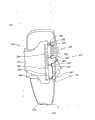
图1所示为本发明的实施例矫形夹具20的一个实施例。所述矫形夹具20通常包括:通过使用系带装置固定在使用者的腿部的膝部夹具,所述系带装置包括两个系带系统22a和22b,从而所述膝部夹具能够完全围绕并保护使用者的膝部。所述矫形夹具尤其适用于减轻关节压力和/或支持膝部关节。 Figure 1 shows an embodiment of an orthopedic jig 20 according to an embodiment of the present invention. The orthopedic brace 20 generally includes a knee brace secured to the user's leg by using a strap arrangement comprising two strap systems 22a and 22b so that the knee brace can completely enclose and Protect the user's knees. The orthopedic brace is particularly suitable for relieving joint stress and/or supporting the knee joint. the
通常来说,膝部夹具能够在前面的十字形韧带丢失或毁坏时,抵制胫骨的前移。由于各种原因会发生这种胫骨前移,而且在人们参加如下身体动作时常常发生,如快速左转或右转、快速停止、快速跳起、后向跑或其它类型的运动。当前面的十字形韧带丢失或毁坏时,如果人们只是简单地将他或她的腿从弯曲伸展到到完全伸直的状态,胫骨前移也会发生。尽管上述实施例只示出了用于膝部夹具的系带系统,应当明确的是,这里讨论的原则能够应用于任何一种矫形夹具,包括踝部夹具、腕部夹具、足部夹具、肘部夹具以及本领域技术人员熟知的许多其它类型的矫形夹具。正如本领域技术人员所知,可以对本发明的实施例的夹具做轻微改动,而使其能够实现上述各种功能。同样地,显而易见地,本发明所述的原则能够被应用于设计成穿戴于人或动物的身体的上各种装置或设备,包括:垒球、棒球、足球或曲棍球等运动所用的胫骨、腿部、臂部、肩部的防护装置或防护垫等。类似的装置还有包括马匹所用的胫骨防护装置在内的动物用防护装置。 In general, a knee splint resists anterior translation of the tibia when the anterior cruciate ligament is lost or destroyed. This tibial anterior shift can occur for a variety of reasons, and often occurs when a person engages in body movements such as quick left or right turns, quick stops, quick jumps, running backwards, or other types of motion. Anterior tibial shift can also occur when the anterior cruciate ligament is lost or destroyed if a person simply extends his or her leg from a bent to a fully extended position. Although the above embodiments only show a lacing system for a knee brace, it should be clear that the principles discussed here can be applied to any type of orthopedic brace, including ankle braces, wrist braces, foot braces, elbow braces, and ankle braces. Orthopedic braces, as well as many other types of orthopedic braces known to those skilled in the art. As known by those skilled in the art, slight modifications can be made to the clamp in the embodiment of the present invention, so that it can realize the above-mentioned various functions. Likewise, it should be apparent that the principles described in this invention can be applied to a variety of devices or equipment designed to be worn on the body of a human or animal, including: , arm, shoulder protective device or protective pad, etc. Similar devices are guards for animals including shin guards for horses. the
在本发明的实施例中,所述锁紧系统的系带装置包括两个分离的系带系统22a和22b。在本发明的实施例中,所述系带系统22a、22b起同样的作用。当然,如本领域技术人员所知,所述系带系统22a、22b在不同的实施例中可以是不同的,也可以各自包括与这里所述的不同的实现方式。在本发明的实施例中,各个系带系统22包括一条系带或一条绳索23,所述系带或绳索缠绕在所述矫形夹具的某个部分上,并将相对的一头安装到锁紧装置25上,这将会在后面作进一步的描述。除非特别说明这里所述的系带或绳索代表相同的意思。所述系带23优选为一种摩擦力较小的系带,能够相对较为容易地从所述矫形夹具20中穿过,从而能够在系带区的整个长度上方便的自动均衡所述矫形夹具20的张力。 In an embodiment of the invention, the lacing means of the locking system comprises two separate lacing systems 22a and 22b. In an embodiment of the invention, the strap systems 22a, 22b serve the same purpose. Of course, as known to those skilled in the art, the strap systems 22a, 22b may be different in different embodiments, and each may include different implementations than those described here. In an embodiment of the invention, each strap system 22 includes a strap or cord 23 that is wrapped around some portion of the orthopedic brace and mounts the opposite end to the locking device. 25, which will be further described later. Unless otherwise stated, straps or ropes herein mean the same. The tether 23 is preferably a tether with low friction, which can pass through the orthopedic jig 20 relatively easily, so that the orthopedic jig can be easily and automatically balanced over the entire length of the lacing area. 20 tension. the
图1所示的矫形夹具20用于使用者的腿部。上护腕10设计用于使用者的大腿部,因而是沿着大腿部线条成型,通常符合使用者的肌肉组织。下护腕12的结构与上护腕10类似,用于匹配并环绕使用者的小腿部。在本发明的实施例中,上护腕10和下护腕12由相对较轻的、透气的材料制成。在本发明的实施例中,正如本领域技术人员熟知的,上护腕10和下护腕12可以采用布料、织物或类泡沫材料等制造。 The orthopedic brace 20 shown in FIG. 1 is applied to a user's leg. The upper cuff 10 is designed to fit on the user's thigh and is thus shaped along the line of the thigh, generally conforming to the user's musculature. The structure of the lower wrist 12 is similar to that of the upper wrist 10, and is adapted to match and wrap around the lower leg of the user. In an embodiment of the present invention, upper wristband 10 and lower wristband 12 are made of a relatively lightweight, breathable material. In the embodiment of the present invention, as is well known to those skilled in the art, the upper wrist guard 10 and the lower wrist guard 12 can be made of cloth, fabric or foam-like materials. the
所述上护腕10和下护腕12通过至少一个支柱配件14结合在一起,所述支 柱配件14包括通过铰接部件19连接在一起的上支柱16和下支柱18。所述铰接部件19的固定方式优选为允许所述上支柱16能够相对下支柱18旋转,以及佩戴者的膝部的相应弯曲。上支柱16能够通过任意数目的扣紧装置设置到上护腕10上,例如,螺钉、黏胶、螺纹或这些装置的任意结合。所述下支柱18可以用同样的方式安装到所述下护腕12上。 The upper wrist guard 10 and the lower wrist guard 12 are joined together by at least one strut fitting 14, and the strut fitting 14 includes an upper strut 16 and a lower strut 18 connected together by a hinge member 19. The hinge member 19 is preferably fixed in such a way as to allow rotation of the upper strut 16 relative to the lower strut 18, and corresponding bending of the wearer's knee. The upper post 16 can be provided to the upper brace 10 by any number of fastening means, such as screws, glue, threads, or any combination of these means. The lower strut 18 can be mounted to the lower wrist 12 in the same manner. the
如图所示,上护腕10和下护腕12一般可以由单片材料环绕自身形成,同时形成两个相互接近的、实际上是交叠在一起的两个端部32和34。在本发明的实施例中,上护腕10和下护腕12在所述铰接部件所在的位置通过其它材料连接在一起,在佩戴者的膝部的前部和/或后部通常留有一个开口。一般来说,将所述系带23拉紧来使所述端部32、34互相拖曳交叠,从而将所述矫形夹具20在佩戴者的肢体上张紧,以下将会做进一步的描述。尽管图中所述端部32、34相互交叠,可以理解的,当所述矫形夹具20被拉紧时这两个端部也可以设计为一定距离的分离。因此,这里所提及的矫形夹具的相对端部仅仅是指安装到所述系带系统22a和22b相对的两边。对于交叠或不交叠的夹具或其它装置,上述相对端部都不是特定的。总的来说,可以通过将夹具或装置相对的两边相互对拉、或更常用地,拉动系带系统的侧面,就可以将所述夹具拉紧。 As shown, upper wristband 10 and lower wristband 12 may generally be formed from a single piece of material that wraps around itself while forming two ends 32 and 34 that are adjacent to each other and actually overlap. In an embodiment of the present invention, the upper wrist guard 10 and the lower wrist guard 12 are connected together by other materials at the position where the hinged part is located, and there is usually a Open your mouth. Generally, the strap 23 is tensioned so that the ends 32, 34 drag and overlap each other, thereby tensioning the orthopedic brace 20 on the wearer's limb, as will be further described below. Although the ends 32 , 34 overlap each other in the figures, it is understood that the two ends can be designed to be separated by a certain distance when the orthopedic jig 20 is tightened. Thus, references herein to the opposite ends of the orthopedic brace simply refer to the opposite sides attached to the strap systems 22a and 22b. Neither of the aforementioned opposing ends is specific to overlapping or non-overlapping clamps or other devices. In general, the clamp can be tightened by pulling opposite sides of the clamp or device against each other, or more commonly, the sides of the lacing system. the
优选地,矫形夹具的上护腕10和下护腕12的外表面28的摩擦很小,从而在将系带23拉紧时端部32、34和系带23在外表面28上易于滑动。所述摩擦小的外表面28可以与所述夹具20一体成型,也可以通过黏胶、热焊、缝纫等方式安装到所述夹具20上。在本发明的一个实施例中,所述夹具20的外表面28与所述系带23连接,并通过一层柔软的尼龙或四氟乙烯胶着到所述夹具20的外表面上。 Preferably, the outer surfaces 28 of the upper 10 and lower 12 braces of the orthopedic brace have low friction so that the ends 32, 34 and the lace 23 slide easily on the outer surface 28 when the lace 23 is tightened. The outer surface 28 with low friction can be integrally formed with the clamp 20 , and can also be installed on the clamp 20 by means of glue, heat welding, sewing or the like. In one embodiment of the present invention, the outer surface 28 of the clamp 20 is connected to the strap 23 and glued to the outer surface of the clamp 20 by a layer of soft nylon or tetrafluoroethylene. the
如图1所示,在本发明的实施例的各系带系统22中,系带23位于两个平行排列的边界保持部件40之间,并以交叉的方式环绕在所述夹具20的外表面。所述边界保持部件40可以包括安装在所述夹具20上的条状物,所述边界保持部件限定了引导部件50的位置。系带23在张紧或松开时穿过引导部件50,以下将进一步进行详细描述。在所描述的实施例中,在所述系带系统22的其中一边有一个边界保持部件40,而在另一边则有两个边界保持部件40。当然,在其 它的实施例中,边界保持部件40的数目是可变的,四个、五个或六个边界保持部件40都是可行的。在本发明的实施例中,所述边界保持部件的长度是可变的,从而能够更好地适应各种不同病人的腿部。如图2~4所示,对这样的实施例进行了更加详尽地描述。 As shown in FIG. 1 , in each lacing system 22 of the embodiment of the present invention, the lacing 23 is located between two parallel-arranged boundary retaining components 40 , and wraps around the outer surface of the clamp 20 in a crossing manner. . The boundary keeping member 40 may include a strip mounted on the clamp 20 , the boundary keeping member defining the position of the guiding member 50 . The tether 23 passes through the guide member 50 when tensioned or loosened, as will be described in further detail below. In the depicted embodiment, there is one boundary retaining member 40 on one side of the strap system 22 and two boundary retaining members 40 on the other side. Of course, in other embodiments, the number of boundary keeping components 40 is variable, and four, five or six boundary keeping components 40 are all feasible. In an embodiment of the present invention, the length of the boundary maintaining member is variable, so as to better adapt to the legs of various patients. Such an embodiment is described in more detail, as shown in Figures 2-4. the
所述引导部件50可以通过本领域技术人员所熟知的各种方式安装到所述矫形夹具20上。例如,所述边界保持部件40并不是必要的,可以将所述引导部件50直接缝合到所述矫形夹具20。将引导部件50直接缝合到所述矫形夹具20上将有利于实现对引导部件50整个长度上的力量分布的最佳控制。例如,当系带23上施加了一个相对较大的张力,引导部件50可能会弯曲甚至有可能扭曲。在张力下引导部件50的弯曲会增加所述引导部件50和所述系带23之间的摩擦,并且引导部件50的严重弯曲或扭曲会严重影响到系带系统22的预期功能。因此,将引导部件50安装到矫形夹具20上的安装装置优选能够为引导部件50提供足够的支持来抵抗弯曲和/或扭曲。在上述方案的基础上,可选地,引导部件自身也设计为能够抵抗弯曲和/或扭曲。在任何弯曲部位的内径上都尤其需要足够的支持,特别是靠近引导部件50的端部的位置。除了要能够抵抗弯曲的安装装置外,引导部件50自身也应以能够抵抗弯曲的方式来成型。 The guide member 50 can be mounted on the orthopedic jig 20 in various ways known to those skilled in the art. For example, the boundary retaining member 40 is not necessary and the guide member 50 may be sewn directly to the orthopedic jig 20 . Sewing the guide member 50 directly to the orthopedic brace 20 will facilitate optimal control of force distribution over the entire length of the guide member 50 . For example, when a relatively high tension is applied to the tether 23, the guide member 50 may bend or even twist. Bending of the guide member 50 under tension increases friction between the guide member 50 and the tether 23 , and severe bending or twisting of the guide member 50 can seriously affect the intended function of the lacing system 22 . Accordingly, the mounting means by which the guide member 50 is mounted to the orthopedic brace 20 is preferably capable of providing sufficient support for the guide member 50 to resist bending and/or twisting. On the basis of the above solution, optionally, the guide member itself is also designed to be able to resist bending and/or twisting. Adequate support is especially needed on the inner diameter of any bend, especially near the end of the guide member 50 . In addition to the mounting means being able to resist bending, the guide part 50 itself should also be shaped in such a way that it is resistant to bending. the
在本发明的实施例中,每一个引导部件50包括了一对开口49,所述开口49能够与穿过内腔54的相对端相通。所述开口49用作所述系带23的入口/出口。开口49至少与所述内腔54的横截面一样大。 In an embodiment of the invention, each guide member 50 includes a pair of openings 49 capable of communicating with opposite ends through the lumen 54 . The opening 49 serves as an inlet/outlet for the tether 23 . The opening 49 is at least as large as the cross section of the interior space 54 . the
当系带系统22被拉紧时,相对的引导部件50之间的距离也会变小。对于某些产品,佩戴者希望将夹具的某些部位系的比其他部位更紧些。从另一个角度说,即佩戴者会希望将所述夹具局部系紧,即不同的位置有不同的张力。在本发明的实施例中,在拉紧的过程中通过限定特定的引导部件50在向对方移动时要大于一个预先选定的最小距离,就能够很方便地实现这一点。为了实现这个目的,需要为系带系统22提供具有各种长度的取间隔装置、动态取间隔装置或障碍物(未示出)选择。一般来说,这些限制物为夹具产生了局部张力、从而根据佩戴者的需要在用户定制的位置加强了张力。还可以通过其它方式产生局部张力。例如,可以使用附加的锁紧装置25。在本发明的实施例中,为每一 对相对设置的系带引导部件都提供了一个锁紧装置25。如图1所示的实施例中,可以提供三或四个锁紧装置25从而允许为所述夹具20提供附加的用户定制的张力。在本发明的实施例中,可以使用专门的系带的引导部件来产生局部张力。在本发明的实施例中,在所述夹具的同样位置上提供一条狭槽和一个导向装置,从而系带能够在那个位置进行两次缠绕以增加该位置的张力。在本发明的实施例中,将一个以上锁紧装置和专门的系带组件联合在一起也能够提供局部压力。产生局部张力的实施例在公开号为2006-0156517的美国专利中做了更详细的说明,本申请将其全部内容通过引用结合在本申请中。 When the lacing system 22 is tightened, the distance between the opposing guide members 50 also decreases. With some products, the wearer may wish to fasten some parts of the clamp tighter than others. On the other hand, the wearer may wish to tighten the clamp locally, ie different tensions at different locations. In embodiments of the present invention, this is conveniently accomplished by limiting the movement of certain guide members 50 towards each other by greater than a preselected minimum distance during tensioning. To accomplish this, it is desirable to provide the strap system 22 with a choice of spacers, dynamic spacers or obstacles (not shown) of various lengths. Generally, these restraints create localized tension on the clamp, thereby reinforcing the tension at user-customized locations according to the wearer's needs. Local tension can also be generated by other means. For example, an additional locking device 25 can be used. In an embodiment of the invention, a locking device 25 is provided for each pair of oppositely disposed lacing guide members. In the embodiment shown in FIG. 1 , three or four locking devices 25 may be provided to allow additional user-defined tensions for the clamp 20 . In embodiments of the present invention, dedicated lacing guide components may be used to generate localized tension. In an embodiment of the invention, a slot and a guide are provided at the same location of the clamp so that the lace can be wrapped twice at that location to increase the tension at that location. In embodiments of the present invention, localized compression can also be provided by combining more than one locking device with a dedicated strap assembly. Examples of generating localized tension are described in more detail in US Patent Publication No. 2006-0156517, the entire contents of which are incorporated herein by reference. the
在所描述的实施例中,各引导部件50为“U”形,并且开口朝向系带系统22的中心线。优选地,各引导部件50在开口49之间有一个纵向距离。当系带23收紧时,所述纵向距离的长度可以变化,从而调节系带23施加在矫形夹具20上的锁紧压力的分布。而且,对于一个特定夹具上的所有引导部件50而言,所述纵向距离的长度不需要完全相同的。进一步地,例如,从所述铰接部件19起沿着所述夹具20的引导部件,所述纵向距离可以被缩短。从而将所述系带23施加到腿上相应部位的锁紧压力增大。一般来说,所述纵向距离的长度在1/2英寸到3英寸的范围之间,并且在一些实施例中,也可以在约1/4英寸到约4英寸之间。在所述开口49之间的纵向距离越小,在所述系带区域的特定部件上的锁紧压力将越大。 In the depicted embodiment, each guide member 50 is "U" shaped and opens towards the centerline of the lacing system 22 . Preferably, each guide member 50 has a longitudinal distance between the openings 49 . When the tether 23 is tightened, the length of the longitudinal distance can be changed, so as to adjust the distribution of the locking pressure exerted by the tether 23 on the orthopedic clamp 20 . Also, the length of the longitudinal distance need not be exactly the same for all guide members 50 on a particular jig. Further, the longitudinal distance may be shortened, for example, along a guide part of the clamp 20 from the hinge part 19 . Thereby, the locking pressure applied to the corresponding part of the leg by the tether 23 is increased. Generally, the length of the longitudinal distance ranges from 1/2 inch to 3 inches, and in some embodiments, may also range from about 1/4 inch to about 4 inches. The smaller the longitudinal distance between the openings 49, the greater will be the locking pressure on a particular part of the lacing area. the
所述引导部件50优选采用小摩擦的材料制造,例如光滑的聚合体或金属,从而便于所述系带23的滑动。可选地,所述引导部件50可由任何易于得到的、很坚硬的材料制成,并且至少可以在滑道上涂上一层光滑的覆盖层以减小摩擦。优选地,所述引导部件50需足够坚硬,从而在系带23被张紧时,所述引导部件50和/或在任何一个所述引导部件50中的系带23都不易弯曲和扭曲。 The guide member 50 is preferably made of low-friction material, such as smooth polymer or metal, so as to facilitate the sliding of the tether 23 . Optionally, the guide member 50 can be made of any readily available, very hard material, and at least one layer of smooth coating can be applied on the slideway to reduce friction. Preferably, the guide members 50 are stiff enough so that the guide members 50 and/or the tether 23 in any one of the guide members 50 are not prone to bending and twisting when the tether 23 is tensioned. the
可选地,所述引导部件可以包括一个有开口的通道,所述通道具有可为半圆形或“U”的横截面(例如,图8A所示的与另一个实施例结合在一起的示意图)。所述引导通道的开口最好背对着所述系带系统的中心线,从而使得被收紧的系带能够固定在所述通道中。在一些实施例中,可以提供一个或多个固定带、缝合物或封口物将通道的开口边“关闭”,从而避免所述系带上的张力释放时, 所述系带从所述通道中逃脱。在其它的实施例中,所述通道的开口边保持打开,便于所述系带从所述引导部件中移开,从而允许增大所述装置的开口,如果将所述系带固定到所述通道时则无法增大所述装置的开口。装置的开口大一些比较好,例如,在由于受伤而难以将义肢安进所述装置的情况下。可选地,在一些实施例中,所述引导部件是关闭的,但为可移动地安装到所述夹具上,从而通过将所述引导部件和系带从所述夹具上移开,就能够得到一个更大的开口。在一些实施例中,还可以采用这些引导部件的不同组合。 Optionally, the guide member may comprise an open channel having a cross-section which may be semicircular or "U" (for example, the schematic diagram shown in Figure 8A in conjunction with another embodiment ). The opening of the guide channel is preferably facing away from the centerline of the lacing system so that a tightened lacing can be secured in the channel. In some embodiments, one or more straps, sutures or closures may be provided to "close" the open sides of the channel, thereby preventing the ligament from being released from the channel when the tension on the lace is released. escape. In other embodiments, the open side of the channel remains open to facilitate removal of the tether from the guide member, thereby allowing the opening of the device to be enlarged if the tether is secured to the When channeling, the opening of the device cannot be enlarged. A larger opening to the device is better, for example, in cases where it is difficult to fit a prosthetic into the device due to an injury. Optionally, in some embodiments, the guide member is closed but is removably mounted to the clamp so that by removing the guide member and strap from the clamp, the Get a bigger opening. In some embodiments, different combinations of these guide components may also be employed. the
几个引导部件的导向通道可以一体成型,可以成型为一个能够黏附或缝合到所述夹具上的常规的带状支持物。如图5和图6所示,描述了这样的实施例。引导部件的实施例在公开号为2006-0156517和2007-0169378的美国专利申请文件中有更为详细的描述,本申请通过引用将其结合到本申请中。 The guide channels of several guide members can be formed integrally, and can be formed as a conventional tape support that can be glued or sewn to the jig. As shown in Figures 5 and 6, such an embodiment is described. Examples of guide members are described in more detail in US Patent Application Publication Nos. 2006-0156517 and 2007-0169378, which are incorporated herein by reference. the
系带23可以通过各种聚合物、金属材料或它们的结合物成型,从而能够为本发明实现足够的轴向力和弯曲性能。例如,能够通过编织、交织、扭曲或任何其它的方式变形的任何固体实心金属线、固体实心聚合体、或多纤维丝金属线或聚合体都可以被使用。可以在固体或多纤维的实心金属上覆盖一层聚合物,例如聚四氟乙烯(PTFE)或其它现有技术的其它材料形成的覆盖物,从而减小摩擦。在一个实施例中,系带23包括一条搓成的缆索,例如可以是由7×7的人造不锈钢绳搓成的缆索。为了在所述系带23以及系带23需要在其表面移动的引导部件50之间减小摩擦,系带23的表面最好覆盖一层光滑材料,例如尼龙或特氟纶(Teflon,也称聚四氟乙烯)。在一个优选的实施例中,系带23的直径可以在0.024英寸到0.060之间变化,并且最好为0.032英寸。系带23必须足够强韧从而能够承载至少40磅最好是至少90磅的张力。在特定的实施例中,系带需要在100磅至高达200磅或更大的张力之间进行测试。 The tether 23 can be formed from various polymers, metallic materials or combinations thereof so as to be able to achieve sufficient axial force and bending performance for the present invention. For example, any solid solid wire, solid solid polymer, or multifilament wire or polymer capable of being deformed by braiding, interweaving, twisting, or any other means may be used. The solid or fibrous solid metal can be covered with a polymer such as polytetrafluoroethylene (PTFE) or other materials known in the art to reduce friction. In one embodiment, the tether 23 includes a twisted cable, for example, a twisted cable made of 7×7 artificial stainless steel ropes. In order to reduce friction between the tether 23 and the guide member 50 on which the tether 23 needs to move, the surface of the tether 23 is preferably covered with a smooth material such as nylon or Teflon (also known as Teflon). polytetrafluoroethylene). In a preferred embodiment, the diameter of the tether 23 can vary from 0.024 inches to 0.060 inches, and is most preferably 0.032 inches. Tether 23 must be strong enough to carry a tension of at least 40 lbs and preferably at least 90 lbs. In certain embodiments, the laces need to be tested between 100 pounds of tension up to 200 pounds or more. the
如图1所示,锁紧装置25被安装到矫形夹具20上。尽管图中所示的所述锁紧装置25被安装到夹具20的侧面上,但应当明确,锁紧装置25可以被安装到夹具20上的任何位置。锁紧装置25在定位时需要考虑到不同的方面,例如夹具的整体设计和夹具的使用目的等。锁紧装置25的形状或整体体积也可以根据传动装置的排列设计、使用目的以及在夹具20上的位置在很大范围内变化。 锁紧装置25最好具有相对小的轮廓。通过使锁紧装置25凹进夹具20的外表面28,可以使所述锁紧装置25的安装轮廓进一步减小。此外,与前面所述的引导部件相似,锁紧装置25设计为可移动地固定在所述夹具20上,便于取下所述夹具20。例如,锁紧装置25上的容置部件60可以抽取式地塞入夹具上的凹处。 As shown in FIG. 1 , a locking device 25 is mounted to the orthopedic brace 20 . Although the locking device 25 is shown mounted to the side of the clamp 20 , it should be understood that the locking device 25 may be mounted anywhere on the clamp 20 . When positioning the locking device 25 , different aspects need to be considered, such as the overall design of the clamp and the purpose of use of the clamp. The shape or overall volume of the locking device 25 can also vary in a wide range according to the arrangement design of the transmission device, the purpose of use and the position on the clamp 20 . The locking device 25 preferably has a relatively small profile. By recessing the locking device 25 into the outer surface 28 of the clamp 20, the mounting profile of the locking device 25 can be further reduced. In addition, similar to the above-mentioned guide components, the locking device 25 is designed to be movably fixed on the clamp 20 to facilitate the removal of the clamp 20 . For example, the accommodating part 60 on the locking device 25 can be plugged into the recess on the clamp in a detachable manner. the
通常来说,锁紧装置25包括一个控制器,例如控制杆、曲柄或球形捏手,能够控制绕起系带23。而且,所述锁紧装置25最好包括释放部件,例如按钮或控制杆来释放所述锁紧装置25,从而使得系带23可以自由地释放。在一些实施例中,所述锁紧装置可以通过将所述控制器向外拉来进行释放。在一些实施例中,还提供了一个附加的锁紧部件,例如按钮或控制杆,所述附加的锁紧部件可以启动向外拖动所述控制器,从而释放所述系统。 Typically, the locking device 25 includes a controller, such as a lever, crank or knob, capable of controlling the winding of the tether 23 . Moreover, the locking device 25 preferably includes a release member, such as a button or a lever to release the locking device 25, so that the tether 23 can be released freely. In some embodiments, the locking device can be released by pulling the control outward. In some embodiments, there is also provided an additional locking member, such as a button or lever, which can be activated to pull the control outwardly, thereby releasing the system. the
上述实施例中所描述的所述锁紧装置25一般包括一个容置部件60和一个安装在此的可旋转的球形捏手62。所述球形捏手62可以通过旋转将所述系带23的末端绕进所述容置部件60,从而为系带23提供决定性的张力以避免松弛并提供所需的力度。当系带23上的松弛度被减小,系带23拉动引导部件50从而使端部32、34相对移动,使得环绕在佩戴者腿部的所述夹具20的上护腕10和下护腕12收紧。通过使用安装在所述捏手62上的工具或小电动机,所述球形捏手62也能够旋转。适用于这个目的的各种锁紧装置的实施例,在申请号为2006-0156517和2007-0169378的美国专利申请文件中进行了更详细的描述,本申请通过引用将其结合在本申请中。 The locking device 25 described in the above embodiments generally includes a receiving part 60 and a rotatable knob 62 mounted therein. The knob 62 can rotate the end of the tether 23 into the accommodating part 60 , so as to provide a decisive tension for the tether 23 to avoid slack and provide the required force. When the slack on the strap 23 is reduced, the strap 23 pulls on the guide member 50 so that the ends 32, 34 move relative to each other so that the upper and lower wristbands 10, 34 of the clamp 20 encircle the wearer's leg. 12 Tighten. The knob 62 can also be rotated by using a tool or a small electric motor mounted on the knob 62 . Examples of various locking devices suitable for this purpose are described in more detail in US Patent Application Nos. 2006-0156517 and 2007-0169378, which are incorporated herein by reference. the
系带23和引导部件50之间的低摩擦关系大大的方便了所述系带系统22的拉紧和松开。尤其是,由于系带23和引导部件50制作中可能覆盖了一层摩擦很小的材料,系带23不需用力就能很容易穿过所述引导部件。这样系带23能够在其整个长度上自动分布张力,从而能够沿着系带区域的整个长度上均匀的分布锁紧张力。当通过启动所述释放控制杆(图中未示出)或向外拉动所述球形捏手62来释放所述系带23中的张力时,系带23能够从所述缆索部件50中轻易地穿过,从而能够在所述系带的整体上释放张力并平均分布松弛力度。 The low friction relationship between the strap 23 and the guide member 50 greatly facilitates tightening and loosening of the strap system 22 . In particular, since the tether 23 and the guide member 50 may be manufactured with a layer of material with little friction, the tether 23 can easily pass through the guide member without using force. This way the lace 23 can automatically distribute the tension over its entire length so that the locking tension can be evenly distributed along the entire length of the lace area. When the tension in the tether 23 is released by activating the release lever (not shown) or pulling the knob 62 outward, the tether 23 can be easily released from the cable member 50. through, thereby releasing the tension and evenly distributing the slack throughout the lace. the
系带23和缆索导向部件50之间的低摩擦关系也大大方便了所述夹具20上的不同松紧度的部件之间的动态关系。例如,当配戴者的腿在运动时弯曲,大 腿部充血并且膨胀,系带系统22a的上部件能够相对于所述系带系统22a的下部膨胀。从而,低摩擦使得所述矫形夹具20能够对其中变化的体积进行动态的响应。在另一个实施例中,如果下护腕12和上护腕10是通过一体的系带系统安装到佩戴者身上时,沿着整个夹具20上的张力可以被所述系带系统22平均地分配。 The low friction relationship between the strap 23 and the cable guide member 50 also greatly facilitates the dynamic relationship between the different tension components on the clamp 20 . For example, when the wearer's legs bend during exercise, the thighs engorged and swell, and the upper portion of the lacing system 22a can expand relative to the lower portion of the lacing system 22a. Thus, low friction enables the orthopedic splint 20 to respond dynamically to changing volumes therein. In another embodiment, if the lower wristband 12 and the upper wristband 10 are mounted on the wearer through an integrated lacing system, the tension along the entire clamp 20 can be evenly distributed by the lacing system 22 . the
总的来说,设计系带系统时,需要减小在使用中所述系统的组件挂住衣服或其他物体的可能性。例如,可以将系统设计成在锁紧时保持很小的轮廓。如上面所提到的,一种可能是将锁紧装置置入夹具中凹进的部分。另一个选择是采用一个覆盖物,所述覆盖物可以独立使用或者与凹进设置的锁紧装置结合使用。在一些实施例中,所述覆盖物可以包括织物或其它柔软的材料,所述覆盖物的至少一边沿被固定的安装到夹具上或所述锁紧装置的容置部件上,所述覆盖物的一个或多个其他边沿通过按扣、按钮或维可牢尼龙搭扣(Velcro)等采用可移动的方式进行安装。在一些实施例中,所述覆盖物包括一个由塑料这样的材料制成的硬质部件,并通过铰接部件安装到夹具上,铰接部件使得所述覆盖物能够旋出露出所述锁紧装置、以及旋回覆盖所述锁紧装置。在一些实施例中,硬质和软质材料可以结合起来。在一些实施例中,一个覆盖物能够覆盖所述系带系统的某些或者全部部件,包括系带、系带的引导部件和锁紧装置。 In general, when designing a lacing system, there is a need to reduce the likelihood that components of the system will catch clothing or other objects while in use. For example, the system can be designed to maintain a low profile when locked. As mentioned above, one possibility is to place the locking device in a recessed part of the clamp. Another option is to use a covering that can be used by itself or in combination with a recessed locking device. In some embodiments, the covering may include fabric or other soft materials, at least one edge of the covering is fixedly mounted on the clamp or the receiving part of the locking device, the covering One or more other edges of the can be removably mounted by snap buttons, buttons, or Velcro. In some embodiments, the cover comprises a rigid part made of a material such as plastic and is mounted to the clamp by a hinged part which allows the cover to be unscrewed to expose the locking means, And swivel cover said locking device. In some embodiments, hard and soft materials may be combined. In some embodiments, a cover can cover some or all of the components of the lacing system, including the lacing, lacing guide components, and locking devices. the
在一些实施例中,可以采用一个从所述容置部件向外延伸的防护物,用于覆盖所述锁紧装置的控制器的至少一个部分。有关用于保护部分或全部控制器的防护物的实施例在公开号为2006-0156517的美国专利申请中进行了详细的阐述,该申请的内容通过引用结合在本申请中。 In some embodiments, a shield extending outwardly from the receiving part may be used to cover at least a portion of the control of the locking device. Examples of shields for protecting some or all of the controllers are described in detail in US Patent Application Publication No. 2006-0156517, the contents of which are incorporated herein by reference. the
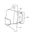
如图2、图3所示,提供了另一个夹具120,包括一个锁紧系统122,所述锁紧系统122包括粗调组件,能够将夹具120进一步打开来将夹具120佩戴到佩戴者的腿部101,最终还能够使用锁紧装置125来进行锁紧。上护腕110根据佩戴者的大腿成型,与大腿一致弯曲成型,一般与佩戴者的肌肉组织相符。下护腕112与上护腕110的结构类似,根据佩戴者的小腿成型,与小腿一致弯曲成型。在所描述的实施例中,上护腕和下护腕包括在膝关节附近将它们连接到一起的附加材料,因而在一些实施例中它们可以如图1所示的分开成型。 As shown in Figures 2 and 3, another
如前面的实施例所述,上护腕110和下护腕还可以通过至少一个压杆114进行结合,所述压杆包括通过铰接部件119结合在一起的上压杆116和下压杆118。所述铰接部件119优选相对于下压杆118能够绕着上压杆116旋转,并能够随着佩戴者的膝部一起弯曲。 As described in the previous embodiments, the
在一些实施例中,护腕110和112可以由整片材料环绕自身而成,并形成两个相互接近的、也可以是交叠在一起的两个端部。系带123可以张紧从而将所述两个端部互相交叠,因而能够将缚于佩戴者的肢体上的夹具120拉紧。可选地,所述端部还包括一个初始安装装置,例如维可牢尼龙搭扣(Velcro)或者类似装置(图中未示出),所述初始安装装置能够在拉紧整个系统之前为所述端部提供一个初始的连接。在这种情况下,系带23拉紧使引导部件150相向靠近,除了将所述端部拉近,还将绕在肢体上的护腕压紧。 In some embodiments,
如图2所示,在一些实施例中,每个系带或锁紧系统122包括系带123,系带123沿着所述夹具120的侧面,即两个平行排列的引导部件150之间的部位,以交叉的方式穿行。在一些实施例中,锁紧装置125边上的所述引导部件150可以与所述锁紧装置125中的容置部件160一体成型。与所述锁紧装置125这一侧设置的引导部件150相对设置的引导部件150可以滑动式地安装到所述夹具120上的完全平行的轨道170上,具体原因将在下面描述。 As shown in FIG. 2 , in some embodiments, each strap or locking system 122 includes a
在一些实施例中,最好采用不同的长度保持部件140来更好地适应不同配戴者的腿部。在一些实施例中,保持部件140设置为可松开式地与同所述锁紧装置125相对设置的引导部件150相连接。可以通过快速释放部件142,例如Fastex带扣(图中所示)、维可牢尼龙搭扣(Velcro)或其它本领域所用的类似的工具,实现所述保持部件与所述引导部件150之间的连接。如图3所示,各个带扣142包括母组件142a和公组件142b。在一些实施例中,所述母组件142a可以安装到引导部件150上,公组件142b安装到保持部件上,可以根据需要来调换它们之间的排布。所述保持部件140的相对的一端可以安装到夹具上,当带扣142连接起来时,这样系带系统122a和122b上产生的张力就能够在所述保持部件140上产生张力,从而将围绕配戴者肢体的护腕压紧。在一些实施例中,保持部件140安装到夹具120上与所述锁紧系统122相同的一侧,而在有 些实施例中,保持部件140与所述锁紧系统122相对设置。 In some embodiments, it may be desirable to use different
锁紧系统122可以包括与所述快速释放部件142相结合来提供对所述夹具120上的锁紧压力的粗略调整的附加的粗调部件,这样在使用所述锁紧装置125之前即可实现对夹具120上的锁紧压力的调整。例如,锁紧系统122可以包括框形环(ladder loops)144,使得保持部件140能够根据需要被拉长或缩短。图中示出了两个保持部件140,但本发明的实施例中保持部件140的个数可以是各种的。在一些实施例中,三个、四个、五个、六个或更多的保持部件140都是可以的。 The locking system 122 may include an additional coarse adjustment component in combination with the
如上所述,各个引导部件150包括一对开口149,每一个所述开口149能够穿过内腔154与另一个所述开口149相通。所述开口149用作所述系带123的入口/出口。 As mentioned above, each
在一些实施例中,所述系带123在拉紧时,为了使得所述引导部件150和系带123在外表面128上易于滑动,所述夹具150的上护腕110和下护腕112的外表面128的摩擦应当相对较小。在一些实施例中,可以通过将一层柔软的尼龙或聚四氟乙烯黏胶或缝合到外表面128上来形成外表面128。 In some embodiments, when the
在图2所示的结构中,系带系统122a和122b的交叉方式会在与所述锁紧装置125相对的引导部件150上产生不平衡的张力。所述锁紧装置125产生的力包括两个部分,其中一部分力将所述引导部件朝与夹具的中心线完全平行的路径拉动,而另一部分力则将所述引导部件150拉离所述完全平行的路径,并且相向运动。在一些实施例中,与所述锁紧装置125相对设置的引导部件150安装到完全平行的轨道170上,从而使得所述引导部件150能够沿着所述完全平行的路径移动。当所述系带系统上施加了张力时,所述引导部件150沿着轨道170被拉动。最好保持引导部件150沿着完全平行的路径运动从而能够提高锁紧系统122的效率。例如,如果引导部件150被相向拉动,它们可能会缠结或捆绑在一起,从而引起佩戴者的不舒适感并可能会使得夹具从佩戴者的腿部101上滑下。 In the configuration shown in FIG. 2 , the criss-crossing of the
图3为夹具120部分打开状态下的一个实施例示意图。快速释放带扣142与安装到夹具上的引导部件150分离,并且释放了所述保持部件140的一端。 为了取下夹具120,使用者可以打开上护腕110和下护腕112,将夹具从使用者的腿部101上滑下。在松开带扣142之前,使用者可以通过释放所述锁紧装置125来释放所述锁紧系统122上的张力,例如,将所述球形拉手162向外拖出。可选地,使用者可以在松开带扣142后将所述锁紧装置125释放,从而能够通过给所述系统提供附加的松弛度以便重新安装夹具120,而不需要重新调节所述保持部件140。 FIG. 3 is a schematic diagram of an embodiment in a partially opened state of the
参照图4,图中示出了一个与夹具120相似的另一实施例夹具220,不同之处在于,在系带区域,系带没有形成交叉的形状。除了将“1”改成“2”,各个部件的附图标记都用类似的数字来表示。 Referring to FIG. 4, there is shown another embodiment of a
在一些实施例中,锁紧装置225可以包括一个带有四个开口249的引导部件250。可选地,中间的两个开口249可以形成一个独立的引导部件250,外侧的两个开口249可以与所述锁紧装置225一体成型。在图中所述的实施例中,位于底部的三个开口249形成了一个独立的引导部件225,而位于最上面的开口与所述锁紧装置225一体成型。系带223从所述锁紧装置225的底部穿出,沿着所述引导部件250背侧的三个底部的开口249,并且从位于最底部的开口249穿出。本领域的普通技术人员很清楚这些实现方式。 In some embodiments, locking
通过引入位于所述锁紧装置225的边上的一对开口249,系带223可以以完全平行、不交叠的路径穿过所述夹具220的外表面228。从而,开口249以完全平行的方式进行配置。这种配置方式有利于或者从根本上减少了要将所述引导部件150拉出它们所在的完全平行的路径的力。这样,在一些实施例中,就可以去除上述实施例中所示的轨道。可选地,仍然可以使用轨道来确保引导部件250相对于夹具220的设置位置。 By introducing a pair of
总的来说,这里公开的装置设计成便于使用者能够取下所述锁紧系统的至少一个部件,从而便于将肢体或身体的其它部位放入或移出所述装置。所述锁紧装置与所述快速释放部件的结合允许快速、粗略地对所述装置施加在身体上的张力进行调节,进一步地,在安装完成后还允许进一步的细微调节。而且,一个以上的锁紧系统使得使用者能够独立地、可选择地调整所述装置的不同部分的压力从而获得最舒适然而对于身体来说有效的配置。 In general, the devices disclosed herein are designed to allow a user to remove at least one component of the locking system to facilitate insertion or removal of a limb or other body part from the device. The combination of the locking device and the quick release allows for quick, rough adjustments to the tension the device exerts on the body, and further, further finer adjustments after installation has been completed. Furthermore, more than one locking system enables the user to independently and selectively adjust the pressure on different parts of the device to obtain the most comfortable yet physically effective configuration. the
参照图5和图6,图中示出了一种用于踝部303的夹具320。图5中,夹具320安装到了踝部303。图6为图5所示的夹具打开的示意图。夹具320包括第一踝护腕310和第二踝护腕312,它们通过连接部件313进行连接,并且紧靠在佩戴者的踝部303的外侧。踝部护腕310和312的外部可以包括一个硬质、或者特别硬质的部件来维护踝部的稳定性,内部可以包括一个弹性泡沫或充气部件在踝部产生舒适感。夹具320的一些实施例还可以进一步包括一个锁紧系统322,所述锁紧系统包括一个锁紧装置325、引导部件350、系带或缆索323和一个可释放式的保持部件340。 Referring to Figures 5 and 6, a
在所述的实施例中,所述夹具具有一个锁紧系统322用于快速而有效地调节适应不同尺寸的踝部。在一些实施例中,与锁紧装置325相对设置的引导部件350可以与四个开口349一体成型。这四个开口349优选与位于锁紧装置325一侧的开口349平行设置,从而能够为系带323提供一条完全平行的系带路径。采用这种方式的好处与上述夹具220的好处相同,包括去除或明显减少会引起保持部件交叠和/或缠结的非平行的张力。在踝部夹具中,当夹具需要容纳不同尺寸的肢体时,在夹具中再添加轨道或其它的装置来控制引导部件所经过的路径是非常困难的;而这种方式更有利于提供一个稳定的夹具,它能够方便地打开从而将踝部装进去。这里公开的实施例能够打开足够大从而将受伤的踝部装进去,并且能够对压力提供粗调和细调。 In the illustrated embodiment, the clamp has a
在所述的实施例中,采用维可牢尼龙搭扣(Velcro)为所述夹具320提供一个快速释放部件342。在将踝部303放入夹具320后,踝部护腕310和312将佩戴者的踝部303压紧,保持部件340和快速释放部件342a和342b一起将踝部紧紧环绕,从而使得夹具320能够预先贴缚在踝部。锁紧装置325用于完成最后的锁紧。在所述实施例中,所述锁紧装置325的球形捏手362通过旋转将处于松弛状态的系带323绕进容置部件360。通过将球形捏手362从容置部件360中拉出或松开所述快速释放部件342,可以将系带323上的张力释放。 In the illustrated embodiment, the
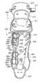
如图7~图9,公开了本发明的另一个实施例足部夹具420。足部夹具420的一些实施例包括第一侧面410和第二侧面420、足底座413、夹舌415和锁紧系统422。足部夹具420的第一侧面410和第二侧面420在外侧可以包括一个刚 性的、或特别硬质的部件用来为足部和踝部提供稳定支持,在内侧可以包括一个更有弹性的泡沫或充气部件为足部和踝部提供舒适感。类似地,夹舌415可以在外部包括一个刚性或特别硬质的部件来提供稳定和保护,在内部可以包括一个更软、弹性更好的部件来衬垫佩戴者的足部和踝部。图中所示夹具420为长统靴的形状用于支持佩戴者的足部和踝部。对所述夹具的其它改进也可以不包括踝部部分,这样它仅仅用来支持佩戴者的足部。其它的改进可以包括一个能够将佩戴者的部分或全部腿部包覆的更高的支持部件。 7-9, another embodiment of the foot clamp 420 of the present invention is disclosed. Some embodiments of foot clamp 420 include first side 410 and second side 420 , foot base 413 , jaw 415 , and locking system 422 . The first side 410 and the second side 420 of the foot clamp 420 may include a rigid, or particularly hard, member on the outside to provide stable support for the foot and ankle, and may include a more elastic member on the inside. Foam or air-filled parts provide comfort for the foot and ankle. Similarly, the tongue 415 may include a rigid or extra hard part on the outside to provide stability and protection, and a softer, more resilient part on the inside to cushion the wearer's foot and ankle. Clamp 420 is shown in the shape of a boot for supporting the wearer's foot and ankle. Other modifications to the brace could also exclude the ankle portion so that it only serves to support the wearer's foot. Other improvements could include a taller support member that wraps around part or all of the wearer's leg. the
更方便地,夹具420设计成有利于使用者的足部或踝部能够方便地进入或脱出。特别地,在一些实施中,这可以通过提供一个锁紧系统422来实现,所述锁紧系统包括允许所述侧面410和412之间的开口完全打开的快速释放部件以及能够完全从所述开口中移出的夹舌415。 More conveniently, the clamp 420 is designed to facilitate easy entry and exit of the user's foot or ankle. In particular, in some implementations, this may be accomplished by providing a locking system 422 that includes a quick release that allows the opening between the
在一些实施例中,系带或锁紧系统422包括系带423,系带423沿着所述夹具420上前向的部分、在两列平行排列的系带的引导部件450之间、交叉缠绕。如图7和细节示意的图8A所示,提供快速释放的一种方法是与所述锁紧装置425相对设置的具有开口端部的引导部件450联合使用。要打开夹具420,使用者可以通过将所述锁紧装置425上的球形捏手462拉出从而释放所述系带系统422上的张力。当系带423处于松弛状态时,佩戴者可以将系带423移出与所述锁紧装置相对设置的引导部件450,这样系带423就不会再跨越侧面410和412之间的区域。由于系带423已经不再起作用,夹舌415就能够很容易地从夹具420的开口中取出,配戴者则能够很容易地将他们的附属肢体放入所述夹具420中。 In some embodiments, the lacing or locking system 422 includes a lacing 423 that is cross-wrapped along a forward portion of the clamp 420 between two parallel rows of lacing
在一些实施例中,设置于夹具420的中部、且靠近佩戴者踝部的支点(pivotpoint)的引导部件450的开口449之间的距离比靠近夹具420的趾头处或夹具420的更高处的开口的距离更窄。距离更小可以增加支点所在区域的锁紧张力从而有利于将踝部和足部锁紧在夹具420中。在一些实施例中,在夹具420上、锁紧装置425所在的边上的包括一个或多个打开的、背侧开口的引导部件450更好,能够在所述锁紧系统422打开时增加使用者能够利用的松弛系带的长度。如图7所示为这种配置的例子。 In some embodiments, the distance between the
如图8B所示为上述背侧开口的引导部件的一个可选设计的示意图。如图8B所示的可移动的封闭式引导部件450可以替代图7或图8A所示的一个或多个背侧开口的引导部件。可移开的引导部件450可以以本领域技术人员所熟悉的一种或多种方式安装到夹具420上。例如,可以用吊钩将所述引导部件与所述夹具连接,并与所述夹具上的孔配套使用。可选地,吊钩可以成型于图中所示的靴形夹具上而与其配套的孔可以成型在引导部件上。而其它的可移动的揿钮、铆钉和按扣等本领域普通技术人员所熟知的装置也可以用在这里。 FIG. 8B is a schematic diagram of an optional design of the above-mentioned guiding part of the backside opening. A movable
在一些实施例中,如图9所示,夹舌415可以完全从夹具420上移开。在一些实施例中,夹舌415也可以设置成不完全与夹具420分离,同时又能够完全打开所述夹具420。例如,在夹舌415的一个或多个位置处可以包括引导部件(图中未示出),用于引导系带423在夹具420锁紧时穿过夹舌415,并且在夹具420打开时维持夹舌415和夹具420的连接关系。 In some embodiments, as shown in FIG. 9 , the jaw 415 can be completely removed from the clamp 420 . In some embodiments, the jaw 415 can also be configured not to be completely separated from the clamp 420 while being able to fully open the clamp 420 . For example, a guide member (not shown) may be included at one or more locations of the jaw 415 to guide the
参照图10和图11,公开了与本发明的各实施例一致的一个保护装置520。所述实施例是一个胫骨防护装置520,可以用于例如棒球或足球等运动中,通常包括一个或多个通过具有一个或多个系带系统522的锁紧或系带结构围绕在配戴者的腿部(未示出)的保护部件510、511、512、513和514,。 Referring to Figures 10 and 11, a
在所述实施例中,几个保护部件共同构成了胫骨防护装置520。其中,主要部件510用来保护佩戴者的一部分或所有胫骨。上面的部件511、512和513可移开地连接到主要部件510上,并且用于保护佩戴者的膝部和大腿下部。下面的部件514可以用来保护佩戴者的踝部和足部的部分。在一些实施例中,最上面的部件513包括一条弹性皮带517,用于使所述最上面的部件513可移动的固定到配戴者的大腿上。在一些实施例中,最上面的部件513可以包括一个本发明的实施例所公开的系带系统522。 In the depicted embodiment, several protective components collectively form
用于所述胫骨防护装置520的所述系带系统522可以包括如前面所述的一个或多个不同的设置方式。在一些实施例中,系带系统522包括一个安装到夹具520的主要部件510上的一个锁紧装置525。系带区域可以通过一对或多对引导部件550和在其中延伸的系带523形成。在一些实施例中,还包括快速释放部件542用来方便的进出夹具520。在一些实施例中,保持部件540围绕着佩戴 者的腿部伸展,并通过一个或多个快速释放部件542连接到系带的引导部件550上。 The
尽管本发明通过特定的实施例或例子进行了说明,但本领域技术人员能够理解,超出所描述的特定实施例之外的其它的可选实施例,和/或使用本发明、以及对本发明明显的修改或同等替换等,都应涵盖在本发明的保护范围之内。此外,虽然本发明已经详细地揭示了一些实施例,但是本领域技术人员根据本发明可以轻易得到的其它修改,也属于本发明的保护范围。并且,将本发明的实施例所描述的特定技术特征或外形进行组合或分解所得到的实施例仍然属于本发明的保护范围。例如,第一个实施例所揭示的球形捏手的覆盖物可以用在本发明的任一个实施例中。相应的,本发明的实施例所揭示的技术特征或外形特征通过组合或替换可以得到各种不同的实施例。因此,本发明的保护范围并不局限于上述的实施例。 Although the invention has been described in terms of specific embodiments or examples, those skilled in the art will appreciate that alternative embodiments and/or uses of the invention beyond the specific embodiment described, as well as other obvious aspects of the invention The modification or equivalent replacement etc. shall be covered within the protection scope of the present invention. In addition, although the present invention has disclosed some embodiments in detail, other modifications that can be easily obtained by those skilled in the art according to the present invention also belong to the protection scope of the present invention. Moreover, the embodiments obtained by combining or decomposing the specific technical features or shapes described in the embodiments of the present invention still belong to the protection scope of the present invention. For example, the knob cover disclosed in the first embodiment can be used in any of the embodiments of the present invention. Correspondingly, the technical features or appearance features disclosed in the embodiments of the present invention can be combined or replaced to obtain various embodiments. Therefore, the protection scope of the present invention is not limited to the above-mentioned embodiments. the
Claims (14)
Applications Claiming Priority (3)
| Application Number | Priority Date | Filing Date | Title |
|---|---|---|---|
| US84383006P | 2006-09-12 | 2006-09-12 | |
| US60/843,830 | 2006-09-12 | ||
| PCT/US2007/078327WO2008033963A2 (en) | 2006-09-12 | 2007-09-12 | Closure system for braces, protective wear and similar articles |
Related Child Applications (1)
| Application Number | Title | Priority Date | Filing Date |
|---|---|---|---|
| CN2013103623584ADivisionCN103462737A (en) | 2006-09-12 | 2007-09-12 | Closure system for braces, protective wear and similar articles |
Publications (2)
| Publication Number | Publication Date |
|---|---|
| CN101553193A CN101553193A (en) | 2009-10-07 |
| CN101553193Btrue CN101553193B (en) | 2013-09-25 |
Family
ID=38948674
Family Applications (2)
| Application Number | Title | Priority Date | Filing Date |
|---|---|---|---|
| CN2007800330048AActiveCN101553193B (en) | 2006-09-12 | 2007-09-12 | Locking system of clamp and protection device |
| CN2013103623584APendingCN103462737A (en) | 2006-09-12 | 2007-09-12 | Closure system for braces, protective wear and similar articles |
Family Applications After (1)
| Application Number | Title | Priority Date | Filing Date |
|---|---|---|---|
| CN2013103623584APendingCN103462737A (en) | 2006-09-12 | 2007-09-12 | Closure system for braces, protective wear and similar articles |
Country Status (6)
| Country | Link |
|---|---|
| US (3) | US8277401B2 (en) |
| EP (2) | EP2462905B1 (en) |
| JP (2) | JP2010503478A (en) |
| KR (2) | KR101492477B1 (en) |
| CN (2) | CN101553193B (en) |
| WO (1) | WO2008033963A2 (en) |
Families Citing this family (260)
| Publication number | Priority date | Publication date | Assignee | Title |
|---|---|---|---|---|
| US20060156517A1 (en)* | 1997-08-22 | 2006-07-20 | Hammerslag Gary R | Reel based closure system |
| US7591050B2 (en)* | 1997-08-22 | 2009-09-22 | Boa Technology, Inc. | Footwear lacing system |
| US20080060167A1 (en) | 1997-08-22 | 2008-03-13 | Hammerslag Gary R | Reel based closure system |
| CN103381003B (en)* | 2004-10-29 | 2016-05-25 | 博技术有限公司 | Based on the closed-system of spool |
| US8585623B2 (en) | 2004-12-22 | 2013-11-19 | Ossur Hf | Orthopedic device |
| CN101404968B (en) | 2006-01-13 | 2012-04-18 | 康沃特克科技公司 | Devices, systems and methods for compression treatment of body parts |
| CN101553193B (en) | 2006-09-12 | 2013-09-25 | Boa科技股份有限公司 | Locking system of clamp and protection device |
| WO2008073073A2 (en)* | 2006-12-08 | 2008-06-19 | Bell Helicopter Textron Inc. | Step-over blade-pitch control system |
| US7806842B2 (en) | 2007-04-06 | 2010-10-05 | Sp Design, Llc | Cable-based orthopedic bracing system |
| US8303527B2 (en) | 2007-06-20 | 2012-11-06 | Exos Corporation | Orthopedic system for immobilizing and supporting body parts |
| KR20100129278A (en) | 2008-01-18 | 2010-12-08 | 보아 테크놀러지, 인크. | Closure system |
| CN102076287B (en)* | 2008-05-14 | 2013-08-07 | 3M创新有限公司 | Ankle support with splint and method of using same |
| CN102026592B (en) | 2008-05-15 | 2013-05-01 | 奥苏尔公司 | Ring Walker |
| CN102026594B (en) | 2008-05-15 | 2013-12-25 | 欧苏尔公司 | Orthopedic devices utilizing rotary tensioning |
| US20160367391A1 (en)* | 2008-06-03 | 2016-12-22 | The Lonnie and Shannon Paulos Trust (as Amended and Restated) F/K/A The James Dizikis Trust, Dated Feb. 26, 2008 | Adjustable brace assembly and methods of use |
| US10675166B2 (en) | 2008-06-03 | 2020-06-09 | The Lonnie and Shannon Paulos Trust | Adjustable brace assembly and methods of use |
| US9554934B2 (en) | 2008-06-03 | 2017-01-31 | The Lonnie and Shannon Paulos Trust | Elastic brace assembly and methods of use |
| WO2010027407A1 (en)* | 2008-08-27 | 2010-03-11 | Ossur Hf | Rotary tensioning device |
| US8468657B2 (en) | 2008-11-21 | 2013-06-25 | Boa Technology, Inc. | Reel based lacing system |
| US8141169B2 (en)* | 2009-02-02 | 2012-03-27 | John Saranga | Leg protection device |
| CN102421394B (en) | 2009-02-24 | 2015-04-01 | 伊克索斯有限责任公司 | Composites for Custom Fit Products |
| EP2413725B1 (en) | 2009-03-31 | 2018-08-29 | 3M Innovative Properties Company | Wrist brace |
| JP5651165B2 (en)* | 2009-03-31 | 2015-01-07 | スリーエム イノベイティブ プロパティズ カンパニー | Ankle fixator |
| US8597222B2 (en) | 2009-06-12 | 2013-12-03 | Under Armour, Inc. | Garment with adjustable compression |
| US8443501B2 (en) | 2009-09-18 | 2013-05-21 | Joseph A. Mahon | Adjustable prosthetic interfaces and related systems and methods |
| WO2011091325A1 (en) | 2010-01-21 | 2011-07-28 | Boa Technology, Inc. | Guides for lacing systems |
| US10070695B2 (en) | 2010-04-30 | 2018-09-11 | Boa Technology Inc. | Tightening mechanisms and applications including the same |
| US9375053B2 (en) | 2012-03-15 | 2016-06-28 | Boa Technology, Inc. | Tightening mechanisms and applications including the same |
| KR101942227B1 (en) | 2010-04-30 | 2019-01-24 | 보아 테크놀러지, 인크. | Reel based lacing system |
| CA2804759C (en)* | 2010-07-01 | 2019-06-18 | Boa Technology, Inc. | Braces using lacing systems |
| WO2012003399A2 (en) | 2010-07-01 | 2012-01-05 | Boa Technology, Inc. | Lace guide |
| USD663851S1 (en) | 2010-08-18 | 2012-07-17 | Exos Corporation | Short thumb spica brace |
| USD665088S1 (en) | 2010-08-18 | 2012-08-07 | Exos Corporation | Wrist brace |
| USD663850S1 (en) | 2010-08-18 | 2012-07-17 | Exos Corporation | Long thumb spica brace |
| US8795385B2 (en) | 2010-10-22 | 2014-08-05 | Ossur Hf | Adjustable socket system |
| CA2821803C (en)* | 2010-12-15 | 2019-01-08 | Bauerfeind Ag | Orthosis for movement damping |
| US8882689B2 (en)* | 2010-12-20 | 2014-11-11 | Asterisk.Asterisk, Llc | Knee brace |
| CN103442669B (en) | 2011-02-10 | 2015-09-16 | 奥索有限责任公司 | For the tightening system of orthopedic goods |
| JP6041860B2 (en) | 2011-03-29 | 2016-12-14 | スリーエム イノベイティブ プロパティズ カンパニー | Orthopedic pressure device |
| US9011357B2 (en) | 2011-09-06 | 2015-04-21 | Deroyal Industries, Inc. | Cervical collar with cable adjustment system |
| US8449485B2 (en)* | 2011-09-06 | 2013-05-28 | Deroyal Industries, Inc. | Cervical collar with cable reel adjustment system |
| US9101181B2 (en) | 2011-10-13 | 2015-08-11 | Boa Technology Inc. | Reel-based lacing system |
| US9125730B2 (en) | 2011-10-31 | 2015-09-08 | Ossur Hf | Orthopedic device for dynamically treating the knee |
| US9078490B2 (en) | 2011-11-29 | 2015-07-14 | Nike, Inc. | Ankle and foot support system |
| US8747340B2 (en) | 2011-11-29 | 2014-06-10 | Nike, Inc. | Ankle and foot support system |
| USD666301S1 (en) | 2011-12-08 | 2012-08-28 | Exos Corporation | Back brace |
| USD666302S1 (en) | 2011-12-08 | 2012-08-28 | Exos Corporation | Cervical collar |
| USD664259S1 (en) | 2011-12-08 | 2012-07-24 | Exos Corporation | Walking boot |
| USD663852S1 (en) | 2011-12-08 | 2012-07-17 | Exos Corporation | Ankle brace |
| KR101167957B1 (en)* | 2012-01-18 | 2012-07-23 | 주식회사 하나시스템 | Support unit for affected area |
| WO2013120050A1 (en) | 2012-02-10 | 2013-08-15 | Ossur Hf | Wrist brace and method components for securing the same |
| USD687556S1 (en) | 2012-02-14 | 2013-08-06 | Exos Corporation | BOXER'S fracture brace |
| US11684111B2 (en) | 2012-02-22 | 2023-06-27 | Nike, Inc. | Motorized shoe with gesture control |
| US11071344B2 (en) | 2012-02-22 | 2021-07-27 | Nike, Inc. | Motorized shoe with gesture control |
| US20140124557A1 (en)* | 2012-03-05 | 2014-05-08 | David M. Velarde | Knee Brace Holster |
| US9144168B2 (en) | 2012-03-08 | 2015-09-22 | The United States Of America, As Represented By The Secretary Of The Air Force | Appendage-mounted display apparatus |
| US9179729B2 (en) | 2012-03-13 | 2015-11-10 | Boa Technology, Inc. | Tightening systems |
| US10098774B2 (en)* | 2012-03-15 | 2018-10-16 | Deroyal Industries, Inc. | Rigid braces with tensioning system |
| US8740830B2 (en)* | 2012-04-20 | 2014-06-03 | Optec Usa, Inc. | Cervical collar brace with cable adjustment |
| DE102012009214A1 (en) | 2012-05-02 | 2013-11-07 | Bauerfeind Ag | Clamping device for orthoses |
| US10004295B2 (en) | 2012-05-25 | 2018-06-26 | Nike, Inc. | Article of footwear with protective member for a control device |
| US9226531B2 (en) | 2012-05-31 | 2016-01-05 | Under Armour, Inc. | Sportman's garment |
| DE102012011742A1 (en)* | 2012-06-08 | 2013-12-12 | Bauerfeind Ag | Clamping device for orthoses |
| USD706940S1 (en) | 2012-06-18 | 2014-06-10 | 3M Innovative Properties Company | Orthopedic pressure pad |
| USD706938S1 (en) | 2012-06-18 | 2014-06-10 | 3M Innovative Properties Company | Orthopedic pressure device |
| US10327977B2 (en) | 2012-06-18 | 2019-06-25 | 3M Innovative Properties Company | Dual density pressure pad |
| USD706939S1 (en) | 2012-06-18 | 2014-06-10 | 3M Innovative Properties Company | Orthopedic pressure device |
| USD706429S1 (en) | 2012-06-18 | 2014-06-03 | 3M Innovative Properties Company | Orthopedic pressure device |
| WO2014005071A1 (en) | 2012-06-28 | 2014-01-03 | Ossur Hf | Adjustable prosthetic limb system |
| US9241539B1 (en) | 2012-06-29 | 2016-01-26 | Jeffrey Keswin | Shoelace tightening method and apparatus |
| US9295748B2 (en) | 2012-07-31 | 2016-03-29 | Exos Llc | Foam core sandwich splint |
| US9408738B2 (en)* | 2012-08-01 | 2016-08-09 | Exos Llc | Orthopedic brace for animals |
| WO2014033662A1 (en)* | 2012-08-30 | 2014-03-06 | Roland Iten Mechanical Luxury Sa | Calibration system for adjusting straps, such as watch straps or such as belts with locking mechanism |
| CN104822284B (en) | 2012-08-31 | 2016-10-19 | 耐克创新有限合伙公司 | Motorized tensioning system with sensor |
| WO2014036371A1 (en) | 2012-08-31 | 2014-03-06 | Nike International Ltd. | Motorized tensioning system |
| US10918561B2 (en)* | 2012-09-14 | 2021-02-16 | Recovery Force, LLC | Compression device |
| US10688007B2 (en)* | 2012-09-14 | 2020-06-23 | Recovery Force, LLC | Compression device |
| US9516923B2 (en) | 2012-11-02 | 2016-12-13 | Boa Technology Inc. | Coupling members for closure devices and systems |
| WO2014074645A2 (en) | 2012-11-06 | 2014-05-15 | Boa Technology Inc. | Devices and methods for adjusting the fit of footwear |
| US9655761B2 (en) | 2012-11-12 | 2017-05-23 | Djo, Llc | Orthopedic back brace |
| CN105228564B (en) | 2013-01-07 | 2017-11-14 | 奥索有限责任公司 | Orthopedic device and fixation method thereof |
| CN103932825B (en)* | 2013-01-21 | 2016-02-03 | 孙世梁 | Human leg joint bearing capacity relieving apparatus |
| USD712048S1 (en)* | 2013-01-23 | 2014-08-26 | Ossur Hf | Strap dosing system including a sleeve |
| US10413437B2 (en) | 2013-01-25 | 2019-09-17 | Ossur Iceland Ehf | Orthopedic device having a dynamic control system and method for using the same |
| US9539135B2 (en)* | 2013-01-25 | 2017-01-10 | Ossur Hf | Orthopedic device having a dynamic control system and method for using the same |
| US9439477B2 (en) | 2013-01-28 | 2016-09-13 | Boa Technology Inc. | Lace fixation assembly and system |
| EP2950758B1 (en)* | 2013-01-31 | 2020-11-18 | Össur HF | Progressive force strap assembly for use with an orthopedic device |
| US9375341B2 (en) | 2013-01-31 | 2016-06-28 | Ossur Hf | Orthopedic device having detachable components for treatment stages and method for using the same |
| US9153215B2 (en) | 2013-01-31 | 2015-10-06 | Final Frontier Technology, Llc | Mouthpiece ligature for woodwind instruments |
| WO2014124054A1 (en)* | 2013-02-05 | 2014-08-14 | Boa Technology Inc. | Closure devices for medical devices and methods |
| KR101446270B1 (en)* | 2013-02-21 | 2014-10-01 | 주식회사 하나인시스템 | An ankle foot orthosis |
| US10251451B2 (en) | 2013-03-05 | 2019-04-09 | Boa Technology Inc. | Closure devices including incremental release mechanisms and methods therefor |
| US9610185B2 (en)* | 2013-03-05 | 2017-04-04 | Boa Technology Inc. | Systems, methods, and devices for automatic closure of medical devices |
| US20140276318A1 (en)* | 2013-03-12 | 2014-09-18 | Footmind, Inc. | Orthotic device, system and methods for addressing foot drop |
| WO2014159706A2 (en) | 2013-03-14 | 2014-10-02 | Kci Licensing, Inc. | Compression therapy apparatus, system and method |
| US9357807B2 (en) | 2013-03-15 | 2016-06-07 | Under Armour, Inc. | Size adjustment arrangement for a garment |
| US9095418B2 (en) | 2013-03-15 | 2015-08-04 | Breg, Inc. | Anti-twist mechanism for a mechanical advantage tensioning device on an orthosis |
| KR20150135791A (en) | 2013-04-01 | 2015-12-03 | 보아 테크놀러지, 인크. | Methods and devices for retrofitting footwear to include a reel based closure system |
| EP2983627B1 (en) | 2013-04-08 | 2018-12-12 | Ossur hf | Strap attachment system for orthopedic device |
| CN103251472B (en)* | 2013-05-02 | 2014-08-13 | 常熟市第二人民医院 | Front-located ankle-foot orthosis of improved structure |
| US20140358054A1 (en)* | 2013-06-04 | 2014-12-04 | Boa Technology Inc. | Straps for devices and methods therefor |
| EP3777595B1 (en) | 2013-06-05 | 2024-08-07 | Boa Technology Inc. | Integrated closure device components and methods |
| US10076160B2 (en) | 2013-06-05 | 2018-09-18 | Boa Technology Inc. | Integrated closure device components and methods |
| US9474330B2 (en) | 2013-06-10 | 2016-10-25 | Nike, Inc. | Article with adjustable rearward covering portion |
| WO2014205103A1 (en) | 2013-06-21 | 2014-12-24 | Ossur Hf | Dynamic tension system for orthopedic device |
| US9629417B2 (en) | 2013-07-02 | 2017-04-25 | Boa Technology Inc. | Tension limiting mechanisms for closure devices and methods therefor |
| EP3019043B1 (en)* | 2013-07-10 | 2019-09-18 | Boa Technology Inc. | Closure devices including incremental release mechanisms and methods therefor |
| CN104337123A (en)* | 2013-07-25 | 2015-02-11 | 翁中飞 | Lacing system |
| US9491983B2 (en)* | 2013-08-19 | 2016-11-15 | Nike, Inc. | Article of footwear with adjustable sole |
| US10645990B2 (en) | 2013-08-19 | 2020-05-12 | Nike, Inc. | Article of footwear with adjustable sole |
| WO2015030267A1 (en)* | 2013-08-26 | 2015-03-05 | 주식회사 하나인시스템 | Lumbar support |
| WO2015035257A2 (en) | 2013-09-05 | 2015-03-12 | Boa Technology Inc. | Alternative lacing guides for tightening mechanisms and methods therefor |
| KR102539616B1 (en) | 2013-09-13 | 2023-06-07 | 보아 테크놀러지, 인크. | Reel based closure device and method therefore |
| EP3046435B1 (en) | 2013-09-18 | 2020-04-15 | Ossur Iceland EHF | Insole for an orthopedic device |
| EP3049035B1 (en) | 2013-09-25 | 2017-10-25 | Ossur Iceland EHF | Orthopedic device |
| US9668907B2 (en) | 2013-09-25 | 2017-06-06 | Ossur Iceland Ehf | Orthopedic device |
| US9839548B2 (en) | 2013-09-25 | 2017-12-12 | Ossur Iceland Ehf | Orthopedic device |
| US9839549B2 (en) | 2013-09-25 | 2017-12-12 | Ossur Iceland Ehf | Orthopedic device |
| EP3071159B1 (en)* | 2013-11-18 | 2025-07-09 | Boa Technology Inc. | Methods and devices for providing automatic closure of prosthetics and orthotics |
| WO2015089261A1 (en) | 2013-12-12 | 2015-06-18 | Ossur Hf | Outsole for orthopedic device |
| USD835976S1 (en) | 2014-01-16 | 2018-12-18 | Boa Technology Inc. | Coupling member |
| EP3102163B1 (en) | 2014-02-04 | 2021-08-18 | Exos Llc | Ankle flexible support system |
| USD744111S1 (en) | 2014-03-27 | 2015-11-24 | Ossur Hf | Orthopedic device |
| USD729393S1 (en) | 2014-03-27 | 2015-05-12 | Ossur Hf | Outsole for an orthopedic device |
| USD742017S1 (en) | 2014-03-27 | 2015-10-27 | Ossur Hf | Shell for an orthopedic device |
| US9326566B2 (en) | 2014-04-15 | 2016-05-03 | Nike, Inc. | Footwear having coverable motorized adjustment system |
| US10092065B2 (en) | 2014-04-15 | 2018-10-09 | Nike, Inc. | Footwear having motorized adjustment system and removable midsole |
| US9629418B2 (en) | 2014-04-15 | 2017-04-25 | Nike, Inc. | Footwear having motorized adjustment system and elastic upper |
| US9908027B2 (en) | 2014-04-22 | 2018-03-06 | Nike, Inc. | Article of apparel with dynamic padding system |
| JP6336820B2 (en)* | 2014-05-16 | 2018-06-06 | パシフィックサプライ株式会社 | Orthosis and method of wearing the orthosis |
| WO2015179332A1 (en) | 2014-05-19 | 2015-11-26 | Ossur Hf | Adjustable prosthetic device |
| KR102197708B1 (en)* | 2014-05-23 | 2020-12-31 | 삼성전자주식회사 | A supporting module and a motion assist apparatus |
| WO2015200203A1 (en) | 2014-06-23 | 2015-12-30 | Tactile Systems Technology, Inc. | Compression garment system with tightening apparatus |
| WO2016007704A1 (en) | 2014-07-11 | 2016-01-14 | Ossur Hf | Tightening system with a tension control mechanism |
| USD751281S1 (en) | 2014-08-12 | 2016-03-15 | Boa Technology, Inc. | Footwear tightening reels |
| KR101480013B1 (en)* | 2014-08-22 | 2015-01-07 | (주)대산플랜트 | The apparatus for joint orthosis possible customized support according to direction of cuff |
| USD767269S1 (en) | 2014-08-26 | 2016-09-27 | Boa Technology Inc. | Footwear tightening reel |
| US20160058127A1 (en) | 2014-08-28 | 2016-03-03 | Boa Technology Inc. | Devices and methods for enhancing the fit of boots and other footwear |
| USD758061S1 (en) | 2014-09-08 | 2016-06-07 | Boa Technology, Inc. | Lace tightening device |
| US9392838B2 (en) | 2014-09-23 | 2016-07-19 | Fi-Ber Sports, Inc. | Protective cover for an article of footwear |
| EP3200733B1 (en) | 2014-10-01 | 2018-11-28 | Össur Iceland EHF | Support for articles and methods for using the same |
| US10575591B2 (en) | 2014-10-07 | 2020-03-03 | Boa Technology Inc. | Devices, methods, and systems for remote control of a motorized closure system |
| WO2016069839A1 (en) | 2014-10-31 | 2016-05-06 | Ossur Hf | Orthopedic device having a dynamic control system |
| US10357390B2 (en) | 2014-11-14 | 2019-07-23 | Rehabilitation Institute Of Chicago | Ankle foot tensioned orthosis |
| WO2016112110A1 (en) | 2015-01-06 | 2016-07-14 | Ossur Iceland Ehf | Orthopedic device for treating osteoarthritis of the knee |
| USD835898S1 (en) | 2015-01-16 | 2018-12-18 | Boa Technology Inc. | Footwear lace tightening reel stabilizer |
| USD776421S1 (en) | 2015-01-16 | 2017-01-17 | Boa Technology, Inc. | In-footwear lace tightening reel |
| WO2016123049A1 (en) | 2015-01-26 | 2016-08-04 | Ossur Iceland Ehf | Negative pressure wound therapy orthopedic device |
| US10426647B2 (en) | 2015-02-02 | 2019-10-01 | Ossur Iceland Ehf | Orthopedic device |
| CN210277443U (en)* | 2015-02-25 | 2020-04-10 | Sri国际公司 | Flexible Body Girdle |
| CN104799990B (en)* | 2015-03-25 | 2017-04-19 | 金华市德仁假肢矫形康复器材有限公司 | Adjustable kneecapping joint supporting tool |
| CN106151780B (en)* | 2015-04-08 | 2018-11-02 | 蔡志信 | fixing frame |
| WO2016176544A1 (en)* | 2015-04-29 | 2016-11-03 | Wellinks, Inc. | Sensor and feedback platform for use in orthotic and prosthetic devices |
| EP3294230B1 (en) | 2015-05-13 | 2019-04-17 | Ossur Iceland EHF | Adjustable socket system |
| CN106714742B (en) | 2015-06-19 | 2018-06-15 | 阿斯彭医药合伙有限责任公司 | For the fastening system of orthoses |
| JP6884780B6 (en)* | 2015-08-11 | 2021-06-30 | リカバリー・フォース,エルエルシー | Compression device |
| CA3000972A1 (en) | 2015-10-05 | 2017-04-13 | Tactile Systems Technology, Inc. | Head and neck compression garment |
| WO2017062507A1 (en)* | 2015-10-05 | 2017-04-13 | Tactile Systems Technology, Inc. | Adjustable compression garment |
| US11033079B2 (en) | 2015-10-07 | 2021-06-15 | Puma SE | Article of footwear having an automatic lacing system |
| US11185130B2 (en) | 2015-10-07 | 2021-11-30 | Puma SE | Article of footwear having an automatic lacing system |
| EP3358981B1 (en)* | 2015-10-07 | 2019-07-17 | Puma Se | Shoe, in particular athletic shoe |
| US11103030B2 (en) | 2015-10-07 | 2021-08-31 | Puma SE | Article of footwear having an automatic lacing system |
| JP6572413B2 (en)* | 2015-10-09 | 2019-09-11 | スポーツ 40 40 エルエルシー | Swing training device |
| US10004297B2 (en)* | 2015-10-15 | 2018-06-26 | Boa Technology Inc. | Lacing configurations for footwear |
| CN108366647B (en)* | 2015-10-19 | 2021-06-25 | 耐克创新有限合伙公司 | Cable-stayed anchoring for footwear lace elements |
| USD788446S1 (en)* | 2015-10-23 | 2017-06-06 | Airtox International A/S | Locking device for shoes |
| USD790716S1 (en)* | 2015-11-13 | 2017-06-27 | 3M Innovative Properties Company | Brace |
| KR102471712B1 (en) | 2015-11-19 | 2022-11-28 | 삼성전자주식회사 | A supporting module and a motion assist apparatus comprising thereof |
| MX378226B (en) | 2015-12-02 | 2025-03-10 | Puma SE | PROCEDURE FOR TYING A SHOE, PARTICULARLY A SPORTS SHOE |
| WO2017100740A1 (en)* | 2015-12-10 | 2017-06-15 | Ossur Iceland Ehf | Orthotic system |
| EP3405152B1 (en) | 2016-01-21 | 2022-03-30 | Tactile Systems Technology, Inc. | Compression garment system |
| WO2017160751A1 (en)* | 2016-03-13 | 2017-09-21 | President And Fellows Of Harvard College | Flexible members for anchoring to the body |
| US10827804B2 (en)* | 2016-03-15 | 2020-11-10 | Nike, Inc. | Lacing apparatus for automated footwear platform |
| US10076462B2 (en) | 2016-04-27 | 2018-09-18 | Radial Medical, Inc. | Adaptive compression therapy systems and methods |
| US11806264B2 (en) | 2016-05-03 | 2023-11-07 | Icarus Medical, LLC | Adjustable tensioning device |
| US11850175B2 (en) | 2016-06-06 | 2023-12-26 | Ossur Iceland Ehf | Orthopedic device, strap system and method for securing the same |
| US11253384B2 (en) | 2016-06-06 | 2022-02-22 | Ossur Iceland Ehf | Orthopedic device, strap system and method for securing the same |
| CN106176017B (en)* | 2016-07-20 | 2018-08-21 | 衡水天健医疗器材有限公司 | A kind of wrist joint fixation band |
| WO2018026957A1 (en) | 2016-08-02 | 2018-02-08 | Boa Technology Inc. | Tension member guides of a lacing system |
| USD877459S1 (en) | 2016-08-31 | 2020-03-10 | Tactile Systems Technology, Inc. | Torso garment |
| CN106880101B (en)* | 2016-10-20 | 2018-10-19 | 深圳市奇诺动力科技有限公司 | Knee guard |
| US11071353B2 (en) | 2016-10-26 | 2021-07-27 | Nike, Inc. | Automated footwear platform having lace cable tensioner |
| EP3531857B1 (en) | 2016-10-26 | 2022-08-17 | NIKE Innovate C.V. | Lacing architecture for automated footwear platform |
| CN110113962B (en) | 2016-10-26 | 2022-06-07 | 耐克创新有限合伙公司 | Deformable Lace Guide for Automated Footwear Platforms |
| US11083248B2 (en) | 2016-10-26 | 2021-08-10 | Nike, Inc. | Automated footwear platform having upper elastic tensioner |
| US11140969B2 (en)* | 2016-11-09 | 2021-10-12 | Randall Alley | Load distribution systems and load carrying equipment |
| MX2019005959A (en) | 2016-11-22 | 2019-07-10 | Puma SE | Method for fastening a shoe, in particular a sports shoe, and shoe, in particular sports shoe. |
| US11439192B2 (en) | 2016-11-22 | 2022-09-13 | Puma SE | Method for putting on or taking off a piece of clothing or for closing, putting on, opening, or taking off a piece of luggage |
| CN110049694A (en) | 2016-12-09 | 2019-07-23 | Boa科技股份有限公司 | Reel based closure system |
| KR102531098B1 (en) | 2016-12-16 | 2023-05-11 | 현대자동차주식회사 | Apparatus for coupling door trim of vehicle |
| KR102531101B1 (en) | 2016-12-16 | 2023-05-11 | 현대자동차주식회사 | Apparatus for coupling door trim of vehicle |
| US10940028B2 (en) | 2017-02-06 | 2021-03-09 | Ossur Iceland Ehf | Adjustable socket system |
| US11419740B2 (en) | 2017-02-06 | 2022-08-23 | Ossur Iceland Ehf | Adjustable socket system |
| EP3576682B1 (en) | 2017-02-06 | 2021-08-04 | Össur Iceland EHF | Adjustable socket system |
| CN107114850B (en)* | 2017-02-07 | 2022-10-28 | 何雨薇 | Foot-controlled thin sole step-skating shoes |
| US10543630B2 (en) | 2017-02-27 | 2020-01-28 | Boa Technology Inc. | Reel based closure system employing a friction based tension mechanism |
| USD834208S1 (en) | 2017-03-10 | 2018-11-20 | Tactile Systems Technology, Inc. | Chest and arm garment |
| KR102019541B1 (en)* | 2017-04-14 | 2019-09-06 | 동의대학교 산학협력단 | wire genu valgus and pes anserinus proofreading band |
| US11357279B2 (en) | 2017-05-09 | 2022-06-14 | Boa Technology Inc. | Closure components for a helmet layer and methods for installing same |
| EP4129108B1 (en)* | 2017-05-31 | 2024-06-19 | Nike Innovate C.V. | Automated footwear lacing systems, devices, and techniques |
| US10772384B2 (en) | 2017-07-18 | 2020-09-15 | Boa Technology Inc. | System and methods for minimizing dynamic lace movement |
| US12396520B2 (en) | 2017-07-18 | 2025-08-26 | Boa Technology Inc. | Configurations for footwear employing reel based closure systems |
| KR101900422B1 (en)* | 2017-07-21 | 2018-09-20 | 이상진 | Wrist guard |
| USD848625S1 (en) | 2017-09-28 | 2019-05-14 | Tactile Systems Technology, Inc. | Leg garment |
| USD870297S1 (en) | 2017-09-28 | 2019-12-17 | Tactile Systems Technology, Inc. | Trunk garment |
| USD849254S1 (en) | 2017-09-28 | 2019-05-21 | Tactile Systems Technology, Inc. | Combination trunk and leg garment |
| CN107661166B (en)* | 2017-09-29 | 2019-10-22 | 潍坊奥精医学研究有限公司 | A kind of fracture of tibia fixator |
| CN107496068B (en)* | 2017-09-29 | 2019-06-04 | 郑州大学第一附属医院 | A tibial fixator |
| CN107496069B (en)* | 2017-09-29 | 2019-06-07 | 郑州大学第一附属医院 | A kind of post-surgery fixing device for fracture of tibia |
| CN111278390B (en) | 2017-10-06 | 2022-12-20 | 奥索冰岛有限公司 | Orthopedic device for knee unloading |
| WO2019090339A1 (en) | 2017-11-06 | 2019-05-09 | Tactile Systems Technology, Inc. | Compression garment systems |
| DE102017220968A1 (en)* | 2017-11-23 | 2019-05-23 | Bauerfeind Ag | Extremity orthosis, in particular knee brace |
| US11547590B2 (en) | 2017-11-27 | 2023-01-10 | Ossur Iceland Ehf | Orthopedic device having a suspension element |
| US11484425B2 (en)* | 2017-12-15 | 2022-11-01 | Stoko Design Inc. | Apparatus and method for stabilizing a human anatomical joint |
| DE102017130685A1 (en) | 2017-12-20 | 2019-06-27 | Ottobock Se & Co. Kgaa | Facility |
| KR102090373B1 (en)* | 2018-01-12 | 2020-03-17 | 동의대학교 산학협력단 | wire tennis elbow proofreading band |
| US12156825B2 (en) | 2018-02-02 | 2024-12-03 | Ossur Iceland Ehf | Orthopedic walker |
| EP3536296A1 (en)* | 2018-02-22 | 2019-09-11 | LG Electronics Inc. | Leg belt to effectively support the leg and wearable assistive device having the same |
| GB2572789B (en)* | 2018-04-10 | 2022-11-23 | Teqnox Ltd | A body protector |
| US20190358072A1 (en)* | 2018-05-24 | 2019-11-28 | Indalo Studio Inc. | Knee brace |
| KR101954028B1 (en)* | 2018-08-29 | 2019-03-04 | 이승길 | Joint assist apparatus |
| USD908458S1 (en) | 2018-10-08 | 2021-01-26 | Ossur Iceland Ehf | Hinge cover |
| USD888258S1 (en) | 2018-10-08 | 2020-06-23 | Ossur Iceland Ehf | Connector assembly |
| USD882803S1 (en) | 2018-10-08 | 2020-04-28 | Ossur Iceland Ehf | Orthopedic shell |
| KR102139865B1 (en)* | 2018-10-10 | 2020-07-30 | 김창걸 | Wearable functional electrical stimulation device |
| CN109464232A (en)* | 2019-01-02 | 2019-03-15 | 京东方科技集团股份有限公司 | Splint and how to operate it |
| USD899053S1 (en) | 2019-01-30 | 2020-10-20 | Puma SE | Shoe |
| USD906657S1 (en) | 2019-01-30 | 2021-01-05 | Puma SE | Shoe tensioning device |
| USD889805S1 (en) | 2019-01-30 | 2020-07-14 | Puma SE | Shoe |
| WO2020160421A1 (en) | 2019-02-01 | 2020-08-06 | Boa Technology Inc. | Reel based closure devices for tightening a ski boot |
| US11333219B2 (en)* | 2019-02-21 | 2022-05-17 | Ossur Iceland Ehf | Interchangeable attachment device |
| JP2020019132A (en)* | 2019-03-07 | 2020-02-06 | ユーピーアール株式会社 | Lumbar attachment part of assist suit |
| USD880834S1 (en)* | 2019-04-12 | 2020-04-14 | Nike, Inc. | Shoe |
| US11492228B2 (en) | 2019-05-01 | 2022-11-08 | Boa Technology Inc. | Reel based closure system |
| US11470921B2 (en) | 2019-06-05 | 2022-10-18 | Garrett Ray Hurley | Adjustable closure devices with handle and locking mechanisms |
| US11839564B1 (en) | 2019-08-08 | 2023-12-12 | Preferred Prescription, INC | Knee orthosis, adjustable |
| US11839570B1 (en) | 2019-09-12 | 2023-12-12 | Preferred Prescription, Inc. | Compression garments |
| US11484089B2 (en) | 2019-10-21 | 2022-11-01 | Puma SE | Article of footwear having an automatic lacing system with integrated sound damping |
| US12004984B1 (en) | 2019-11-05 | 2024-06-11 | Preferred Prescription Inc. | Ankle stabilizer brace |
| KR102141861B1 (en)* | 2019-11-29 | 2020-08-06 | 선동윤 | Knee brace |
| US12121463B1 (en) | 2020-02-13 | 2024-10-22 | Preferred Prescription, Inc. | Knee/elbow brace |
| US11918500B1 (en) | 2020-03-31 | 2024-03-05 | Preferred Prescription, Inc. | Hinged knee brace with double upper strap arrangement |
| CN111419511A (en)* | 2020-04-27 | 2020-07-17 | 江门市精准医疗器械有限公司 | Auxiliary fixing clamp for fracture |
| US11478032B2 (en)* | 2020-05-06 | 2022-10-25 | LoRonda Brazelton | Pull-release closure apparatus and method |
| EP4167793A1 (en) | 2020-06-18 | 2023-04-26 | Harry Miller Co., LLC | Magnetically guided latch |
| EP4208130A1 (en) | 2020-09-04 | 2023-07-12 | Ossur Iceland Ehf | Interchangeable distal end for a prosthetic socket system |
| CN112716718A (en)* | 2020-12-24 | 2021-04-30 | 喻维清 | Nursing equipment capable of automatically adjusting supporting force according to patient |
| US11872150B2 (en) | 2020-12-28 | 2024-01-16 | Ossur Iceland Ehf | Sleeve and method for use with orthopedic device |
| US11944563B2 (en)* | 2021-05-20 | 2024-04-02 | Value & Trust | Wearable device for body correction |
| AT525602A1 (en) | 2021-11-02 | 2023-05-15 | Edera Safety Gmbh & Co Kg | Dynamically dependent movement blockade system |
| US12171306B2 (en) | 2021-11-16 | 2024-12-24 | Puma SE | Article of footwear having an automatic lacing system |
| US11877624B2 (en) | 2021-11-18 | 2024-01-23 | Shimano Inc. | Shoelace arrangement and shoelace guide for shoe |
| US11660223B1 (en)* | 2022-01-25 | 2023-05-30 | King Abdulaziz University | Smart knee brace for post-surgery rehabilitation |
| CN114869700B (en)* | 2022-03-25 | 2025-01-14 | 东莞永胜医疗制品有限公司 | Magnetic buckle structure of knee joint brace and knee joint brace |
| KR102738342B1 (en)* | 2022-04-25 | 2024-12-03 | 유영호 | Ankle brace |
| DE102022213570A1 (en)* | 2022-12-13 | 2024-06-13 | Bauerfeind Ag | Reversible closable extremity orthosis or bandage or sports aid |
| US12083031B1 (en) | 2023-02-15 | 2024-09-10 | Ralph Nobbe LLC | Stabilizing knee ankle tibial exoskeleton |
| WO2025042440A1 (en) | 2023-08-23 | 2025-02-27 | Pride Manufacturing Company, Llc D/B/A Gathr Outdoors | Systems and methods for a rotary closure |
| WO2025062350A1 (en)* | 2023-09-22 | 2025-03-27 | Rewing S.R.L. | Locking assembly for the upper limb and upper limb rehabilitation apparatus |
| KR102719748B1 (en)* | 2024-02-28 | 2024-10-18 | 박인웅 | protector for ankle sprain |
Citations (3)
| Publication number | Priority date | Publication date | Assignee | Title |
|---|---|---|---|---|
| US4142307A (en)* | 1977-01-07 | 1979-03-06 | Hans Martin | Ski and skating boot |
| DE29503552U1 (en)* | 1995-03-02 | 1995-04-13 | SWOCK AG, Schaffhausen | Twist lock |
| US20050054962A1 (en)* | 2003-09-09 | 2005-03-10 | Bradshaw Jason L. | Suspension walker |
Family Cites Families (413)
| Publication number | Priority date | Publication date | Assignee | Title |
|---|---|---|---|---|
| US568056A (en) | 1896-09-22 | Wire-tightener | ||
| US228946A (en) | 1880-06-15 | Feiedeich schulz and august schulz | ||
| US230759A (en) | 1880-08-03 | Shoe-clasp | ||
| US379113A (en) | 1888-03-06 | Chaeles james hibbeed | ||
| US59332A (en)* | 1866-10-30 | Improvement in clasps for belting | ||
| US117530A (en) | 1871-08-01 | Improvement in glove-fasteners | ||
| US80834A (en) | 1868-08-11 | Improvement in clasp foe boots and shoes, belts foe ladies dresses | ||
| GB189911673A (en) | 1899-06-05 | 1899-07-22 | Jean Louis Edouard Bourbaud | A New or Improved Appliance for Use in Fastening Boots and Shoes. |
| US746563A (en) | 1903-03-06 | 1903-12-08 | James Mcmahon | Shoe-lacing. |
| CH41765A (en) | 1907-09-03 | 1908-11-16 | Heinrich Schneider | Clamping device for pulling organs |
| US908704A (en) | 1908-04-02 | 1909-01-05 | Mahlon A Stair | Shoe-fastener. |
| US1170472A (en) | 1909-08-27 | 1916-02-01 | John Wesley Barber | Fastener for shoes, &c. |
| US1062511A (en) | 1912-06-19 | 1913-05-20 | Henry William Short | Boot-lace. |
| US1060422A (en) | 1912-10-22 | 1913-04-29 | Albertis Bowdish | Device for securing the flaps of boots or shoes. |
| US1090438A (en) | 1913-02-20 | 1914-03-17 | Charles H Worth | Lacing-holder. |
| GB191511673A (en) | 1915-01-19 | 1916-02-03 | Robert Walter Scott | Devices in and connected with Machines for Knitting upon Transferred Fabric Sections. |
| US1288859A (en) | 1917-11-14 | 1918-12-24 | Albert S Feller | Shoe-lace fastener. |
| US1368971A (en) | 1919-11-15 | 1921-02-15 | Arthur Bobbe | Fastening for laced shoes, boots, or other articles |
| US1412486A (en) | 1920-10-06 | 1922-04-11 | Paine George Washington | Lacing device |
| US1466673A (en) | 1921-05-03 | 1923-09-04 | Solomon Julius | Shoe-lace fastener |
| US1416203A (en) | 1921-05-21 | 1922-05-16 | Hobson Orlen | Apparel lacing |
| US1393188A (en) | 1921-05-24 | 1921-10-11 | Whiteman Allen Clay | Lacing device |
| US1469661A (en) | 1922-02-06 | 1923-10-02 | Migita Tosuke | Lacing means for brogues, leggings, and the like |
| US1481903A (en) | 1923-04-09 | 1924-01-29 | Alonzo W Pangborn | Shoe-lacing device |
| GB216400A (en) | 1923-07-10 | 1924-05-29 | Jules Lindauer | An improved yielding connection between pieces of fabric, leather or the like |
| US1530713A (en) | 1924-02-11 | 1925-03-24 | Clark John Stephen Day | Lacing device for boots and shoes |
| CH111341A (en) | 1924-10-02 | 1925-11-02 | Voegeli Eduard | Lace-up shoe closure. |
| AT127075B (en) | 1929-05-08 | 1932-02-25 | Franz Korber | Lace-up shoe. |
| DE555211C (en) | 1931-02-24 | 1932-07-20 | Theo Thomalla | Closure for shoes and other items of clothing |
| US1995243A (en) | 1934-06-12 | 1935-03-19 | Charles J Clarke | Lacing or fastening boots, shoes, or the like |
| CH183109A (en) | 1935-07-03 | 1936-03-15 | Testa Giovanni | Sports shoe with front closure, particularly suitable as a ski and mountain shoe. |
| DE641976C (en) | 1935-09-22 | 1937-02-18 | Otto Keinath | Shoe closure |
| US2124310A (en) | 1935-09-25 | 1938-07-19 | Jr Max Murr | Boot |
| US2088851A (en) | 1936-09-16 | 1937-08-03 | John E Gantenbein | Shoe top |
| CH199766A (en) | 1937-08-06 | 1938-09-15 | Ernst Blaser | Shoe closure. |
| CH204834A (en) | 1938-08-20 | 1939-05-31 | Romer Hans | Shoe. |
| US2316102A (en) | 1942-05-23 | 1943-04-06 | Frank W Preston | Lacing equipment |
| CH247693A (en) | 1945-11-17 | 1947-03-31 | E Mangold | Shoes, in particular for sports purposes. |
| US2611940A (en) | 1950-04-20 | 1952-09-30 | Thomas C Cairns | Shoelace tightener |
| US2673381A (en) | 1951-12-13 | 1954-03-30 | Fred E Dueker | Quick lace shoelace tightener |
| DE1661668U (en) | 1953-05-11 | 1953-08-20 | Hans Meiswinkel G M B H | LACE FASTENER AND CONNECTION. |
| US2907086A (en) | 1957-02-25 | 1959-10-06 | Lewis R Ord | Hose clamp |
| DE1785220U (en) | 1958-12-31 | 1959-03-19 | Guenter Spohr | TOOTHBRUSH. |
| US2991523A (en)* | 1959-02-10 | 1961-07-11 | Conte Robert I Del | Cord storage and length adjusting device |
| US3035319A (en) | 1959-09-15 | 1962-05-22 | Harry O Wolff | Clamp devices |
| DE1190359B (en) | 1960-04-05 | 1965-04-01 | Franz Fesl | Sports shoes, in particular ski boots |
| US3028602A (en) | 1960-12-19 | 1962-04-10 | Mine Safety Appliances Co | Helmet head positioner |
| US3163900A (en) | 1961-01-20 | 1965-01-05 | Martin Hans | Lacing system for footwear, particularly ski-boot fastener |
| CH411623A (en) | 1962-06-14 | 1966-04-15 | Stadler Ferdinand | Lacing for shoes, especially sports shoes (ski boots) |
| AT244804B (en) | 1962-11-08 | 1966-01-25 | Fred Doriath | Quick release device for shoe lacing |
| FR1374110A (en) | 1962-11-08 | 1964-10-02 | Device for tightening shoe lacing | |
| AT246605B (en) | 1963-03-06 | 1966-04-25 | Stocko Metallwarenfab Henkels | Lace hooks for shoes |
| US3112545A (en) | 1963-04-15 | 1963-12-03 | Williams Luther | Shoe fastening device |
| BE650533A (en) | 1963-07-15 | |||
| AT242560B (en) | 1963-07-18 | 1965-09-27 | Karl Piberhofer | Lace hook |
| US3197155A (en) | 1963-09-25 | 1965-07-27 | Rev Andrew Song | Device for tightening shoe laces |
| CH476474A (en) | 1966-07-21 | 1969-08-15 | Martin Hans | Ski boot |
| US3430303A (en) | 1966-08-11 | 1969-03-04 | Donald E Perrin | Lace wind |
| CH471553A (en) | 1967-04-26 | 1969-04-30 | Martin Hans | Ski boot with device for pulling the closing flaps together |
| US3401437A (en) | 1967-05-10 | 1968-09-17 | Aeroquip Corp | Hose clamp |
| DE1785220A1 (en) | 1968-08-28 | 1971-05-13 | Zimmermann O H | Shoe strap |
| DE6933746U (en) | 1968-10-05 | 1970-04-09 | Calzaturificio S Marco Tessaro | LACING DEVICE, ESPECIALLY FOR SKI BOOTS |
| CA869238A (en) | 1969-02-19 | 1971-04-27 | Shnuriwsky Michael | Sleeved boot |
| US3668791A (en) | 1969-07-08 | 1972-06-13 | Otto Salzman | Fastener for ski boots and the like footwear |
| AT296086B (en) | 1969-10-03 | 1972-01-25 | Josef Graup | Closure, especially for ski or mountain boots |
| US3703775A (en) | 1970-09-15 | 1972-11-28 | Joseph Gatti | Football boots |
| CA953881A (en) | 1970-09-23 | 1974-09-03 | Weinmann Aktiengesellschaft | Closure device for shoes, especially for ski shoes |
| CH537164A (en) | 1970-09-23 | 1973-05-31 | Weinmann Ag | Closure for shoes, especially ski boots |
| DE2046890C3 (en) | 1970-09-23 | 1974-01-31 | Weinmann & Co Kg, 7700 Singen | Closure for shoes, in particular ski boots |
| DE2046889A1 (en) | 1970-09-23 | 1972-03-30 | Weinmann & Co Kg, 7700 Singen | Shoe fasteners, in particular for ski boots |
| DE7043154U (en) | 1970-11-23 | 1971-03-18 | Ruesz L | Lace-up boots |
| DE7045778U (en) | 1970-12-11 | 1971-03-25 | Weinmann & Co Kg | Sports shoe fastener |
| DE2062795A1 (en) | 1970-12-19 | 1972-06-29 | Weinmann & Co. KG, 7700 Singen | Slidable sports shoe fastener |
| DE7047038U (en) | 1970-12-19 | 1974-01-24 | Weinmann & Co Kg | Slidable sports shoe fastener |
| US3729779A (en) | 1971-06-07 | 1973-05-01 | K Porth | Ski boot buckle |
| GB1370914A (en) | 1971-07-06 | 1974-10-16 | Ici Ltd | Paint compositions |
| FR2173451A5 (en) | 1972-02-25 | 1973-10-05 | Picard Rene | |
| FR2175684B3 (en) | 1972-03-15 | 1974-10-31 | Trappeur | |
| CH562015A5 (en) | 1972-03-21 | 1975-05-30 | Weinmann Ag | |
| DE2317408C2 (en) | 1972-04-17 | 1982-12-23 | Etablissements François Salomon et Fils, 74011 Annecy, Haute-Savoie | Ski boot |
| DE2341658A1 (en) | 1972-08-23 | 1974-03-07 | Polyair Maschb Gmbh | SKI BOOT |
| CH556649A (en)* | 1972-10-09 | 1974-12-13 | Maurer Wilhelm | CLOSURE FOR WINTER SPORTSHOES. |
| AT337248B (en) | 1975-02-20 | 1977-06-27 | Wopfner Franz | DRIVE ARRANGEMENT FOR CABLE CARS, TOW AND CHAIR LIFTS OR DGL. |
| DE2414439A1 (en) | 1974-03-26 | 1975-10-16 | Stocko Metallwarenfab Henkels | Ski-boot locking system with precision adjustment - has steel cable guided through loops and displacement unit on outer boot side |
| DE2523744A1 (en) | 1974-06-20 | 1976-01-08 | Hans Martin | SKI BOOT |
| CH577282A5 (en) | 1974-11-20 | 1976-07-15 | Martin Hans | Ski boot with hinged rear ankle support - has simple fastening and tightening mechanism with interconnected tension members |
| JPS512776A (en) | 1974-06-28 | 1976-01-10 | Naniwa Plywood Co Ltd | ENBOSUTSUKIRAMINEETOKESHOBANNO SEIZOHO |
| US3934346A (en)* | 1974-12-12 | 1976-01-27 | Kyozo Sasaki | Sporting shoes |
| DE2511148C3 (en) | 1975-03-14 | 1981-08-13 | Otto Bilz, Werkzeugfabrik, 7302 Ostfildern | Overload coupling device for tapping chucks or quick-change inserts for them |
| JPS51121375A (en) | 1975-04-16 | 1976-10-23 | Mansei Kogyo Kk | Display change switch for electronic digital watch |
| IT7562072U1 (en) | 1975-12-29 | 1977-06-29 | Calzaturificio Giuseppe Garbuio Sas | Attachment for removable ski boot closure ring |
| AT343009B (en) | 1976-01-22 | 1978-05-10 | Dynafit Gmbh | CLOSURE FOR SPORTSHOES |
| CH624001A5 (en) | 1977-12-28 | 1981-07-15 | Hans Martin | Ski and ice-skating boot |
| CH612076A5 (en) | 1977-01-07 | 1979-07-13 | Hans Martin | Ski boot |
| US4081916A (en)* | 1977-02-03 | 1978-04-04 | Thomas Salisbury | Quick lace tightener for shoes |
| JPS53124987A (en) | 1977-04-06 | 1978-10-31 | Mitsubishi Electric Corp | Bidirectional thyristor |
| FR2399811A1 (en) | 1977-08-08 | 1979-03-09 | Delery Marc | Sports shoe, especially skating boot - has outer thermoplastic shell with protuberances used for guiding flexible cables, tightened by ratchet wheel |
| JPS54108125A (en) | 1978-02-15 | 1979-08-24 | Toyota Motor Corp | Air fuel ratio controller for internal combustion engine |
| US4227322A (en) | 1978-10-13 | 1980-10-14 | Dolomite, S.P.A. | Sport footwear of injected plastics material |
| DE2900077A1 (en) | 1979-01-02 | 1980-07-17 | Wagner Lowa Schuhfab | Fastener, esp. for ski boots, with rotary drum and tie - has self-locking eccentric bearing for fine adjustment |
| DE2914280A1 (en) | 1979-04-09 | 1980-10-30 | Rau Swf Autozubehoer | Vehicle rotary and axially moved switch - has knob with two coupling mechanisms linking it to switch rod |
| US4261081A (en) | 1979-05-24 | 1981-04-14 | Lott Parker M | Shoe lace tightener |
| US4267622A (en) | 1979-08-06 | 1981-05-19 | Burnett Johnston Roy L | Hose clip apparatus |
| JPS594121B2 (en) | 1979-12-17 | 1984-01-27 | スペイドマン リチヤ−ド ジヨ−ジ | Sports shoes with dynamic tongue assembly |
| CA1167254A (en)* | 1980-08-11 | 1984-05-15 | Hans Martin | Sports shoe or boot |
| DE3101952A1 (en) | 1981-01-22 | 1982-09-02 | Paul 7100 Heilbronn Reim | Shoe-fastening spool |
| DE8101488U1 (en) | 1981-01-22 | 1984-07-12 | Reim, Paul, 7100 Heilbronn | Shoe closure spool |
| IT1193578B (en) | 1981-01-28 | 1988-07-08 | Nordica Spa | CLOSING DEVICE PARTICULARLY FOR SKI BOOTS |
| US4433679A (en)* | 1981-05-04 | 1984-02-28 | Mauldin Donald M | Knee and elbow brace |
| US4414761A (en)* | 1981-11-02 | 1983-11-15 | Mahood Douglas S | Footwear article with adjustable closure |
| DE3148527A1 (en) | 1981-12-08 | 1983-06-30 | Weinmann Gmbh & Co Kg Fahrrad- Und Motorrad-Teilefabrik, 7700 Singen | FASTENER FOR SHOES, ESPECIALLY SKI SHOES |
| IT8222497V0 (en) | 1982-07-22 | 1982-07-22 | Nordica Spa | STRUCTURE OF FOOT LOCKING DEVICE ESPECIALLY FOR SKI BOOTS. |
| US4463761A (en) | 1982-08-02 | 1984-08-07 | Sidney Pols | Orthopedic shoe |
| DE3317771A1 (en) | 1983-04-26 | 1984-10-31 | Weinmann Gmbh & Co Kg Fahrrad- Und Motorrad-Teilefabrik, 7700 Singen | SKI BOOT WITH CENTRAL LOCK |
| FR2546993B1 (en) | 1983-05-31 | 1985-08-30 | Salomon & Fils F | DEVICE FOR PROGRESSIVE ADJUSTMENT OF THE RELATIVE POSITION OF TWO ELEMENTS |
| DE3502522A1 (en) | 1984-02-10 | 1985-08-14 | SALOMON S.A., Annecy, Haute-Savoie | OPERATING LEVER FOR LOCKING AND LOCKING A SKI BOOT WITH REAR ENTRANCE |
| IT8421234V0 (en) | 1984-03-14 | 1984-03-14 | Nordica Spa | REDUCED DIMENSION OPERATION KNOB FOR ADJUSTMENT AND CLOSING DEVICES, PARTICULARLY IN SKI BOOTS. |
| IT1199519B (en) | 1984-04-03 | 1988-12-30 | Kairos Di Bonetti M | LEG LOCKING DEVICE FOR REAR ENTRANCE SKI SHOES |
| IT8421967V0 (en) | 1984-05-30 | 1984-05-30 | Nordica Spa | SKI BOOT WITH FOOT LOCKING DEVICE. |
| IT1180988B (en)* | 1984-06-01 | 1987-09-23 | Caber Italia | CLAMPING AND ADJUSTMENT DEVICE PARTICULARLY FOR SKI BOOTS |
| FR2565795A1 (en) | 1984-06-14 | 1985-12-20 | Boulier Maurice | Shoe with rapid lacing |
| FR2569087B1 (en) | 1984-08-17 | 1987-01-09 | Salomon Sa | SKI BOOT |
| FR2570257B1 (en) | 1984-09-14 | 1987-01-09 | Salomon Sa | SKI BOOT |
| US4654985A (en) | 1984-12-26 | 1987-04-07 | Chalmers Edward L | Athletic boot |
| CH661848A5 (en) | 1985-03-07 | 1987-08-31 | Lange Int Sa | SKI BOOT. |
| IT1184177B (en) | 1985-03-22 | 1987-10-22 | Nordica Spa | REAR ENTRANCE SKI BOOT WITH LOCK OF THE ANKLE AREA |
| IT1184540B (en) | 1985-05-06 | 1987-10-28 | Nordica Spa | SKI BOOT WITH LEG CLOSURE DEVICE |
| IT209343Z2 (en)* | 1985-09-04 | 1988-10-05 | Nordica Spa | STRUCTURE OF DRIVE DEVICE FOR FOOT LOCKING ELEMENTS PARTICULARLY FOR SKI BOOTS. |
| JPS6257346A (en) | 1985-09-05 | 1987-03-13 | Fujitsu Ltd | Intercom transfer method |
| US4631840A (en) | 1985-09-23 | 1986-12-30 | Kangaroos U.S.A., Inc. | Closure means attachment for footwear |
| AT393939B (en) | 1985-11-14 | 1992-01-10 | Dynafit Skischuh Gmbh | SKI BOOT |
| IT1186221B (en) | 1985-12-02 | 1987-11-18 | Nordica Spa | SKI BOOT WITH CLOSING AND ADJUSTMENT DEVICE DRIVE GROUP |
| IT209252Z2 (en) | 1985-12-24 | 1988-09-20 | Nordica Spa | CLOSING DEVICE FOR THE SKI BOOTS. |
| IT1188254B (en) | 1986-01-13 | 1988-01-07 | Nordica Spa | MULTIPLE FUNCTION DRIVE DEVICE PARTICULARLY FOR SKI BOOTS |
| FR2598292B3 (en) | 1986-05-06 | 1988-08-12 | Pasquier Groupe Gep | ARTICLE OF FOOTWEAR AND PARTICULARLY A SPORTS SHOE |
| JPS633857A (en) | 1986-06-24 | 1988-01-08 | 株式会社 池田模範堂 | Foot joint supporter |
| IT1205518B (en) | 1986-07-25 | 1989-03-23 | Nordica Spa | FOOT LOCKING DEVICE, ESPECIALLY FOR SKI BOOTS |
| DE3626837A1 (en) | 1986-08-08 | 1988-02-11 | Weinmann & Co Kg | TURN LOCK FOR A SPORTSHOE, ESPECIALLY SKI SHOE |
| JPS6380736A (en) | 1986-09-22 | 1988-04-11 | Sugiyama Seisakusho:Kk | Commutator of small-sized electric machine and manufacture thereof |
| IT209328Z2 (en) | 1986-09-23 | 1988-09-20 | Nordica Spa | BRAKE, ESPECIALLY FOR THE LOCKING OF TENSIONERS IN SKI SHOES. |
| EP0261535B1 (en) | 1986-09-23 | 1992-05-27 | NORDICA S.p.A. | Multiple-function actuation device particularly usable in ski boots |
| IT208988Z2 (en) | 1986-10-09 | 1988-08-29 | Nordica Spa | CLOSING AND LOCKING DEVICE, ESPECIALLY FOR SKI BOOTS. |
| US4722477A (en)* | 1986-10-16 | 1988-02-02 | Floyd John F | Scented hunting strap |
| IT1205530B (en) | 1986-10-20 | 1989-03-23 | Nordica Spa | SECURITY DEVICE |
| US4811503A (en) | 1986-10-22 | 1989-03-14 | Daiwa Seiko, Inc. | Ski boot |
| US4856207A (en) | 1987-03-04 | 1989-08-15 | Datson Ian A | Shoe and gaiter |
| IT1210449B (en) | 1987-05-15 | 1989-09-14 | Nordica Spa | CLAMPING AND ADJUSTMENT DEVICE PARTICULARLY FOR SKI BOOTS. |
| IT1220010B (en) | 1987-07-03 | 1990-06-06 | Nordica Spa | CLAMPING AND ADJUSTMENT DEVICE PARTICULARLY FOR SKI BOOTS |
| US4780969A (en) | 1987-07-31 | 1988-11-01 | White Jr Samuel G | Article of footwear with improved tension distribution closure system |
| CH674300A5 (en) | 1987-11-20 | 1990-05-31 | Raichle Sportschuh Ag | |
| US4870761A (en) | 1988-03-09 | 1989-10-03 | Tracy Richard J | Shoe construction and closure components thereof |
| IT1220811B (en) | 1988-03-11 | 1990-06-21 | Signori Dino Sidi Sport | WINCH SYSTEM FOR CLOSING SHOE FOR CYCLISTS |
| DE3813470C2 (en) | 1988-04-21 | 1998-03-19 | Hans Ehrhart | Bracket for laces to be attached to shoes or clothing |
| DE3822113C2 (en) | 1988-06-30 | 1995-02-09 | Josef Lederer | Ski boot |
| CH677586A5 (en) | 1988-11-09 | 1991-06-14 | Lange Int Sa | |
| JPH02236025A (en) | 1989-01-31 | 1990-09-18 | Midori:Kk | Torque transmission mechanism and cleaning device employing the same mechanism |
| US5016327A (en) | 1989-04-10 | 1991-05-21 | Klausner Fred P | Footwear lacing system |
| DE3913018A1 (en) | 1989-04-20 | 1990-10-25 | Weinmann & Co Kg | TURN LOCK FOR A SPORTSHOE, ESPECIALLY A SKI SHOE |
| IT1235324B (en) | 1989-05-15 | 1992-06-26 | Nordica Spa | TIGHTENING AND ADJUSTMENT DEVICE, PARTICULARLY FOR SKI BOOTS. |
| US5177882A (en) | 1989-06-03 | 1993-01-12 | Puma Ag Rudolf Dassler Sport | Shoe with a central fastener |
| AR248218A1 (en) | 1989-06-03 | 1995-07-12 | Dassler Puma Sportschuh | Shoe with a closure device and with an upper made of flexible material |
| IT1235298B (en) | 1989-06-22 | 1992-06-26 | Nordica Spa | TIGHTENING AND ADJUSTMENT DEVICE, PARTICULARLY FOR SKI BOOTS. |
| IT217686Z2 (en) | 1989-07-04 | 1992-01-16 | Nordica Spa | STRUCTURE OF CLOSING AND ADJUSTMENT DEVICE, PARTICULARLY FOR SKI BOOTS. |
| DE3926514A1 (en) | 1989-08-10 | 1991-02-14 | Weinmann & Co Kg | TURN LOCK FOR A SPORTSHOE, ESPECIALLY A SKI SHOE |
| FR2651843B1 (en) | 1989-09-12 | 1991-12-20 | Aerospatiale | CAM LOCKING SYSTEM. |
| CH679265A5 (en) | 1989-09-26 | 1992-01-31 | Raichle Sportschuh Ag | |
| US5027482A (en)* | 1990-01-24 | 1991-07-02 | Central Dupage Pedorthics, Inc. | Securing device for shoes |
| US5249377A (en) | 1990-01-30 | 1993-10-05 | Raichle Sportschuh Ag | Ski boot having tensioning means in the forefoot region |
| US5178137A (en)* | 1990-03-16 | 1993-01-12 | Motus, Inc. | Segmented dynamic splint |
| US5167612A (en)* | 1990-07-30 | 1992-12-01 | Bonutti Peter M | Adjustable orthosis |
| US5685830A (en) | 1990-07-30 | 1997-11-11 | Bonutti; Peter M. | Adjustable orthosis having one-piece connector section for flexing |
| US5213094A (en)* | 1990-07-30 | 1993-05-25 | Bonutti Peter M | Orthosis with joint distraction |
| NL9002004A (en) | 1990-09-12 | 1991-01-02 | Philips Nv | DEVICE FOR DEMODULATING AN FM MODULATED SIGNAL. |
| USD333552S (en) | 1991-02-27 | 1993-03-02 | Tretorn Ab | Shoe closure |
| US5158428A (en)* | 1991-03-18 | 1992-10-27 | Gessner Gerhard E | Shoelace securing system |
| US5129130A (en) | 1991-05-20 | 1992-07-14 | Jacques Lecouturier | Shoe lace arrangement with fastener |
| US5157813A (en) | 1991-10-31 | 1992-10-27 | William Carroll | Shoelace tensioning device |
| JP3030988B2 (en) | 1991-11-08 | 2000-04-10 | 松下電器産業株式会社 | Oil burning equipment |
| US5184378A (en) | 1991-11-18 | 1993-02-09 | K-Swiss Inc. | Lacing system for shoes |
| DE9307479U1 (en) | 1993-05-28 | 1994-10-06 | Puma Ag Rudolf Dassler Sport, 91074 Herzogenaurach | Shoe with a central twist lock |
| US5502902A (en) | 1991-12-11 | 1996-04-02 | Puma Ag Rudolf Dassler Sport | Shoe with central rotary closure |
| JPH07208A (en) | 1991-12-20 | 1995-01-06 | Kobatsuku:Kk | Shoelace tightener |
| US5469940A (en) | 1992-01-23 | 1995-11-28 | Smc Corporation | Rodless cylinder unit with brake |
| DE9200982U1 (en) | 1992-01-28 | 1993-05-27 | PUMA AG Rudolf Dassler Sport, 8522 Herzogenaurach | Shoe with a central closure |
| JPH05228169A (en)* | 1992-01-30 | 1993-09-07 | G Spademan Richard | Clamp for walking shoes |
| DE4209425C1 (en) | 1992-03-24 | 1993-09-02 | Markus 73563 Moegglingen De Dubberke | |
| DE4240916C1 (en) | 1992-12-04 | 1993-10-07 | Jungkind Roland | Shoe closure |
| DE9209383U1 (en) | 1992-07-13 | 1993-11-11 | Puma Ag Rudolf Dassler Sport, 91074 Herzogenaurach | Shoes, in particular sports, leisure or rehabilitation shoes |
| DE9209702U1 (en) | 1992-07-22 | 1993-11-25 | Puma Ag Rudolf Dassler Sport, 91074 Herzogenaurach | Shoes, in particular sports, leisure or rehabilitation shoes |
| DE9209867U1 (en) | 1992-07-22 | 1993-11-25 | Puma Ag Rudolf Dassler Sport, 91074 Herzogenaurach | Shoes, especially sports or casual shoes |
| DE9211711U1 (en) | 1992-08-31 | 1994-01-05 | Puma Ag Rudolf Dassler Sport, 91074 Herzogenaurach | Central locking shoe |
| DE9211710U1 (en) | 1992-08-31 | 1994-01-05 | Puma Ag Rudolf Dassler Sport, 91074 Herzogenaurach | Central locking shoe |
| DE4230653A1 (en) | 1992-09-14 | 1994-03-17 | Egolf Heinz | shoe |
| DE4230652A1 (en) | 1992-09-14 | 1994-03-17 | Egolf Heinz | shoe |
| DE9213187U1 (en)* | 1992-09-30 | 1992-11-26 | Egolf, Heinz, Hinwil | Twist closure for a sports shoe |
| US5346461A (en)* | 1992-10-23 | 1994-09-13 | Bio-Cybernetics International | Electromechanical back brace apparatus |
| DE9214848U1 (en) | 1992-11-02 | 1994-03-10 | Puma Ag Rudolf Dassler Sport, 91074 Herzogenaurach | Central locking shoe |
| FR2697729B1 (en) | 1992-11-06 | 1995-02-10 | Salomon Sa | Shoe with tightening system with tension memorization. |
| FR2697730B1 (en) | 1992-11-06 | 1995-02-10 | Salomon Sa | Shoe with tightening by flexible link. |
| DE4302401A1 (en) | 1993-01-28 | 1994-08-04 | Egolf Heinz | Rotary fastening for two closure elements |
| US5259094A (en) | 1993-02-08 | 1993-11-09 | Zepeda Ramon O | Shoe lacing apparatus |
| DE4303569C1 (en) | 1993-02-08 | 1994-03-03 | Jungkind Roland | Cable pulley drive mechanism - incorporates planetary gearing with stop engaging single planet gear |
| DE9302677U1 (en) | 1993-02-24 | 1993-07-15 | PDS Verschlußtechnik AG, Schaffhausen | shoe |
| DE4305671A1 (en) | 1993-02-24 | 1994-09-01 | Pds Verschlustechnik Ag | shoe |
| US5357654A (en) | 1993-03-19 | 1994-10-25 | Hsing Chi Hsieh | Ratchet diving mask strap |
| US5395304A (en)* | 1993-04-06 | 1995-03-07 | Tarr; Stephen E. | Active pivot joint device |
| US5357691A (en)* | 1993-05-07 | 1994-10-25 | The Keds Corporation | Easily fastened shoe |
| US5669116A (en) | 1993-05-15 | 1997-09-23 | Puma Ag Rudolf Dassler Sport | Shoe closure |
| US5526585A (en) | 1993-05-18 | 1996-06-18 | Brown; Edward G. | Attachment device for use with a lace-substitute hand-actuable shoe-closure system |
| DE9307857U1 (en) | 1993-05-28 | 1994-10-06 | Puma Ag Rudolf Dassler Sport, 91074 Herzogenaurach | Shoe with a central twist lock |
| DE9307480U1 (en) | 1993-05-28 | 1994-10-06 | Puma Ag Rudolf Dassler Sport, 91074 Herzogenaurach | Shoe with a central twist lock |
| DE9308037U1 (en) | 1993-05-28 | 1994-10-13 | Puma Ag Rudolf Dassler Sport, 91074 Herzogenaurach | Shoe with a central twist lock |
| IT1263374B (en) | 1993-06-02 | 1996-08-05 | Sidi Sport Sas Di Dino Signori | PERFECTED CYCLING FOOTWEAR |
| DE4319543A1 (en) | 1993-06-12 | 1994-12-15 | Eaton Controls Gmbh | Motor vehicle light switch |
| FR2706744B1 (en)* | 1993-06-21 | 1995-08-25 | Salomon Sa | |
| FR2706743B1 (en) | 1993-06-21 | 1995-08-25 | Salomon Sa | |
| JP3238799B2 (en) | 1993-06-30 | 2001-12-17 | 東海旅客鉄道株式会社 | Switch replacement work system |
| US5353483A (en)* | 1993-07-06 | 1994-10-11 | Louviere Donald L | Method and apparatus for quickly securing a laced shoe |
| DE4326049C2 (en) | 1993-08-03 | 1999-05-12 | Egolf Heinz | Twist lock arrangement |
| AT399566B (en) | 1993-08-09 | 1995-06-26 | Vaillant Gmbh | BURNER BAR |
| FI93502C (en)* | 1993-08-13 | 1995-04-10 | Abb Stroemberg Kojeet Oy | The switch device |
| US5335401A (en) | 1993-08-17 | 1994-08-09 | Hanson Gary L | Shoelace tightening and locking device |
| JPH0718613U (en)* | 1993-09-14 | 1995-04-04 | 世界長株式会社 | shoes |
| DE9315640U1 (en) | 1993-10-14 | 1995-02-16 | Puma Ag Rudolf Dassler Sport, 91074 Herzogenaurach | Shoe, in particular sports shoe |
| DE9315776U1 (en) | 1993-10-15 | 1995-02-09 | PDS Verschlußtechnik AG, Schaffhausen | shoe |
| US5430960A (en) | 1993-10-25 | 1995-07-11 | Richardson; Willie C. | Lightweight athletic shoe with foot and ankle support systems |
| AT402679B (en) | 1993-10-28 | 1997-07-25 | Koeflach Sportgeraete Gmbh | SKI BOOT |
| DE59309371D1 (en) | 1993-11-04 | 1999-03-25 | Am Srl | Clamping device for a sports shoe |
| EP0659614B1 (en) | 1993-12-22 | 1998-08-19 | Nihon Plast Co., Ltd. | Reel device for cable |
| US5433648A (en)* | 1994-01-07 | 1995-07-18 | Frydman; Larry G. | Rotatable closure device for brassieres and hats |
| US5469640A (en)* | 1994-02-18 | 1995-11-28 | K-Swiss Inc. | Quick adjusting shoe lacing system |
| PT746214E (en) | 1994-02-28 | 2000-05-31 | Adam H Oreck | SHOE WITH TUBES FOR ATTACKERS |
| IT1273886B (en) | 1994-04-26 | 1997-07-11 | Nordica Spa | HULL STRUCTURE, ESPECIALLY FOR SPORTS FOOTWEAR. |
| US5535531A (en) | 1994-04-28 | 1996-07-16 | Karabed; Razmik | Shoelace rapid tightening apparatus |
| JPH089202A (en) | 1994-06-24 | 1996-01-12 | Minolta Co Ltd | Display device for still video camera |
| EP0693260B1 (en) | 1994-07-22 | 1998-09-30 | Markus Dubberke | Holding device for the ends of laces |
| DE9413360U1 (en) | 1994-08-20 | 1995-12-21 | Puma Ag Rudolf Dassler Sport, 91074 Herzogenaurach | Shoe lock with rotating element and eccentric drive |
| JP2832684B2 (en) | 1994-11-07 | 1998-12-09 | 株式会社アシックス | Footwear |
| FR2726440B1 (en)* | 1994-11-07 | 1997-01-03 | Salomon Sa | SPORTS SHOE |
| US5599288A (en)* | 1994-11-30 | 1997-02-04 | Gsa, Inc. | External ligament system |
| US5640785A (en) | 1994-12-01 | 1997-06-24 | Items International, Inc. | Resilient loops and mating hooks for securing footwear to a foot |
| FR2728443A1 (en) | 1994-12-23 | 1996-06-28 | Salomon Sa | PASSING FOR LACET |
| US5557864A (en) | 1995-02-06 | 1996-09-24 | Marks; Lloyd A. | Footwear fastening system and method of using the same |
| US5599000A (en) | 1995-03-20 | 1997-02-04 | Bennett; Terry R. | Article securing device |
| EP0734662A1 (en) | 1995-03-30 | 1996-10-02 | Adidas Ag | Lacing system for footwear |
| JPH08308608A (en)* | 1995-05-15 | 1996-11-26 | Nifco Inc | Shoelace hook |
| FR2736806B1 (en) | 1995-07-17 | 1997-08-14 | Rossignol Sa | FOOTWEAR FOR SNOW SURFING |
| US5619747A (en)* | 1995-10-18 | 1997-04-15 | Boisclair; Carole | Protective brace for figure skaters |
| US5647104A (en) | 1995-12-01 | 1997-07-15 | Laurence H. James | Cable fastener |
| US5755044A (en) | 1996-01-04 | 1998-05-26 | Veylupek; Robert J. | Shoe lacing system |
| US5784809A (en) | 1996-01-08 | 1998-07-28 | The Burton Corporation | Snowboarding boot |
| JP3031760U (en) | 1996-02-06 | 1996-12-03 | 株式会社クリエイター九阡大阪 | Boots with draining gussets |
| USD394745S (en) | 1996-03-14 | 1998-06-02 | Items International, Inc. | Eyelet for wearing apparel |
| US6543159B1 (en) | 1996-03-21 | 2003-04-08 | The Burton Corporation | Snowboard boot and binding strap |
| US5769332A (en)* | 1996-04-10 | 1998-06-23 | Cgc Inc. | Efficient production of landplaster by collecting and classsifying gypsum fines |
| JP3030988U (en) | 1996-05-08 | 1996-11-12 | 浩穆 崔 | Boots for snowboarding shoes |
| DE19624553A1 (en) | 1996-06-20 | 1998-01-02 | Schabsky Atlas Schuhfab | Work-boot for fire fighters, forestry workers etc. |
| US7018351B1 (en)* | 1996-08-29 | 2006-03-28 | Royce Medical Company | Comfortable orthopaedic support and the method of making the same |
| FR2757026B1 (en) | 1996-12-17 | 1999-02-26 | Salomon Sa | LOCKER ASSEMBLY |
| JP3896616B2 (en) | 1997-01-10 | 2007-03-22 | 松下電器産業株式会社 | Push-pull switch |
| US5718021A (en) | 1997-01-17 | 1998-02-17 | Tatum; Richard G. | Shoelace tying device |
| US5833640A (en)* | 1997-02-12 | 1998-11-10 | Vazquez, Jr.; Roderick M. | Ankle and foot support system |
| US6070887A (en) | 1997-02-12 | 2000-06-06 | Rollerblade, Inc. | Eccentric spacer for an in-line skate |
| US6070886A (en) | 1997-02-12 | 2000-06-06 | Rollerblade, Inc. | Frame for an in-line skate |
| US5891061A (en)* | 1997-02-20 | 1999-04-06 | Jace Systems, Inc. | Brace for applying a dynamic force to a jointed limb |
| WO1998037782A1 (en) | 1997-02-25 | 1998-09-03 | Bauer Inc. | Roller skate boot lacing system |
| EP0926960B1 (en)* | 1997-05-14 | 2000-11-29 | Heinz Egolf | Helmet with adjustable safety strap |
| US5971946A (en)* | 1997-07-10 | 1999-10-26 | Swede-O, Inc. | Ankle support brace |
| US20060156517A1 (en)* | 1997-08-22 | 2006-07-20 | Hammerslag Gary R | Reel based closure system |
| US20080060167A1 (en)* | 1997-08-22 | 2008-03-13 | Hammerslag Gary R | Reel based closure system |
| US20020095750A1 (en)* | 1997-08-22 | 2002-07-25 | Hammerslag Gary R. | Footwear lacing system |
| US6289558B1 (en)* | 1997-08-22 | 2001-09-18 | Boa Technology, Inc. | Footwear lacing system |
| US7591050B2 (en)* | 1997-08-22 | 2009-09-22 | Boa Technology, Inc. | Footwear lacing system |
| US5934599A (en)* | 1997-08-22 | 1999-08-10 | Hammerslag; Gary R. | Footwear lacing system |
| IT1294665B1 (en) | 1997-09-19 | 1999-04-12 | Tiziano Gallo | LACE-THROUGH HOOK FOR STRING LACES |
| US5819378A (en) | 1997-11-03 | 1998-10-13 | Doyle; Michael A. | Buckle device with enhanced tension adjustment |
| FR2770379B1 (en) | 1997-11-05 | 1999-11-26 | Rossignol Sa | HIGH SHOE FOR THE PRACTICE OF SPORT COMPRISING AN IMPROVED LACING DEVICE |
| US6038791A (en) | 1997-12-22 | 2000-03-21 | Rollerblade, Inc. | Buckling apparatus using elongated skate cuff |
| US6102412A (en) | 1998-02-03 | 2000-08-15 | Rollerblade, Inc. | Skate with a molded boot |
| US7096559B2 (en) | 1998-03-26 | 2006-08-29 | Johnson Gregory G | Automated tightening shoe and method |
| US6029323A (en) | 1998-06-15 | 2000-02-29 | Dickie; Robert G. | Positive lace zone isolation lock system and method |
| US6560688B1 (en)* | 1998-10-01 | 2003-05-06 | Advanced Micro Devices, Inc. | System and method for improving accelerated graphics port systems |
| US6128835A (en) | 1999-01-28 | 2000-10-10 | Mark Thatcher | Self adjusting frame for footwear |
| WO2000053045A1 (en) | 1999-03-11 | 2000-09-14 | Paul, Henry | Lacing systems |
| US6119318A (en) | 1999-06-14 | 2000-09-19 | Hockey Tech L.L.C. | Lacing aid |
| US6416074B1 (en)* | 1999-06-15 | 2002-07-09 | The Burton Corporation | Strap for a snowboard boot, binding or interface |
| US6267390B1 (en) | 1999-06-15 | 2001-07-31 | The Burton Corporation | Strap for a snowboard boot, binding or interface |
| AU5731600A (en) | 1999-06-15 | 2001-01-02 | Burton Corporation, The | Strap for a snowboard boot, binding or interface |
| CA2279111A1 (en) | 1999-07-29 | 2001-01-29 | Lace Technologies Inc. | Positive lace zone isolation lock system and method |
| US6457068B1 (en)* | 1999-08-30 | 2002-09-24 | Intel Corporation | Graphics address relocation table (GART) stored entirely in a local memory of an expansion bridge for address translation |
| DE19945045A1 (en) | 1999-09-20 | 2001-03-22 | Burkhart Unternehmensberatung | Fastening system, e.g. for clothing, comprises housing containing locking system for cord which consists of biased arms with teeth on bottom half of housing which cooperate with toothed ring on upper half |
| US6857058B1 (en)* | 1999-10-04 | 2005-02-15 | Intel Corporation | Apparatus to map pages of disparate sizes and associated methods |
| FR2802782B1 (en) | 1999-12-28 | 2002-08-16 | Salomon Sa | HIGH SHOE SHOE WITH LACE-UP CLAMP |
| FR2802783B1 (en) | 1999-12-28 | 2002-05-31 | Salomon Sa | POWER TIGHTENING DEVICE FOR A SHOE |
| US6628294B1 (en)* | 1999-12-31 | 2003-09-30 | Intel Corporation | Prefetching of virtual-to-physical address translation for display data |
| DE20003854U1 (en) | 2000-03-02 | 2001-07-12 | Puma Ag Rudolf Dassler Sport, 91074 Herzogenaurach | Twist lock, especially for shoes |
| US6477793B1 (en) | 2000-04-17 | 2002-11-12 | Specialized Bicycle Components, Inc. | Cycling shoe |
| US6464657B1 (en)* | 2000-05-24 | 2002-10-15 | James D. Castillo | Anatomical joint brace field of the invention |
| US6689080B2 (en)* | 2000-05-24 | 2004-02-10 | Asterisk.Asterisk Llc | Joint brace with limb-conforming arcuately adjustable cuffs |
| US20020052568A1 (en)* | 2000-09-28 | 2002-05-02 | Houser Russell A. | Joint braces and traction devices incorporating superelastic supports |
| DE20013472U1 (en) | 2000-08-04 | 2001-12-13 | Puma Ag Rudolf Dassler Sport, 91074 Herzogenaurach | Shoe, in particular sports shoe |
| WO2002024543A1 (en) | 2000-09-19 | 2002-03-28 | Freed Anna B | Closure |
| FR2814919B1 (en) | 2000-10-10 | 2003-06-27 | Vincent Cocquerel | LACE PROTECTION DEVICE FOR FOOTWEAR |
| US6554785B1 (en)* | 2000-10-13 | 2003-04-29 | Jon W. Sroufe | Therapeutic combination gel and air bladder pack |
| US7402147B1 (en)* | 2000-11-17 | 2008-07-22 | Susan Davis Allen | Body limb movement limiter |
| US6945543B2 (en) | 2000-12-22 | 2005-09-20 | Nitro Ag | Snow-board binding |
| CA2329692A1 (en) | 2000-12-28 | 2002-06-28 | Bauer Nike Hockey Inc. | Speed lacing device |
| US6793641B2 (en)* | 2001-01-29 | 2004-09-21 | Asterisk.Asterisk, Llc | Joint brace with rapid-release securement members |
| US6796951B2 (en)* | 2001-02-02 | 2004-09-28 | Asterisk.Asterisk. Llc | Anatomical joint brace with adjustable joint extension limiter |
| US6962571B2 (en) | 2001-02-02 | 2005-11-08 | Asterisk.Asterisk, Llc | Joint brace with multi-planar pivoting assembly and infinitely adjustable limb extension regulator |
| ITVI20010048A1 (en) | 2001-03-01 | 2002-09-01 | Piva Srl | BAND CLOSURE WITH CONTINUOUS ADJUSTMENT |
| US6685662B1 (en)* | 2001-07-16 | 2004-02-03 | Therapeutic Enhancements, Inc | Weight bearing shoulder device |
| DE20116755U1 (en) | 2001-10-16 | 2002-01-17 | Lukas Meindl GmbH & Co. KG, 83417 Kirchanschöring | Strap locking system for sports shoes |
| DE10208853C1 (en) | 2002-03-01 | 2003-06-26 | Goodwell Int Ltd | Lace up snow board boot has tongues separated by spacer tubes to allow individual tensioning of different parts of lace |
| US20030171706A1 (en)* | 2002-03-11 | 2003-09-11 | Nelson Ronald E. | Adjustable size ankle brace |
| DE10213238B4 (en)* | 2002-03-22 | 2012-06-06 | Bauerfeind Ag | ankle |
| KR100424398B1 (en)* | 2002-03-26 | 2004-03-25 | 조영국 | A wrist regulation implement for bowling |
| FR2838332B1 (en)* | 2002-04-15 | 2005-05-27 | Jean Paul Parizot | WIRE FOR AN ARTICULATION CONNECTING TWO MEMBERS OF A HUMAN BODY OR THE LIKE AND METHODS OF MAKING SAME |
| JP2004041666A (en) | 2002-05-14 | 2004-02-12 | Yasuhiro Nakabayashi | Boots for snowboard |
| US6775928B2 (en)* | 2002-06-07 | 2004-08-17 | K-2 Corporation | Lacing system for skates |
| JP2004016732A (en) | 2002-06-20 | 2004-01-22 | Konsho Ryu | Shoes with winding device |
| US6671980B1 (en)* | 2002-07-16 | 2004-01-06 | Kun-Chung Liu | Easy-to-wear footwear |
| US6708376B1 (en) | 2002-10-01 | 2004-03-23 | North Safety Products Ltd. | Length adjustment mechanism for a strap |
| DE10252635B4 (en) | 2002-11-11 | 2004-11-18 | Goodwell International Ltd., Tortola | snowboard binding |
| US7490458B2 (en) | 2003-02-11 | 2009-02-17 | Easycare, Inc. | Horse boot with dual tongue entry system |
| US7386947B2 (en) | 2003-02-11 | 2008-06-17 | K-2 Corporation | Snowboard boot with liner harness |
| US6877256B2 (en) | 2003-02-11 | 2005-04-12 | K-2 Corporation | Boot and liner with tightening mechanism |
| DE10311175B4 (en) | 2003-03-12 | 2005-10-13 | Goodwell International Ltd., Tortola | Lace |
| US6694643B1 (en) | 2003-04-07 | 2004-02-24 | Cheng-Hui Hsu | Shoelace adjustment mechanism |
| ITPD20030083A1 (en)* | 2003-04-24 | 2004-10-25 | Dolomite Spa | FOOTWEAR WITH LACE STRINGS. |
| CN2613167Y (en) | 2003-05-14 | 2004-04-28 | 李伊勇 | A shoelace device |
| US6922917B2 (en)* | 2003-07-30 | 2005-08-02 | Dashamerica, Inc. | Shoe tightening system |
| ITPD20030197A1 (en) | 2003-09-04 | 2005-03-05 | Sidi Sport Sas Di Dino Signori & C | PERFECT FITTING FOR SPORTS SHOES, IN |
| ITPD20030198A1 (en) | 2003-09-04 | 2005-03-05 | Sidi Sport Sas Di Dino Signori & C | MOTORCYCLE BOOT WITH ADJUSTABLE LEG WIDTH. |
| FR2860958B1 (en)* | 2003-10-20 | 2006-03-10 | Lafuma Sa | SHOE INCLUDING AT LEAST TWO ZONES OF LACING |
| US7076843B2 (en)* | 2003-10-21 | 2006-07-18 | Toshiki Sakabayashi | Shoestring tying apparatus |
| JP2005124597A (en) | 2003-10-21 | 2005-05-19 | Satoki Sakabayashi | Shoelace tightening device |
| US20050087115A1 (en) | 2003-10-28 | 2005-04-28 | Martin John D. | Adjustable foot strap |
| TWM250576U (en)* | 2003-11-10 | 2004-11-21 | Tung Yi Steel Wire Company Ltd | Device for retrieving and releasing tie lace |
| US20050102861A1 (en) | 2003-11-14 | 2005-05-19 | Martin John D. | Footwear closure system with zonal locking |
| US7281341B2 (en) | 2003-12-10 | 2007-10-16 | The Burton Corporation | Lace system for footwear |
| US7082701B2 (en) | 2004-01-23 | 2006-08-01 | Vans, Inc. | Footwear variable tension lacing systems |
| US7600660B2 (en) | 2004-03-11 | 2009-10-13 | Raymond Nevin Kasper | Harness tightening system |
| US7694354B2 (en) | 2004-05-07 | 2010-04-13 | Enventys, Llc | Adjustable protective apparel |
| US7516914B2 (en) | 2004-05-07 | 2009-04-14 | Enventys, Llc | Bi-directional device |
| US20110167543A1 (en)* | 2004-05-07 | 2011-07-14 | Enventys, Llc | Adjustable protective apparel |
| US20050273025A1 (en) | 2004-05-19 | 2005-12-08 | Houser Guy M | Braces having an assembly for exerting a manually adjustable force on a limb of a user |
| US7276039B2 (en) | 2004-06-01 | 2007-10-02 | Weber Orthopedic Inc. | Gauntlet brace |
| KR200367882Y1 (en) | 2004-07-12 | 2004-11-17 | 주식회사 신경화학 | The device for tightenning up a shoelace |
| US7704219B2 (en)* | 2004-07-22 | 2010-04-27 | Nordt Development Company, Llc | Wrist support |
| US7618389B2 (en) | 2004-07-22 | 2009-11-17 | Nordt Development Co., Llc | Potentiating support with expandable framework |
| US7618386B2 (en)* | 2004-07-22 | 2009-11-17 | Nordt Development Co., Llc | Two-component compression collar clamp for arm or leg |
| US7321954B2 (en)* | 2004-08-11 | 2008-01-22 | International Business Machines Corporation | Method for software controllable dynamically lockable cache line replacement system |
| US20060053658A1 (en)* | 2004-09-15 | 2006-03-16 | Dee Voughlohn | Unique systems and methods for fastening footwear |
| IL164360A0 (en)* | 2004-09-29 | 2005-12-18 | Benny Rousso | A device for providing intermittent compression toa limb |
| CN103381003B (en) | 2004-10-29 | 2016-05-25 | 博技术有限公司 | Based on the closed-system of spool |
| US8425441B2 (en)* | 2004-12-22 | 2013-04-23 | Ossur Hf | Spacer element for use in an orthopedic or prosthetic device |
| US7713225B2 (en)* | 2004-12-22 | 2010-05-11 | Ossur Hf | Knee brace and method for securing the same |
| US7198610B2 (en)* | 2004-12-22 | 2007-04-03 | Ossur Hf | Knee brace and method for securing the same |
| US7896827B2 (en)* | 2004-12-22 | 2011-03-01 | Ossur Hf | Knee brace and method for securing the same |
| US7597675B2 (en)* | 2004-12-22 | 2009-10-06 | össur hf | Knee brace and method for securing the same |
| US7794418B2 (en)* | 2004-12-22 | 2010-09-14 | Ossur Hf | Knee brace and method for securing the same |
| US8231560B2 (en)* | 2004-12-22 | 2012-07-31 | Ossur Hf | Orthotic device and method for securing the same |
| US8216170B2 (en)* | 2004-12-22 | 2012-07-10 | Ossur Hf | Orthopedic device |
| US8585623B2 (en) | 2004-12-22 | 2013-11-19 | Ossur Hf | Orthopedic device |
| DE102005004838A1 (en)* | 2005-02-03 | 2006-08-10 | Beiersdorf Ag | Adjustable rail |
| FR2881930B1 (en) | 2005-02-11 | 2007-04-13 | Salomon Sa | LACING DEVICE FOR SPORTS SHOE |
| US7662122B2 (en)* | 2005-03-07 | 2010-02-16 | Bellacure, Inc. | Orthotic or prosthetic devices with adjustable force dosimeter and sensor |
| KR100598627B1 (en) | 2005-06-27 | 2006-07-13 | 주식회사 신경 | Shoelace tightening machine |
| KR200400568Y1 (en) | 2005-06-27 | 2005-11-08 | 주식회사 신경화학 | The device for tightenning up a shoelace |
| DE102005037967A1 (en) | 2005-08-11 | 2007-02-15 | Head Germany Gmbh | Screw cap for a shoe |
| US7819830B2 (en) | 2005-08-30 | 2010-10-26 | Top Shelf Manufacturing, Inc. | Knee brace with mechanical advantage closure system |
| US9894880B2 (en) | 2005-09-09 | 2018-02-20 | Kirt Lander | Hoof boot with pivoting heel captivator |
| WO2007030497A2 (en) | 2005-09-09 | 2007-03-15 | Kirt Lander | Hoof boot with pivoting heel captivator |
| US7367522B2 (en)* | 2005-10-14 | 2008-05-06 | Chin Chu Chen | String fastening device |
| US20070128959A1 (en) | 2005-11-18 | 2007-06-07 | Cooke John S | Personal flotation device with adjustment cable system and method for tightening same on a person |
| US20070169378A1 (en)* | 2006-01-06 | 2007-07-26 | Mark Sodeberg | Rough and fine adjustment closure system |
| ITPD20060118A1 (en) | 2006-04-03 | 2007-10-04 | Sidi Sport Srl | PERFECT CYCLING FOOTWEAR |
| KR100833682B1 (en) | 2006-04-27 | 2008-05-29 | 황종오 | Tying tool for shoelace |
| US7182740B1 (en)* | 2006-05-26 | 2007-02-27 | Asterisk.Asterisk, Llc | One piece brace liner having multiple adjustment zones |
| DE102006034955A1 (en) | 2006-07-28 | 2008-01-31 | Head Germany Gmbh | snowboard boots |
| CN101553193B (en) | 2006-09-12 | 2013-09-25 | Boa科技股份有限公司 | Locking system of clamp and protection device |
| US7617573B2 (en) | 2007-01-18 | 2009-11-17 | Chin-Chu Chen | Shoelace fastening assembly |
| CN201015448Y (en) | 2007-02-02 | 2008-02-06 | 盟汉塑胶股份有限公司 | shoe reel |
| US7584528B2 (en) | 2007-02-20 | 2009-09-08 | Meng Hann Plastic Co., Ltd. | Shoelace reel operated easily and conveniently |
| US7806842B2 (en) | 2007-04-06 | 2010-10-05 | Sp Design, Llc | Cable-based orthopedic bracing system |
| CN101668447B (en) | 2007-04-26 | 2012-01-11 | 奥索集团公司 | Orthopedic devices for access to wound sites |
| US20110098618A1 (en)* | 2007-05-03 | 2011-04-28 | Darren Fleming | Cable Knee Brace System |
| US8056150B2 (en) | 2007-05-08 | 2011-11-15 | Warrior Sports, Inc. | Helmet adjustment system |
| US7648404B1 (en) | 2007-05-15 | 2010-01-19 | John Dietrich Martin | Adjustable foot strap and sports board |
| US8303527B2 (en) | 2007-06-20 | 2012-11-06 | Exos Corporation | Orthopedic system for immobilizing and supporting body parts |
| CN101790357B (en)* | 2007-08-23 | 2013-05-15 | 奥索集团公司 | Orthopedic or prosthetic support device |
| US7877845B2 (en) | 2007-12-12 | 2011-02-01 | Sidi Sport S.R.L. | Controlled-release fastening device |
| KR20100129278A (en)* | 2008-01-18 | 2010-12-08 | 보아 테크놀러지, 인크. | Closure system |
| WO2009114135A1 (en)* | 2008-03-10 | 2009-09-17 | Trident Sports, Corp. | Orthotic brace |
| CN102076287B (en)* | 2008-05-14 | 2013-08-07 | 3M创新有限公司 | Ankle support with splint and method of using same |
| CN102026594B (en) | 2008-05-15 | 2013-12-25 | 欧苏尔公司 | Orthopedic devices utilizing rotary tensioning |
| US7871334B2 (en) | 2008-09-05 | 2011-01-18 | Nike, Inc. | Golf club head and golf club with tension element and tensioning member |
| US8468657B2 (en)* | 2008-11-21 | 2013-06-25 | Boa Technology, Inc. | Reel based lacing system |
| AT507998B1 (en) | 2009-02-18 | 2010-10-15 | Ima Integrated Microsystems Au | SUPPORTING SHELL ASSEMBLY FOR SUPPORTING AND RAISING LEGS |
| EP2413725B1 (en)* | 2009-03-31 | 2018-08-29 | 3M Innovative Properties Company | Wrist brace |
| JP5651165B2 (en)* | 2009-03-31 | 2015-01-07 | スリーエム イノベイティブ プロパティズ カンパニー | Ankle fixator |
| US8245371B2 (en) | 2009-04-01 | 2012-08-21 | Chin Chu Chen | String securing device |
| WO2011091325A1 (en) | 2010-01-21 | 2011-07-28 | Boa Technology, Inc. | Guides for lacing systems |
| JP4928618B2 (en) | 2010-02-03 | 2012-05-09 | 日清紡ホールディングス株式会社 | Storage module controller |
| TW201127310A (en)* | 2010-02-11 | 2011-08-16 | jin-zhu Chen | Step-less finetuning buckle |
| KR101942227B1 (en) | 2010-04-30 | 2019-01-24 | 보아 테크놀러지, 인크. | Reel based lacing system |
| US9375053B2 (en) | 2012-03-15 | 2016-06-28 | Boa Technology, Inc. | Tightening mechanisms and applications including the same |
| US8231074B2 (en) | 2010-06-10 | 2012-07-31 | Hu rong-fu | Lace winding device for shoes |
| US8753301B2 (en) | 2010-06-11 | 2014-06-17 | Phong Tran | Adjustable resistance joint brace |
| CA2804759C (en)* | 2010-07-01 | 2019-06-18 | Boa Technology, Inc. | Braces using lacing systems |
| WO2012003399A2 (en) | 2010-07-01 | 2012-01-05 | Boa Technology, Inc. | Lace guide |
| KR101099458B1 (en) | 2011-07-25 | 2011-12-27 | 주식회사 신경 | Shoelace Fasteners |
- 2007
- 2007-09-12CNCN2007800330048Apatent/CN101553193B/enactiveActive
- 2007-09-12EPEP12156869.5Apatent/EP2462905B1/enactiveActive
- 2007-09-12CNCN2013103623584Apatent/CN103462737A/enactivePending
- 2007-09-12WOPCT/US2007/078327patent/WO2008033963A2/enactiveApplication Filing
- 2007-09-12EPEP07842380.3Apatent/EP2076224B1/enactiveActive
- 2007-09-12KRKR20097007250Apatent/KR101492477B1/enactiveActive
- 2007-09-12USUS11/854,522patent/US8277401B2/enactiveActive
- 2007-09-12KRKR1020147017960Apatent/KR101553243B1/enactiveActive
- 2007-09-12JPJP2009528460Apatent/JP2010503478A/enactivePending
- 2012
- 2012-09-13USUS13/614,647patent/US10433999B2/enactiveActive
- 2013
- 2013-03-22JPJP2013060413Apatent/JP5819873B2/enactiveActive
- 2019
- 2019-08-29USUS16/555,744patent/US11877943B2/enactiveActive
Patent Citations (3)
| Publication number | Priority date | Publication date | Assignee | Title |
|---|---|---|---|---|
| US4142307A (en)* | 1977-01-07 | 1979-03-06 | Hans Martin | Ski and skating boot |
| DE29503552U1 (en)* | 1995-03-02 | 1995-04-13 | SWOCK AG, Schaffhausen | Twist lock |
| US20050054962A1 (en)* | 2003-09-09 | 2005-03-10 | Bradshaw Jason L. | Suspension walker |
Also Published As
| Publication number | Publication date |
|---|---|
| KR20140099928A (en) | 2014-08-13 |
| HK1170927A1 (en) | 2013-03-15 |
| WO2008033963A3 (en) | 2008-06-19 |
| US20130012856A1 (en) | 2013-01-10 |
| US20190380856A1 (en) | 2019-12-19 |
| JP2013144144A (en) | 2013-07-25 |
| JP5819873B2 (en) | 2015-11-24 |
| CN101553193A (en) | 2009-10-07 |
| US11877943B2 (en) | 2024-01-23 |
| KR101492477B1 (en) | 2015-02-11 |
| US10433999B2 (en) | 2019-10-08 |
| EP2076224A2 (en) | 2009-07-08 |
| WO2008033963A2 (en) | 2008-03-20 |
| EP2076224B1 (en) | 2016-08-24 |
| CN103462737A (en) | 2013-12-25 |
| KR20090069288A (en) | 2009-06-30 |
| EP2462905B1 (en) | 2013-11-20 |
| US20080066272A1 (en) | 2008-03-20 |
| EP2462905A1 (en) | 2012-06-13 |
| KR101553243B1 (en) | 2015-09-15 |
| JP2010503478A (en) | 2010-02-04 |
| US8277401B2 (en) | 2012-10-02 |
Similar Documents
| Publication | Publication Date | Title |
|---|---|---|
| CN101553193B (en) | Locking system of clamp and protection device | |
| US10492940B2 (en) | Orthopedic devices utilizing rotary tensioning | |
| JP6526691B2 (en) | Method and apparatus for automatically closing a prosthetic device and a orthopedic support | |
| US10064749B2 (en) | Circumferential walker | |
| US7255679B2 (en) | Shoulder brace | |
| US7819830B2 (en) | Knee brace with mechanical advantage closure system | |
| US20020133108A1 (en) | Device for stabilizing a joint | |
| CN101128170A (en) | Knee brace and method for securing a knee brace | |
| US20190240054A1 (en) | Adjustable brace assembly and methods of use | |
| US10675166B2 (en) | Adjustable brace assembly and methods of use | |
| US20160367391A1 (en) | Adjustable brace assembly and methods of use | |
| EP2777655A2 (en) | Extension limiting strap for a hip brace | |
| EP2777657B1 (en) | Anti-twist mechanism for a mechanical advantage tensioning device on an orthosis | |
| US20220287905A1 (en) | Joint mobilization appliance for the distal lower extremity | |
| HK1170927B (en) | Brace with a closure system | |
| CN218870611U (en) | Lower limb correction harness | |
| US20230240874A1 (en) | Single-upright osteoarthritis braces and related methods | |
| CN117731470A (en) | Joint loosening appliance for distal lower limb |
Legal Events
| Date | Code | Title | Description |
|---|---|---|---|
| C06 | Publication | ||
| PB01 | Publication | ||
| C10 | Entry into substantive examination | ||
| SE01 | Entry into force of request for substantive examination | ||
| C14 | Grant of patent or utility model | ||
| GR01 | Patent grant |