CN101553165B - Electrical lead for an electronic device such as an implantable device - Google Patents
Electrical lead for an electronic device such as an implantable deviceDownload PDFInfo
- Publication number
- CN101553165B CN101553165BCN2006800242837ACN200680024283ACN101553165BCN 101553165 BCN101553165 BCN 101553165BCN 2006800242837 ACN2006800242837 ACN 2006800242837ACN 200680024283 ACN200680024283 ACN 200680024283ACN 101553165 BCN101553165 BCN 101553165B
- Authority
- CN
- China
- Prior art keywords
- electrical wire
- segment
- lead
- adjacent segments
- pairs
- Prior art date
- Legal status (The legal status is an assumption and is not a legal conclusion. Google has not performed a legal analysis and makes no representation as to the accuracy of the status listed.)
- Expired - Fee Related
Links
- 230000005672electromagnetic fieldEffects0.000claimsabstractdescription28
- 238000000034methodMethods0.000claimsabstractdescription23
- 230000006698inductionEffects0.000claimsabstractdescription10
- 239000004020conductorSubstances0.000claimsdescription59
- 239000000463materialSubstances0.000claimsdescription51
- 229910052751metalInorganic materials0.000claimsdescription5
- 239000002184metalSubstances0.000claimsdescription5
- 239000012212insulatorSubstances0.000claimsdescription4
- 239000002907paramagnetic materialSubstances0.000claimsdescription4
- 238000004519manufacturing processMethods0.000claimsdescription2
- 239000012774insulation materialSubstances0.000claims8
- 238000009434installationMethods0.000claims4
- 238000002595magnetic resonance imagingMethods0.000description39
- 239000010410layerSubstances0.000description26
- 238000010438heat treatmentMethods0.000description14
- 238000002474experimental methodMethods0.000description10
- 238000010586diagramMethods0.000description9
- 239000011810insulating materialSubstances0.000description9
- 230000000747cardiac effectEffects0.000description7
- 239000003990capacitorSubstances0.000description6
- 238000013461designMethods0.000description6
- 230000005291magnetic effectEffects0.000description6
- 239000007943implantSubstances0.000description5
- 238000013021overheatingMethods0.000description5
- 210000001519tissueAnatomy0.000description5
- 238000011156evaluationMethods0.000description4
- 238000003384imaging methodMethods0.000description4
- 210000004556brainAnatomy0.000description3
- 230000000694effectsEffects0.000description3
- 238000000338in vitroMethods0.000description3
- 238000001727in vivoMethods0.000description3
- 210000000056organAnatomy0.000description3
- 239000000523sampleSubstances0.000description3
- 238000004088simulationMethods0.000description3
- 230000000638stimulationEffects0.000description3
- 206010037660PyrexiaDiseases0.000description2
- FAPWRFPIFSIZLT-UHFFFAOYSA-MSodium chlorideChemical compound[Na+].[Cl-]FAPWRFPIFSIZLT-UHFFFAOYSA-M0.000description2
- 208000027418Wounds and injuryDiseases0.000description2
- 229910052782aluminiumInorganic materials0.000description2
- XAGFODPZIPBFFR-UHFFFAOYSA-NaluminiumChemical compound[Al]XAGFODPZIPBFFR-UHFFFAOYSA-N0.000description2
- -1but not limited toSubstances0.000description2
- 230000008878couplingEffects0.000description2
- 238000010168coupling processMethods0.000description2
- 238000005859coupling reactionMethods0.000description2
- 230000007831electrophysiologyEffects0.000description2
- 238000002001electrophysiologyMethods0.000description2
- 230000006870functionEffects0.000description2
- 230000001939inductive effectEffects0.000description2
- 230000003993interactionEffects0.000description2
- 230000003287optical effectEffects0.000description2
- 206010006797Burns first degreeDiseases0.000description1
- 206010006802Burns second degreeDiseases0.000description1
- 206010006803Burns third degreeDiseases0.000description1
- 241000282472Canis lupus familiarisSpecies0.000description1
- RYGMFSIKBFXOCR-UHFFFAOYSA-NCopperChemical compound[Cu]RYGMFSIKBFXOCR-UHFFFAOYSA-N0.000description1
- 206010020843HyperthermiaDiseases0.000description1
- 241001465754MetazoaSpecies0.000description1
- 239000004677NylonSubstances0.000description1
- 239000004698PolyethyleneSubstances0.000description1
- BQCADISMDOOEFD-UHFFFAOYSA-NSilverChemical compound[Ag]BQCADISMDOOEFD-UHFFFAOYSA-N0.000description1
- 239000004809TeflonSubstances0.000description1
- 229920006362Teflon®Polymers0.000description1
- 206010044565TremorDiseases0.000description1
- HZEWFHLRYVTOIW-UHFFFAOYSA-N[Ti].[Ni]Chemical compound[Ti].[Ni]HZEWFHLRYVTOIW-UHFFFAOYSA-N0.000description1
- 238000007792additionMethods0.000description1
- 229910002065alloy metalInorganic materials0.000description1
- 230000008901benefitEffects0.000description1
- 230000005540biological transmissionEffects0.000description1
- 230000008859changeEffects0.000description1
- 238000006243chemical reactionMethods0.000description1
- 229910052802copperInorganic materials0.000description1
- 239000010949copperSubstances0.000description1
- 238000012217deletionMethods0.000description1
- 230000037430deletionEffects0.000description1
- 238000012631diagnostic techniqueMethods0.000description1
- 239000003814drugSubstances0.000description1
- 229940079593drugDrugs0.000description1
- 229920001971elastomerPolymers0.000description1
- 239000003302ferromagnetic materialSubstances0.000description1
- PCHJSUWPFVWCPO-UHFFFAOYSA-NgoldChemical compound[Au]PCHJSUWPFVWCPO-UHFFFAOYSA-N0.000description1
- 229910052737goldInorganic materials0.000description1
- 239000010931goldSubstances0.000description1
- 230000020169heat generationEffects0.000description1
- 230000036031hyperthermiaEffects0.000description1
- 230000004807localizationEffects0.000description1
- 210000004877mucosaAnatomy0.000description1
- 230000017074necrotic cell deathEffects0.000description1
- 229910001000nickel titaniumInorganic materials0.000description1
- 238000001208nuclear magnetic resonance pulse sequenceMethods0.000description1
- 229920001778nylonPolymers0.000description1
- 230000005298paramagnetic effectEffects0.000description1
- 239000004033plasticSubstances0.000description1
- 229920003023plasticPolymers0.000description1
- 229920000573polyethylenePolymers0.000description1
- 239000004800polyvinyl chlorideSubstances0.000description1
- 229920000915polyvinyl chloridePolymers0.000description1
- 238000012545processingMethods0.000description1
- 230000009467reductionEffects0.000description1
- 239000005060rubberSubstances0.000description1
- 230000009528severe injuryEffects0.000description1
- 230000008054signal transmissionEffects0.000description1
- 230000009131signaling functionEffects0.000description1
- 229910052709silverInorganic materials0.000description1
- 239000004332silverSubstances0.000description1
- 239000002356single layerSubstances0.000description1
- 239000011780sodium chlorideSubstances0.000description1
- 238000006467substitution reactionMethods0.000description1
Images


Classifications
- A—HUMAN NECESSITIES
- A61—MEDICAL OR VETERINARY SCIENCE; HYGIENE
- A61N—ELECTROTHERAPY; MAGNETOTHERAPY; RADIATION THERAPY; ULTRASOUND THERAPY
- A61N1/00—Electrotherapy; Circuits therefor
- A61N1/02—Details
- A61N1/04—Electrodes
- A61N1/05—Electrodes for implantation or insertion into the body, e.g. heart electrode
- A—HUMAN NECESSITIES
- A61—MEDICAL OR VETERINARY SCIENCE; HYGIENE
- A61N—ELECTROTHERAPY; MAGNETOTHERAPY; RADIATION THERAPY; ULTRASOUND THERAPY
- A61N1/00—Electrotherapy; Circuits therefor
- A61N1/02—Details
- A61N1/08—Arrangements or circuits for monitoring, protecting, controlling or indicating
- A61N1/086—Magnetic resonance imaging [MRI] compatible leads
- A—HUMAN NECESSITIES
- A61—MEDICAL OR VETERINARY SCIENCE; HYGIENE
- A61N—ELECTROTHERAPY; MAGNETOTHERAPY; RADIATION THERAPY; ULTRASOUND THERAPY
- A61N1/00—Electrotherapy; Circuits therefor
- A61N1/18—Applying electric currents by contact electrodes
- A61N1/32—Applying electric currents by contact electrodes alternating or intermittent currents
- A61N1/36—Applying electric currents by contact electrodes alternating or intermittent currents for stimulation
- A61N1/362—Heart stimulators
- A61N1/37—Monitoring; Protecting
- A61N1/3718—Monitoring of or protection against external electromagnetic fields or currents
Landscapes
- Health & Medical Sciences (AREA)
- Radiology & Medical Imaging (AREA)
- Animal Behavior & Ethology (AREA)
- Engineering & Computer Science (AREA)
- Biomedical Technology (AREA)
- Nuclear Medicine, Radiotherapy & Molecular Imaging (AREA)
- Veterinary Medicine (AREA)
- Life Sciences & Earth Sciences (AREA)
- Heart & Thoracic Surgery (AREA)
- General Health & Medical Sciences (AREA)
- Public Health (AREA)
- Cardiology (AREA)
- Magnetic Resonance Imaging Apparatus (AREA)
- Electrotherapy Devices (AREA)
- Neurology (AREA)
Abstract
Description
Translated fromChinese相关中请的引用Related citations
本申请要求享有2005年5月4日提交的,美国临时申请No.60/677,418,标题为“MRI Compatible Implantable Devices(MRI兼容的可植入装置)”的专利的权益,该专利文献的公开内容通过引用而结合在本发明中。This application claims the benefit of U.S. Provisional Application No. 60/677,418, filed May 4, 2005, entitled "MRI Compatible Implantable Devices," the disclosure of which Incorporated herein by reference.
技术领域technical field
本发明涉及用于诸如但不限于可植入装置之类装置的电导线,尤其是涉及可以阻止外部电磁场引发的电流感应,从而降低由此类电磁场引发的过热可能性的电导线。The present invention relates to electrical leads for use in devices such as but not limited to implantable devices, and more particularly to electrical leads that can resist current induction induced by external electromagnetic fields, thereby reducing the likelihood of overheating induced by such electromagnetic fields.
背景技术Background technique
核磁共振成像(MRI)通常被认为是一种非常安全,非侵袭性的诊断技术。但是,对于装有可植入装置(例如,但不限于,深部脑刺激(DBS)装置,起搏器,神经刺激器,或心脏除颤器)的患者,MRI可能形成威胁。目前,装有金属植入体装置的患者不允许进行MRI扫描。这种情况的一个主要原因是MRI扫描过程中可植入装置导线附近的电磁场集聚所引发的过热。Magnetic resonance imaging (MRI) is generally considered a very safe, non-invasive diagnostic technique. However, for patients with implantable devices such as, but not limited to, deep brain stimulation (DBS) devices, pacemakers, neurostimulators, or cardiac defibrillators, MRI can pose a threat. Currently, patients with metal implant devices are not permitted to undergo MRI scans. A major cause of this is overheating caused by electromagnetic field buildup near implantable device leads during MRI scanning.
人们已经报告和评论了许多MRI扫描期间有实质性温升的案例。例如,在Achenbach S,Moshage W,Diem B,Bieberle T,SchibgillaV,Bachmann K等人发表于Am Heart 1997;134:467-473的名为“核磁共振成像对心脏起搏器和电极的影响(Effects of MagneticResonance Imaging on Cardiac Pacemakers and Electrodes)”一文中,报告了在90秒钟的MRI扫描过程中,最大达63.1℃的温升。此外,在对44种市场上可买到的起搏器导线进行了一次体外评定中,Sommer T,Hahlhaus C,Lauck G等人在发表于Radiology 2000;215:869-879的名为“核磁共振成像与心脏起搏器:体外评定和以0.5T密度对51名患者进行的体内研究(MR Imaging and CardiacPacemakers:In Vitro Evaluation and In Vivo Studies in 51 patients at0.5T)”一文中报告,在密度为0.5特斯拉的实验中观察到23.5℃的温升。如Gleason CA,Kaula NF,Hricak H等人发表于Pacing ClinElectrophysiolgy 1992:15;81-94的名为“核磁共振成像仪对神经刺激器的影响 (The Effect of Magnetic Resonance Imagers onNeurostimulators)”一文的报告,在对装有神经刺激器的患者进行的MRI扫描中也观察到了实质性的温升。此外,如Hofman MB,de CockCC,van der Linden JC等人发表于Magn Reson Med 1996;35:413-422的名为“核磁共振成像期间的经食道心脏起搏:可行性和安全性考虑(Transesophageal Cardiac Pacing During Magnetic Resonance Imaging:Feasibility And Safety Considerations)”一文的报告,密度1.5T,SAR值为3.0W/kg的核磁共振成像显示出对植有经食道心脏起搏器导线的狗造成了严重的黏膜坏死。Numerous cases of substantial temperature increases during MRI scans have been reported and reviewed. For example, in Achenbach S, Moshage W, Diem B, Bieberle T, Schibgilla V, Bachmann K et al. Am Heart 1997;134:467-473 entitled "Effects of Magnetic Resonance Imaging on Cardiac Pacemakers and Electrodes". of Magnetic Resonance Imaging on Cardiac Pacemakers and Electrodes)” reported a maximum temperature rise of 63.1°C during a 90-second MRI scan. Furthermore, in an in vitro evaluation of 44 commercially available pacemaker leads, Sommer T, Hahlhaus C, Lauck G et al. Imaging and Cardiac Pacemakers: In Vitro Evaluation and In Vivo Study in 51 Patients at 0.5T A temperature rise of 23.5 °C was observed in the 0.5 Tesla experiment. For example, Gleason CA, Kaula NF, Hricak H et al published in Pacing ClinElectrophysiolgy 1992: 15; 81-94 a report entitled "The Effect of Magnetic Resonance Imagers on Neurostimulators" (The Effect of Magnetic Resonance Imagers on Neurostimulators), Substantial temperature increases were also observed in MRI scans of patients fitted with neurostimulators. In addition, transesophageal cardiac pacing during magnetic resonance imaging: feasibility and safety considerations by Hofman MB, de CockCC, van der Linden JC et al Magn Reson Med 1996; Cardiac Pacing During Magnetic Resonance Imaging: Feasibility And Safety Considerations)" reports that MRI with a density of 1.5T and a SAR value of 3.0W/kg showed severe damage to dogs implanted with transesophageal pacemaker leads. Mucosa necrosis.
此外,Smith CD,Kildishev AV,Nyenhuis JA,Foster KS,BourlandJD发表于J Applied Physics 2000;87:6188-6190的名为“MRI磁场和细长形医疗植入装置的相互作用(Interactions of MRI Magnetic FieldsWith Elongated Medical Implants)”一文中观察并报告了在一次凝胶模型实验中,半波导线上产生了16.8℃的温升。如Konings MK,BartelsLW,Smits HJ,Bakker CJ发表于J Magn Reson Imaging 2000;12:79-85的名为“血管内导线周围由共振RF波引起的发热(Heading AroundIntravascular Guidewires By Resonating RF Waves)”一文的报告,在长达30秒扫描时间的盐水浴实验中,所观察到的由于血管内导线引起的温升在26℃和74℃之间。Nitz WR,Oppelt A,Renz W,Manke C,Lenhart M,Link J发表于J Magn Reson Imaging 2001;13:105-114的名为“关于干涉性MRI中如导线和导体的线性导电结构上的发热(OnThe Heating of Linear Conductive Structures As Guide Wires AndCatheters In Interventional MRI)”一文报告,在另一次盐水溶液实验中,对于半波导线观察到了高达34℃的温升。应该注意到,在上述很多体内研究中,观察到了一度,二度或三度烧伤。In addition, Smith CD, Kildishev AV, Nyenhuis JA, Foster KS, BourlandJD entitled "Interactions of MRI Magnetic Fields With Elongated Medical Implants)” observed and reported a temperature rise of 16.8°C on the half waveguide in a gel model experiment. For example, Konings MK, BartelsLW, Smits HJ, Bakker CJ published in J Magn Reson Imaging 2000; 12:79-85 entitled "Heading Around Intravascular Guidewires By Resonating RF Waves" reported that in saline bath experiments with scan times as long as 30 s, the observed temperature rise due to intravascular leads was between 26°C and 74°C. Nitz WR, Oppelt A, Renz W, Manke C, Lenhart M, Link J In J Magn Reson Imaging 2001;13:105-114 "On heating on linear conductive structures such as wires and conductors in interferometric MRI." (On The Heating of Linear Conductive Structures As Guide Wires And Catheters In Interventional MRI)" reported that in another saline solution experiment, a temperature rise as high as 34°C was observed for the half waveguide. It should be noted that in many of the above in vivo studies, first, second or third degree burns were observed.
最近对一种应用最为广泛的神经刺激系统(Medtronic公司的活震颤(Activa Tremor)控制系统)进行了一次研究。对不同的配置都进行了评价,以估计最坏的情况和临床相关的定位情况,并在64MHz的MR系统上用凝胶模型代表人体组织进行了体内实验。如RezaiAR,Finelli D,Nyenhuis JA等人发表于J Magn Reson Imaging 2002;15:241-250的名为“用于深脑刺激的神经刺激器:1.5特斯拉密度下与MRI有关的发热的体外评估(Neurostimulator For Deep BrainStimulation:Ex Vivo Evaluation Of MRI-Related Heating At 1.5-Tesla)”一文的报告,观察到的最高温度变化,对RF线圈为25.3℃,对头线圈为7.1℃。这些结果显示在某些MRI扫描条件下,发热可能造成危险。A recent study was conducted on one of the most widely used neurostimulation systems (Medtronic's Activa Tremor control system). Different configurations were evaluated to estimate worst-case and clinically relevant localization, and in vivo experiments were performed using gel phantoms representing human tissue on a 64 MHz MR system. For example, RezaiAR, Finelli D, Nyenhuis JA et al. published in J Magn Reson Imaging 2002; 15: 241-250 entitled "Neurostimulators for deep brain stimulation: an in vitro study of MRI-related fever at a density of 1.5 Tesla". Evaluation (Neurostimulator For Deep BrainStimulation: Ex Vivo Evaluation Of MRI-Related Heating At 1.5-Tesla)" reported that the highest temperature change observed was 25.3°C for the RF coil and 7.1°C for the head coil. These results suggest that under certain MRI scanning conditions, fever can be dangerous.
FREEHAND系统可植入功能性神经刺激器是一种市场上可以购买的RF动力电动机控制神经假体,它既包括可植入部件也包括外部部件,由俄亥俄州克里夫兰市的NeuroControl公司销售。在一次MRI感应发热实验中,将FREEHAND系统暴露在全身平均SAR值为1.1W/kg的MRI扫描中,时间为30分钟。该实验的发现表明在使用凝胶填充的模型装置中,局部温升不超过2.7℃。因此植有FREEHAND系统的患者只有在1.5特斯拉扫描仪的某些输入功率水平下才可以承受MRI扫描过程。The FREEHAND System Implantable Functional Neurostimulator is a commercially available RF-powered motor-controlled neuroprosthesis that includes both implantable and external components, sold by NeuroControl, Inc. of Cleveland, Ohio . In an MRI-induced hyperthermia experiment, the FREEHAND system was exposed to an MRI scan with a whole-body average SAR value of 1.1 W/kg for 30 minutes. The findings of this experiment show that in a model device filled with gel, the local temperature rise does not exceed 2.7 °C. Therefore patients implanted with the FREEHAND system can withstand the MRI scanning procedure only at certain input power levels of the 1.5 Tesla scanner.
由于上述过热可能性所造成的安全性担忧,人们研究了数种策略来提升MRI对于植有金属植入体装置患者的安全性。一种基本的策略是设置一个功率极限,从而确保只会产生合理数量的发热。之前在Yeung CJ,Susil RC,Atalar E发表于Magan Reson Med 2002;47:187-193的名为“干涉性MRI中电线的RF安全性:一个安全性指标的使用(RF Safety Of Wires In Intervetional MRI:Using A SafetyIndex)”一文中公布了用于这种功率限制的一种方法。然而,许多现代的MRI脉冲序列,例如快速自旋回波或稳定态自由旋进(SSFP),要求较高的RF功率水平,因此如果RF功率受限的话,无法保证能够获得高质量图像。Because of the safety concerns posed by the possibility of overheating described above, several strategies have been investigated to improve the safety of MRI in patients with metallic implant devices. A basic strategy is to set a power limit so that only a reasonable amount of heat is generated. Previously published in Yeung CJ, Susil RC, Atalar E Magan Reson Med 2002;47:187-193 entitled "RF Safety Of Wires In Intervetional MRI: Use of a Safety Indicator (RF Safety Of Wires In Intervetional MRI : Using A SafetyIndex)” publishes a method for this power limit. However, many modern MRI pulse sequences, such as fast spin echo or steady-state free precession (SSFP), require high RF power levels, so high-quality images cannot be guaranteed if RF power is limited.
大多数对金属植入体装置发热的研究集中于可植入装置导线的发热而不是可植入装置脉冲发生器的发热。这主要是由于这样的事实,即发生器典型情况下是边缘为曲线的光滑的装置,因此在电磁场集聚方面其结构要比导线结构威胁性小。结果是在发生器上观察到的发热较小,而预计的温升也较小。见如下研究报告的结果,例如,Ferhanoglu O,Tasci O.T,El-Sharkawy A,Altintas A,Atalar E在2004年京都举办的国际医学磁共振学会第12届科学会议的会议记录中发表的“使用一个安全性指标对MRI中起搏器RF发热的调查研究(Investigating RF Heating Of Pacemakers in MRI Using A SafetyIndex)”,以及Ferhanoglu O,El-Sharkawy A,Atalar E在2004年哥本哈根举办的欧洲医学及生物学磁共振学会第21届科学会议的会议记录中发表的“起搏器导线顶端的RF发热(RF Heating At The TipOf Pacemaker Leads)”。Most studies on heating of metallic implant devices have focused on heating of implantable device leads rather than heating of implantable device pulse generators. This is mainly due to the fact that the generator is typically a smooth device with curved edges and therefore less threatening in terms of electromagnetic field concentration than a wire structure. The result is less heating observed on the generator and less expected temperature rise. See, for example, the results of studies reported by Ferhanoglu O, Tasci O.T, El-Sharkawy A, Altintas A, Atalar E, "Using a Investigating RF Heating Of Pacemakers in MRI Using A SafetyIndex", and Ferhanoglu O, El-Sharkawy A, Atalar E in European Medicine and Biology held in Copenhagen in 2004 "RF Heating At The Tip Of Pacemaker Leads" presented in Proceedings of the 21st Scientific Sessions of the Society for Magnetic Resonance.
美国第No.6,284,971号专利公开了一种同轴电缆,该电缆可作为核磁共振成像的同轴电缆,设计用于更高的安全性,从而减少对使用者的过度发热或烧伤的危险。所述电缆有一个延长的轴向内导体和一个延长的轴向外部屏蔽导体,两个导体呈彼此隔开的位置关系,两个导体之间置有第一层绝缘材料。但是在这种设计中,必须采用高介电常数材料。这种要求可能会产生柔韧性问题,因为高介电常数材料易碎而且为刚性。此外,可能有多条导线需要采用隔离同轴电缆。在这种情况下,设计的小型化就成了一个困难的任务。US Patent No. 6,284,971 discloses a coaxial cable that can be used as a coaxial cable for MRI, designed for greater safety, thereby reducing the risk of excessive heating or burns to the user. The cable has an extended axial inner conductor and an extended axial outer shielding conductor, the two conductors are spaced apart from each other, and a first layer of insulating material is placed between the two conductors. But in this design, high dielectric constant materials must be used. This requirement can create flexibility issues because high-k materials are brittle and rigid. Additionally, there may be multiple conductors that require isolated coax. In this case, miniaturization of the design becomes a difficult task.
在之前的几个研究中用到了RF扼流圈(choke)和滤波器。例如,如Susil RC等人在发表于MRM 47:594-600的名为“用于MRI的多功能干涉性装置:一种组合式电生理学/MRI导体(MultifunctionalInterventional Devices for MRI:A Combined Electrophysiology/MRICatheter)”一文中所述,RF扼流圈被用于一种组合式电生理学/MRI导体的设计,以及如Ladd ME等人在发表于MRM 43:615-619(2000)的名为“使用同轴扼流圈减小血管内导体的共振RF发热(Reduction ofResonant RF Heating in Intravascular Catheters Using Coaxial Chokes)”一文中所述,采用三轴扼流圈来对流过三轴外表面的电流产生高阻抗。RF chokes and filters have been used in several previous studies. For example, as Susil RC et al. published in MRM 47:594-600 entitled "Multifunctional Interventional Devices for MRI: A Combined Electrophysiology/MRICatheter )" RF chokes were used in the design of a combined electrophysiology/MRI conductor, and as described in Ladd ME et al. in MRM 43:615-619 (2000) entitled "Using the same Axial chokes reduce resonant RF heating of intravascular conductors (Reduction of Resonant RF Heating in Intravascular Catheters Using Coaxial Chokes), a triaxial choke is used to create a high impedance to the current flowing through the outer surface of the triaxial.
美国第No.6,539,253号专利公开了一种集成了一体式电路陷波滤波器的可植入医疗装置,而美国第No.5,817,136号专利公开了一种带EMI保护的起搏器。这两种设计都确保了电磁干扰不会造成问题,但是没有保证发热方面的安全性。可能还会有强电流流过长电缆,这些强电流可能导致过热和燃烧。US Patent No. 6,539,253 discloses an implantable medical device integrating an integrated circuit notch filter, while US Patent No. 5,817,136 discloses a pacemaker with EMI protection. Both of these designs ensure that electromagnetic interference will not cause problems, but they do not guarantee safety in terms of heat. There may also be strong currents flowing through long cables, and these high currents can cause overheating and burning.
美国第5,217,010号专利描述了起搏器中发生器和元件之间光学信号的传输,由于和光学系统和电磁场没有耦合,因此提供了安全性。但是,电到光和光到电的能量转换效率是有限的,因此脉冲发生器的寿命大大受到限制。这种情况下小型化设计也是一个困难的任务。US Patent No. 5,217,010 describes the transmission of optical signals between the generator and components in a pacemaker, which provides safety due to the absence of coupling from optical systems and electromagnetic fields. However, the electricity-to-light and light-to-electricity energy conversion efficiencies are limited, and thus the lifetime of the pulse generator is greatly limited. Miniaturization design is also a difficult task in this case.
因此很显然,存在对一种电导线的需求,所述电导线可以和例如金属植入体装置一起使用,该导线可阻止外部电磁场(例如MRI扫描期间存在的电磁场)引发的电流感应,并从而降低由此类电磁场引发的过热可能性。It is therefore clear that there is a need for an electrical lead, which can be used with, for example, metallic implant devices, which prevents the induction of electrical currents induced by external electromagnetic fields, such as those present during MRI scans, and thereby Reduces the possibility of overheating caused by such electromagnetic fields.
发明内容Contents of the invention
在一个实施例中,本发明涉及用于电子装置的导线,此导线可阻止所述导线之外电磁场引发的电流感应,如MRI扫描过程中可能存在的电流感应。所述导线包括一对或多对相邻电线节段,每一对相邻节段都包括第一电线节段和第二电线节段。相邻电线节段可为单导体式电线或多导体式电线。所述导线还包括一个或多个屏蔽的RF扼流圈,其中每个屏蔽的RF扼流圈都位于一对或多对相邻节段中相应相邻节段对的第一电线节段和第二电线节段之间。所述屏蔽的RF扼流圈的第一端可操作地连接到相关相邻节段对的第一个电线节段,而第二端可操作地连接到相关相邻节段对的第二个电线节段。优选的是,所述一对或多对相邻节段包括多对相邻电线节段,而所述一个或多个屏蔽的RF扼流圈包括多个屏蔽的RF扼流圈。In one embodiment, the present invention relates to a lead for use in an electronic device that resists current induction induced by electromagnetic fields outside said lead, such as may exist during an MRI scan. The conductor includes one or more pairs of adjacent wire segments, each pair of adjacent segments including a first wire segment and a second wire segment. Adjacent wire segments may be single-conductor wires or multi-conductor wires. The conductor also includes one or more shielded RF chokes, wherein each shielded RF choke is positioned between the first wire segment and the first wire segment of a respective adjacent segment pair of one or more pairs of adjacent segments. Between the second wire segment. A first end of the shielded RF choke is operatively connected to a first wire segment of an associated pair of adjacent segments, and a second end is operably connected to a second wire segment of an associated pair of adjacent segments. Wire segment. Preferably, said one or more pairs of adjacent segments comprise pairs of adjacent wire segments and said one or more shielded RF chokes comprise a plurality of shielded RF chokes.
在一个特定的实施例中,电磁场包括有第一波长的电磁场能量,而相邻电线节段对的多数中的每一对的第一电线节段和第二电线节段的每一段长度都不超过第一波长的预定百分比,如百分之二十五。所述电子装置可以是由患者身体携带的装置,例如可植入装置。In a particular embodiment, the electromagnetic field includes electromagnetic field energy at a first wavelength, and the lengths of each of the first wire segment and the second wire segment of each of the plurality of pairs of adjacent wire segment pairs are different. Exceeding a predetermined percentage of the first wavelength, such as twenty-five percent. The electronic device may be a device carried by the patient's body, such as an implantable device.
屏蔽的RF扼流圈可包括由一层或多层导电性屏蔽材料,如金属屏蔽材料覆盖的电感(inductor)。优选的是,所述一层或多层导电性材料的第一端电连接至所述电感,而所述一层或多层导电性材料的第二端或者是浮置的(floating),或者连接到绝缘体上。此外,屏蔽的RF扼流圈中的每个电感均可包含芯(core),如顺磁芯。作为备选,屏蔽的RF扼流圈可包括环形电感线圈,其中绕一个环形芯缠绕了一个线圈。此外,可能绕环形电感线圈提供一层或多层电气屏蔽层,如金属层,从而提供额外的屏蔽。A shielded RF choke may include an inductor covered by one or more layers of conductive shielding material, such as a metallic shielding material. Preferably, a first end of said one or more layers of conductive material is electrically connected to said inductor, and a second end of said one or more layers of conductive material is either floating, or connected to the insulator. Furthermore, each inductor in the shielded RF choke may contain a core, such as a paramagnetic core. Alternatively, the shielded RF choke may comprise a toroidal inductive coil in which a coil is wound around a toroidal core. Additionally, one or more layers of electrical shielding, such as metal, may be provided around the toroidal inductor to provide additional shielding.
在另一个实施例中,导线可还包括绝缘材料层,这层材料覆盖一对或多对相邻电线节段的至少一部分,以及一个或多个屏蔽的RF扼流圈的至少一部分。In another embodiment, the wire may further include a layer of insulating material covering at least a portion of one or more pairs of adjacent wire segments and at least a portion of the one or more shielded RF chokes.
在一个特定的实施例中,一个或多个屏蔽的RF扼流圈中的一个或多个包括串联连接的第一导体和第一电感,所述第一导体和第一电感位于一对或多对相邻电线节段中相应一对的第一电线节段和第二电线节段之间,在第一导体和第一电感上覆盖着至少一层导电性屏蔽材料,在所述第一导体和所述至少一层导电性屏蔽材料之间设有电容。In a specific embodiment, one or more of the one or more shielded RF chokes includes a first conductor and a first inductor connected in series, the first conductor and the first inductor being located between one or more Between a corresponding pair of first and second wire segments of adjacent wire segments, at least one layer of conductive shielding material is covered on the first conductor and the first inductance, between the first conductor A capacitor is provided between the at least one layer of conductive shielding material.
在又一个实施例中,本发明涉及一种可植入患者身体内部的装置,该装置可以阻止来自所述装置外部电磁场引发的电流感应。所述装置包括用来发生一个或多个电脉冲的脉冲发生器,用来向患者身体内的组织传输一个或多个电脉冲的导线。在所述装置中的所述导线可根据以上描述的多种实施例进行构造。In yet another embodiment, the present invention relates to an implantable device inside a patient's body that prevents current induction from electromagnetic fields external to said device. The device includes a pulse generator for generating one or more electrical pulses, and a lead for delivering one or more electrical pulses to tissue within the patient's body. The leads in the device may be configured according to the various embodiments described above.
在再一个实施例中,本发明涉及制造一种可植入装置的方法,所述可植入装置包含上述导线的多种实施例。特别地,所述方法包括提供一对或多对相邻电线节段,每一对包括第一电线节段和第二电线节段,以及提供屏蔽的RF扼流圈,如以上多个实施例所述,扼流圈位于一对或多对相邻节段的每一对节段的第一电线节段和第二电线节段之间。In yet another embodiment, the present invention is directed to a method of making an implantable device comprising various embodiments of the above-described leads. In particular, the method includes providing one or more pairs of adjacent wire segments, each pair comprising a first wire segment and a second wire segment, and providing a shielded RF choke, as in various embodiments above Said, the choke coil is located between the first wire segment and the second wire segment of each pair of segments of one or more adjacent segments.
附图说明Description of drawings
附图显示了目前本发明的优选实施例,所述附图和上述概括描述以及下面的详细描述一起,用于解释本发明的原理。如全部附图所示,相似的标号表示相似或对应的零件。The drawings illustrate the presently preferred embodiment of the invention and, together with the foregoing general description and the following detailed description, serve to explain the principles of the invention. Like numerals indicate like or corresponding parts throughout the drawings.
图1是根据本发明第一个实施例的电导线示意图。Fig. 1 is a schematic diagram of an electric wire according to a first embodiment of the present invention.
图2显示了图1所示的电导线用于可植入装置中的示意图。FIG. 2 shows a schematic diagram of the electrical lead shown in FIG. 1 used in an implantable device.
图3到图10是根据本发明的电导线的各种备选实施例的示意图。3 to 10 are schematic illustrations of various alternative embodiments of electrical leads according to the invention.
图11显示了根据本发明的一个实施例的电导线的模拟结果。FIG. 11 shows simulation results for electrical leads according to one embodiment of the present invention.
图12显示了一个用于凝胶模型实验的设置,该实验在一个起搏器上进行,所述起搏器包括根据本发明的一个实施例的电导线;且Figure 12 shows a setup for gel phantom experiments performed on a pacemaker including electrical leads according to an embodiment of the invention; and
图13显示了对一个起搏器进行的凝胶模型实验的温度曲线图,所述起搏器包含根据本发明的一个实施例的电导线。Figure 13 shows a temperature profile of a gel phantom experiment performed on a pacemaker comprising electrical leads according to an embodiment of the present invention.
具体实施方式Detailed ways
图1是电导线5的示意图,所述电导线根据本发明的第一个实施例,用于由患者身体携带的电子装置。如本文所用,用语“患者”指的是任何动物世界成员,包括人类。如本文所用,用语“由患者身体携带”所指的装置指的是可植入患者身体内部,佩戴在患者身体上或从外部连接在患者身体上,或以上各种方式的组合。在所述优选实施例中,如图2示意性地显示,图1所示的电导线5形成可植入装置(例如,但不限于,深部脑刺激(DBS)装置,起搏器,神经刺激器,或心脏除颤器)的一部分,用来从发生器15向身体内部的位置20(如一个器官或某些其它组织)传递电信号(如,电脉冲),所述电信号对该位置发生作用(出于说明性目的,图2显示了一个DBS装置)。如本文更多细节所述,电导线5通过减少由RF场所引起的发热来允许对患者进行更安全的MRI扫描。Fig. 1 is a schematic diagram of an
再参见图1,电导线5包括多个电线节段25,在本实施例中,每个节段均由单导体式电线组成。优选的是,每个电线节段25都包括一端柔性外表绝缘单导体式电线。如图1所示,电导线5包括屏蔽的RF扼流圈30,该扼流圈插在两个相邻电线节段25之间。如本文所用,用语“屏蔽的RF扼流圈”指的是为了阻止外部电磁场侵入一个有限的区域,并从而阻止外部电磁场和有限区域中可能存在的电磁场相互作用,而在所述有限的空间内捕获一个或多个电磁场的电感。Referring again to FIG. 1, the
在图1所示的实施例中,屏蔽的RF扼流圈30包括电感33,该电感为线圈的形式,外部由一层电屏蔽材料35包围,例如类似铜,铝,金,银或镍钛合金的金属屏蔽材料。这层屏蔽材料35帮助减少MRI扫描过程中产生磁耦合的危险。如图1所示,电感33的第一端电连接到相邻电线节段对25的一个节段,而相反的一端电连接到相邻电线节段对25的另一个节段。此外,导电性屏蔽材料层35的一端电连接到电感33,而所述导电性屏蔽材料层35的另一端或者是浮置的,或者和绝缘材料接触(所述绝缘材料如果存在的话,包围着电线25)。In the embodiment shown in FIG. 1, the shielded
虽然图1和图2只显示了两个相邻电线节段25和一个屏蔽的RF扼流圈30,但应该理解,电导线5可包括多个图1所示的和以上所述的相邻电线节段及屏蔽的RF扼流圈。事实上,在电导线5的优选实施例中,所述电导线5包括一段长度,其中包括多个在这段长度间提供的相邻电线节段25和屏蔽的RF扼流圈。在此优选实施例中,每个电线节段25都大体上比希望在其中使用电导线5的电磁场波长的一半稍短。如同能够理解的那样,如果可能有多个电磁场,则最短的波长被选择作为设计参数。在最优选的实施例中,每个电线节段25的长度都小于或等于希望在其中使用电导线5的电磁场(例如,MRI扫描过程中使用的RF场;MRI扫描中使用的最普通的频率为64MHz,虽然42MHz和128MHz系统也很普通)波长的四分之一(λ/4)。在一个实施例中,优选的电导线5可以是用于可植入装置的常规导线,该导线被连续地修改,从而以预定的间隔(如最少每隔λ/4的间隙)包括屏蔽的RF扼流圈30。作为备选,在另一个实施例中,优选的电导线5可特别制造,从而以预定的间隙(例如最少每隔λ/4的间隙)包含屏蔽的RF扼流圈30。Although FIGS. 1 and 2 show only two
如本技术领域所知,RF扼流圈可阻止某些频率的电流,并使相对较低频率的电流通过(用语“RF陷阱”也经常被使用)。因此,在电导线5中,屏蔽的RF扼流圈30会阻止(并可能完全防止)高频率(例如MRI设备的RF场频)的电流,并会同时让较低频率(例如,与扼流圈一起使用的可植入装置的频率)的电流通过。结果是,由于MRI的RF场而导致的电流感应,以及由此而来的热量产生的可能性被降低(并可能完全防止),而如图2所示从发生器15到位置20的信号传输依然被允许。在所述优选实施例中,位置20(如某个器官或其它组织)内提供的电线节段25不包括屏蔽的RF扼流圈30,并相反优选地短于λ/2,从而相对安全。As is known in the art, RF chokes block certain frequency currents and pass relatively lower frequency currents (the term "RF trap" is also often used). Thus, in the
图3是根据本发明的一个备选实施例的电导线5’的示意图,该电导线5’与电导线5相似,除了它包括了一个或多个屏蔽的RF扼流圈30’,此RF扼流圈30’不是使用单层的屏蔽材料35,而是使用多层屏蔽材料35A和35B,以改善电磁场的去耦。优选的是,电导线5’包括多个按所述间隔隔开的RF扼流圈30。如图3所示,对每层屏蔽材料35A和35B,层的一端电连接到电感33,而层的另一端或者是浮置的,或者与绝缘材料接触(所述绝缘材料如果存在的话,包围着电线25)。3 is a schematic diagram of an electrical lead 5' according to an alternative embodiment of the present invention, which is similar to the
图4是根据本发明的第三备选实施例的电导线5”的示意图,该电导线5”与电导线5相似,除了它包括一个或多个以电感33的形式存在的屏蔽的RF扼流圈30”, 在每个电感33中都有芯40。所述每个电感33中的芯40在一定的阻抗下提供了更高的感应系数。优选的是,该芯40使用的材料是顺磁材料,例如,但不限于铝或多种塑料材料。优选的是,芯40不应使用铁磁材料来阻止由MRI磁场产生的任何吸引。Fig. 4 is a schematic diagram of an
图5是根据本发明的又一备选实施例的电导线45的示意图。所述电导线45包括多个电线节段25,这一点与图1所示的电导线5类似。此实施例中的电导线45包括一个或多个RF扼流圈47,每个扼流圈的形式为优选地包括绕环形芯55缠绕的环形线圈50的环形电感线圈。屏蔽的RF扼流圈47实际上和上述屏蔽的RF扼流圈30所起的作用相同,因为所述屏蔽的扼流圈47捕获环形芯55中的电磁场,并阻止外部电磁场引发的电流感应。优选的是,电导线45包括多个按上述与屏蔽的RF扼流圈30相关联的间隙隔开的屏蔽的RF扼流圈47。当使用屏蔽的RF扼流圈47时,可不需要使用一层屏蔽材料(如屏蔽的RF扼流圈30,30’和30”中所用的),因为电磁场被捕获在芯55中。Figure 5 is a schematic illustration of an
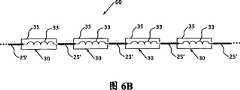
图6A是根据本发明的又一备选实施例的电导线60的示意图。电导线60包括多个电线节段25’,在此实施例中,每个节段都由多导体式电线组成,优选地以柔性表层绝缘的多导体式电线或同轴电缆的形式出现。所述电导线60和图1所示的电导线5相似,其包括一个或多个屏蔽的RF扼流圈30,扼流圈包括外面环绕着一层如上所述屏蔽材料层35的电感33。优选的是,如图6B所示,电导线60包括多个按上述与图1相关联的间隙隔开的屏蔽的RF扼流圈30。如图6A和6B所示,每个屏蔽的RF扼流圈30的每个电感33的第一端电连接到相邻电线节段对25’的其中一个节段上,而每个屏蔽的RF扼流圈30的电感33的另一端电连接到该相邻电线节段对25’的另一个节段上。此外,应该理解,在本实施例的多种变化形式中,可能提供如图3所示的额外的一层或多层屏蔽材料层,可能如图4所示在屏蔽的RF扼流圈中提供芯40,及/或可能使用如图5所示的环形RF扼流圈47。Figure 6A is a schematic diagram of an
图7是根据本发明的又一备选实施例的电导线60’的示意图,该电导线和图6所示的电导线60相似。电导线60’和电导线60的区别在于,在相邻电线节段对25’之间提供的不是单个屏蔽的RF扼流圈30,而是多个屏蔽的RF扼流圈30。特别地,如图7所示,对每个包含在电线节段25’中的导体提供了一个屏蔽的RF扼流圈30。图8是根据本发明的又一备选实施例的电导线60”的示意图,该电导线和图6所示的电导线60相似,除了每个屏蔽的RF扼流圈30都被如图5所示的环形屏蔽的RF扼流圈47所取代。FIG. 7 is a schematic diagram of an electrical lead 60' similar to the
图9A和9B分别是根据本发明的又一备选实施例的电导线65A和65B的示意图。如图9A所示,电导线65A包括多个电线节段25’,每个节段都由多导体式电线组成,其形式优选地为柔性表层绝缘的多导体式电线。如本文中其它地方所提,所述多导体式电线,或其中的每个导体可以是,例如,但不限于,同轴电线或三轴电线。电导线65A包括一个或多个备选的屏蔽RF扼流圈67,这些扼流圈优选地按上述与图1相关的间隔隔开。如图9A所示,每个屏蔽的RF扼流圈6A都包括一层如上所述的屏蔽材料35,这层材料覆盖位于相邻电线节段对25’之间的导体部分75,但不与其接触,而在每个此类导体75和所述屏蔽材料层35之间设有电容70。此外,在屏蔽的RF扼流圈67A中,在每个导体75和电线节段25’之间有电感33,其中电线节段25’在电气上从连接到电容70的点上流(电流方面)至导体75。在图9A所示的实施例中,电容70是调谐过的。图9B中所示的电导线65B和65A相似,除了在电导线65B中,在每个导体75和电线节段25’之间有电感33,其中电线节段在电气上从连接电容70的点下流(电流方面)至导体75。在电导线65B中,电容70在相对较高的频率(大约100MHz)下短路,从而没有信号由导线65B传输,并从而没有信号提供给图2所示的位置20(例如脑部和其它身体内的器官或组织)。作为备选,在电导线65A或65B中,电感33可缠绕在一起。9A and 9B are schematic diagrams of
图10是图6所示的实施例的一个变化形式,其中围绕电线节段25’和屏蔽的RF扼流圈30,除了那些必须保持暴露的区域,以便使用电导线60的可植入装置能够正常工作(如已知的,一些可植入装置,例如起搏器,需要导线的一个或多个部分暴露,以便可以和身体进行一处或多处电连接),其它都有绝缘材料层80,例如,但不限于,特氟纶,聚乙烯,尼龙,橡胶或PVC。这层绝缘材料80会提供更多的安全性,因为电荷可能会在屏蔽材料层35的边缘聚集。所述绝缘材料层80的使用不仅仅限于电导线60,还可用于此处所示的其它实施例。此外,当电导线60(或此处描述的其它电导线)用于可植入装置时,所述绝缘材料层80还可覆盖发生器15(图2)。FIG. 10 is a variation of the embodiment shown in FIG. 6 in which the
本发明对电导线5的性能进行了若干次模拟。模拟结果如图11A和11B所描绘。图11A显示了在普通电线和导线5上产生的感应电流的归一化曲线。图11B显示了在普通电线和导线5表面上的SAR分布。从这些模拟来看,很明显导线5能够把一根电线分成两根电线。The present invention simulates the performance of the
此外,为了评估本发明的有效性,针对一个包括电导线5的起搏器和一个普通起搏器进行了凝胶模型实验。凝胶模型的设置如图12所示,并在每种情况下在起搏器导线的末端包括一个温度探头1,以及一个参比探头2。图12所示的每个起搏器(普通起搏器和安全起搏器,即,包括导线5的起搏器)的凝胶模型设置都被进行MRI扫描,探头所测得的温度曲线如图13所示。如图所示,包括导线5的起搏器出现的发热明显小得多。Furthermore, in order to evaluate the effectiveness of the present invention, a gel model experiment was performed on a pacemaker including the
虽然本发明的优选实施例已如上进行描述和图解说明,但应该理解,这些都是本发明的示范例,而不能被认为是本发明的限制。例如,此处所包含的描述的主体将成组开关10描述成用于唤醒处理单元15。应该理解所述成组开关10可被用于唤醒任何类型的能够进入非活动睡眠状态的电子装置。在不背离本发明的精神或范围的前提下,可对本发明进行添加,删除,替换以及其他的更改。因此,本发明不应被认为仅限于前面的描述,而只受所附权利要求的范围限制。While preferred embodiments of the invention have been described and illustrated above, it should be understood that these are exemplary of the invention and are not to be considered as limitations of the invention. For example, the body of the description contained herein describes
Claims (55)
Applications Claiming Priority (3)
| Application Number | Priority Date | Filing Date | Title |
|---|---|---|---|
| US67741805P | 2005-05-04 | 2005-05-04 | |
| US60/677,418 | 2005-05-04 | ||
| PCT/US2006/017362WO2006119492A2 (en) | 2005-05-04 | 2006-05-04 | Improved electrical lead for an electronic device such as an implantable device |
Publications (2)
| Publication Number | Publication Date |
|---|---|
| CN101553165A CN101553165A (en) | 2009-10-07 |
| CN101553165Btrue CN101553165B (en) | 2011-05-18 |
Family
ID=37308740
Family Applications (1)
| Application Number | Title | Priority Date | Filing Date |
|---|---|---|---|
| CN2006800242837AExpired - Fee RelatedCN101553165B (en) | 2005-05-04 | 2006-05-04 | Electrical lead for an electronic device such as an implantable device |
Country Status (6)
| Country | Link |
|---|---|
| US (4) | US7561906B2 (en) |
| EP (1) | EP1878091B1 (en) |
| CN (1) | CN101553165B (en) |
| CA (1) | CA2606824C (en) |
| ES (1) | ES2623366T3 (en) |
| WO (1) | WO2006119492A2 (en) |
Cited By (3)
| Publication number | Priority date | Publication date | Assignee | Title |
|---|---|---|---|---|
| US9504822B2 (en) | 2012-10-18 | 2016-11-29 | Cardiac Pacemakers, Inc. | Inductive element for providing MRI compatibility in an implantable medical device lead |
| US9504821B2 (en) | 2014-02-26 | 2016-11-29 | Cardiac Pacemakers, Inc. | Construction of an MRI-safe tachycardia lead |
| US9750944B2 (en) | 2009-12-30 | 2017-09-05 | Cardiac Pacemakers, Inc. | MRI-conditionally safe medical device lead |
Families Citing this family (111)
| Publication number | Priority date | Publication date | Assignee | Title |
|---|---|---|---|---|
| US8244370B2 (en)* | 2001-04-13 | 2012-08-14 | Greatbatch Ltd. | Band stop filter employing a capacitor and an inductor tank circuit to enhance MRI compatibility of active medical devices |
| US8256430B2 (en) | 2001-06-15 | 2012-09-04 | Monteris Medical, Inc. | Hyperthermia treatment and probe therefor |
| US8457760B2 (en) | 2001-04-13 | 2013-06-04 | Greatbatch Ltd. | Switched diverter circuits for minimizing heating of an implanted lead and/or providing EMI protection in a high power electromagnetic field environment |
| US9295828B2 (en) | 2001-04-13 | 2016-03-29 | Greatbatch Ltd. | Self-resonant inductor wound portion of an implantable lead for enhanced MRI compatibility of active implantable medical devices |
| US8437865B2 (en) | 2001-04-13 | 2013-05-07 | Greatbatch Ltd. | Shielded network for an active medical device implantable lead |
| US8977355B2 (en) | 2001-04-13 | 2015-03-10 | Greatbatch Ltd. | EMI filter employing a capacitor and an inductor tank circuit having optimum component values |
| WO2002083016A1 (en) | 2001-04-13 | 2002-10-24 | Surgi-Vision, Inc. | Systems and methods for magnetic-resonance-guided interventional procedures |
| EP1776040A4 (en)* | 2004-08-09 | 2012-02-15 | Univ Johns Hopkins | IMPLANTABLE MRI-COMPATIBLE PACING AND ANTENNAS AND ASSOCIATED SYSTEMS AND METHODS |
| CA2606824C (en)* | 2005-05-04 | 2015-11-24 | Surgi-Vision, Inc. | Improved electrical lead for an electronic device such as an implantable device |
| CA2623453C (en) | 2005-10-21 | 2016-02-09 | Surgi-Vision, Inc. | Mri-safe high impedance lead systems and related methods |
| CA2623616A1 (en) | 2005-11-29 | 2007-06-07 | Surgi-Vision, Inc. | Mri-guided localization and/or lead placement systems, related methods, devices and computer program products |
| US9901731B2 (en)* | 2006-01-31 | 2018-02-27 | Medtronic, Inc. | Medical electrical lead having improved inductance |
| US7933662B2 (en) | 2006-04-26 | 2011-04-26 | Marshall Mark T | Medical electrical lead including an inductance augmenter |
| US9468750B2 (en) | 2006-11-09 | 2016-10-18 | Greatbatch Ltd. | Multilayer planar spiral inductor filter for medical therapeutic or diagnostic applications |
| US9827415B2 (en) | 2006-11-09 | 2017-11-28 | Greatbatch Ltd. | Implantable lead having multi-planar spiral inductor filter |
| US8239041B2 (en) | 2010-08-02 | 2012-08-07 | Greatbatch Ltd. | Multilayer helical wave filter for medical therapeutic or diagnostic applications |
| US7610101B2 (en)* | 2006-11-30 | 2009-10-27 | Cardiac Pacemakers, Inc. | RF rejecting lead |
| WO2008115426A1 (en)* | 2007-03-19 | 2008-09-25 | Boston Scientific Neuromodulation Corporation | Mri and rf compatible leads and related methods of operating and fabricating leads |
| ES2605170T3 (en) | 2007-03-19 | 2017-03-13 | Boston Scientific Neuromodulation Corporation | Cable manufacturing procedures and apparatus with conductors and related flexible cable configurations |
| US8175677B2 (en)* | 2007-06-07 | 2012-05-08 | MRI Interventions, Inc. | MRI-guided medical interventional systems and methods |
| US8315689B2 (en) | 2007-09-24 | 2012-11-20 | MRI Interventions, Inc. | MRI surgical systems for real-time visualizations using MRI image data and predefined data of surgical tools |
| US8195272B2 (en) | 2007-09-24 | 2012-06-05 | MRI Interventions, Inc. | MRI-compatible patches and methods for using the same |
| CA2700523A1 (en)* | 2007-09-24 | 2009-04-02 | Surgivision, Inc. | Mri-guided medical interventional systems and methods |
| WO2009067205A1 (en)* | 2007-11-21 | 2009-05-28 | Surgi-Vision, Inc. | Methods, systems and computer program products for positioning a guidance apparatus relative to a patient |
| US20090179716A1 (en)* | 2008-01-09 | 2009-07-16 | Anaren, Inc. | RF Filter Device |
| WO2009100003A1 (en) | 2008-02-06 | 2009-08-13 | Cardiac Pacemakers, Inc. | Lead with mri compatible design features |
| US8255055B2 (en)* | 2008-02-11 | 2012-08-28 | Cardiac Pacemakers, Inc. | MRI shielding in electrodes using AC pacing |
| US9108066B2 (en) | 2008-03-20 | 2015-08-18 | Greatbatch Ltd. | Low impedance oxide resistant grounded capacitor for an AIMD |
| US10080889B2 (en) | 2009-03-19 | 2018-09-25 | Greatbatch Ltd. | Low inductance and low resistance hermetically sealed filtered feedthrough for an AIMD |
| EP2110156B1 (en)* | 2008-04-14 | 2016-11-02 | Biotronik CRM Patent AG | Field decoupling element for use with an implantable lead and implantable medical device |
| US8103360B2 (en) | 2008-05-09 | 2012-01-24 | Foster Arthur J | Medical lead coil conductor with spacer element |
| US9513443B2 (en)* | 2008-05-28 | 2016-12-06 | John Lawrence Erb | Optical fiber-fine wire conductor and connectors |
| US8320990B2 (en)* | 2008-09-12 | 2012-11-27 | MRI Interventions, Inc. | Intrabody MRI stacked flat loop antennas and related systems |
| US8364279B2 (en) | 2008-09-25 | 2013-01-29 | Boston Scientific Neuromodulation Corporation | Electrical stimulation leads having RF compatibility and methods of use and manufacture |
| US8335570B2 (en) | 2008-10-09 | 2012-12-18 | Boston Scientific Neuromodulation Corporation | Electrical stimulation leads having RF compatibility and methods of use and manufacture |
| WO2010044019A1 (en)* | 2008-10-15 | 2010-04-22 | Koninklijke Philips Electronics N.V. | Probe for an implantable medical device |
| US20100106215A1 (en)* | 2008-10-23 | 2010-04-29 | Stubbs Scott R | Systems and methods to detect implantable medical device configuaration changes affecting mri conditional safety |
| US8634931B2 (en)* | 2008-10-30 | 2014-01-21 | Pacesetter, Inc. | MRI compatible implantable medical lead and method of making same |
| US20100137704A1 (en)* | 2008-12-02 | 2010-06-03 | Surgivision, Inc. | Medical mats with electrical paths and methods for using the same |
| US8294461B2 (en)* | 2009-01-15 | 2012-10-23 | The Board Of Trustees Of The Leland Stanford Junior University | Reverse circularly polarized non-tissue damaging RF in MRI detection of coupled RF current producing objects in a body |
| WO2010096179A2 (en)* | 2009-02-20 | 2010-08-26 | Surgivision, Inc. | Cable management systems for mri systems and related methods |
| US20100217115A1 (en)* | 2009-02-25 | 2010-08-26 | Hushek Stephen G | Temperature sensing within a patient during mr imaging |
| US9084883B2 (en) | 2009-03-12 | 2015-07-21 | Cardiac Pacemakers, Inc. | Thin profile conductor assembly for medical device leads |
| US8910376B2 (en)* | 2009-05-27 | 2014-12-16 | Boston Scientific Neuromodulation Corporation | Systems and methods for forming an end of an elongated member of an electrical stimulation system |
| WO2010144402A2 (en) | 2009-06-08 | 2010-12-16 | Surgivision, Inc. | Mri-guided surgical systems with preset scan planes |
| CN102625670B (en) | 2009-06-16 | 2015-07-15 | 核磁共振成像介入技术有限公司 | MRI-guided devices and MRI-guided interventional systems that can track and generate dynamic visualizations of the devices in near real time |
| ES2547713T3 (en) | 2009-06-26 | 2015-10-08 | Cardiac Pacemakers, Inc. | Bypass of a medical device that includes a single-coil coil with improved torque transmission capacity and reduced RM heating |
| WO2011043898A2 (en)* | 2009-10-09 | 2011-04-14 | Cardiac Pacemakers, Inc. | Mri compatible medical device lead including transmission line notch filters |
| US9254380B2 (en) | 2009-10-19 | 2016-02-09 | Cardiac Pacemakers, Inc. | MRI compatible tachycardia lead |
| WO2011053199A1 (en) | 2009-10-30 | 2011-05-05 | St. Jude Medical Ab | A medical implantable lead |
| EP2496164B1 (en)* | 2009-11-02 | 2016-02-10 | Koninklijke Philips N.V. | Radio frequency ablation catheter and magnetic resonance imaging system comprising said ablation catheter |
| US8554338B2 (en)* | 2009-11-05 | 2013-10-08 | Pacesetter, Inc. | MRI-compatible implantable lead having a heat spreader and method of using same |
| US20110144722A1 (en)* | 2009-12-10 | 2011-06-16 | Pacesetter, Inc. | Mri-compatible implantable lead with improved lc resonant component |
| US20110152990A1 (en)* | 2009-12-22 | 2011-06-23 | Pacesetter, Inc. | Mri compatible lead employing multiple miniature inductors |
| US8406895B2 (en)* | 2009-12-30 | 2013-03-26 | Cardiac Pacemakers, Inc. | Implantable electrical lead including a cooling assembly to dissipate MRI induced electrode heat |
| US8306630B2 (en)* | 2009-12-30 | 2012-11-06 | Cardiac Pacemakers, Inc. | Apparatus to selectively increase medical device lead inner conductor inductance |
| US8391994B2 (en) | 2009-12-31 | 2013-03-05 | Cardiac Pacemakers, Inc. | MRI conditionally safe lead with low-profile multi-layer conductor for longitudinal expansion |
| WO2011081713A1 (en) | 2009-12-31 | 2011-07-07 | Cardiac Pacemakers, Inc. | Mri conditionally safe lead with multi-layer conductor |
| US8825181B2 (en) | 2010-08-30 | 2014-09-02 | Cardiac Pacemakers, Inc. | Lead conductor with pitch and torque control for MRI conditionally safe use |
| US8831740B2 (en) | 2010-11-02 | 2014-09-09 | Pacesetter, Inc. | Implantable lead assembly having a plurality of inductors |
| US20120130460A1 (en)* | 2010-11-22 | 2012-05-24 | Pacesetter, Inc. | Hybrid implantable lead assembly |
| US8942825B2 (en) | 2010-12-17 | 2015-01-27 | Biotronik Se & Co. Kg | Implantable device with elongated electrical conductor |
| EP2476455A1 (en)* | 2011-01-13 | 2012-07-18 | BIOTRONIK SE & Co. KG | Implantable electrode lead |
| US8612021B2 (en) | 2011-02-10 | 2013-12-17 | Medtronic, Inc. | Magnetic resonance imaging compatible medical electrical lead and method of making the same |
| US10272252B2 (en) | 2016-11-08 | 2019-04-30 | Greatbatch Ltd. | Hermetic terminal for an AIMD having a composite brazed conductive lead |
| US10350421B2 (en) | 2013-06-30 | 2019-07-16 | Greatbatch Ltd. | Metallurgically bonded gold pocket pad for grounding an EMI filter to a hermetic terminal for an active implantable medical device |
| US9931514B2 (en) | 2013-06-30 | 2018-04-03 | Greatbatch Ltd. | Low impedance oxide resistant grounded capacitor for an AIMD |
| US10596369B2 (en) | 2011-03-01 | 2020-03-24 | Greatbatch Ltd. | Low equivalent series resistance RF filter for an active implantable medical device |
| US9427596B2 (en) | 2013-01-16 | 2016-08-30 | Greatbatch Ltd. | Low impedance oxide resistant grounded capacitor for an AIMD |
| US11198014B2 (en) | 2011-03-01 | 2021-12-14 | Greatbatch Ltd. | Hermetically sealed filtered feedthrough assembly having a capacitor with an oxide resistant electrical connection to an active implantable medical device housing |
| EP2734264B1 (en)* | 2011-07-22 | 2018-11-21 | Boston Scientific Scimed, Inc. | Nerve modulation system with a nerve modulation element positionable in a helical guide |
| EP2773420B1 (en)* | 2011-11-02 | 2016-10-26 | Boston Scientific Neuromodulation Corporation | Methods for making improved leads for electrical stimulation systems |
| US8666512B2 (en) | 2011-11-04 | 2014-03-04 | Cardiac Pacemakers, Inc. | Implantable medical device lead including inner coil reverse-wound relative to shocking coil |
| DE102011087117B4 (en)* | 2011-11-25 | 2023-07-20 | Hilti Aktiengesellschaft | Electric drive for a hand tool |
| US8600520B2 (en) | 2012-04-18 | 2013-12-03 | Pacesetter, Inc. | Implantable lead assembly having a plurality of inductors |
| AU2013249088B2 (en) | 2012-04-20 | 2015-12-03 | Cardiac Pacemakers, Inc. | Implantable medical device lead including a unifilar coiled cable |
| US8954168B2 (en) | 2012-06-01 | 2015-02-10 | Cardiac Pacemakers, Inc. | Implantable device lead including a distal electrode assembly with a coiled component |
| EP2866723A4 (en) | 2012-06-27 | 2016-12-14 | Monteris Medical Corp | GUIDED THERAPY BY IMAGE OF A FABRIC |
| JP6069499B2 (en) | 2012-08-31 | 2017-02-01 | カーディアック ペースメイカーズ, インコーポレイテッド | Lead wire with low peak MRI heating |
| US9192446B2 (en) | 2012-09-05 | 2015-11-24 | MRI Interventions, Inc. | Trajectory guide frame for MRI-guided surgeries |
| USRE46699E1 (en) | 2013-01-16 | 2018-02-06 | Greatbatch Ltd. | Low impedance oxide resistant grounded capacitor for an AIMD |
| US9078588B2 (en) | 2013-03-08 | 2015-07-14 | MRI Interventions, Inc. | MRI compatible intrabody stylets and related methods and systems |
| EP2835148A1 (en) | 2013-08-04 | 2015-02-11 | Greatbatch Ltd. | Multilayer planar spiral inductor filter for medical, therapeutic or diagnostic applications |
| US10279172B1 (en) | 2013-09-09 | 2019-05-07 | Pinnacle Bionics, Inc. | MRI compatible lead |
| WO2015196164A2 (en) | 2014-06-21 | 2015-12-23 | Accelemed, Llc | Method and apparatus for neuromodulation treatments of pain and other conditions |
| US20150265353A1 (en) | 2014-03-18 | 2015-09-24 | Monteris Medical Corporation | Image-guided therapy of a tissue |
| US10675113B2 (en) | 2014-03-18 | 2020-06-09 | Monteris Medical Corporation | Automated therapy of a three-dimensional tissue region |
| US9433383B2 (en) | 2014-03-18 | 2016-09-06 | Monteris Medical Corporation | Image-guided therapy of a tissue |
| JP6408131B2 (en)* | 2014-04-25 | 2018-10-17 | ボストン サイエンティフィック ニューロモデュレイション コーポレイション | System and method for electrical pulse charge compensation for implantable medical device capacitance loading effects |
| US9782581B2 (en) | 2014-06-27 | 2017-10-10 | Boston Scientific Neuromodulation Corporation | Methods and systems for electrical stimulation including a shielded sheath |
| WO2016160423A1 (en) | 2015-03-27 | 2016-10-06 | Boston Scientific Neuromodulation Corporation | Systems and methods for making and using electrical stimulation systems to reduce rf-induced tissue heating |
| US10327830B2 (en) | 2015-04-01 | 2019-06-25 | Monteris Medical Corporation | Cryotherapy, thermal therapy, temperature modulation therapy, and probe apparatus therefor |
| WO2016176645A1 (en) | 2015-04-30 | 2016-11-03 | Boston Scientific Neuromodulation Corporation | Electrical stimulation leads and systems having a rf shield along at least the lead and methods of making and using |
| US10185002B2 (en) | 2015-06-04 | 2019-01-22 | General Electric Company | Systems and methods for MRI common mode traps |
| EP3344133B1 (en)* | 2015-09-03 | 2024-04-24 | Mirtle Medical, LLC | Mri-compatible 12-lead ecg cable |
| US11206966B2 (en) | 2016-02-01 | 2021-12-28 | Intuitive Surgical Operations, Inc. | Reduction of endoscope high frequency leakage current using a common-mode choke |
| WO2017165410A1 (en) | 2016-03-21 | 2017-09-28 | Nalu Medical, Inc. | Devices and methods for positioning external devices in relation to implanted devices |
| EP3484577B1 (en) | 2016-07-18 | 2025-06-18 | Nalu Medical, Inc. | Systems for treating pelvic disorders and pain conditions |
| JP2019531787A (en) | 2016-08-30 | 2019-11-07 | ザ リージェンツ オブ ザ ユニバーシティ オブ カリフォルニア | Biomedical targeting and delivery method and apparatus and system for performing the same |
| US10249415B2 (en) | 2017-01-06 | 2019-04-02 | Greatbatch Ltd. | Process for manufacturing a leadless feedthrough for an active implantable medical device |
| WO2018156953A1 (en) | 2017-02-24 | 2018-08-30 | Nalu Medical, Inc. | Apparatus with sequentially implanted stimulators |
| US10905497B2 (en) | 2017-04-21 | 2021-02-02 | Clearpoint Neuro, Inc. | Surgical navigation systems |
| AU2018265016B2 (en) | 2017-05-09 | 2023-01-05 | Nalu Medical, Inc. | Stimulation apparatus |
| CN111132626B (en) | 2017-07-17 | 2024-01-30 | 沃雅戈治疗公司 | track array guidance system |
| CN110996788B (en) | 2017-08-07 | 2023-05-16 | 德普伊新特斯产品公司 | Folded MRI safety coil assembly |
| DE102019106675A1 (en) | 2018-03-20 | 2019-09-26 | Biotronik Se & Co. Kg | Lead for a medical implant, with integrated periodic induction coils (iPIC) for reduced interactions with electromagnetic fields |
| US10912945B2 (en) | 2018-03-22 | 2021-02-09 | Greatbatch Ltd. | Hermetic terminal for an active implantable medical device having a feedthrough capacitor partially overhanging a ferrule for high effective capacitance area |
| US10905888B2 (en) | 2018-03-22 | 2021-02-02 | Greatbatch Ltd. | Electrical connection for an AIMD EMI filter utilizing an anisotropic conductive layer |
| US11779280B2 (en)* | 2018-06-29 | 2023-10-10 | Biosense Webster (Israel) Ltd. | Reference wires to remove noise and artifacts in cardiac mapping catheter |
| RU205777U1 (en)* | 2020-06-30 | 2021-08-11 | Дмитрий Валерьевич Хачатуров | Communication device for measuring units of the telemetry system |
| EP4053578A1 (en)* | 2021-03-04 | 2022-09-07 | Koninklijke Philips N.V. | Cable harness with multiple rf chokes and magnetic resonance system |
Citations (3)
| Publication number | Priority date | Publication date | Assignee | Title |
|---|---|---|---|---|
| CN87210281U (en)* | 1987-07-17 | 1988-06-08 | 重庆电动工具厂 | Radio interference suppressor |
| US5246438A (en)* | 1988-11-25 | 1993-09-21 | Sensor Electronics, Inc. | Method of radiofrequency ablation |
| CN1483209A (en)* | 2000-12-20 | 2004-03-17 | С | Choke coil |
Family Cites Families (59)
| Publication number | Priority date | Publication date | Assignee | Title |
|---|---|---|---|---|
| US2130758A (en)* | 1935-06-01 | 1938-09-20 | E J Rose Mfg Company Of Califo | Electrode for diathermy treatment and the like |
| US3218638A (en)* | 1962-05-29 | 1965-11-16 | William M Honig | Wireless passive biological telemetry system |
| US4766381A (en)* | 1987-08-12 | 1988-08-23 | Vanderbilt University | Driven inversion spin echo magnetic resonance imaging |
| US5314458A (en)* | 1990-06-01 | 1994-05-24 | University Of Michigan | Single channel microstimulator |
| US5217010A (en) | 1991-05-28 | 1993-06-08 | The Johns Hopkins University | Ecg amplifier and cardiac pacemaker for use during magnetic resonance imaging |
| US5281914A (en)* | 1991-08-09 | 1994-01-25 | The Johns Hopkins University | Method of vector magnetic resonance measurement and imaging and associated apparatus |
| US5352979A (en)* | 1992-08-07 | 1994-10-04 | Conturo Thomas E | Magnetic resonance imaging with contrast enhanced phase angle reconstruction |
| US5817136A (en) | 1997-05-02 | 1998-10-06 | Pacesetter, Inc. | Rate-responsive pacemaker with minute volume determination and EMI protection |
| US6408202B1 (en)* | 1998-11-03 | 2002-06-18 | The Johns Hopkins University | Transesophageal magnetic resonance analysis method and apparatus |
| US9061139B2 (en)* | 1998-11-04 | 2015-06-23 | Greatbatch Ltd. | Implantable lead with a band stop filter having a capacitor in parallel with an inductor embedded in a dielectric body |
| US6701176B1 (en)* | 1998-11-04 | 2004-03-02 | Johns Hopkins University School Of Medicine | Magnetic-resonance-guided imaging, electrophysiology, and ablation |
| US8244370B2 (en)* | 2001-04-13 | 2012-08-14 | Greatbatch Ltd. | Band stop filter employing a capacitor and an inductor tank circuit to enhance MRI compatibility of active medical devices |
| US7844319B2 (en)* | 1998-11-04 | 2010-11-30 | Susil Robert C | Systems and methods for magnetic-resonance-guided interventional procedures |
| US6284971B1 (en)* | 1998-11-25 | 2001-09-04 | Johns Hopkins University School Of Medicine | Enhanced safety coaxial cables |
| US6188219B1 (en)* | 1999-01-22 | 2001-02-13 | The Johns Hopkins University | Magnetic resonance imaging method and apparatus and method of calibrating the same |
| US6539253B2 (en) | 2000-08-26 | 2003-03-25 | Medtronic, Inc. | Implantable medical device incorporating integrated circuit notch filters |
| US6949929B2 (en)* | 2003-06-24 | 2005-09-27 | Biophan Technologies, Inc. | Magnetic resonance imaging interference immune device |
| US8977355B2 (en)* | 2001-04-13 | 2015-03-10 | Greatbatch Ltd. | EMI filter employing a capacitor and an inductor tank circuit having optimum component values |
| US7853325B2 (en)* | 2001-04-13 | 2010-12-14 | Greatbatch Ltd. | Cylindrical bandstop filters for medical lead systems |
| US8509913B2 (en)* | 2001-04-13 | 2013-08-13 | Greatbatch Ltd. | Switched diverter circuits for minimizing heating of an implanted lead and/or providing EMI protection in a high power electromagnetic field environment |
| US8849403B2 (en)* | 2001-04-13 | 2014-09-30 | Greatbatch Ltd. | Active implantable medical system having EMI shielded lead |
| US8457760B2 (en)* | 2001-04-13 | 2013-06-04 | Greatbatch Ltd. | Switched diverter circuits for minimizing heating of an implanted lead and/or providing EMI protection in a high power electromagnetic field environment |
| US7787958B2 (en)* | 2001-04-13 | 2010-08-31 | Greatbatch Ltd. | RFID detection and identification system for implantable medical lead systems |
| US8219208B2 (en)* | 2001-04-13 | 2012-07-10 | Greatbatch Ltd. | Frequency selective passive component networks for active implantable medical devices utilizing an energy dissipating surface |
| US8000801B2 (en)* | 2001-04-13 | 2011-08-16 | Greatbatch Ltd. | System for terminating abandoned implanted leads to minimize heating in high power electromagnetic field environments |
| US8600519B2 (en)* | 2001-04-13 | 2013-12-03 | Greatbatch Ltd. | Transient voltage/current protection system for electronic circuits associated with implanted leads |
| WO2002083016A1 (en)* | 2001-04-13 | 2002-10-24 | Surgi-Vision, Inc. | Systems and methods for magnetic-resonance-guided interventional procedures |
| US8989870B2 (en)* | 2001-04-13 | 2015-03-24 | Greatbatch Ltd. | Tuned energy balanced system for minimizing heating and/or to provide EMI protection of implanted leads in a high power electromagnetic field environment |
| US7899551B2 (en)* | 2001-04-13 | 2011-03-01 | Greatbatch Ltd. | Medical lead system utilizing electromagnetic bandstop filters |
| US7916013B2 (en)* | 2005-03-21 | 2011-03-29 | Greatbatch Ltd. | RFID detection and identification system for implantable medical devices |
| US20070088416A1 (en)* | 2001-04-13 | 2007-04-19 | Surgi-Vision, Inc. | Mri compatible medical leads |
| US8437865B2 (en)* | 2001-04-13 | 2013-05-07 | Greatbatch Ltd. | Shielded network for an active medical device implantable lead |
| US6944489B2 (en)* | 2001-10-31 | 2005-09-13 | Medtronic, Inc. | Method and apparatus for shunting induced currents in an electrical lead |
| US20030144720A1 (en)* | 2002-01-29 | 2003-07-31 | Villaseca Eduardo H. | Electromagnetic trap for a lead |
| US6985775B2 (en)* | 2002-01-29 | 2006-01-10 | Medtronic, Inc. | Method and apparatus for shunting induced currents in an electrical lead |
| US7917219B2 (en)* | 2002-02-28 | 2011-03-29 | Greatbatch Ltd. | Passive electronic network components designed for direct body fluid exposure |
| US8660645B2 (en)* | 2002-02-28 | 2014-02-25 | Greatbatch Ltd. | Electronic network components utilizing biocompatible conductive adhesives for direct body fluid exposure |
| EP1488434B1 (en)* | 2002-02-28 | 2012-12-12 | Greatbatch Ltd. | Emi feedthrough filter terminal assembly utilizing hermetic seal for electrical attachment between lead wires and capacitor |
| US6985347B2 (en)* | 2002-02-28 | 2006-01-10 | Greatbatch-Sierra, Inc. | EMI filter capacitors designed for direct body fluid exposure |
| US6987660B2 (en)* | 2003-02-27 | 2006-01-17 | Greatbatch-Sierra, Inc. | Spring contact system for EMI filtered hermetic seals for active implantable medical devices |
| US7038900B2 (en) | 2003-02-27 | 2006-05-02 | Greatbatch-Sierra, Inc. | EMI filter terminal assembly with wire bond pads for human implant applications |
| US6999818B2 (en)* | 2003-05-23 | 2006-02-14 | Greatbatch-Sierra, Inc. | Inductor capacitor EMI filter for human implant applications |
| US7623335B2 (en)* | 2003-02-27 | 2009-11-24 | Greatbatch-Sierra, Inc | Hermetic feedthrough terminal assembly with wire bond pads for human implant applications |
| US6980863B2 (en)* | 2003-03-20 | 2005-12-27 | Medtronic, Inc. | Neurological stimulation lead extension |
| US20040199069A1 (en)* | 2003-04-02 | 2004-10-07 | Connelly Patrick R. | Device and method for preventing magnetic resonance imaging induced damage |
| US7039950B2 (en) | 2003-04-21 | 2006-05-02 | Ipolicy Networks, Inc. | System and method for network quality of service protection on security breach detection |
| US7765005B2 (en)* | 2004-02-12 | 2010-07-27 | Greatbatch Ltd. | Apparatus and process for reducing the susceptability of active implantable medical devices to medical procedures such as magnetic resonance imaging |
| US7035076B1 (en)* | 2005-08-15 | 2006-04-25 | Greatbatch-Sierra, Inc. | Feedthrough filter capacitor assembly with internally grounded hermetic insulator |
| US7489495B2 (en)* | 2004-04-15 | 2009-02-10 | Greatbatch-Sierra, Inc. | Apparatus and process for reducing the susceptibility of active implantable medical devices to medical procedures such as magnetic resonance imaging |
| US7035077B2 (en)* | 2004-05-10 | 2006-04-25 | Greatbatch-Sierra, Inc. | Device to protect an active implantable medical device feedthrough capacitor from stray laser weld strikes, and related manufacturing process |
| US7136273B2 (en)* | 2005-03-30 | 2006-11-14 | Greatbatch-Sierra, Inc. | Hybrid spring contact system for EMI filtered hermetic seals for active implantable medical devices |
| CA2606824C (en) | 2005-05-04 | 2015-11-24 | Surgi-Vision, Inc. | Improved electrical lead for an electronic device such as an implantable device |
| EP1945297B1 (en)* | 2005-11-11 | 2016-08-10 | Greatbatch Ltd. | Tank filters placed in series with the lead wires or circuits of active medical devices to enhance mri compatibility |
| US7853324B2 (en)* | 2005-11-11 | 2010-12-14 | Greatbatch Ltd. | Tank filters utilizing very low K materials, in series with lead wires or circuits of active medical devices to enhance MRI compatibility |
| US20070123949A1 (en)* | 2005-11-11 | 2007-05-31 | Greatbatch Ltd. | Low loss band pass filter for rf distance telemetry pin antennas of active implantable medical devices |
| US20100191306A1 (en)* | 2006-01-25 | 2010-07-29 | Greatbatch Ltd. | Transient voltage suppression circuit for an implanted rfid chip |
| US8248232B2 (en)* | 2006-01-25 | 2012-08-21 | Greatbatch Ltd. | Hermetically sealed RFID microelectronic chip connected to a biocompatible RFID antenna |
| US8253555B2 (en)* | 2006-01-25 | 2012-08-28 | Greatbatch Ltd. | Miniature hermetically sealed RFID microelectronic chip connected to a biocompatible RFID antenna for use in conjunction with an AIMD |
| EP2291219B1 (en)* | 2008-06-23 | 2017-10-25 | Greatbatch Ltd. | Frequency selective passive component networks for implantable leads of active implantable medical devices utilizing an energy dissipating surface |
- 2006
- 2006-05-04CACA2606824Apatent/CA2606824C/enactiveActive
- 2006-05-04ESES06759133.9Tpatent/ES2623366T3/enactiveActive
- 2006-05-04CNCN2006800242837Apatent/CN101553165B/ennot_activeExpired - Fee Related
- 2006-05-04WOPCT/US2006/017362patent/WO2006119492A2/enactiveApplication Filing
- 2006-05-04USUS11/417,594patent/US7561906B2/enactiveActive
- 2006-05-04EPEP06759133.9Apatent/EP1878091B1/enactiveActive
- 2009
- 2009-06-04USUS12/478,145patent/US7957783B2/enactiveActive
- 2011
- 2011-05-02USUS13/099,167patent/US8380277B2/enactiveActive
- 2013
- 2013-01-14USUS13/741,009patent/US8649842B2/enactiveActive
Patent Citations (3)
| Publication number | Priority date | Publication date | Assignee | Title |
|---|---|---|---|---|
| CN87210281U (en)* | 1987-07-17 | 1988-06-08 | 重庆电动工具厂 | Radio interference suppressor |
| US5246438A (en)* | 1988-11-25 | 1993-09-21 | Sensor Electronics, Inc. | Method of radiofrequency ablation |
| CN1483209A (en)* | 2000-12-20 | 2004-03-17 | С | Choke coil |
Cited By (4)
| Publication number | Priority date | Publication date | Assignee | Title |
|---|---|---|---|---|
| US9750944B2 (en) | 2009-12-30 | 2017-09-05 | Cardiac Pacemakers, Inc. | MRI-conditionally safe medical device lead |
| US9504822B2 (en) | 2012-10-18 | 2016-11-29 | Cardiac Pacemakers, Inc. | Inductive element for providing MRI compatibility in an implantable medical device lead |
| US9504821B2 (en) | 2014-02-26 | 2016-11-29 | Cardiac Pacemakers, Inc. | Construction of an MRI-safe tachycardia lead |
| US9682231B2 (en) | 2014-02-26 | 2017-06-20 | Cardiac Pacemakers, Inc. | Construction of an MRI-safe tachycardia lead |
Also Published As
| Publication number | Publication date |
|---|---|
| US20110218422A1 (en) | 2011-09-08 |
| US7957783B2 (en) | 2011-06-07 |
| CA2606824A1 (en) | 2006-11-09 |
| CN101553165A (en) | 2009-10-07 |
| US20060252314A1 (en) | 2006-11-09 |
| US8649842B2 (en) | 2014-02-11 |
| US7561906B2 (en) | 2009-07-14 |
| US8380277B2 (en) | 2013-02-19 |
| CA2606824C (en) | 2015-11-24 |
| EP1878091A2 (en) | 2008-01-16 |
| US20130178924A1 (en) | 2013-07-11 |
| WO2006119492A3 (en) | 2009-04-30 |
| EP1878091B1 (en) | 2017-02-22 |
| EP1878091A4 (en) | 2011-01-26 |
| ES2623366T3 (en) | 2017-07-11 |
| WO2006119492A2 (en) | 2006-11-09 |
| US20090254152A1 (en) | 2009-10-08 |
Similar Documents
| Publication | Publication Date | Title |
|---|---|---|
| CN101553165B (en) | Electrical lead for an electronic device such as an implantable device | |
| US8849403B2 (en) | Active implantable medical system having EMI shielded lead | |
| US8634931B2 (en) | MRI compatible implantable medical lead and method of making same | |
| US8285396B2 (en) | MRI compatible electrical lead for an implanted electronic medical device | |
| US7917213B2 (en) | MRI compatible implanted electronic medical lead | |
| CN101325985B (en) | Bandstop filters applying capacitor and inductor tank circuits to improve magnetic resonance imaging compatibility of active medical devices | |
| US8483840B2 (en) | Dual function tuned L-C input trap passive EMI filter component network for an active implantable medical device | |
| JP5430671B2 (en) | Lead wire with high surface resistance | |
| US8239040B2 (en) | Electrode catheter for intervention purposes | |
| US20090270956A1 (en) | Implantable medical lead configured for improved mri safety | |
| US8369964B2 (en) | MRI compatible medical device lead including transmission line notch filters | |
| US20080154348A1 (en) | Mri compatible implantable devices | |
| EP2079522A1 (en) | Mri compatible implanted electronic medical device with power and data communication capability | |
| EP2373377B1 (en) | A medical implantable lead | |
| US20110301676A1 (en) | Reducing resonant currents in a resonating circuit during mri scans | |
| US20140052203A1 (en) | Mri compatible implantable electronic medical lead | |
| US9101757B2 (en) | Implantable lead having an elongated lead body | |
| US20120130460A1 (en) | Hybrid implantable lead assembly | |
| WO2019161324A1 (en) | Mri-safe implantable leads with high-dielectric coating |
Legal Events
| Date | Code | Title | Description |
|---|---|---|---|
| C06 | Publication | ||
| PB01 | Publication | ||
| C10 | Entry into substantive examination | ||
| SE01 | Entry into force of request for substantive examination | ||
| C14 | Grant of patent or utility model | ||
| GR01 | Patent grant | ||
| CF01 | Termination of patent right due to non-payment of annual fee | ||
| CF01 | Termination of patent right due to non-payment of annual fee | Granted publication date:20110518 |