CN101547654B - Tissue Clips for Transanal Hemorrhoidoplasty or Hemorrhoidectomy - Google Patents
Tissue Clips for Transanal Hemorrhoidoplasty or HemorrhoidectomyDownload PDFInfo
- Publication number
- CN101547654B CN101547654BCN200780044748XACN200780044748ACN101547654BCN 101547654 BCN101547654 BCN 101547654BCN 200780044748X ACN200780044748X ACN 200780044748XACN 200780044748 ACN200780044748 ACN 200780044748ACN 101547654 BCN101547654 BCN 101547654B
- Authority
- CN
- China
- Prior art keywords
- proximal
- tissue
- nearside
- distal
- jaw
- Prior art date
- Legal status (The legal status is an assumption and is not a legal conclusion. Google has not performed a legal analysis and makes no representation as to the accuracy of the status listed.)
- Expired - Fee Related
Links
Images


Classifications
- A—HUMAN NECESSITIES
- A61—MEDICAL OR VETERINARY SCIENCE; HYGIENE
- A61B—DIAGNOSIS; SURGERY; IDENTIFICATION
- A61B17/00—Surgical instruments, devices or methods
- A61B17/28—Surgical forceps
- A61B17/29—Forceps for use in minimally invasive surgery
- A—HUMAN NECESSITIES
- A61—MEDICAL OR VETERINARY SCIENCE; HYGIENE
- A61B—DIAGNOSIS; SURGERY; IDENTIFICATION
- A61B17/00—Surgical instruments, devices or methods
- A61B17/11—Surgical instruments, devices or methods for performing anastomosis; Buttons for anastomosis
- A61B17/115—Staplers for performing anastomosis, e.g. in a single operation
- A61B17/1155—Circular staplers comprising a plurality of staples
- A—HUMAN NECESSITIES
- A61—MEDICAL OR VETERINARY SCIENCE; HYGIENE
- A61B—DIAGNOSIS; SURGERY; IDENTIFICATION
- A61B17/00—Surgical instruments, devices or methods
- A61B17/22—Implements for squeezing-off ulcers or the like on inner organs of the body; Implements for scraping-out cavities of body organs, e.g. bones; for invasive removal or destruction of calculus using mechanical vibrations; for removing obstructions in blood vessels, not otherwise provided for
- A61B17/22031—Gripping instruments, e.g. forceps, for removing or smashing calculi
- A—HUMAN NECESSITIES
- A61—MEDICAL OR VETERINARY SCIENCE; HYGIENE
- A61B—DIAGNOSIS; SURGERY; IDENTIFICATION
- A61B17/00—Surgical instruments, devices or methods
- A61B17/22—Implements for squeezing-off ulcers or the like on inner organs of the body; Implements for scraping-out cavities of body organs, e.g. bones; for invasive removal or destruction of calculus using mechanical vibrations; for removing obstructions in blood vessels, not otherwise provided for
- A61B2017/22072—Implements for squeezing-off ulcers or the like on inner organs of the body; Implements for scraping-out cavities of body organs, e.g. bones; for invasive removal or destruction of calculus using mechanical vibrations; for removing obstructions in blood vessels, not otherwise provided for with an instrument channel, e.g. for replacing one instrument by the other
- A—HUMAN NECESSITIES
- A61—MEDICAL OR VETERINARY SCIENCE; HYGIENE
- A61B—DIAGNOSIS; SURGERY; IDENTIFICATION
- A61B17/00—Surgical instruments, devices or methods
- A61B17/28—Surgical forceps
- A61B2017/2808—Clamp, e.g. towel clamp
- A—HUMAN NECESSITIES
- A61—MEDICAL OR VETERINARY SCIENCE; HYGIENE
- A61B—DIAGNOSIS; SURGERY; IDENTIFICATION
- A61B17/00—Surgical instruments, devices or methods
- A61B17/28—Surgical forceps
- A61B17/29—Forceps for use in minimally invasive surgery
- A61B17/2909—Handles
- A61B2017/2912—Handles transmission of forces to actuating rod or piston
- A—HUMAN NECESSITIES
- A61—MEDICAL OR VETERINARY SCIENCE; HYGIENE
- A61B—DIAGNOSIS; SURGERY; IDENTIFICATION
- A61B17/00—Surgical instruments, devices or methods
- A61B17/28—Surgical forceps
- A61B17/29—Forceps for use in minimally invasive surgery
- A61B2017/2946—Locking means
Landscapes
- Health & Medical Sciences (AREA)
- Surgery (AREA)
- Life Sciences & Earth Sciences (AREA)
- Medical Informatics (AREA)
- Animal Behavior & Ethology (AREA)
- Engineering & Computer Science (AREA)
- Biomedical Technology (AREA)
- Heart & Thoracic Surgery (AREA)
- Ophthalmology & Optometry (AREA)
- Molecular Biology (AREA)
- Nuclear Medicine, Radiotherapy & Molecular Imaging (AREA)
- General Health & Medical Sciences (AREA)
- Public Health (AREA)
- Veterinary Medicine (AREA)
- Surgical Instruments (AREA)
- Details Of Garments (AREA)
- Knitting Of Fabric (AREA)
- Woven Fabrics (AREA)
- Seasonings (AREA)
Abstract
Description
Translated fromChinese技术领域technical field
本发明总的涉及用于治疗痔疮的外科器械,更具体地,涉及一种组织夹具,该组织夹具能够使经肛门的痔疮修补术或痔疮切除术过程能够将内痔重新定位到它们的自然解剖学位置和/或将患有黏膜脱垂的患者体内的内痔的部分或者全部除去。The present invention relates generally to surgical instruments for the treatment of hemorrhoids, and more particularly, to a tissue clamp that enables transanal hemorrhoidoplasty or hemorrhoidectomy procedures to reposition internal hemorrhoids to their natural anatomy location and/or partial or total removal of internal hemorrhoids in patients with mucosal prolapse.
背景技术Background technique
痔疮(痔)由肛管周围的内部和/或外部静脉丛的充血引起,并以或多或少明显倾向于暂时或者永久脱垂在肛管外部为特征。与痔疮相关的症状包括疼痛、出血、瘙痒、排出粘液,并且在脱垂的组织无法被手动地放回到肛管内的情况下,脱垂的组织通常被勒束或者形成血栓。Hemorrhoids (hemorrhoids) are caused by congestion of the internal and/or external venous plexus around the anal canal and are characterized by a more or less pronounced tendency to prolapse temporarily or permanently outside the anal canal. Symptoms associated with hemorrhoids include pain, bleeding, itching, discharge of mucus, and where the prolapsed tissue cannot be manually placed back into the anal canal, the prolapsed tissue is often strangulated or thrombused.
尽管在很多情况下可以通过饮食调节、局部用药和温水浸泡来治疗痔疮,但这些方法仅暂时缓解疼痛和肿胀的症状,在一定比例的病例中,必须进行外科手术来提供满意的、长期的治疗。Although hemorrhoids can be treated in many cases with dietary modifications, topical medications, and warm water soaks, these provide only temporary relief of symptoms of pain and swelling, and in a proportion of cases, surgery is necessary to provide satisfactory, long-term treatment .
这些已知的外科手术传统上意味着要切除三个主要的痔疮脉管(痔疮切除术)。更新的一种方法被称为吻合器痔固定术或者黏膜环切术,其通过用圆形缝合装置切除一段脱垂的肛门黏膜来缓解痔疮组织的脱垂。These known surgical procedures traditionally imply the removal of the three main hemorrhoidal vessels (hemorrhoidectomy). A more recent procedure, known as stapled hemorrhoidopexy or circumcision, relieves prolapsed hemorrhoidal tissue by excising a section of prolapsed anal mucosa with a circular suturing device.
这种已知的圆形缝合装置包括具有近侧仓装置和能够相对于仓装置运动的远侧砧座的钉紧固组件。仓装置容纳钉和刀驱动机构,该钉和刀驱动机构适于将圆形刀和两个或者更多闭合的钉排推出仓装置的远端表面并且朝着砧座推动。砧座包括与仓装置的钉排和圆形刀匹配的钉成形表面和环形切割砧板,砧座适于与仓装置协作用于使离开仓装置的钉的端部成形,并用于利用圆形刀切除多余组织。为了将脱垂的肛门黏膜段定位在圆形缝合器的仓装置和砧座之间,必须围绕整个肛门周围设置荷包缝线并通过圆形缝合器的钉紧固组件的外壳内的缝线牵拉脱垂的组织。尽管利用已知的外科缝合器械是有益的并极大地便利了经肛门的痔疮修补术或者痔疮切除术的执行,但仍然有些问题。由于圆形缝合器的仓装置的妨碍,外科医生不能在视觉上控制牵拉到器械中的组织的位置和量。这导致直肠壁受损的风险增加,例如,当过多的肌肉组织被牵引到装置中并被切除时。并且,已知的圆形缝合器的结构使其很难接近肛管,并且待被切除的组织可能太大而不能被引入到缝合装置的外壳中。This known circular suturing device comprises a staple fastening assembly having a proximal cartridge device and a distal anvil movable relative to the cartridge device. The cartridge device houses a staple and knife drive mechanism adapted to push the circular knife and two or more closed rows of staples out of the distal surface of the cartridge device and toward the anvil. An anvil comprising a staple forming surface and an annular cutting anvil mated with the row of staples of the cartridge device and a circular knife, the anvil being adapted to cooperate with the cartridge device for shaping the ends of the staples exiting the cartridge device and for utilizing the circular knife Excess tissue is removed. In order to position the prolapsed anal mucosal segment between the cartridge assembly and the anvil of the circular stapler, a purse string suture must be placed around the entire anus and pulled through the suture within the housing of the circular stapler's staple fastening assembly Pull prolapsed tissue. While the use of known surgical stapling instruments is beneficial and greatly facilitates the performance of transanal hemorrhoid repairs or hemorrhoidectomy, there are still some problems. Due to the obstruction of the cartridge device of the circular stapler, the surgeon cannot visually control the location and amount of tissue pulled into the instrument. This leads to an increased risk of damage to the rectal wall, for example, when excess muscle tissue is drawn into the device and removed. Also, the structure of known circular staplers makes it difficult to access the anal canal, and the tissue to be resected may be too large to be introduced into the housing of the stapling device.
最后但很重要的是,圆形外科缝合器是结合并执行痔疮修补术的多种功能或者多个手术步骤、即组织定位(夹紧)、组织固定(缝合)和组织切除(切割)的相当复杂的器械。尽管这种单个装置的方法一般来说是期望的,但是这使器械的成本相当高,不能改变外科治疗痔疮的单个步骤,并且不能使用认为是对患者最适合的外科技术(例如,通过线缝合而不是钉缝合进行组织固定,或者通过射频或超声能量而不是环形切割来进行组织切除)。Last but not least, the circular surgical stapler is an equivalent tool that combines and performs multiple functions or multiple surgical steps of hemorrhoid repair, namely tissue positioning (clamping), tissue fixation (suturing) and tissue excision (cutting). complex apparatus. While this single-device approach is generally desirable, it makes the cost of the instrument considerably high, does not allow for modification of the individual steps in the surgical treatment of hemorrhoids, and does not allow the use of surgical techniques deemed most appropriate for the patient (e.g., suturing by suture). instead of staples for tissue fixation, or for tissue resection with radiofrequency or ultrasonic energy instead of circular cutting).
发明内容Contents of the invention
鉴于现有技术的缺点,本发明的目的是提供一种用于执行经肛门的痔疮修补术或者痔疮切除术的外科器械,其允许对待固定和切除的脱垂组织的位置和量进行良好的视觉控制,以使直肠壁受损的风险最小化。In view of the disadvantages of the prior art, it is an object of the present invention to provide a surgical instrument for performing transanal hemorrhoidoplasty or hemorrhoidectomy, which allows good visualization of the position and amount of prolapsed tissue to be fixed and excised controlled to minimize the risk of damage to the rectal wall.
在主要目的的总体范围内,本发明的另一个目的是提供一种用于执行经肛门的痔疮修补术或痔疮切除术的外科器械,其具有例如通过其它外科器械充分接近脱垂的组织以使外科医生能够自由地选择和更换施用到组织的外科技术的特征。Within the general scope of the main purpose, another object of the present invention is to provide a surgical instrument for performing transanal hemorrhoidoplasty or hemorrhoidectomy having sufficient access to prolapsed tissue, for example by other surgical instruments, to allow Surgeons are free to choose and change the characteristics of the surgical technique applied to the tissue.
本发明的又一个目的是提供一种用于执行经肛门的痔疮修补术或痔疮切除术的外科器械,其具有能够使器械的外部尺寸并不会限制待固定和切除的脱垂组织的体积的特征。Yet another object of the present invention is to provide a surgical instrument for performing transanal hemorrhoidoplasty or hemorrhoidectomy, which is of such a size that the external dimensions of the instrument do not limit the volume of prolapsed tissue to be fixed and excised. feature.
本发明的又一个目的是提供一种用于执行经肛门的痔疮修补术或痔疮切除术的外科器械,其具有与已知的圆形缝合器相比简单且成本经济的结构。Yet another object of the present invention is to provide a surgical instrument for performing transanal hemorrhoidoplasty or hemorrhoidectomy, which has a simple and cost-effective structure compared to known circular staplers.
这些和其它目的通过根据权利要求1所述的用于在经肛门的痔疮修补术或痔疮切除术过程中保持脱垂组织的一部分的外科组织夹具来实现。从属权利要求覆盖了本发明的有利实施方式。These and other objects are achieved by a surgical tissue clamp for holding a portion of prolapsed tissue during transanal hemorrhoidoplasty or hemorrhoidectomy according to
根据本发明,组织夹具包括:细长的插入轴、设置在插入轴的近端的手柄和设置在插入轴的远端的夹头。夹头包括近侧钳口和能够相对于近侧钳口运动的远侧钳口,该远侧钳口被构造成与近侧钳口相互协作用于以相对于夹头的纵向轴线基本径向的定向夹紧脱垂的组织。致动装置操作地与近侧钳口和远侧钳口连接,并适于使钳口靠近并将钳口保持在组织夹紧构型。夹头限定能够近侧地暴露被夹紧的组织的至少一个近侧接近孔,由此允许观察被夹紧的组织,并且如果需要,允许在被夹紧的组织被定位(例如被牵拉到夹头中)并被夹紧在钳口之间时通过另外的器械到达该组织。这使得获得脱垂的组织在夹具的钳口之间的精确定位成为可能,因此,使得获得良好适用到痔疮修补术或痔疮切除术的随后步骤(即,组织固定和切除)的夹紧线的精确定位成为可能。而且,近侧接近孔不仅近侧地暴露待夹紧的组织,而且允许脱垂组织的体积的至少一部分在其定位过程中被牵拉通过或者落入通过接近孔而从夹头出来,从而经受治疗的组织的体积并不会像已知的圆形缝合器那样受夹头的总体尺寸的限制。这对于具有较大混合痔的患者来说尤其有利。一旦脱垂的组织被夹紧在钳口之间,钳口就保持锁定在它们的夹紧构型,且现在可以用其它的器械容易地到达和操作组织,例如固定组织的外科缝线、钉、粘合剂或者超声装置,以及手术刀、解剖刀、剪和超声或者射频装置切除多余的组织体积。According to the present invention, the tissue clamp includes: an elongated insertion shaft, a handle disposed at the proximal end of the insertion shaft, and a collet disposed at the distal end of the insertion shaft. The collet includes a proximal jaw and a distal jaw movable relative to the proximal jaw, the distal jaw being configured to cooperate with the proximal jaw to move substantially radially with respect to the longitudinal axis of the collet. The directional clamping of the prolapsed tissue. An actuation device is operatively connected to the proximal and distal jaws and adapted to approximate and maintain the jaws in a tissue-gripping configuration. The chuck defines at least one proximal access hole capable of proximally exposing the clamped tissue, thereby allowing the clamped tissue to be viewed and, if desired, positioned (e.g., pulled into the clamped tissue). in the collet) and is accessed by additional instruments while being clamped between the jaws. This makes it possible to obtain a precise positioning of the prolapsed tissue between the jaws of the clamp, thus making it possible to obtain a clamping wire well suited to the subsequent steps of hemorrhoidoplasty or hemorrhoidectomy (i.e. tissue fixation and excision). Precise positioning is possible. Moreover, the proximal access hole not only exposes the tissue to be clamped proximally, but also allows at least a portion of the volume of the prolapsed tissue to be pulled or dropped through the access hole to exit the chuck during its positioning, thereby undergoing The volume of tissue treated is not limited by the overall size of the cartridge as in known circular staplers. This is especially beneficial for patients with larger mixed hemorrhoids. Once the prolapsed tissue is clamped between the jaws, the jaws remain locked in their clamped configuration and the tissue can now be easily reached and manipulated with other instruments, such as surgical sutures, staples to fix the tissue , adhesives, or ultrasound devices, as well as scalpels, scalpels, scissors, and ultrasound or radiofrequency devices to remove excess tissue volume.
根据一种有利实施方式,近侧钳口包括优选细长的夹紧环或者环部分(在下文中称为近侧夹紧环),其限定弯曲的组织夹紧线并通过近侧空间框架连接到插入轴,所述空间框架和所述环或者环部分限定所述近侧接近孔。由于该钳口的环形状,夹紧线可以良好适应肛管的管状形状和所述环或者环部分的细长形,特别是其小的纵向(远侧-近侧)长度能够使外科医生舒适地到达和操作环形的夹紧线径向外部和紧邻环形夹紧线的组织以及保持在夹紧线径向内部的组织体积。优选地,在完整圆环的情况下,夹紧环的纵向厚度小于其周长的1/10,或者在环部分的情况下,夹紧环的纵向厚度小于其半径的π/5。According to an advantageous embodiment, the proximal jaw comprises a preferably elongated clamping ring or ring portion (hereinafter referred to as the proximal clamping ring) which defines a curved tissue clamping line and is connected to the A shaft is inserted, the space frame and the ring or ring portion define the proximal access aperture. Due to the ring shape of the jaws, the clamping wire can be well adapted to the tubular shape of the anal canal and the elongated shape of said ring or ring part, especially its small longitudinal (distal-proximal) length enables the surgeon to comfortably The tissue radially outward of and immediately adjacent to the annular clamping line as well as the tissue volume held radially inward of the annular clamping line can be accessed and manipulated efficiently. Preferably, the longitudinal thickness of the clamping ring is less than 1/10 of its circumference in the case of a complete circular ring, or less than π/5 of its radius in the case of a ring section.
根据本发明的一个方面,近侧空间框架包括优选地三个细长的径向辐条,且辐条的圆周厚度小于限定在相邻的辐条之间的近侧接近孔的圆周长度,由此使用于与三个主要的痔疮脉管相关的脱垂黏膜的三个不同体积的通道孔最大化。According to one aspect of the present invention, the proximal space frame comprises preferably three elongated radial spokes, and the circumferential thickness of the spokes is less than the circumferential length of the proximal access holes defined between adjacent spokes, thereby allowing for Access pores of three different volumes were maximized in the prolapsed mucosa associated with the three major hemorrhoidal vessels.
根据本发明的另一方面,近侧空间框架包括大致U形的框架,该框架具有两个纵向的且基本平行相对的腿部和近侧基部辐条,该腿部的远侧连接到近侧夹紧环或者环部分,该近侧基部辐条将U形框架连接到插入轴。以此方式,由近侧环或者环部分和近侧空间框架的纵向腿部限定的近侧接近孔近侧且横向(径向)地暴露夹紧的组织。而且,U形框架提供了径向和近侧同时作用的篮状的空间特征,由此为径向地保持在夹紧线内部的组织体积提供了空间,并为能够经肛门插入以在脱垂组织由夹头保持就位时操作脱垂的组织的其它外科器械提供了空间。According to another aspect of the invention, the proximal space frame comprises a generally U-shaped frame having two longitudinal and substantially parallel opposite legs and proximal base spokes, the distal sides of which legs are connected to the proximal clip Tight ring or ring portion, the proximal base spokes connect the U-shaped frame to the insertion shaft. In this way, the proximal access aperture defined by the proximal ring or ring portion and the longitudinal legs of the proximal space frame proximally and laterally (radially) exposes the clamped tissue. Moreover, the U-shaped frame provides a basket-like space feature that acts both radially and proximally, thereby providing space for the tissue volume held radially inside the clamping wire and enabling transanal insertion for prolapsed Space is provided for other surgical instruments to manipulate prolapsed tissue while the tissue is held in place by the chuck.
如同近侧钳口,远侧钳口也优选地包括夹紧环或者环部分(在下文中称作远侧夹紧环),其与近侧钳口的近侧夹紧环或者环部分互补并通过远侧空间框架、优选通过两个或者更多个径向辐条连接到接收在插入轴中的拉杆上,并可操作地连接到组织夹具的致动装置上。Like the proximal jaw, the distal jaw also preferably includes a clamping ring or ring portion (hereinafter referred to as the distal clamping ring) that is complementary to the proximal clamping ring or ring portion of the proximal jaw and passes through The distal space frame is connected, preferably by two or more radial spokes, to a pull rod received in the insertion shaft and is operatively connected to the actuating means of the tissue clamp.
根据一种优选实施方式,插入轴是大致直的且刚性的,并且其直径小于夹头的直径。优选地,轴的直径小于夹头直径的一半,更优选地,轴的直径小于夹头直径的三分之一。当然,也可以由本发明想到弯曲的插入轴,其也可以有利的适用于医生使用他的手的方式和患者的特定解剖状态。According to a preferred embodiment, the insertion shaft is substantially straight and rigid, and its diameter is smaller than that of the collet. Preferably the diameter of the shaft is less than half the diameter of the collet, more preferably the diameter of the shaft is less than one third of the diameter of the collet. Of course, curved insertion shafts are also conceivable by the invention, which can also be advantageously adapted to the way the doctor uses his hand and to the specific anatomy of the patient.
根据本发明的一个方面,致动装置包括:优选设置在手柄处使其能够被体外地致动的手动致动构件,和操作地连接到手动致动构件以及近侧和远侧钳口的运动机构,该运动机构适于响应于手动致动构件的致动运动使钳口靠近(优选还使钳口分离)。有利地,锁定机构也操作地连接到近侧和远侧钳口并能够将钳口锁定在它们的组织夹紧构型,由此解放医生的双手并使医生的双手可用于进一步操作被夹紧的、即被保持和定位的组织。According to one aspect of the present invention, the actuation means comprises: a manual actuation member preferably arranged at the handle so that it can be actuated externally, and a movement mechanism operatively connected to the manual actuation member and the proximal and distal jaws. A mechanism adapted to bring the jaws closer (and preferably also to separate them) in response to actuation movement of the manual actuation member. Advantageously, a locking mechanism is also operatively connected to the proximal and distal jaws and is capable of locking the jaws in their tissue-gripping configuration, thereby freeing the physician's hands and making them available for further manipulation. , that is, the organization that is maintained and positioned.
根据本发明的一种有利发展,锁定机构设置在插入轴内部或者插入轴处,且手柄本身能够从锁定机构的近侧上的插入轴拆下。这使得在钳口已经夹紧脱垂的组织后可以除去手柄,以在钳口保持在夹紧构型时获得接近组织的更好且更不受阻的经肛门通道。According to an advantageous development of the invention, the locking mechanism is arranged inside or at the insertion shaft and the handle itself is detachable from the insertion shaft on the proximal side of the locking mechanism. This allows the handle to be removed after the jaws have gripped the prolapsed tissue to obtain better and less obstructed transanal access to the tissue while the jaws remain in the gripped configuration.
为了使锁定机构能够容纳在插入轴内部且基本不增加插入轴的尺寸,使致动机构具有起重螺杆、螺纹连接部分和旋钮被证明是有利的,起重螺杆相对于近侧钳口能够旋转但不能平移,远侧钳口的拉杆的螺纹连接部分与起重螺杆啮合,旋钮安装在手柄上且扭转地与起重螺杆连接,使得旋钮的旋转引起起重螺杆旋紧在拉杆上,由此使钳口靠近或者反之分离。以此方式,起重螺杆和拉杆之间的螺纹连接中的摩擦阻力提供了上述的钳口锁定特征。该摩擦锁定能力通过引起只能由主动地强迫旋转起重螺杆才能克服的螺纹的相互预应力的纵向夹紧力进一步增加。In order to enable the locking mechanism to be accommodated inside the insertion shaft without substantially increasing the dimensions of the insertion shaft, it has proven to be advantageous to have the actuation mechanism with a jackscrew, a threaded connection and a knob, which is rotatable relative to the proximal jaw But not translational, the threaded portion of the pull rod of the distal jaw engages the jack screw, the knob is mounted on the handle and is torsionally connected to the jack screw so that rotation of the knob causes the jack screw to tighten on the pull rod, thereby Bring the jaws closer together or vice versa. In this way, the frictional resistance in the threaded connection between the jackscrew and tie rod provides the jaw locking feature described above. This frictional locking capability is further increased by causing a mutually prestressed longitudinal clamping force of the threads which can only be overcome by positively forced rotation of the jackscrew.
根据一种替代实施方式,手动致动构件包括安装在手柄上的触发杆,且所述运动机构包括例如连接到触发杆以及远侧钳口的拉杆上的小齿轮和齿条。According to an alternative embodiment, the manual actuation member comprises a trigger lever mounted on the handle, and the kinematic mechanism comprises eg a pinion and a rack connected to the trigger lever and the pull rod of the distal jaw.
为了在脱垂的组织定位到钳口之间的过程中和在接下来的手术治疗过程中更好地观察脱垂的组织,根据一种实施方式,组织夹具在内部限定适于使镜通过到达夹头的镜通道。镜通道优选基本沿着组织夹具的纵向轴线延伸,并具有设置在手柄中的近侧入口和设置在近侧和远侧钳口近侧的插入轴中并直接面朝或者通过近侧接近孔的远侧出口。在该实施方式中,通过在内部限定镜通道的中空管状构件来具体化致动机构尤其有利。该实施方式允许借助连接到镜的监控器体外地进行视觉控制,镜可以通过镜通道插入到夹头。In order to better observe the prolapsed tissue during the positioning of the prolapsed tissue between the jaws and during the subsequent surgical treatment, according to one embodiment, the tissue clamp is internally defined and adapted to allow the passage of the scope to reach the prolapsed tissue. The mirror channel of the collet. The mirror channel preferably extends substantially along the longitudinal axis of the tissue clamp and has a proximal inlet disposed in the handle and an insertion shaft disposed proximal to the proximal and distal jaws and directly facing or through the proximal access aperture. Far side exit. In this embodiment it is particularly advantageous to embody the actuation mechanism by a hollow tubular member internally defining the mirror channel. This embodiment allows visual control outside the body by means of a monitor connected to a mirror which can be inserted into the collet through the mirror channel.
结合该中空组织夹具,使得远侧空间框架也具有大致U形或者四边形的框架也是有利的,该框架具有两个纵向的基本平行相对的腿部和近侧基部辐条,该腿部的远侧连接到远侧钳口的远侧夹紧环或者环部分,近侧基部辐条将U形或者四边形框架连接到拉杆,由此消除了否则会阻碍镜的视野的轴向拉杆。远侧空间框架有利地被构造成使其纵向腿部靠近所述近侧空间框架的纵向腿部、优选与该近侧空间框架的纵向腿部重叠,以便不会阻碍由近侧空间框架的纵向腿部限定的近侧接近孔。In conjunction with the hollow tissue clamp, it is also advantageous that the distal space frame also has a substantially U-shaped or quadrilateral frame with two longitudinal substantially parallel opposite legs and proximal base spokes, the distal ends of which connect To the distal clamping ring or ring portion of the distal jaw, the proximal base spokes connect the U-shaped or quadrilateral frame to the tie rods, thereby eliminating axial tie rods that would otherwise obstruct the view of the scope. The distal space frame is advantageously configured such that its longitudinal leg is close to, preferably overlapping with, the longitudinal leg of the proximal space frame, so as not to obstruct the longitudinal leg of the proximal space frame. The legs define a proximal access hole.
附图说明Description of drawings
通过示出了本发明的实施方式的附图和说明,以及用来解释本发明的原理的上面给出的对本发明的整体描述和以下对本发明的详细描述,本发明的这些和其它细节和优点将更加清楚。These and other details and advantages of the invention are illustrated by the drawings and description illustrating embodiments of the invention, together with the general description of the invention given above and the detailed description of the invention below serving to explain the principles of the invention. will be more clear.
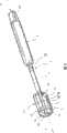
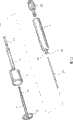
图1是根据本发明的第一种实施方式的外科组织夹具的远侧横向等轴测图;Figure 1 is a distal transverse isometric view of a surgical tissue clamp according to a first embodiment of the present invention;
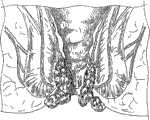
图2是图1的外科组织夹具经肛门适用于患者的近侧视图;Fig. 2 is a proximal view of the surgical tissue clamp of Fig. 1 being applied to a patient through the anus;
图3至图6示出了使用图1中的组织夹具执行的痔疮治疗的步骤;Figures 3 to 6 illustrate the steps of hemorrhoid treatment performed using the tissue clamp in Figure 1;
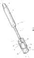
图7是根据本发明的第二种实施方式的外科组织夹具处于打开构型的远侧横向等轴测图;7 is a distal transverse isometric view of a surgical tissue clamp in an open configuration according to a second embodiment of the present invention;
图8是图7中的外科组织夹具处于闭合构型的远侧横向等轴测图;Figure 8 is a distal transverse isometric view of the surgical tissue clamp of Figure 7 in a closed configuration;
图9是图7中的细节的放大等轴测图;Figure 9 is an enlarged isometric view of the detail in Figure 7;
图10是可以与根据本发明的外科组织夹具一起使用的肛门扩张器的等轴测图;Figure 10 is an isometric view of an anal dilator that may be used with surgical tissue clamps according to the present invention;
图11是图7中的外科组织夹具的分解图;Figure 11 is an exploded view of the surgical tissue clamp in Figure 7;
图12是图7中的外科组织夹具的纵向剖视图;Figure 12 is a longitudinal sectional view of the surgical tissue clamp in Figure 7;
图13是图12中的细节的放大图;Figure 13 is an enlarged view of a detail in Figure 12;
图14是根据本发明的第三种实施方式的外科组织夹具的远侧横向等轴测图;Figure 14 is a distal transverse isometric view of a surgical tissue clamp according to a third embodiment of the present invention;
图15是根据本发明的第四种实施方式的外科组织夹具的远侧横向等轴测图;Figure 15 is a distal transverse isometric view of a surgical tissue clamp according to a fourth embodiment of the present invention;
图16是与图15相同的视图,但部分地移去了手柄外壳;Figure 16 is the same view as Figure 15, but with the handle housing partially removed;
图17是图15中的外科组织夹具的近侧视图。17 is a proximal view of the surgical tissue clamp of FIG. 15 .
具体实施方式Detailed ways
参照附图,图1是根据第一种实施方式的外科组织夹具1的总体等轴测图。组织夹具1包括在其远端区域中的夹头2和在其近端区域中的手柄3。手柄3和夹头2通过直的刚性插入轴4连接,该插入轴4适于通过手动操作保持在患者体外的手柄3将夹头2经肛门插入并定位。Referring to the drawings, Fig. 1 is a general isometric view of a
夹头2包括近侧钳口5和远侧钳口6,近侧钳口5刚性地连接到空心的管状插入轴4的远端,远侧钳口6连接到拉杆7的远端,拉杆7的近端滑动地容纳在插入轴4内,从而钳口可以相对于彼此移动并相互协作用于以相对于夹头2的纵向轴线X基本径向的定向夹紧脱垂的组织。组织夹具1还包括操作地与近侧钳口5和远侧钳口6以及触发杆9连接的致动装置8(在图1中被隐藏),触发杆9设置在手柄3处,使得触发杆9的手动致动引起钳口5、6靠近并由此夹紧脱垂的组织10(图5)。致动装置8还适于在触发杆不再运动或保持时将钳口锁定在它们的相互位置,以将钳口自动地保持在它们的组织夹紧构型。根据一种有利实施方式,致动装置被构造成允许钳口彼此分离(例如,响应于触发杆的向后运动)以释放夹紧的组织,但是在切除的组织体积可以在还被夹紧时就直接与夹头2一起除去的情况下,该特征不是不可缺少的。The
未示出的致动装置包括例如小齿轮和齿条,其适于将触发杆9的旋转运动转换成拉杆7和外部的管状插入轴4之间的相对移动,以产生钳口5、6的上述靠近。Actuating means not shown include, for example, a pinion and a rack gear, which are adapted to convert the rotational movement of the
为了更好地观察和接近待处理的组织,夹头2、特别是近侧钳口5限定三个近侧接近孔11,它们设置成允许与三个主要的内痔脉管相关的黏膜组织通过并接近该黏膜组织。如图中可以看出的,插入轴4的直径较小,优选小于夹头2的直径的一半甚至三分之一,以容易地经肛门观察或近侧接近孔11或者在该接近不受插入轴4妨碍的情况下通过另外的器械来近侧地接近。For better visualization and access to the tissue to be treated, the
近侧钳口5包括确定弯曲的组织夹紧线的细长的(slender)近侧圆形夹紧环12或者环部分。近侧夹紧环12通过近侧空间框架、特别是通过以120°角距离设置的三个细长的径向辐条13连接到插入轴,径向辐条13与近侧夹紧环12一起限定上述的接近孔11。辐条13相对于纵向轴线X倾斜,从而近侧空间框架在纵向截面上限定三角形,该三角形的远侧基部在环12处,近侧顶点在插入轴4的端部处。这使外科夹具确保严格且仅仅沿着相对于近侧空间框架13和插入轴4向远侧突出的夹紧环12的良好限定的夹紧线。辐条13的圆周厚度远小于限定在其间的近侧接近孔11的圆周长度、优选小于限定在其间的近侧接近孔11的圆周长度的三分之一或者四分之一。The
远侧钳口6包括与近侧环12或环部分互补的远侧圆形夹紧环14或环部分,该远侧圆形夹紧环14或环部分通过远侧空间框架、特别是通过以120°的角距离设置的三个细长的径向辐条15连接到由插入轴4接收的拉杆7上。The
为了确保良好限定的和精确的夹紧线,远侧辐条15倾斜,使得远侧夹紧环14相对于远侧空间框架向近侧突出。In order to ensure a well-defined and precise clamping line, the distal spokes 15 are inclined such that the
图2是适用于肛门黏膜环的外科组织夹具1的近端视图。本领域的技术人员从该图可以认识到,可以向保持在钳口中的脱垂组织10和从钳口径向向外并邻近钳口的组织10’环提供相当良好的直接可视性和接近,对于组织固定和除去脱垂组织的多余体积的执行来说,组织10和组织10’是感兴趣的主要区域。如从图2及随后的附图3至5可以看出的,根据本发明的外科组织夹具1可以在放置已知的肛门扩张器16(图10)之后插入,并且待处理的组织10’的环形区域暴露在夹紧环12和肛门扩张器16之间并由它们限定。Figure 2 is a proximal view of the
图7和图8分别示出了外科组织夹具1的第二种实施方式处于打开的钳口构型和闭合的钳口构型的视图,其中,相同的附图标记表示相同的部件。7 and 8 show views of the second embodiment of the
根据该实施方式,近侧空间框架包括大致U型的框架17,该框架17具有两个纵向的基本平行相对的腿部18和近侧基部辐条19,该腿部18的远侧连接到近侧夹紧环12,近侧基部辐条19将腿部18连接到插入轴4,从而由近侧环12和近侧空间框架17限定的接近孔11近侧和横向(径向)地暴露夹紧的组织10、10’。According to this embodiment, the proximal space frame comprises a generally
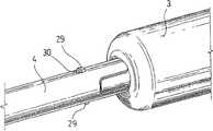
远侧空间框架包括将远侧夹紧环14连接到拉杆7的两个相对的径向辐条20。还是在该实施方式中,夹紧环12、14相对于它们的空间框架突出以限定不受干扰的夹紧线。在图11至13中详细示出的致动装置8也可以在根据第一种实施方式中的组织夹具中实施,该致动装置包括:相对于近侧钳口5可旋转但不可平移地锁定的起重螺杆21,拉杆7的与起重螺杆21啮合的螺纹连接部分22,和安装在手柄3上并且被连接以与起重螺杆21一起旋转的旋钮23,旋钮23的旋转引起起重螺杆21拧到拉杆7(拉杆7受到针对旋转的束缚而不能与起重螺杆一起旋转)上,由此使钳口5、6靠近或分离。The distal space frame comprises two opposing
起重螺杆21优选容纳在插入轴4内并包括带有两个环形凸缘24的回旋主体(相对于插入轴4的纵向轴线)的外部形状,环形凸缘24与插入轴的相应内部环形凹槽25接合,以实现上述可旋转但轴向锁定的支撑。起重螺杆21限定远侧开放的内螺纹孔28和近侧支座26,内螺纹孔28适于接收拉杆7的外螺纹的近侧连接部分22,近侧支座26优选为多边形的并用于可拆卸地接合具有互补形状的旋转杆27的远端,从而起重螺杆21能够可扭转地连接到旋转杆27且可扭转地从旋转杆27脱离。旋转杆27从起重螺杆21向近侧延伸通过手柄3,且旋转杆27的近端与设置在手柄3的近端的旋钮23连接以便优选与纵向的器械轴线X共轴地旋转。The jacking
手柄3的远端形成可拆卸连接部分,该可拆卸连接部分带有两个相对的弹性支撑的卡扣齿29,该卡扣齿29被构造成可拆卸地接合形成在起重螺杆21的近侧的插入轴4的管状壁中的相应凹槽30。以此方式,在脱垂的组织被器械夹紧之后,手柄3和,可能地,插入轴4的近侧部分能够与夹头2脱离,由此将旋转杆27的远端与起重螺杆21拆开,同时至少容纳起重螺杆21的插入轴的远侧部分和拉杆7仍然与夹头2连接。如上面已经解释的,除去手柄的可能性在痔疮切除术或痔疮修补术中的操作过程中提供了对脱垂组织的更好的视觉观察和器械接近。当然,尽管已经结合第二种实施方式对手柄拆卸特征进行了详细的描述,但本领域的技术人员清楚的是,该特征也可以实施在本发明的其它实施方式中。The distal end of the
图14示出了外科组织夹具1的第三种实施方式,其中,相同的附图标记表示相同的部件。根据该实施方式,近侧钳口5和远侧钳口6包括分别通过U形的近侧空间框架17和U形或者四边形的远侧空间框架31连接到插入轴4和拉杆7的细长的半圆形近侧和远侧夹紧环部分12、14。近侧空间框架的近侧纵向腿部18和远侧空间框架31的远侧纵向腿部32被设置成非常靠近彼此,优选部分重叠,使得由近侧空间框架17限定的近侧接近孔11不受远侧空间框架的阻碍。Fig. 14 shows a third embodiment of the
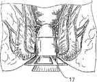
图15至17示出了本发明的第四种实施方式,根据该实施方式,外科组织夹具在内部限定适于使器械、特别是镜通过到达夹头2的纵向镜通道33。镜通道33基本上沿组织夹具1的纵向轴线X延伸并包括形成在手柄3中的近侧入口34和形成在插入轴4中的远侧出口35,远侧出口35位于近侧和远侧钳口5、6的近侧并直接面向或者穿过近侧接近孔11。FIGS. 15 to 17 show a fourth embodiment of the invention, according to which the surgical tissue clamp internally defines a
为了方便地实现镜通道33,手柄3和致动装置8都由在内部限定镜通道33的空心管状构件构成。具体参照图16,拉杆7体现为接收在限定插入轴4的两个相对的柱面部分36之间的空心管状构件。空心拉杆7的近端具有外螺纹并与直接形成在空心管状旋钮23的内部处的相应内螺纹接合,空心管状旋钮23体现了手动操作构件和起重螺杆构件。尽管在图18和19所示的示例性实施方式中,手柄不能从插入轴拆卸,但可拆卸的连接也可以有利地应用到该实施方式。In order to facilitate the realization of the
参照图3至6,通过将肛门扩张器插入到肛管已提供接近手术部位的通道来有利地执行痔疮切除术或者痔疮修补术。然后,穿过肛门扩张器将外科组织夹具1插入到肛管中,将脱垂的组织牵拉到近侧和远侧钳口之间,并且如果需要将脱垂的组织牵拉通过器械的近侧接近孔。为此,可以向脱垂的组织适用荷包缝线,并将缝线的近端牵拉穿过近侧接近孔,或者替代地,可以适用其它合适的抓取和牵拉器械,例如外科抓取器、止血钳等将组织放置到夹具1的钳口之间,同时钳口“内部”的脱垂组织通过近侧接近孔可见。在待夹紧的组织正确定位后,手动地运动旋钮23或者触发杆9使其接近钳口5、6并沿着精确的弯曲夹紧线或者环形夹紧线夹紧组织,并紧固组织用于余下的过程,该过程优选涉及通过外科医生可用的最适当的过程进行的组织固定和多余组织体积去除。应当理解,具体过程的适当性可取决于外科医生的具体技能和偏好、患者的具体病理和解剖情况以及医疗装置的成本(这在世界的较贫困区域中非常重要,这里的很多医院负担不起昂贵的器械)。用于固定脱垂的黏膜的医疗装置的示例性选择特别是外科缝线、外科钉、医疗粘合剂和谐波或超声装置,所有这些优选不同于和未包含在组织夹具1中。用于除去多余组织体积的外科装置的示例性选择特别是手术刀或者解剖刀、剪、谐波或者超声装置和射频装置,所有这些优选不同于和未包含在组织夹具1中。如本领域的技术人员能够立刻认识到的,上面描述的方法和装置对现有技术的“一包全”(所有部件在一个装置中)的方法提供了非常多样且成本经济的替代选择。Referring to Figures 3 to 6, hemorrhoidectomy or hemorrhoid repair is advantageously performed by inserting an anal dilator into the anal canal to provide access to the surgical site. The
尽管通过对若干实施方式的描述对本发明进行了说明,且所示出的实施方式已经描述的相当详细,但不是意在将后附的权利要求书的范围限定或者以任何方式限制到这样的细节。本领域的技术人员能够想到其它优点和变形。While the invention has been illustrated by the description of several embodiments, and the illustrated embodiments have been described in considerable detail, it is not intended that the scope of the appended claims be limited or in any way limited to such details. . Other advantages and modifications will occur to those skilled in the art.
Claims (12)
Applications Claiming Priority (3)
| Application Number | Priority Date | Filing Date | Title |
|---|---|---|---|
| EP06024996AEP1929965B1 (en) | 2006-12-04 | 2006-12-04 | A tissue clamp for transanal hemorrhoidopexy or hemorrhoidectomy |
| EP06024996.8 | 2006-12-04 | ||
| PCT/EP2007/061125WO2008068108A2 (en) | 2006-12-04 | 2007-10-18 | A tissue clamp for transanal hemorrhoidopexy or hemorrhoidectomy |
Publications (2)
| Publication Number | Publication Date |
|---|---|
| CN101547654A CN101547654A (en) | 2009-09-30 |
| CN101547654Btrue CN101547654B (en) | 2012-04-18 |
Family
ID=38001914
Family Applications (1)
| Application Number | Title | Priority Date | Filing Date |
|---|---|---|---|
| CN200780044748XAExpired - Fee RelatedCN101547654B (en) | 2006-12-04 | 2007-10-18 | Tissue Clips for Transanal Hemorrhoidoplasty or Hemorrhoidectomy |
Country Status (9)
| Country | Link |
|---|---|
| EP (1) | EP1929965B1 (en) |
| JP (1) | JP5203383B2 (en) |
| CN (1) | CN101547654B (en) |
| AT (1) | ATE456329T1 (en) |
| BR (1) | BRPI0719711B8 (en) |
| CA (1) | CA2670865C (en) |
| DE (1) | DE602006012069D1 (en) |
| RU (1) | RU2440793C2 (en) |
| WO (1) | WO2008068108A2 (en) |
Cited By (1)
| Publication number | Priority date | Publication date | Assignee | Title |
|---|---|---|---|---|
| CN106102619A (en)* | 2014-03-11 | 2016-11-09 | 美敦力阿迪安卢森堡有限公司 | With the independent conduit being radially expanded component and the device being associated, system and method |
Families Citing this family (5)
| Publication number | Priority date | Publication date | Assignee | Title |
|---|---|---|---|---|
| CN103908315B (en)* | 2012-12-29 | 2016-07-13 | 苏州天臣国际医疗科技有限公司 | Nail head assembly of a circular tubular stapler |
| US11484317B2 (en)* | 2019-07-08 | 2022-11-01 | Boston Scientific Scimed, Inc. | Multiple band ligation |
| CN114144127B (en)* | 2019-07-22 | 2024-12-17 | 波士顿科学国际有限公司 | Systems, devices, and methods for treating hemorrhoids |
| WO2021016390A1 (en) | 2019-07-24 | 2021-01-28 | Boston Scientific Scimed, Inc. | Device for treatment of hemorrhoids |
| WO2021021396A1 (en)* | 2019-07-29 | 2021-02-04 | Boston Scientific Limited | Devices for treatment of hemorrhoids |
Citations (3)
| Publication number | Priority date | Publication date | Assignee | Title |
|---|---|---|---|---|
| US5755732A (en)* | 1994-03-16 | 1998-05-26 | United States Surgical Corporation | Surgical instruments useful for endoscopic spinal procedures |
| US6142933A (en)* | 1998-11-23 | 2000-11-07 | Ethicon Endo-Surgery, Inc. | Anoscope for hemorrhoidal surgery |
| US6241140B1 (en)* | 1998-06-19 | 2001-06-05 | Scimed Life Systems, Inc. | Method and device for full-thickness resectioning of an organ |
Family Cites Families (8)
| Publication number | Priority date | Publication date | Assignee | Title |
|---|---|---|---|---|
| SU1333323A1 (en)* | 1985-12-17 | 1987-08-30 | С.А.Попов | Arrangement for pinching tissue |
| SU1584900A1 (en)* | 1987-05-25 | 1990-08-15 | Запорожский Облздравотдел | Device for internal investigation and operative treatment of diseases of rectum |
| SU1560134A1 (en)* | 1987-06-01 | 1990-04-30 | С. А. Попов | Device for application of anastomosis |
| RU2173102C2 (en)* | 1999-10-14 | 2001-09-10 | Половинкин Вадим Владимирович | Device for ablation of internal haemorrhoids and satere |
| DE10026683C2 (en)* | 2000-05-30 | 2003-07-10 | Ethicon Endo Surgery Europe | Surgical stapling device |
| JP4422027B2 (en)* | 2002-10-04 | 2010-02-24 | タイコ ヘルスケア グループ エルピー | Surgical stapling device |
| US7608073B2 (en)* | 2004-07-09 | 2009-10-27 | Tyco Healthcare Group Lp | Energy based partial circumferential hemorrhoid repair device |
| CA2579606C (en)* | 2004-09-10 | 2012-04-17 | Ethicon Endo-Surgery, Inc. | Surgical stapling instrument |
- 2006
- 2006-12-04DEDE602006012069Tpatent/DE602006012069D1/enactiveActive
- 2006-12-04EPEP06024996Apatent/EP1929965B1/enactiveActive
- 2006-12-04ATAT06024996Tpatent/ATE456329T1/ennot_activeIP Right Cessation
- 2007
- 2007-10-18BRBRPI0719711Apatent/BRPI0719711B8/ennot_activeIP Right Cessation
- 2007-10-18JPJP2009539684Apatent/JP5203383B2/ennot_activeExpired - Fee Related
- 2007-10-18RURU2009125526/14Apatent/RU2440793C2/enactive
- 2007-10-18CNCN200780044748XApatent/CN101547654B/ennot_activeExpired - Fee Related
- 2007-10-18WOPCT/EP2007/061125patent/WO2008068108A2/enactiveApplication Filing
- 2007-10-18CACA2670865Apatent/CA2670865C/enactiveActive
Patent Citations (3)
| Publication number | Priority date | Publication date | Assignee | Title |
|---|---|---|---|---|
| US5755732A (en)* | 1994-03-16 | 1998-05-26 | United States Surgical Corporation | Surgical instruments useful for endoscopic spinal procedures |
| US6241140B1 (en)* | 1998-06-19 | 2001-06-05 | Scimed Life Systems, Inc. | Method and device for full-thickness resectioning of an organ |
| US6142933A (en)* | 1998-11-23 | 2000-11-07 | Ethicon Endo-Surgery, Inc. | Anoscope for hemorrhoidal surgery |
Cited By (2)
| Publication number | Priority date | Publication date | Assignee | Title |
|---|---|---|---|---|
| CN106102619A (en)* | 2014-03-11 | 2016-11-09 | 美敦力阿迪安卢森堡有限公司 | With the independent conduit being radially expanded component and the device being associated, system and method |
| CN106102619B (en)* | 2014-03-11 | 2020-01-14 | 美敦力Af卢森堡有限责任公司 | Catheter with independent radial expansion member and associated devices, systems, and methods |
Also Published As
| Publication number | Publication date |
|---|---|
| WO2008068108A2 (en) | 2008-06-12 |
| RU2009125526A (en) | 2011-01-20 |
| ATE456329T1 (en) | 2010-02-15 |
| BRPI0719711B1 (en) | 2018-11-21 |
| WO2008068108A3 (en) | 2008-08-14 |
| BRPI0719711A2 (en) | 2013-12-24 |
| JP2010511450A (en) | 2010-04-15 |
| EP1929965B1 (en) | 2010-01-27 |
| BRPI0719711B8 (en) | 2021-06-22 |
| CN101547654A (en) | 2009-09-30 |
| CA2670865C (en) | 2015-03-24 |
| RU2440793C2 (en) | 2012-01-27 |
| CA2670865A1 (en) | 2008-06-12 |
| JP5203383B2 (en) | 2013-06-05 |
| DE602006012069D1 (en) | 2010-03-18 |
| EP1929965A1 (en) | 2008-06-11 |
Similar Documents
| Publication | Publication Date | Title |
|---|---|---|
| CA2613577C (en) | A tissue clamp for endolumenal local excision of tissue | |
| AU2011270654B2 (en) | Endoscopic suturing device, system and method | |
| JP4755983B2 (en) | Surgical stapling device with tissue tensioner | |
| JP5543092B2 (en) | Accessories for anvil delivery device | |
| CN101557764B (en) | Laparoscopic Suturing Device | |
| JP4184085B2 (en) | Surgical grasping instrument | |
| JP2007209754A (en) | Apparatus for performing trans anal resection | |
| CN101547654B (en) | Tissue Clips for Transanal Hemorrhoidoplasty or Hemorrhoidectomy | |
| JP2010082445A (en) | Method and device for performing gastrectomy and gastroplasty | |
| EP1830717A2 (en) | Surgical stapling instruments and methods for use | |
| JP2007313314A (en) | Lumen stabilizer for endoscopic mucosal resection | |
| CN104093366A (en) | Inserts and Insertion Systems for Laparoscopic Instruments | |
| US20230255633A1 (en) | Devices and methods for shortening a rectal stump during a lower anterior resection procedure | |
| RU110967U1 (en) | DEVICE GALIMOVA O.V. FOR FIXING THE GALL BLADDER | |
| US20020103498A1 (en) | Flexible endoscopic grasping and cutting device and positioning tool assembly | |
| CN213722193U (en) | Surgical suturing device | |
| CN101987026A (en) | Application method of anorectal tissue resection auxiliary appliance |
Legal Events
| Date | Code | Title | Description |
|---|---|---|---|
| C06 | Publication | ||
| PB01 | Publication | ||
| C10 | Entry into substantive examination | ||
| SE01 | Entry into force of request for substantive examination | ||
| C14 | Grant of patent or utility model | ||
| GR01 | Patent grant | ||
| CI01 | Publication of corrected invention patent application | Correction item:International Day of publication Correct:20080612 False:20080814 Number:16 Volume:28 | |
| CI03 | Correction of invention patent | Correction item:International Day of publication Correct:20080612 False:20080814 Number:16 Page:The title page Volume:28 | |
| ERR | Gazette correction | Free format text:CORRECT: INTERNATIONAL PROCLAMATION DATE; FROM: 2008.08.14 TO: 2008.06.12 | |
| CF01 | Termination of patent right due to non-payment of annual fee | Granted publication date:20120418 |