CN101543422B - System for determining the expansion direction of an expandable structure within a bone - Google Patents
System for determining the expansion direction of an expandable structure within a boneDownload PDFInfo
- Publication number
- CN101543422B CN101543422BCN2008100928626ACN200810092862ACN101543422BCN 101543422 BCN101543422 BCN 101543422BCN 2008100928626 ACN2008100928626 ACN 2008100928626ACN 200810092862 ACN200810092862 ACN 200810092862ACN 101543422 BCN101543422 BCN 101543422B
- Authority
- CN
- China
- Prior art keywords
- platform
- hollow member
- expandable structure
- bone
- insertion device
- Prior art date
- Legal status (The legal status is an assumption and is not a legal conclusion. Google has not performed a legal analysis and makes no representation as to the accuracy of the status listed.)
- Expired - Fee Related
Links
- 210000000988bone and boneAnatomy0.000titleclaimsabstractdescription110
- 238000003780insertionMethods0.000claimsabstractdescription146
- 230000037431insertionEffects0.000claimsabstractdescription146
- 239000000463materialSubstances0.000claimsabstractdescription18
- 230000004888barrier functionEffects0.000claimsabstractdescription4
- 239000011800void materialSubstances0.000claims1
- 239000000945fillerSubstances0.000abstractdescription15
- 238000000034methodMethods0.000description34
- 230000001054cortical effectEffects0.000description33
- 238000010276constructionMethods0.000description18
- 238000001356surgical procedureMethods0.000description12
- 238000005520cutting processMethods0.000description7
- 210000000056organAnatomy0.000description7
- 210000004872soft tissueAnatomy0.000description7
- 241001465754MetazoaSpecies0.000description6
- 230000001338necrotic effectEffects0.000description5
- 210000001519tissueAnatomy0.000description5
- 230000006378damageEffects0.000description4
- 238000002594fluoroscopyMethods0.000description4
- 238000004519manufacturing processMethods0.000description4
- -1polyethylenePolymers0.000description4
- 238000003466weldingMethods0.000description4
- 230000015572biosynthetic processEffects0.000description3
- 210000004204blood vesselAnatomy0.000description3
- 238000013461designMethods0.000description3
- 229910001220stainless steelInorganic materials0.000description3
- 239000010935stainless steelSubstances0.000description3
- 239000004698PolyethyleneSubstances0.000description2
- 238000013459approachMethods0.000description2
- 210000000746body regionAnatomy0.000description2
- 239000002639bone cementSubstances0.000description2
- 239000000316bone substituteSubstances0.000description2
- 238000000576coating methodMethods0.000description2
- 239000002131composite materialSubstances0.000description2
- 230000006835compressionEffects0.000description2
- 238000007906compressionMethods0.000description2
- 230000035876healingEffects0.000description2
- 238000012986modificationMethods0.000description2
- 230000004048modificationEffects0.000description2
- 239000004033plasticSubstances0.000description2
- 229920003023plasticPolymers0.000description2
- 229920000573polyethylenePolymers0.000description2
- 239000004814polyurethaneSubstances0.000description2
- 229920002635polyurethanePolymers0.000description2
- 230000008439repair processEffects0.000description2
- 238000005728strengtheningMethods0.000description2
- 229920000106Liquid crystal polymerPolymers0.000description1
- 239000004977Liquid-crystal polymers (LCPs)Substances0.000description1
- VVQNEPGJFQJSBK-UHFFFAOYSA-NMethyl methacrylateChemical compoundCOC(=O)C(C)=CVVQNEPGJFQJSBK-UHFFFAOYSA-N0.000description1
- 239000004677NylonSubstances0.000description1
- BPQQTUXANYXVAA-UHFFFAOYSA-NOrthosilicateChemical compound[O-][Si]([O-])([O-])[O-]BPQQTUXANYXVAA-UHFFFAOYSA-N0.000description1
- 229920005372Plexiglas®Polymers0.000description1
- 239000004743PolypropyleneSubstances0.000description1
- 239000004809TeflonSubstances0.000description1
- 229920006362Teflon®Polymers0.000description1
- 208000027418Wounds and injuryDiseases0.000description1
- 230000009471actionEffects0.000description1
- 238000002399angioplastyMethods0.000description1
- 230000002924anti-infective effectEffects0.000description1
- 239000003146anticoagulant agentSubstances0.000description1
- 210000001367arteryAnatomy0.000description1
- 238000005452bendingMethods0.000description1
- 238000005219brazingMethods0.000description1
- 210000000459calcaneusAnatomy0.000description1
- 230000000747cardiac effectEffects0.000description1
- 239000000919ceramicSubstances0.000description1
- 230000008859changeEffects0.000description1
- 238000003486chemical etchingMethods0.000description1
- 239000003795chemical substances by applicationSubstances0.000description1
- 239000011248coating agentSubstances0.000description1
- 238000005336crackingMethods0.000description1
- 230000007812deficiencyEffects0.000description1
- 229910003460diamondInorganic materials0.000description1
- 239000010432diamondSubstances0.000description1
- 238000006073displacement reactionMethods0.000description1
- 238000005553drillingMethods0.000description1
- 239000003814drugSubstances0.000description1
- 229920001971elastomerPolymers0.000description1
- 238000005530etchingMethods0.000description1
- 239000012634fragmentSubstances0.000description1
- 238000000227grindingMethods0.000description1
- 239000007943implantSubstances0.000description1
- 208000014674injuryDiseases0.000description1
- 238000010329laser etchingMethods0.000description1
- 230000013011matingEffects0.000description1
- 239000012567medical materialSubstances0.000description1
- 239000007769metal materialSubstances0.000description1
- 238000000465mouldingMethods0.000description1
- 229920001778nylonPolymers0.000description1
- 230000000399orthopedic effectEffects0.000description1
- 230000037368penetrate the skinEffects0.000description1
- 230000035515penetrationEffects0.000description1
- 229920003229poly(methyl methacrylate)Polymers0.000description1
- 229920001225polyester resinPolymers0.000description1
- 239000004645polyester resinSubstances0.000description1
- 239000004926polymethyl methacrylateSubstances0.000description1
- 229920001155polypropylenePolymers0.000description1
- 230000002980postoperative effectEffects0.000description1
- 238000012545processingMethods0.000description1
- 239000005060rubberSubstances0.000description1
- 239000012748slip agentSubstances0.000description1
- 239000007787solidSubstances0.000description1
- 229910000811surgical stainless steelInorganic materials0.000description1
- 239000010966surgical stainless steelSubstances0.000description1
- 210000002303tibiaAnatomy0.000description1
- 238000003325tomographyMethods0.000description1
- 210000000689upper legAnatomy0.000description1
- 210000003462veinAnatomy0.000description1
- XLYOFNOQVPJJNP-UHFFFAOYSA-NwaterSubstancesOXLYOFNOQVPJJNP-UHFFFAOYSA-N0.000description1
Images


Classifications
- A—HUMAN NECESSITIES
- A61—MEDICAL OR VETERINARY SCIENCE; HYGIENE
- A61B—DIAGNOSIS; SURGERY; IDENTIFICATION
- A61B17/00—Surgical instruments, devices or methods
- A61B17/56—Surgical instruments or methods for treatment of bones or joints; Devices specially adapted therefor
- A61B17/58—Surgical instruments or methods for treatment of bones or joints; Devices specially adapted therefor for osteosynthesis, e.g. bone plates, screws or setting implements
- A61B17/88—Osteosynthesis instruments; Methods or means for implanting or extracting internal or external fixation devices
- A61B17/885—Tools for expanding or compacting bones or discs or cavities therein
- A61B17/8852—Tools for expanding or compacting bones or discs or cavities therein capable of being assembled or enlarged, or changing shape, inside the bone or disc
- A61B17/8858—Tools for expanding or compacting bones or discs or cavities therein capable of being assembled or enlarged, or changing shape, inside the bone or disc laterally or radially expansible
- A—HUMAN NECESSITIES
- A61—MEDICAL OR VETERINARY SCIENCE; HYGIENE
- A61B—DIAGNOSIS; SURGERY; IDENTIFICATION
- A61B17/00—Surgical instruments, devices or methods
- A61B17/56—Surgical instruments or methods for treatment of bones or joints; Devices specially adapted therefor
- A61B17/58—Surgical instruments or methods for treatment of bones or joints; Devices specially adapted therefor for osteosynthesis, e.g. bone plates, screws or setting implements
- A—HUMAN NECESSITIES
- A61—MEDICAL OR VETERINARY SCIENCE; HYGIENE
- A61B—DIAGNOSIS; SURGERY; IDENTIFICATION
- A61B17/00—Surgical instruments, devices or methods
- A61B17/34—Trocars; Puncturing needles
- A61B17/3417—Details of tips or shafts, e.g. grooves, expandable, bendable; Multiple coaxial sliding cannulas, e.g. for dilating
- A61B17/3421—Cannulas
- A—HUMAN NECESSITIES
- A61—MEDICAL OR VETERINARY SCIENCE; HYGIENE
- A61B—DIAGNOSIS; SURGERY; IDENTIFICATION
- A61B17/00—Surgical instruments, devices or methods
- A61B17/56—Surgical instruments or methods for treatment of bones or joints; Devices specially adapted therefor
- A61B17/58—Surgical instruments or methods for treatment of bones or joints; Devices specially adapted therefor for osteosynthesis, e.g. bone plates, screws or setting implements
- A61B17/68—Internal fixation devices, including fasteners and spinal fixators, even if a part thereof projects from the skin
- A—HUMAN NECESSITIES
- A61—MEDICAL OR VETERINARY SCIENCE; HYGIENE
- A61B—DIAGNOSIS; SURGERY; IDENTIFICATION
- A61B17/00—Surgical instruments, devices or methods
- A61B17/56—Surgical instruments or methods for treatment of bones or joints; Devices specially adapted therefor
- A61B17/58—Surgical instruments or methods for treatment of bones or joints; Devices specially adapted therefor for osteosynthesis, e.g. bone plates, screws or setting implements
- A61B17/88—Osteosynthesis instruments; Methods or means for implanting or extracting internal or external fixation devices
- A61B17/885—Tools for expanding or compacting bones or discs or cavities therein
- A61B17/8852—Tools for expanding or compacting bones or discs or cavities therein capable of being assembled or enlarged, or changing shape, inside the bone or disc
- A61B17/8855—Tools for expanding or compacting bones or discs or cavities therein capable of being assembled or enlarged, or changing shape, inside the bone or disc inflatable, e.g. kyphoplasty balloons
- A—HUMAN NECESSITIES
- A61—MEDICAL OR VETERINARY SCIENCE; HYGIENE
- A61B—DIAGNOSIS; SURGERY; IDENTIFICATION
- A61B17/00—Surgical instruments, devices or methods
- A61B17/56—Surgical instruments or methods for treatment of bones or joints; Devices specially adapted therefor
- A61B17/58—Surgical instruments or methods for treatment of bones or joints; Devices specially adapted therefor for osteosynthesis, e.g. bone plates, screws or setting implements
- A61B17/88—Osteosynthesis instruments; Methods or means for implanting or extracting internal or external fixation devices
- A61B17/8866—Osteosynthesis instruments; Methods or means for implanting or extracting internal or external fixation devices for gripping or pushing bones, e.g. approximators
- A—HUMAN NECESSITIES
- A61—MEDICAL OR VETERINARY SCIENCE; HYGIENE
- A61F—FILTERS IMPLANTABLE INTO BLOOD VESSELS; PROSTHESES; DEVICES PROVIDING PATENCY TO, OR PREVENTING COLLAPSING OF, TUBULAR STRUCTURES OF THE BODY, e.g. STENTS; ORTHOPAEDIC, NURSING OR CONTRACEPTIVE DEVICES; FOMENTATION; TREATMENT OR PROTECTION OF EYES OR EARS; BANDAGES, DRESSINGS OR ABSORBENT PADS; FIRST-AID KITS
- A61F2/00—Filters implantable into blood vessels; Prostheses, i.e. artificial substitutes or replacements for parts of the body; Appliances for connecting them with the body; Devices providing patency to, or preventing collapsing of, tubular structures of the body, e.g. stents
- A61F2/02—Prostheses implantable into the body
- A61F2/30—Joints
- A61F2/44—Joints for the spine, e.g. vertebrae, spinal discs
- A61F2/441—Joints for the spine, e.g. vertebrae, spinal discs made of inflatable pockets or chambers filled with fluid, e.g. with hydrogel
- A—HUMAN NECESSITIES
- A61—MEDICAL OR VETERINARY SCIENCE; HYGIENE
- A61F—FILTERS IMPLANTABLE INTO BLOOD VESSELS; PROSTHESES; DEVICES PROVIDING PATENCY TO, OR PREVENTING COLLAPSING OF, TUBULAR STRUCTURES OF THE BODY, e.g. STENTS; ORTHOPAEDIC, NURSING OR CONTRACEPTIVE DEVICES; FOMENTATION; TREATMENT OR PROTECTION OF EYES OR EARS; BANDAGES, DRESSINGS OR ABSORBENT PADS; FIRST-AID KITS
- A61F2/00—Filters implantable into blood vessels; Prostheses, i.e. artificial substitutes or replacements for parts of the body; Appliances for connecting them with the body; Devices providing patency to, or preventing collapsing of, tubular structures of the body, e.g. stents
- A61F2/02—Prostheses implantable into the body
- A61F2/30—Joints
- A61F2/46—Special tools for implanting artificial joints
- A61F2/4601—Special tools for implanting artificial joints for introducing bone substitute, for implanting bone graft implants or for compacting them in the bone cavity
- A—HUMAN NECESSITIES
- A61—MEDICAL OR VETERINARY SCIENCE; HYGIENE
- A61F—FILTERS IMPLANTABLE INTO BLOOD VESSELS; PROSTHESES; DEVICES PROVIDING PATENCY TO, OR PREVENTING COLLAPSING OF, TUBULAR STRUCTURES OF THE BODY, e.g. STENTS; ORTHOPAEDIC, NURSING OR CONTRACEPTIVE DEVICES; FOMENTATION; TREATMENT OR PROTECTION OF EYES OR EARS; BANDAGES, DRESSINGS OR ABSORBENT PADS; FIRST-AID KITS
- A61F2/00—Filters implantable into blood vessels; Prostheses, i.e. artificial substitutes or replacements for parts of the body; Appliances for connecting them with the body; Devices providing patency to, or preventing collapsing of, tubular structures of the body, e.g. stents
- A61F2/02—Prostheses implantable into the body
- A61F2/30—Joints
- A61F2/46—Special tools for implanting artificial joints
- A61F2/4603—Special tools for implanting artificial joints for insertion or extraction of endoprosthetic joints or of accessories thereof
- A61F2/4611—Special tools for implanting artificial joints for insertion or extraction of endoprosthetic joints or of accessories thereof of spinal prostheses
- A—HUMAN NECESSITIES
- A61—MEDICAL OR VETERINARY SCIENCE; HYGIENE
- A61B—DIAGNOSIS; SURGERY; IDENTIFICATION
- A61B17/00—Surgical instruments, devices or methods
- A61B17/56—Surgical instruments or methods for treatment of bones or joints; Devices specially adapted therefor
- A61B17/58—Surgical instruments or methods for treatment of bones or joints; Devices specially adapted therefor for osteosynthesis, e.g. bone plates, screws or setting implements
- A61B17/88—Osteosynthesis instruments; Methods or means for implanting or extracting internal or external fixation devices
- A61B17/8802—Equipment for handling bone cement or other fluid fillers
- A61B17/8805—Equipment for handling bone cement or other fluid fillers for introducing fluid filler into bone or extracting it
- A—HUMAN NECESSITIES
- A61—MEDICAL OR VETERINARY SCIENCE; HYGIENE
- A61B—DIAGNOSIS; SURGERY; IDENTIFICATION
- A61B17/00—Surgical instruments, devices or methods
- A61B17/00234—Surgical instruments, devices or methods for minimally invasive surgery
- A61B2017/00238—Type of minimally invasive operation
- A61B2017/00261—Discectomy
- A—HUMAN NECESSITIES
- A61—MEDICAL OR VETERINARY SCIENCE; HYGIENE
- A61B—DIAGNOSIS; SURGERY; IDENTIFICATION
- A61B17/00—Surgical instruments, devices or methods
- A61B2017/00535—Surgical instruments, devices or methods pneumatically or hydraulically operated
- A61B2017/00539—Surgical instruments, devices or methods pneumatically or hydraulically operated hydraulically
- A—HUMAN NECESSITIES
- A61—MEDICAL OR VETERINARY SCIENCE; HYGIENE
- A61B—DIAGNOSIS; SURGERY; IDENTIFICATION
- A61B17/00—Surgical instruments, devices or methods
- A61B17/32—Surgical cutting instruments
- A61B2017/320044—Blunt dissectors
- A61B2017/320048—Balloon dissectors
- A—HUMAN NECESSITIES
- A61—MEDICAL OR VETERINARY SCIENCE; HYGIENE
- A61B—DIAGNOSIS; SURGERY; IDENTIFICATION
- A61B17/00—Surgical instruments, devices or methods
- A61B17/32—Surgical cutting instruments
- A61B2017/320052—Guides for cutting instruments
- A—HUMAN NECESSITIES
- A61—MEDICAL OR VETERINARY SCIENCE; HYGIENE
- A61F—FILTERS IMPLANTABLE INTO BLOOD VESSELS; PROSTHESES; DEVICES PROVIDING PATENCY TO, OR PREVENTING COLLAPSING OF, TUBULAR STRUCTURES OF THE BODY, e.g. STENTS; ORTHOPAEDIC, NURSING OR CONTRACEPTIVE DEVICES; FOMENTATION; TREATMENT OR PROTECTION OF EYES OR EARS; BANDAGES, DRESSINGS OR ABSORBENT PADS; FIRST-AID KITS
- A61F2/00—Filters implantable into blood vessels; Prostheses, i.e. artificial substitutes or replacements for parts of the body; Appliances for connecting them with the body; Devices providing patency to, or preventing collapsing of, tubular structures of the body, e.g. stents
- A61F2/02—Prostheses implantable into the body
- A61F2/30—Joints
- A61F2/46—Special tools for implanting artificial joints
- A61F2002/4635—Special tools for implanting artificial joints using minimally invasive surgery
- A—HUMAN NECESSITIES
- A61—MEDICAL OR VETERINARY SCIENCE; HYGIENE
- A61F—FILTERS IMPLANTABLE INTO BLOOD VESSELS; PROSTHESES; DEVICES PROVIDING PATENCY TO, OR PREVENTING COLLAPSING OF, TUBULAR STRUCTURES OF THE BODY, e.g. STENTS; ORTHOPAEDIC, NURSING OR CONTRACEPTIVE DEVICES; FOMENTATION; TREATMENT OR PROTECTION OF EYES OR EARS; BANDAGES, DRESSINGS OR ABSORBENT PADS; FIRST-AID KITS
- A61F2310/00—Prostheses classified in A61F2/28 or A61F2/30 - A61F2/44 being constructed from or coated with a particular material
- A61F2310/00005—The prosthesis being constructed from a particular material
- A61F2310/00353—Bone cement, e.g. polymethylmethacrylate or PMMA
Landscapes
- Health & Medical Sciences (AREA)
- Orthopedic Medicine & Surgery (AREA)
- Life Sciences & Earth Sciences (AREA)
- Surgery (AREA)
- Biomedical Technology (AREA)
- Engineering & Computer Science (AREA)
- Public Health (AREA)
- Heart & Thoracic Surgery (AREA)
- Animal Behavior & Ethology (AREA)
- General Health & Medical Sciences (AREA)
- Veterinary Medicine (AREA)
- Medical Informatics (AREA)
- Molecular Biology (AREA)
- Nuclear Medicine, Radiotherapy & Molecular Imaging (AREA)
- Transplantation (AREA)
- Oral & Maxillofacial Surgery (AREA)
- Neurology (AREA)
- Cardiology (AREA)
- Vascular Medicine (AREA)
- Pathology (AREA)
- Physical Education & Sports Medicine (AREA)
- Dispersion Chemistry (AREA)
- Chemical & Material Sciences (AREA)
- Prostheses (AREA)
- Surgical Instruments (AREA)
- Control Of Metal Rolling (AREA)
Abstract
Translated fromChinese
Description
Translated fromChinese本申请是申请号为01810772.9的分案申请,原案发明名称为“插入装置及其使用方法”。This application is a divisional application with application number 01810772.9, and the title of the original invention is "inserting device and method of use thereof".
技术领域technical field
本发明涉及一种插入装置,该装置能够引导可膨胀结构朝着或者背离所希望的方向和/或动物或者人体内部区域进行膨胀。本发明进一步涉及一种插入装置,用于将可膨胀结构,例如医用气囊,插入人或动物体内,其中该装置能够在尖端膨胀。本发明也涉及一种使用所所述装置进行修复、加强和/或处理骨头碎片和/或坏死骨头的方法。The present invention relates to an insertion device capable of directing the expansion of an expandable structure toward or away from a desired direction and/or internal region of an animal or human body. The invention further relates to an insertion device for inserting an inflatable structure, such as a medical balloon, into a human or animal body, wherein the device is capable of inflating at the tip. The invention also relates to a method of repairing, strengthening and/or treating bone fragments and/or necrotic bone using said device.
背景技术Background technique
可膨胀结构,例如气囊解剖器和导管,在各种外科手术中都有使用,并且用于医术中的各种康复目的。在血管成形术中,通常将气囊导管插入静脉和动脉,以扩张血管,更普通的是在血管中进行膨胀和/或清除阻塞物(例如,移除堵塞血管的阻塞物,这些可能会导致心脏病发作或者中风)。其它类型的外科用气囊用于辅助外科医生在外科手术中接近特殊器官,通常用来代替以前的注气法技术。这种气囊通常在压缩状态下通过插入装置插入体内,放置在某一器官下,插入装置包括插管、导管、或者其它类似的装置。气囊然后膨胀起来,将所希望的器官托起来,并与周围的器官和组织分开,以便在进行外科手术时更容易接近所希望的器官的侧面。气囊也可以放置并膨胀以托起其它器官和组织,使得需要进行手术的器官暴露在下方。Inflatable structures, such as balloon dissectors and catheters, are used in various surgical procedures and for various rehabilitation purposes in medicine. During angioplasty, a balloon catheter is usually inserted into veins and arteries to dilate blood vessels and, more commonly, to dilate and/or remove blockages in blood vessels (for example, to remove blockages that block blood vessels, which could lead to cardiac attack or stroke). Other types of surgical balloons are used to assist the surgeon in accessing specific organs during surgery and are often used in place of previous insufflation techniques. The balloon is usually inserted into the body in a compressed state through an insertion device and placed under a certain organ, and the insertion device includes a cannula, catheter, or other similar devices. The balloon is then inflated to hold the desired organ and separate it from surrounding organs and tissues to allow easier access to the sides of the desired organ during surgery. Balloons can also be placed and inflated to hold up other organs and tissues, exposing the organs that need surgery.
医用气囊也使用在修复和/或增强碎裂的和/或坏死的骨头的手术中。一些内科医生使用这些气囊在碎裂的和/或坏死的骨头的邻近部位形成一个工作空间,以便在骨头上安置托板、螺钉和/或其它可植入的物品。在这种手术中,通常通过切开靠近骨折部位的皮肤,插入一根插管。然后通过插管插入气囊,并在围绕骨折部位的骨头和周围组织之间进行膨胀,以形成一个工作空间。支撑板和螺钉,或者其它类似的装置,都可以通过较小的皮肤切口在骨折部位进行安装。这种手术允许外科医生安装可植入物品,而不会在皮肤上开一个很长的切口来分离并暴露骨头。Medical balloons are also used in procedures to repair and/or reinforce fractured and/or necrotic bone. Some physicians use these balloons to create a working space adjacent to the fragmented and/or necrotic bone in order to place splints, screws and/or other implantable items on the bone. In this procedure, a cannula is inserted, usually through an incision in the skin near the fracture site. A balloon is then inserted through the cannula and inflated between the bone and surrounding tissue surrounding the fracture to create a working space. Support plates and screws, or other similar devices, can be installed at the fracture site through small skin incisions. This procedure allows the surgeon to install the implant without making a long incision in the skin that separates and exposes the bone.
最近,在将要修复、加强和/或进行骨头处理的骨折和/或坏死骨头内都使用了气囊。在这些过程中,通过一根插管插入气囊,并在骨头内进行膨胀,能够压实海绵状的骨头,形成一个空洞,并且将皮层骨头移走。空洞内能够填充合适的骨头填充物,例如骨接合剂(例如,聚甲基丙烯酸甲酯-PMMA)、自身组织移植片或者同种异体移植组织,或者各种其它骨头替代物。当骨头填充物硬化后,它实际上形成了内部“造型”,允许骨头很好地愈合,同时允许骨头很快承受重量。More recently, balloons have been used in fractured and/or necrotic bones to be repaired, strengthened and/or bone manipulated. During these procedures, a balloon inserted through a cannula and inflated within the bone compacts the spongy bone, creating a cavity and dislodging the cortical bone. The cavity can be filled with a suitable bone filler, such as bone cement (eg, polymethylmethacrylate-PMMA), autograft or allograft tissue, or various other bone substitutes. When the bone filler hardens, it actually creates an internal "shape" that allows the bone to heal well while allowing the bone to bear weight very quickly.
发明内容Contents of the invention
本发明提供插入装置,可以和诸如气囊导管之类的可膨胀结构一起使用,以引导该结构靠近或者离开希望的方向的膨胀。可膨胀结构的定向膨胀可以在医生对海绵状骨头进行挤压并且在骨头上生成孔洞时为其提供有效的控制,并且可以控制皮层骨的运动。另外,可膨胀结构的受控膨胀允许医生处理孔洞的形状和尺寸,以及包含在孔洞内的填充材料团块的形状和尺寸。再者,可膨胀结构的定向膨胀允许医生在手术过程中缩小对健康海绵状骨和/或皮层骨的破坏,这进一步促进了术后骨头的痊愈。因此,这里所披露的装置和方法将允许医生优化手术完成后骨头尽可能快的承受力和/或愈合能力。The present invention provides an insertion device that can be used with an expandable structure, such as a balloon catheter, to guide expansion of the structure toward or away from a desired direction. The directed expansion of the expandable structure can provide physicians with effective control as they compress and create holes in the spongy bone and can control the movement of the cortical bone. Additionally, the controlled expansion of the expandable structure allows the physician to manipulate the shape and size of the hole, as well as the shape and size of the mass of filler material contained within the hole. Furthermore, the directed expansion of the expandable structure allows the surgeon to minimize damage to healthy spongy and/or cortical bone during surgery, which further promotes postoperative bone healing. Accordingly, the devices and methods disclosed herein will allow the physician to optimize the ability of the bone to bear force and/or heal as quickly as possible after surgery is complete.
典型情况下,诸如气囊导管和解剖器之类的可膨胀结构形成球形或者椭球形,而且通常完全向外膨胀。希望这些气囊具有相当小的外形,这样可以通过一根插管将其装入。一旦通过插管插入手术位置,通常这些气囊将绕插管或者其它插入装置的轴线对称地膨胀。然而,正如在作为参考并入此处的5,972,015号美国专利中描述的一样,气囊绕插管轴对称膨胀在某些情况下可能不是所希望的。考虑到这些情况,已经提出各种可选的气囊设计和膨胀约束配置,例如5,972,015号美国专利中描述的那些。Typically, expandable structures such as balloon catheters and dissectors form a spherical or ellipsoidal shape and are often fully outwardly expanded. It is desirable that these balloons have a relatively small profile so that they can be inserted through a cannula. Once inserted into the surgical site by the cannula, typically these balloons will inflate symmetrically about the axis of the cannula or other insertion device. However, as described in US Patent No. 5,972,015, which is incorporated herein by reference, symmetrical inflation of the balloon about the cannula axis may not be desirable in certain circumstances. With these circumstances in mind, various alternative airbag designs and inflation restriction configurations have been proposed, such as those described in US Patent No. 5,972,015.
这里,接合所披露的方法和装置,进一步披露本发明允许医生使用的多种可膨胀结构。由于插管或者其它插入装置实质上是用来引导可膨胀结构的膨胀方向,因此无需将膨胀约束并入可膨胀结构本身。另外,如果插入装置包括不透射线的材料,手术中在X射线的透视下,装置本身的方向是可以看到的,这允许医生在整个手术过程中,使用视觉检查结构的膨胀方向。当然,应当理解本发明的装置和方法,也能和并入各种膨胀约束配置的可膨胀结构结合在一起使用。Here, in conjunction with the disclosed methods and devices, further disclosure is made of a variety of expandable structures that the present invention allows physicians to use. Since the cannula or other insertion device is essentially used to guide the direction of expansion of the expandable structure, there is no need to incorporate expansion constraints into the expandable structure itself. Additionally, if the insertion device includes a radiopaque material, the orientation of the device itself can be seen intraoperatively under X-ray fluoroscopy, which allows the physician to visually check the direction of expansion of the structure throughout the procedure. Of course, it should be understood that the devices and methods of the present invention can also be used in conjunction with expandable structures incorporating various expansion constraining configurations.
在本发明通常的结构中,插入装置包括一个中空的部件,优选结构中为圆柱形,具有一个远端和一个近端,其中远端为插入装置的尖端或者插入点。中空部件的远端优选地包括一个平台,用来在一个或多个方向上约束可膨胀结构的膨胀,但是允许可膨胀结构在不受约束的方向上膨胀。其结果是,中空部件的平台作为一个支撑或者基座,可膨胀结构膨胀时压在它上面。按照需要,平台的支撑作用促使可膨胀结构膨胀离开平台,允许医生重新确定膨胀朝向或者背离希望的区域。In the general configuration of the invention, the insertion device comprises a hollow member, preferably cylindrical in configuration, having a distal end and a proximal end, wherein the distal end is the tip or insertion point of the insertion device. The distal end of the hollow member preferably includes a platform for constraining expansion of the expandable structure in one or more directions, but allowing expansion of the expandable structure in an unconstrained direction. As a result, the platform of the hollow part acts as a support or base upon which the expandable structure presses as it expands. The support action of the platform causes the expandable structure to expand away from the platform as desired, allowing the physician to reorient the expansion toward or away from the desired area.
在另一种通用结构中,平台包括平台或膨胀导向器,导向器通过插入装置的中空部件插入,按照需要导向器经过中空部件的尖端向远处扩展,进入骨头内部。按照需要导向器作为支撑或者基座,可膨胀结构压在它上面进行膨胀,它能促使可膨胀结构膨胀并离开导向器。由于导向器的这种结构经过中空部件,并且开始时无需刺入软组织和/或较硬的皮层骨,导向器的设计可以进行优化,以提供对可膨胀结构的最大支撑。In another general configuration, the platform includes a platform or expansion guide, the guide is inserted through the hollow member of the insertion device, and the guide expands distally through the tip of the hollow member into the interior of the bone as desired. The guide acts as a support or base upon which the expandable structure presses to expand, as desired, which causes the expandable structure to expand and move away from the guide. Since this configuration of the guide passes through a hollow component and does not need to penetrate soft tissue and/or harder cortical bone initially, the design of the guide can be optimized to provide maximum support for the expandable structure.
在本发明的另一种通用结构中,插入装置包括一个中空的部件,具有一个远端和一个近端,其中远端为插入装置的尖端或者插入点。中空部件的远端优选地包括一个平台,用来确定可膨胀结构的一个或者多个膨胀方向。中空部件的远端进一步包括一个或者多个折痕或者折叠线,按照需要,至少平台的一部分在插入骨头后沿着折痕或者折叠线发生变形。通过沿着预定的线发生变形,平台上的锋利表面按照希望的情况移动离开可膨胀结构。另外,平台的弯曲能够极大地影响平台与可膨胀结构接触的表面面积,以及强度和平台变形阻力。可膨胀结构压缩后,平台能够通过插管退回来,按照需要插入装置的远端使平台向下弯曲,以便取出。In another general configuration of the invention, the insertion device comprises a hollow member having a distal end and a proximal end, wherein the distal end is the tip or insertion point of the insertion device. The distal end of the hollow member preferably includes a platform for defining one or more directions of expansion of the expandable structure. The distal end of the hollow member further includes one or more creases or fold lines along which at least a portion of the platform is deformed after insertion into the bone, as desired. By deforming along a predetermined line, the sharpened surface on the platform moves away from the expandable structure as desired. In addition, the bending of the platform can greatly affect the surface area of the platform in contact with the expandable structure, as well as the strength and resistance of the platform to deformation. After the expandable structure is compressed, the platform can be retracted through the cannula, and the distal end of the device inserted as needed to bend the platform downward for removal.
在本发明的另一种通用结构中,插入装置包括一种中空部件,该部件具有多个在远端圆周上相互间隔的划线,按照需要这些划线形成多个相邻的区域,朝向第一、较低轮廓方向。当插入椎骨中理想的位置后,相邻区域按照第二方向向外膨胀,相邻区域在插入装置的尖端上完全形成一个漏斗状的锥形物或者喇叭状。当希望移走可膨胀结构时,喇叭状尖端引导可膨胀结构进入插管,便于可膨胀结构进入并通过插管。如果希望的话,相邻区域可以进一步包含一个或者多个导向器或者凸缘,这些都优选地紧密连接在可膨胀结构上,沿着理想的线和/或按照理想的方式折叠和/或扭曲可膨胀结构,进一步便于通过插管取出可膨胀结构。当希望将插入装置从椎骨内移出时,将插入装置从较硬的皮层骨中抽出来,并按照希望将相邻区域向后和/或向第一、较低轮廓方向弯曲。In another general configuration of the invention, the insertion device comprises a hollow member having a plurality of score lines spaced apart from one another on the circumference of the distal end, the score lines forming a plurality of adjacent regions as required, towards the first 1. The lower profile direction. When inserted into the desired position in the vertebrae, the adjacent region expands outward in a second direction, and the adjacent region completely forms a funnel-shaped cone or trumpet shape on the tip of the insertion device. When it is desired to remove the expandable structure, the flared tip guides the expandable structure into the cannula, facilitating entry and passage of the expandable structure through the cannula. If desired, the adjacent region may further comprise one or more guides or flanges, which are preferably closely attached to the inflatable structure, and can be folded and/or twisted along a desired line and/or in a desired manner. The expandable structure further facilitates removal of the expandable structure through the cannula. When it is desired to remove the insertion device from the vertebrae, the insertion device is withdrawn from the harder cortical bone and the adjacent region is bent posteriorly and/or toward the first, lower profile as desired.
本发明进一步涉及使用所披露的装置进行修复、加强和/或进行骨头处理的骨折和/或坏死骨头的方法。按照本发明所讲述的内容制造的插入装置的一种结构,穿透一个病人椎骨的皮层骨并插入海绵状骨头内。这种插入装置的放置便于平台指引可膨胀结构向着皮层骨部分膨胀,这样它可以在希望的方向上移动。可膨胀结构靠在平台上膨胀,按照需要引起可膨胀结构完全离开平台进行膨胀,压缩海绵状骨头形成一个孔洞,并且将皮层体的目标区域移动到希望的位置。可膨胀结构被压缩后,空洞中填充恰当骨头填充材料。这种方法,允许对具有最小海绵状骨头压缩量的皮层骨进行操作,允许医生移动目标皮层骨,同时保持许多海绵状骨头为不受压缩状态。另外,这种方法允许医生使可膨胀结构施加在皮层骨上的力最大化。The present invention further relates to methods of repairing, strengthening and/or performing bone treatment of fractured and/or necrotic bone using the disclosed device. One configuration of an insertion device made in accordance with the teachings of the present invention penetrates the cortical bone of a patient's vertebra and is inserted into the spongy bone. The placement of this insertion device facilitates the platform directing the expansion of the expandable structure towards the cortical bony portion so that it can move in the desired direction. The expandable structure expands against the platform, causing the expandable structure to expand completely off the platform as needed, compressing the spongy bone to form a hole, and moving the targeted area of the cortical body to the desired location. After the expandable structure is compressed, the cavity is filled with the appropriate bone filler material. This approach, which allows manipulation of cortical bone with minimal compression of the spongy bone, allows the surgeon to move the targeted cortical bone while leaving much of the spongy bone uncompressed. Additionally, this approach allows the physician to maximize the force that the expandable structure exerts on the cortical bone.
在本发明的另一种结构中,按照本发明所讲述的内容制成的插入装置被插入一个病人椎骨的海绵状骨头内。这种插入装置的放置便于平台指引可膨胀结构向着皮层骨部分膨胀。可膨胀结构膨胀后,按照需要压缩部分或者全部目标海绵状骨头,在海绵状皮层骨上形成一个孔洞。如果希望的话,可膨胀结构压缩后,插入装置的放置应便于平台引导可膨胀结构朝着需要压缩的海绵状骨头的另一个区域膨胀,压缩部分或者全部目标海绵状骨头,为骨头内的孔洞增加尺寸和/改变形状。如果希望的话,手术中能够反复形成具有希望尺寸的孔洞。然后孔洞中填充恰当的骨头填充材料。这种方法,便于在骨头内形成大的孔洞,允许医生调整孔洞的形状/尺寸,以优化骨头在手术后的强度和/或愈合情况。同样,所披露的方法能够被用来朝着希望的位置重新定位皮层骨。允许医生按照自己的想法逐渐移动皮层骨的小的或者大的区域。In another configuration of the invention, an insertion device made in accordance with the teachings of the invention is inserted into the spongy bone of a patient's vertebrae. Placement of such an insertion device facilitates expansion of the platform directing the expandable structure toward the cortical bone portion. After the expandable structure expands, it compresses part or all of the target spongy bone as needed, forming a hole in the spongy cortical bone. If desired, after the expandable structure is compressed, the insertion device is positioned such that the platform guides the expandable structure toward another area of the spongy bone that needs to be compressed, compressing some or all of the target spongy bone, and increasing the volume of the cavity in the bone. size and/or change shape. If desired, holes of desired size can be repeatedly formed intraoperatively. The cavity is then filled with the appropriate bone filling material. This method, which facilitates the creation of large holes in the bone, allows the doctor to adjust the shape/size of the hole to optimize the strength and/or healing of the bone after surgery. Likewise, the disclosed methods can be used to reposition cortical bone toward a desired location. Allows the physician to gradually move small or large areas of cortical bone as desired.
在另一种结构中,所披露的装置和方法便于医生在插入装置开始时位置靠近目标骨头区域的皮层骨壁的情况下,能够修复、加强和/或处理目标骨头区域。由于所披露的装置和方法提供了对可膨胀结构膨胀方向的完全控制,在一些或者所有外科手术中,医生就能够定位和/或重新定位平台,以便保护附近的皮层骨免受一些或者全部可膨胀结构的作用。根据平台的方向,结构能够扩展成不同的尺寸,按照需要,最大程度地压缩海绵状骨头和/或皮层骨在每个方向上的运动。因此,无需重新定向整个插入装置以实现手术目标,按照需要,消除了在手术中出现的另外的伤害源。In another configuration, the disclosed devices and methods allow a physician to repair, strengthen, and/or treat a target bone region where insertion of the device begins with a location proximate to the cortical bone wall of the target bone region. Because the disclosed devices and methods provide complete control over the direction of expansion of the expandable structure, during some or all surgical procedures, the physician will be able to position and/or reposition the platform so as to protect the adjacent cortical bone from some or all of the expandable structure. The role of dilated structures. Depending on the orientation of the platform, the structure can expand to different sizes, as needed, to maximize the compression of spongy bone and/or cortical bone in each direction. Thus, there is no need to reorient the entire insertion device to achieve the surgical goal, eliminating an additional source of injury during surgery, as desired.
在另一种结构中,插入装置通过皮层骨插入一个病人椎骨的海绵状骨头内。插入装置中的管心针被移动,导致插入装置中空部件的远端膨胀或成为喇叭状。一种可膨胀结构通过插入装置进入椎骨,膨胀后形成一个孔洞,然后经过压缩通过插入装置移出来。当可膨胀结构通过插入装置移出来时,按照需要插入装置的喇叭状远端引导结构进入插入装置。然后孔洞内填充入恰当的骨头填充物。In another configuration, the insertion device is inserted through the cortical bone into the spongy bone of a patient's vertebrae. The stylet in the insertion device is moved causing the distal end of the hollow member of the insertion device to expand or flare. An expandable structure is inserted into the vertebrae through an insertion device, expands to create a hole, and is then compressed and removed through the insertion device. As the expandable structure is removed through the insertion device, the flared distal guide structure of the insertion device enters the insertion device as desired. The cavity is then filled with the appropriate bone filler.
本发明的其它目标、优点和结构将在随后的描述中部分阐明,其中一部分通过这些描述将变得非常明白,或者可以从本发明的实践中弄清楚。Other objects, advantages and structures of the invention will be set forth in the ensuing description, and some of them will be obvious from the description, or can be learned from the practice of the invention.
附图说明Description of drawings
图1是椎体的冠状视图,显示插入椎体内的插管,具有在椎体内膨胀的球形可膨胀结构;Figure 1 is a coronal view of a vertebral body showing a cannula inserted into the vertebral body, with a spherical expandable structure expanded within the vertebral body;
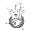
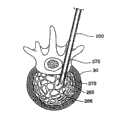
图2是椎体的冠状视图,显示按照本发明所讲述的内容制造的插入装置的一种结构,该装置已经插入椎体内,并且可膨胀结构已经在椎体内膨胀;Figure 2 is a coronal view of a vertebral body showing a configuration of an insertion device made according to the teachings of the present invention, the device having been inserted into the vertebral body and the expandable structure having been expanded within the vertebral body;
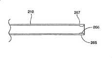
图3是按照本发明所讲述的内容制造的插入装置的另一种结构的侧视图,其中中空部件的远端在其圆周上包括一个或多个纵向划线;Figure 3 is a side view of another configuration of an insertion device made in accordance with the teachings of the present invention, wherein the distal end of the hollow member includes one or more longitudinal score lines on its circumference;
图4是图3中插入装置的横截面侧视图,显示在较低轮廓方向上的相邻区域;Figure 4 is a cross-sectional side view of the insertion device of Figure 3, showing adjacent regions in the direction of the lower profile;
图5是图3中所示插入装置的侧视图,显示处于展开或者喇叭状位置的相邻区域;Figure 5 is a side view of the insertion device shown in Figure 3, showing the adjacent region in the deployed or flared position;
图6是图3中插入装置的横截面侧视图,具有位于装置中空部件内的管心针;Figure 6 is a cross-sectional side view of the insertion device of Figure 3, with the stylet positioned within the hollow member of the device;
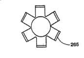
图7是图5中插入装置的一个端部;Figure 7 is an end of the insertion device in Figure 5;
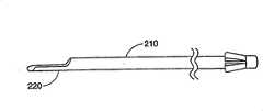
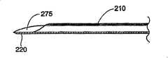
图8是按照本发明所讲述的内容制造的插入装置的另一种结构的侧视图,该装置包括从装置远端延伸出来的扩展部分或平台;Figure 8 is a side view of another configuration of an insertion device made in accordance with the teachings of the present invention, the device including an extension or platform extending from the distal end of the device;
图9是按照本发明所讲述的内容制造的插入装置的另一种结构的俯视图,显示沿着装置平台延伸的折痕线;Figure 9 is a top view of an alternate configuration of an insertion device made in accordance with the teachings of the present invention, showing crease lines extending along the platform of the device;
图10是按照本发明所讲述的内容制造的插入装置的另一种结构的侧视图,具有位于装置管腔内的管心针;Figure 10 is a side view of another configuration of an insertion device made in accordance with the teachings of the present invention, with a stylet positioned within the lumen of the device;
图11是图10中插入装置的横截面侧视图,显示较低轮廓方向上的相邻区域;Figure 11 is a cross-sectional side view of the insertion device of Figure 10, showing adjacent regions in the direction of the lower profile;
图12是图10中插入装置的侧视图,显示管心针从装置中退出后移动到展开位置的相邻区域;Fig. 12 is a side view of the insertion device of Fig. 10 showing the adjacent region moved to the deployed position after the stylet has been withdrawn from the device;
图13是按照本发明所讲述的内容制造的插入装置的另一种结构的端视图;Figure 13 is an end view of another construction of an insertion device made according to the teachings of the present invention;
图14是图13中插入装置的侧视图;Figure 14 is a side view of the insertion device in Figure 13;
图15是图13中插入装置的侧视图,具有位于装置中空部件内的管心针;Figure 15 is a side view of the insertion device of Figure 13 with the stylet positioned within the hollow member of the device;
图16是按照本发明所讲述的内容制造的插入装置的另一种结构的侧视图,具有位于装置中空部件内的管心针;Figure 16 is a side view of another configuration of an insertion device made in accordance with the teachings of the present invention, with a stylet positioned within the hollow part of the device;
图17是按照本发明所讲述的内容制造的管心针的一种结构的侧视图,用来和本发明插入装置的各种结构一起使用;Figure 17 is a side view of one configuration of a stylet made in accordance with the teachings of the present invention for use with various configurations of the insertion device of the present invention;
图18是按照本发明所讲述的内容制造的管心针的另一种结构的侧视图,用来和本发明插入装置的其他结构一起使用;Figure 18 is a side view of an alternate configuration of a stylet made in accordance with the teachings of the present invention for use with other configurations of the insertion device of the present invention;
图19是按照本发明所讲述的内容制造的插入装置和管心针的另一种结构的横截面侧视图,显示装配装置和管心针的一种方法;Figure 19 is a cross-sectional side view of another configuration of an insertion device and stylet made in accordance with the teachings of the present invention, showing one method of assembling the device and stylet;
图20是图19中显示的插入装置和管心针的横截面侧视图,显示装配中管心针完全插入装置的中空部件之内;Figure 20 is a cross-sectional side view of the insertion device and stylet shown in Figure 19, showing the assembled stylet fully inserted into the hollow member of the device;
图21是图20中插入装置和管心针的横截面侧视图,其中装置的相邻部分位于管心针周围较低轮廓方向上;Figure 21 is a cross-sectional side view of the insertion device and stylet of Figure 20 with the adjacent portion of the device in the direction of the lower profile around the stylet;
图22描绘了按照本发明所讲述的方法,病人准备接受外科手术;Figure 22 depicts the patient being prepared for surgery according to the method taught by the present invention;
图23描绘了图22中病人的切开点和下面的椎骨;Figure 23 depicts the incision point and underlying vertebrae of the patient in Figure 22;
图24是椎骨的冠状视图,显示插入装置接近椎体的后侧;Figure 24 is a coronal view of the vertebra showing the posterior side of the insertion device close to the vertebral body;
图25描绘了插入装置插入图24中的椎体;Figure 25 depicts the insertion of the insertion device into the vertebral body in Figure 24;
图26是图24中椎体的冠状视图,其中插入装置位于海绵状骨头之内;Figure 26 is a coronal view of the vertebral body in Figure 24 with the insertion device within the spongy bone;
图27是图25中的椎体的冠状视图,其中相邻区域处于展开方向;Figure 27 is a coronal view of the vertebral body in Figure 25 with adjacent regions in the deployment orientation;
图28是图27中椎体的冠状视图,其中可膨胀结构在椎体内膨胀;Figure 28 is a coronal view of the vertebral body of Figure 27 with the expandable structure expanded within the vertebral body;
图29是椎体的冠状视图,显示插入装置包括一个在椎体内的平台,和一个膨胀后离开插入装置平台的可膨胀结构;Figure 29 is a coronal view of the vertebral body showing the insertion device comprising a platform within the vertebral body and an expandable structure that leaves the insertion device platform after expansion;
图30是图29中椎体的冠状视图,其中可膨胀结构已经压缩,装置转动,可膨胀结构向着椎体的另外一个区域膨胀;Figure 30 is a coronal view of the vertebral body of Figure 29, wherein the expandable structure has been compressed, the device is rotated, and the expandable structure is expanded toward another region of the vertebral body;
图31是图29中椎体的冠状视图,其中所产生的孔洞填满了骨头填充物;Figure 31 is a coronal view of the vertebral body in Figure 29 with the resulting hole filled with bone filler;
图32是图29中椎体的冠状视图,其中使用可膨胀结构和插入装置来扩大已经部分填充了骨头填充物的第一孔洞;Figure 32 is a coronal view of the vertebral body in Figure 29, wherein the expandable structure and insertion device are used to enlarge the first hole that has been partially filled with bone filler;
图33是按照本发明所讲述的内容制造的各种结构的侧面透视图;Figure 33 is a side perspective view of various structures made according to the teachings of the present invention;
图34是按照本发明所讲述的内容制造的膨胀导向器的一种结构的侧面透视图;Figure 34 is a side perspective view of a configuration of an expansion guide made in accordance with the teachings of the present invention;
图35是图34中放入插入装置的膨胀导向器的部分侧面透视图;Figure 35 is a partial side perspective view of the expansion guide inserted into the insertion device of Figure 34;
图36是按照本发明另一种结构制造的插入装置的另一种结构的侧视图;Figure 36 is a side view of another structure of an insertion device manufactured according to another structure of the present invention;
图37是图36中插入装置沿32-32线剖分后的横截面视图;Figure 37 is a cross-sectional view of the insertion device in Figure 36 taken along line 32-32;
图38是图36中插入装置沿33-33线剖分后的横截面视图;Figure 38 is a cross-sectional view of the insertion device in Figure 36 taken along line 33-33;
图39是按照本发明另一种结构制造的插入装置的另一种结构的侧视图;Figure 39 is a side view of another structure of an insertion device manufactured according to another structure of the present invention;
图40是图39中插入装置沿35-35线剖分后的横截面视图;Figure 40 is a cross-sectional view of the insertion device in Figure 39 taken along line 35-35;
图41是图39中插入装置沿36-36线剖分后的横截面视图;Figure 41 is a cross-sectional view of the insertion device in Figure 39 taken along line 36-36;
图42是在一种制造图39中插入装置的方法中的某一步骤中,沿36-36线剖分的横截面视图;Figure 42 is a cross-sectional view taken along line 36-36 during a certain step in a method of making the insertion device of Figure 39;
图43是图42中插入装置在随后的制造步骤中的横截面视图;Figure 43 is a cross-sectional view of the insertion device of Figure 42 during a subsequent manufacturing step;
图44是图42中插入装置在随后的制造步骤中的横截面视图。Figure 44 is a cross-sectional view of the insertion device of Figure 42 at a subsequent manufacturing step.
具体实施方式Detailed ways
本发明克服了目前用于可膨胀结构例如医用气囊的插入装置的策略和设计中有关的问题和不足。特别是,本发明提供插入装置,可以和可膨胀结构一起使用,引导结构膨胀并辅助从人体或者动物体的内部区域插入或者取出可膨胀结构。适合于这种处理方法和仪器在4,969,888、5,108,404、5,827,289、5,972,015、6,048,346和6,066,154号美国专利中有详细的描述,这些专利都作为参考并入此处。The present invention overcomes problems and deficiencies associated with current strategies and designs for insertion devices for inflatable structures such as medical balloons. In particular, the present invention provides insertion devices that may be used with expandable structures to guide expansion of the structure and assist in the insertion or removal of the expandable structure from an internal region of the human or animal body. Methods and apparatus suitable for such processing are described in detail in US Patent Nos. 4,969,888, 5,108,404, 5,827,289, 5,972,015, 6,048,346 and 6,066,154, all of which are incorporated herein by reference.
图1描绘了将要使用可膨胀结构310进行手术的椎骨41。一种插入装置,例如插管或者脊椎穿刺针,延伸通过椎骨41的皮层骨69,进入海绵状骨头71。通过插入装置,可膨胀结构310进入椎骨41,按照需要在海绵状骨头内膨胀,典型情况下向外膨胀形成球形、圆柱形或者其它形式,从而形成一个孔洞。为了避免在结构310膨胀的过程中接触皮层骨69,医生将把插入装置放置在离皮层骨69足够远的地方,以便结构310具有足够的向外膨胀空间。然而,如果插入装置的位置太靠近皮层骨69,并且结构向着皮层骨69膨胀得更大(在某个方向上海绵状骨头更加疏松),或者如果中间组织严重制约插入装置的放置位置使其靠近皮层骨69,结构的膨胀和形成的洞就可能不那么理想。FIG. 1 depicts a
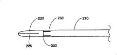
图2和8描绘了按照本发明所讲述的内容制造的插入装置的一种结构。插入装置包括一个中空部件210,它可以具有任意恰当的形状,但是优选结构为圆柱体。中空部件210具有一个远端250和一个近端255,其中远端250是一个尖端,或者是插入装置的插入点。中空部件210可以具有任意恰当的长度,以便插入装置能够经过皮肤进入所要实行手术的身体内部。在一种优选结构中,中空部件210约12厘米长。Figures 2 and 8 depict a configuration of an insertion device made in accordance with the teachings of the present invention. The insertion device comprises a
中空部件210具有外科器械所允许的适当的中心孔直径和壁厚,以便外科仪器和/或医用材料穿过,同时希望其足够坚固,以便在插入人体内部区域例如骨头过程中能够抵抗变形。在一种优选结构中,中空部件210具有直径为0.3厘米的内孔和0.05厘米的壁厚。中空部件210可以进一步由任何适于在人体或者动物体内使用的材料制成,包括但是不限于,外科用不锈钢、特氟纶、聚乙烯、聚丙烯、硅酸盐,以及液晶聚合体(如6,036,711号美国专利所述,作为参考并入此处)。在一种优选结构中,中空部件210由不锈钢制成。如果希望的话,中空部件210可以进一步涂有任何合适的医用等级涂层,包括但是不限于,防感染剂、防凝结剂、释放涂层,和/或增滑剂。The
在一种结构中,从中空部件210的远端250上突出一个延伸物或者平台220。在这种结构中,平台220包括一个从中空部件210壁上延伸出来的半圆柱形部分。当然,平台可以形成许多种不同的结构,包括一个或者多个显示在图33中的结构。在一种优选结构中,平台220由和中空部件210同样的材料制成。当然,应当理解平台220可以由不同于形成中空部件210的材料构成,和/或涂有与中空部件210的不同材料。另外,平台220可以和中空部件210一起成形,例如将中空部件210靠近远端250的一部分切去,留下一个托架的形状;或者通过各种在本工艺中已知的方式,例如焊接、粘接等,将平台220连接在中空部件210的远端250上。在一种结构中,平台220将具有足够的圆柱方向的强度,以便插入装置通过软组织和/或骨头时,不会发生屈曲或者变形。在所披露的结构中,中空部件210的远端250的部分在纵向被切断移走,剩余的半圆柱部分包括平台220。In one construction, an extension or
按照需要,膨胀前平台220将放置在靠近可膨胀结构310的地方,平台220位于可膨胀结构310和椎骨41内尚未压缩或受影响的区域之间。当结构310膨胀时,平台220将作为可膨胀结构310的支撑、基础或者阻挡层,阻止结构310在一个或多个方向上膨胀。其结果是,平台220将引起可膨胀结构310膨胀离开平台220。由于插入装置和平台220完全处于皮层骨内,当结构膨胀时,平台220将在椎骨内保持完全刚性和/或固定。这种配置允许医生确定可膨胀结构310的膨胀方向,朝向或者背离椎骨内特定区域。As desired, the
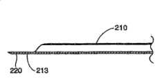
在另一种结构中,显示在图9中,平台220包括至少一个纵向折线225,优选结构中位于靠近平台中心的地方,至少平台220的一部分在结构310膨胀之前、膨胀中或者膨胀之后沿着该折线发生变形。通过使平台220按照控制的方式发生变形,这种结构便于平台进入低轮廓状态,允许平台变形形成更大的面积,以便更好地对结构的膨胀定向,然后允许平台从较低轮廓状态中恢复。因此在平台220上设置压力折线225便于平台220以受控的方式变得平直,从而为引导可膨胀结构310膨胀提供了更宽的和改进的支撑表面。使平台220变平也能够使平台220可以是锋利的边缘向外变形,因此降低了破坏或者割裂可膨胀结构310的危险。折线225可以是通过机械切割、激光蚀刻、焊接、钎接或者其它任何已知方法加工的。In another configuration, shown in FIG. 9 , the
在另一种结构中,折线225能够加强平台220,减小平台220在结构310膨胀过程中的变形。例如,平台220的圆形下侧面能够沿着平台的纵向轴卷曲或者弯曲,使得平台220变硬,并且可以抵抗此类变形。如果希望的话,卷曲(图中未显示)可以与一个或者多个折线225平行。在另一种结构中,卷曲(图中未显示)从平台220的远端250延伸约7毫米,导致平台抵抗移动和/或变形的能力大幅增加。In another configuration, fold
在另一种结构中,平台的远端包括一个或者多个锯齿或者齿状物,它们从远端向外伸出,便于平台在目标骨头区域对面的皮层骨壁上固定。这种配置,允许平台两端支撑,大幅增加了平台在可膨胀结构膨胀的过程中抵抗位移和/或变形的能力。In another configuration, the distal end of the platform includes one or more serrations or teeth extending outwardly from the distal end to facilitate fixation of the platform on the cortical bone wall opposite the target bony region. This configuration, allowing the platform to be supported at both ends, substantially increases the platform's ability to resist displacement and/or deformation during expansion of the expandable structure.
在显示在图14、15和16中的另一种结构中,平台220包括一个从中空部件210的远端250伸出的相对平坦的部分。在优选结构中,平台220能够包括一个平坦的顶部表面212和一个弯曲的外表面213,弯曲外表面213和中空部件210一起成形。尽管这种结构稍微限制了中空部件210的内孔,平台220的形状和增加的厚度极大地增加了平台220没有变形时能够承受的力。另外,这种结构时可膨胀结构上的锋利边缘的卷曲减小到最小。再者,如图16所示的平坦的较厚平台220能够形成具有锋利尖端,这样平台220能够很容易地穿过软组织和/或骨头。在另一种结构中,一个柔软的和/或易弯曲的表面(图中未显示)可以放置在可膨胀结构和/或平台之间,或者可以包括在平台或者可膨胀结构内,用来使可膨胀结构的撕裂、切开和/或其它失效形式减小到最小。In another configuration shown in FIGS. 14 , 15 and 16 ,
图34和35显示按照本发明所讲述的方法制造的插入装置和相关部件的另一种结构。在这种结构中,插入装置或者插管包括一个中空部件210,它可以具有任意恰当的形状,但是优选结构为圆柱体。中空部件210具有一个远端250和一个近端255,其中远端250是一个尖端,或者是插入装置的插入点。图34中所示的膨胀导向器400包括一个手柄装置405和一个导向轴410。按照需要导向轴410比中空部件210长,而且其尺寸可以通过中空部件210的管腔。在所披露的这种结构中,导向轴410的上表面420最好是平坦的,而导向轴的下表面415是弯曲的。如果希望的话,手柄装置405和/或导向轴410能够包括一个或者多个对齐标志407,以表示导向轴的方向和导向轴从中空部件远端250伸出来的量。另外,手柄装置可以包括机械连接器或者卡头(图中未显示),以便将膨胀导向器400固定在中空部件210上。Figures 34 and 35 show another construction of an insertion device and associated components made according to the method taught by the present invention. In this configuration, the insertion device or cannula includes a
在这种结构中,当插入装置进入目标椎骨内后,膨胀前膨胀导向器400放置在靠近可膨胀结构(图中未显示)的地方,导向轴410位于可膨胀结构和不希望进行海绵状骨头压缩的海绵状骨头区域。如果希望的话,可膨胀结构可以在膨胀导向器400通过插入装置进入之前通过插入装置进入。结构膨胀时,导向轴410将作为一个支撑、基础或者阻挡层,阻止结构310在一个或多个方向上膨胀。其结果是,导向轴410将与前述的平台220一样起作用,将引导可膨胀结构310膨胀离开导向轴410。这种配置允许医生确定可膨胀结构310的膨胀方向,朝向或者背离椎骨内特定区域。另外,由于膨胀导向器400在中空部件内的插入深度可以改变,医生能够选择希望的导向轴410伸出插入装置的长度。在另一种结构中,如果希望的话,可以使用多个平台(图中未显示)来保护多个方向。In this configuration, after the insertion device enters the target vertebra, the
由于膨胀导向器400可以在插入装置已经进入目标椎骨内以后才进入,膨胀导向器400不需要足够的圆柱方向强度来穿透软组织和骨头。这允许膨胀导向器400具有许多横截面形式,包括显示在图33中的一个或者多个形式。Since the
按照本发明所讲述的内容制造的插入装置的另一种结构中,在图3、5和7中有最好的显示,插入装置包括一个圆柱形中空部件210,它可以具有任意恰当的形状,但是优选结构为圆柱体。中空部件210具有一个远端250和一个近端255,其中远端250是一个尖端,或者是插入装置的插入点。中空部件210的远端250上有纵向刻痕,在中空部件210的圆周上形成多个划线260。多个划线260可以相互平行或者成某一角度,并且被相邻的区域265隔开。划线260可以具有适合的长度和深度,以便当在相邻区域265上施加向外的压力时,其远端250形成喇叭状(见图5和7)。In another construction of an insertion device made according to the teachings of the present invention, best shown in Figures 3, 5 and 7, the insertion device comprises a cylindrical
在一种优选结构中,划线260沿着中空部件210的纵轴延伸约0.5厘米,并且延伸通过中空部件210的内壁。可以使用本领域技术人员所知的任何技术,包括但是不限于,蚀刻、化学蚀刻和/或用硬质合金或金刚石尖端锯或高压水进行机械切割,在远端250上切割划线260。按照需要,中空部件210的远端250将包括足够数量的纵向划线260,以便远端250易于形成喇叭状。形成适合的喇叭状所需的划线260的数量取决于中空部件210的直径和壁厚,以及材料的延展性。在本发明的一种结构中,中空部件210在远端250上包括至少三条划线260。在图7中显示的另一种结构中,中空部件210在远端250上包括六条划线260。In a preferred construction, the
中空部件210的尖端形成喇叭状便于可膨胀结构例如医用气囊的插入和取出。通过使尖端形成喇叭状,中空部件210锋利的外边缘被从可膨胀结构上推开进入周围的海绵状骨头中。因此可膨胀结构与这些锋利边缘隔开,否则这些锋利边缘可以在可膨胀结构膨胀时与结构接触,可能导致结构破裂或者损坏。在抽出可膨胀结构的过程中,喇叭状尖端较大的直径将引导可膨胀结构进入较小直径的中空部件210,使得抽出可膨胀结构进入并通过中空部件210变得容易。The tip of the
如果希望的话,通过使用可膨胀结构提供希望的向外的力,可以使尖端变成喇叭状,或者可以通过机械的方式使尖端变成喇叭状。例如,在图4所示的结构中,相邻区域在其内表面上被加厚,以形成一个或者多个从每个相邻区域265向内延伸的突起266。如果希望,突起266能形成远端250圆周上的单个连续的较厚区域,连续区域由划线260打断。当工具,例如钝头封闭器、钻孔部件或者管心针275,这将在下文中描述,滑过或者压在突起266上时,相邻区域265受压向外,使中空部件210的远端250按照理想的方式形成喇叭状。If desired, the tip can be flared by using an expandable structure to provide the desired outward force, or the tip can be flared mechanically. For example, in the structure shown in FIG. 4 , the adjacent regions are thickened on their inner surfaces to form one or
本发明的插入装置可以进一步包括一个可移动的钝头封闭物或者管心针275,见图6、10、11、15和21。管心针275包括具有尖端276的远端279,尖端276可以是钝的,也可以是锋利的。如果希望,如本领域所公知的,管心针上可以安装插管(图中未显示)以放置脊椎穿刺针装置的定距索。在本发明的一种结构中,显示在图18、19和21中,按照需要,当插入装置装配好用来插入体内区域时,管心针275的尖端276将从中空部件210的远端250中延伸出来。按照需要,管心针275推动和/或在软组织或者骨头上切割出一个管道或者通道,以便将插入装置放入希望的体内区域。如果需要,管心针275可以进一步包括一个配合端(图中未显示),允许钻孔部件275在插入过程中按照本工艺中熟知的方式与插入装置配合。中空部件210与管心针275的配合能够阻止在插入病人体的过程中这些装置之间的滑动或者相对运动。优选地,管心针275按照某种方式与中空部件210配合,这种方式允许插入装置放入目标区域后,很容易地将管心针275从中空部件210移出来。The insertion device of the present invention may further include a removable blunt closure or
管心针275可以由任何合适的医用等级材料制成,优选结构中和中空部件210的材料一样。在一种优选结构中,管心针275由不锈钢制成。管心针275可以进一步具有任意适当的形状和尺寸,这允许它在中空部件210内滑动,并与之配合。在一种优选结构中,管心针275近似为和中空部件210相同的圆柱形,并且比中空部件210略长,以便当安装完毕插入时,尖端276从中空部件210的远端250伸出来;并且比中空部件210的内孔直径略小,以便管心针275能够在中空部件210内自由滑动,容易插入和抽出来。
在本发明的一种结构中,显示在图18、19、20和21中,按照需要,管心针275的远端279在靠近尖端276的位置上包括一个或多个沟槽或者麻点273。在一种优选结构中,麻点273为连续的麻点,将管心针275的远端279的圆周包围起来。管心针275在远端279处至少具有一个麻点,这非常适合于与在远端250的每个相邻区域上具有多个纵向划线260以及一个或者多个突起266的中空部件210进行配合,如图4、6和21所示。当这种插入装置装配完毕后,管心针275就能插入中空部件210中,直到远端279伸出中空部件210。然后,相邻区域265折叠或者向内卷曲,突起266延伸进入管心针275上的麻点273中,这样中空部件210的外壁在插入装置插入之前相对为一个圆柱形。一旦插入装置进入希望的体内区域,管心针275从中空部件210中拔出来,使一个或者多个突起变成喇叭状,并迫使管心针275的远端279向外移动。在另一种结构中,邻近一个或者多个突起266的套环部分267比中空部件壁的其它部分薄,这样远端250更易形成喇叭状。In one configuration of the invention, shown in FIGS. 18, 19, 20 and 21, the
在按照本发明所讲述的内容制造的插入装置的另一种结构中,显示在图10到12中,插入装置包括一个具有平台220和一个或者多个相邻区域的中空部件210,相邻区域由远端250上的多个纵向划线260分隔开。在另一种结构中,这种插入装置进一步包括管心针275,管心针具有至少一个麻点273,位于靠近尖端276的地方。管心针275可以用来在相邻区域265上的一个或者多个突起266上施加向外的压力,使远端250在靠近平台220的地方形成喇叭状。本发明的插入装置的这种优选结构允许使用者确定可膨胀结构,例如医用气囊的膨胀方向,同时使可膨胀结构的插入和取出变得容易,并且降低了损坏可膨胀结构的危险。In another construction of an insertion device made in accordance with the teachings of the present invention, shown in FIGS. are separated by a plurality of
本发明进一步提供一种方法,包括使用所披露的插入装置确定可膨胀结构膨胀方向和/或简化向人体或动物体内插入和取出可膨胀结构的方法。为了图示的目的,将描述一种疏松椎骨固定方法,即在椎骨内插入并膨胀的方法。然而,可以在人体活动物体内适当的区域使用同样的方法。The present invention further provides a method comprising using the disclosed insertion device to determine the direction of expansion of an expandable structure and/or to simplify the method of inserting and removing an expandable structure from a human or animal body. For purposes of illustration, a loose vertebral fixation method, ie, a method of insertion and expansion within a vertebra, will be described. However, the same method can be used in appropriate areas within a living body.
如图22-32所示,在本发明的一种结构中,病人10被放置在通常为U形的支架15上,这样病人的背部就可以暴露出来。X射线机、X体轴断层摄影扫描仪、核磁共振成像仪、荧光检查器或者其它适合的设备20可以放置在病人的周围,这些设备允许医生在外科手术过程中看见插入装置的插入和放置。插入装置20包括一个安装有管心针275的中空部件210,如前所述,可以通过软组织进入椎骨内,它可以通过荧光检查器进行准确的定位。按照需要,管心针和插入装置穿透椎骨30的皮层骨31,然后将管心针275移走。在插入装置的一种结构中,中空部件210包括一个或者多个由多个纵向划线265分隔的相邻区域265,按照需要,移走管心针275将导致中空部件210的远端250形成图27所示的喇叭状。As shown in Figures 22-32, in one configuration of the invention, a
一个可膨胀结构50,例如医用气囊,可以通过中空部件210插入椎骨30。可以通过适当的方式监视可膨胀结构50的放置,包括X射线透视或者实时核磁共振成像。结构膨胀后,在海绵状骨头内形成一个孔洞55和/或移动皮层骨31,然后结构压缩。在一种结构中中空部件210的远端250已经形成喇叭状,喇叭端引导结构50进入中空部件210。然后在孔洞55内填充适当的骨头填充物60。An
在本发明的另一种优选结构中,中空部件210包括一个从远端250伸出的平台220。从图29到32中可以看到。一旦中空部件210进入椎骨30,中空部件210就能旋转直到平台220遮蔽住椎骨中不希望结构50膨胀的一部分。当结构50膨胀后,平台220引起结构50膨胀离开平台220。在这种情况下,所形成的孔洞的恰当面积通常和插入装置在椎骨内的位置无关。因此,如果插入装置放置在椎骨内的位置不是形成孔洞的最佳位置,不需要扭转、弯曲、或者调整整个插入装置的位置,而只需简单地转动插入装置200直到平台面向形成孔洞的理想方向。按照需要,中空部件210的手柄或者近端部分上的标记(图中未显示)将指示医生确定平台在骨头内的方向。同样,如果希望形成较大或者不对称的孔洞,当通过结构50的膨胀形成第一孔洞后,结构50压缩,插入装置200可以转动使平台朝向另一个方向,然后相同或者不同尺寸的结构50再次膨胀,形成第二孔洞,等等,如图30所示。通过这种方式,可以形成任何希望的数量和/或尺寸的孔洞。在另一种结构中,可以插入不同形状的气囊形成不同尺寸的孔洞,或者可以使用不同形状的多个可膨胀结构来形成每个孔洞。In another preferred configuration of the present invention,
当形成希望的一个孔洞或者多个孔洞55后,可膨胀结构50可以被压缩并通过中空部件210移出来。在一种结构中,中空部件210的远端250形成喇叭状,压缩结构的移动可以更为容易,因为喇叭状尖端能够引导结构进入中空结构210。一种合适的骨头替代物,例如有机玻璃骨接合剂,两种成分的聚亚安酯,或者其它合适的骨头填充物60,注入形成的孔洞中。在一种结构中,可以首先形成第一孔洞,如果希望的话,至少部分填充骨填充物60,然后使用同样或者不同的可膨胀结构50插入同一个孔洞55并进行膨胀,因此压紧了坚硬的骨填充物和/或更多的海绵状骨头,然后孔洞55可以进一步填充相同或者不同的骨填充物60。在另一种结构中,可以先形成第一孔洞55,然后转动具有平台220的插入装置200,插入相同或者不同的可膨胀结构50以形成第二孔洞,或者扩大第一孔洞55,然后在这些孔洞中填充相同或者不同的骨填充物60。然后继续这种方法,直到形成并填充了所有希望的孔洞。After the desired hole or holes 55 are formed, the
一旦所有希望的孔洞都填充完毕以后,插入装置200可以从椎骨30中取出。然后将切口25缝合和/或用绷带缚上。
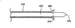
图36-38描绘了按照本发明所讲述的内容制造的插入装置600的另一种结构。插入装置600包括一个中空部件620和一个可膨胀结构710。在中空部件510的远端上提供一个手柄615,以便于操作工具和/或插入介质使可膨胀结构710膨胀。按照需要,中空部件620具有一个在内部延伸的管腔622,包括轴624和远端尖端625。轴624的远端625形成圆形或斜面,以便穿过皮层骨/海绵状骨,或者可以形成扁平状以减小穿过目标骨头区域对面的皮层壁的可能性。在轴624上加工有一个开口或者窗口700,按照需要可膨胀结构710放置在管腔内邻近窗口700的地方。当插入装置600插入目标骨头区域(图中未显示)后,可膨胀结构710膨胀(见图38、P1到P2到P3),按照需要至少可膨胀结构710的一部分将膨胀穿过窗口700,从而对海绵状骨头进行压缩,形成孔洞和/或移动皮层骨。可膨胀结构710压缩后,按照需要,大部分的可膨胀结构通过管腔622进入装置600,以便移动装置600从椎骨内退出来。如果希望的话,手柄615和/或中空部件510的近端612包括标记点(图中未显示),用来指示目标骨头区域内窗口700的方向。36-38 depict another configuration of an
可膨胀结构710可以由医用设备应用中通用的柔性材料制成,包括但是不限于,塑料、聚乙烯、聚酯树脂、橡胶、尼龙、聚亚安酯、金属或者合成材料。按照需要,轴624将包括比制造可膨胀结构710的材料更能抵抗膨胀的材料,包括但是不限于,不锈钢、陶瓷、合成材料和/或硬质塑料。在另一种结构中,轴624和可膨胀结构可以使用相同的材料,但是具有不同的厚度和/或量,从而使得可膨胀结构比轴624更易于膨胀。可膨胀结构710可以通过各种在本工艺中熟知的方式直接和轴624连接在一起,包括但是不限于,例如焊接、熔接、粘接或者类似方式。在另一种结构中,可膨胀结构可以固定在轴624的内部或者外部,或者连接在它上面。在至少另一种结构中,构成可膨胀结构710的至少一部分材料在膨胀时会发生塑性变形。The
如果希望的话,轴624的尺寸可以通过已经位于目标骨头区域内的插管或者脊椎穿刺针(图中未显示)的管腔。或者,插入装置600的这种结构可以无需相关插入装置而单独使用。在这种情况下,插入装置600将包括一个锋利的、能够刺穿椎骨的软组织和皮层骨/海绵状骨头的远端尖端625。远端尖端可以是中空的或者是实心结构,这取决于所希望的装置600的强度。同样窗口700可以或多或少围绕轴624的圆周延伸,这取决于可膨胀结构710的结构尺寸和希望的装置刺穿强度。例如,窗口在轴624上延伸约25%,装置600的刺穿强度将比窗口在轴624上延伸约75%大幅增加。如果希望的话,手柄615可以包括一个碰撞面(图中未显示),以便在把装置600放入目标骨头区域时使用矫形槌。在另一种结构中,形成孔洞后,可以将可膨胀结构从中空部件600中取出,以便通过中空部件在孔洞内放入骨头填充物。If desired, the shaft 624 may be sized to pass through the lumen of a cannula or spinal needle (not shown) already positioned within the targeted bony region. Alternatively, this configuration of
图39到41描绘了按照本发明另一种结构制造的膨胀导向器800的另一种结构。在这种结构中,平台810包括一个从中空部件820的壁向外伸出的半圆柱形区域。一个缺口825沿着平台820的纵向延伸。缺口825将用来放置键或者可膨胀结构的突起(图中未显示),按照需要用来将可膨胀结构固定在平台上。39 to 41 depict another construction of an
当可膨胀结构靠在平台上膨胀时,结构能够滑落平台,这依赖于周围海绵状骨头和/或皮层骨的质量和强度。按照同样的方式,平台的转动可以使可膨胀结构意外地移动。按照需要,缺口825将把结构固定在平台上,阻止这种情况发生。另外,结构可以被压缩,并使用缺口825来取出可膨胀结构,使其到达相对平台810的合适方向。When the expandable structure expands against the platform, the structure is able to slide off the platform, depending on the quality and strength of the surrounding spongy bone and/or cortical bone. In the same way, rotation of the platform can cause unintentional movement of the expandable structure.
图42到44描绘了一种制造图39中平台810的方法。在这种结构中,沿纵向线A对轴820的远端进行切割。另外,可以沿纵向线B对轴820进行切割,这取决于希望的缺口尺寸和希望的缺口侧壁角度。轴放置在冲压机850和模具860上,轴820的对侧壁提供支撑,对轴820的切割壁进行冲压。按照需要,切割壁821将与对侧壁822接触,从而在切割壁821和对侧壁822之间形成一个缺口825。42 to 44 depict a method of manufacturing the
按照同样的方式,可以在图34和35中描述的插入装置的结构上形成一个缺口,并用来引导并把可膨胀体固定在平台上。一旦放入目标骨头区域后,可以对平台进行操作和/或转动,而可膨胀结构就固定在平台上。因此,这种结构将极大地方便了按照希望的方向把可膨胀结构放置在平台上。如果希望的话,可以通过模制、磨削、冲压或其它任何在本工艺中为人所知的机械方式形成缺口。In the same manner, a notch can be formed in the structure of the insertion device described in Figures 34 and 35 and used to guide and secure the expandable body to the platform. Once placed in the targeted bony region, the platform can be manipulated and/or rotated while the expandable structure is secured to the platform. Thus, this structure will greatly facilitate the placement of the expandable structure on the platform in a desired orientation. If desired, the notches can be formed by molding, grinding, stamping or any other mechanical means known in the art.
尽管按照人体脊椎手术的过程对本发明所披露的方法和装置进行了特别的描述,其它人或动物骨头类型也可以按照同样或相似的方式进行处理。通过例子,同时也不受此限制,本系统和方法可以用于任何具有骨髓的骨头,包括桡骨、椎骨、股骨、胫骨或者跟骨。Although the methods and devices disclosed herein have been specifically described in terms of human spine surgery procedures, other human or animal bone types may be treated in the same or similar manner. By way of example, and without limitation, the present systems and methods may be used with any bone having marrow, including the radius, vertebrae, femur, tibia, or calcaneus.
对于本领域技术人员来说,根据这里所披露的本发明的说明和使用,本发明的其它结构和应用将很清楚。这里参照的所有文献都作为参考完全并入本发明。应当考虑到,说明和例证只是用来举例说明,本发明真正的范围和精神将通过所附的权利要求进行说明。正如本领域技术人员将很容易地理解的那样,所披露的每种结构的改变和修正,包括同时进行改变和修正,都将包括在本发明所附权利要求的范围之内。Other structures and applications of the invention will be apparent to those skilled in the art from description and use of the invention disclosed herein. All documents referred to herein are hereby fully incorporated by reference. It should be considered that the description and illustrations are illustrative only, with the true scope and spirit of the invention being indicated by the appended claims. As will be readily understood by those skilled in the art, each of the disclosed structural changes and modifications, including simultaneous changes and modifications, are intended to be encompassed within the scope of the appended claims of the present invention.
Claims (5)
Translated fromChineseApplications Claiming Priority (2)
| Application Number | Priority Date | Filing Date | Title |
|---|---|---|---|
| US19520700P | 2000-04-07 | 2000-04-07 | |
| US60/195,207 | 2000-04-07 |
Related Parent Applications (1)
| Application Number | Title | Priority Date | Filing Date |
|---|---|---|---|
| CNB018107729ADivisionCN100396249C (en) | 2000-04-07 | 2001-04-06 | System for determining the direction of expansion of an expandable structure in a bone |
Publications (2)
| Publication Number | Publication Date |
|---|---|
| CN101543422A CN101543422A (en) | 2009-09-30 |
| CN101543422Btrue CN101543422B (en) | 2012-07-04 |
Family
ID=22720447
Family Applications (2)
| Application Number | Title | Priority Date | Filing Date |
|---|---|---|---|
| CN2008100928626AExpired - Fee RelatedCN101543422B (en) | 2000-04-07 | 2001-04-06 | System for determining the expansion direction of an expandable structure within a bone |
| CNB018107729AExpired - Fee RelatedCN100396249C (en) | 2000-04-07 | 2001-04-06 | System for determining the direction of expansion of an expandable structure in a bone |
Family Applications After (1)
| Application Number | Title | Priority Date | Filing Date |
|---|---|---|---|
| CNB018107729AExpired - Fee RelatedCN100396249C (en) | 2000-04-07 | 2001-04-06 | System for determining the direction of expansion of an expandable structure in a bone |
Country Status (10)
| Country | Link |
|---|---|
| US (1) | US8092480B2 (en) |
| EP (1) | EP1272113B1 (en) |
| JP (2) | JP2003529438A (en) |
| KR (3) | KR20080091284A (en) |
| CN (2) | CN101543422B (en) |
| AT (1) | ATE549984T1 (en) |
| AU (3) | AU5318301A (en) |
| CA (1) | CA2405281A1 (en) |
| NZ (1) | NZ521800A (en) |
| WO (1) | WO2001076492A1 (en) |
Families Citing this family (253)
| Publication number | Priority date | Publication date | Assignee | Title |
|---|---|---|---|---|
| US6248110B1 (en) | 1994-01-26 | 2001-06-19 | Kyphon, Inc. | Systems and methods for treating fractured or diseased bone using expandable bodies |
| EP0873145A2 (en) | 1996-11-15 | 1998-10-28 | Advanced Bio Surfaces, Inc. | Biomaterial system for in situ tissue repair |
| US6440138B1 (en)* | 1998-04-06 | 2002-08-27 | Kyphon Inc. | Structures and methods for creating cavities in interior body regions |
| CA2363254C (en) | 1999-03-07 | 2009-05-05 | Discure Ltd. | Method and apparatus for computerized surgery |
| US6740093B2 (en)* | 2000-02-28 | 2004-05-25 | Stephen Hochschuler | Method and apparatus for treating a vertebral body |
| AU5326701A (en)* | 2000-04-05 | 2001-10-23 | Kyphon Inc | Methods and devices for treating fractured and/or diseased bone |
| CN101543422B (en) | 2000-04-07 | 2012-07-04 | 科丰有限公司 | System for determining the expansion direction of an expandable structure within a bone |
| US7815649B2 (en)* | 2000-04-07 | 2010-10-19 | Kyphon SÀRL | Insertion devices and method of use |
| DE60141653D1 (en)* | 2000-07-21 | 2010-05-06 | Spineology Group Llc | A STRONG, POROUS NET BAG DEVICE AND ITS USE IN BONE SURGERY |
| US20080086133A1 (en)* | 2003-05-16 | 2008-04-10 | Spineology | Expandable porous mesh bag device and methods of use for reduction, filling, fixation and supporting of bone |
| WO2002013700A2 (en)* | 2000-08-11 | 2002-02-21 | Sdgi Holdings, Inc. | Surgical instrumentation and method for treatment of the spine |
| US20020026244A1 (en)* | 2000-08-30 | 2002-02-28 | Trieu Hai H. | Intervertebral disc nucleus implants and methods |
| WO2002034148A2 (en)* | 2000-10-25 | 2002-05-02 | Kyphon Inc. | Systems and methods for reducing fractured bone using a fracture reduction cannula |
| DE10060815A1 (en)* | 2000-12-07 | 2002-06-20 | Henkel Kgaa | Stone composite panels |
| US6595998B2 (en)* | 2001-03-08 | 2003-07-22 | Spinewave, Inc. | Tissue distraction device |
| US6746451B2 (en)* | 2001-06-01 | 2004-06-08 | Lance M. Middleton | Tissue cavitation device and method |
| US20030028251A1 (en)* | 2001-07-30 | 2003-02-06 | Mathews Hallett H. | Methods and devices for interbody spinal stabilization |
| DE10154163A1 (en) | 2001-11-03 | 2003-05-22 | Advanced Med Tech | Device for straightening and stabilizing the spine |
| US20050080425A1 (en)* | 2002-03-18 | 2005-04-14 | Mohit Bhatnagar | Minimally invasive bone manipulation device and method of use |
| US20040011532A1 (en)* | 2002-07-16 | 2004-01-22 | White Jack D. | Combined rod guide and rod rotator device |
| US20040054414A1 (en) | 2002-09-18 | 2004-03-18 | Trieu Hai H. | Collagen-based materials and methods for augmenting intervertebral discs |
| CA2735324A1 (en)* | 2002-11-05 | 2004-05-21 | Spineology, Inc. | A semi-biological intervertebral disc replacement system |
| JP2006515765A (en) | 2002-11-15 | 2006-06-08 | エスディージーアイ・ホールディングス・インコーポレーテッド | Collagen-based materials and methods for treating synovial joints |
| US20040186471A1 (en)* | 2002-12-07 | 2004-09-23 | Sdgi Holdings, Inc. | Method and apparatus for intervertebral disc expansion |
| AU2004212942A1 (en) | 2003-02-14 | 2004-09-02 | Depuy Spine, Inc. | In-situ formed intervertebral fusion device |
| TW587933B (en)* | 2003-04-30 | 2004-05-21 | A Spine Holding Group Corp | Device for anchoring bone tissue |
| WO2004103152A2 (en)* | 2003-05-16 | 2004-12-02 | Spine Wave, Inc. | Tissue distraction device |
| US20050021084A1 (en)* | 2003-05-19 | 2005-01-27 | Lu William Weijia | Bone treatment device and method |
| TW587932B (en)* | 2003-05-21 | 2004-05-21 | Guan-Gu Lin | Removable animal tissue filling device |
| TWI235055B (en)* | 2003-05-21 | 2005-07-01 | Guan-Gu Lin | Filling device capable of removing animal tissues |
| US7569626B2 (en) | 2003-06-05 | 2009-08-04 | Dfine, Inc. | Polymer composites for biomedical applications and methods of making |
| WO2005009299A1 (en)* | 2003-07-25 | 2005-02-03 | Impliant Ltd. | Elastomeric spinal disc nucleus replacement |
| US6923813B2 (en) | 2003-09-03 | 2005-08-02 | Kyphon Inc. | Devices for creating voids in interior body regions and related methods |
| TW200511970A (en)* | 2003-09-29 | 2005-04-01 | Kwan-Ku Lin | A spine wrapping and filling apparatus |
| US7524103B2 (en)* | 2003-11-18 | 2009-04-28 | Boston Scientific Scimed, Inc. | Apparatus for mixing and dispensing a multi-component bone cement |
| US20050113892A1 (en)* | 2003-11-26 | 2005-05-26 | Sproul Michael E. | Surgical tool with an electroactive polymer for use in a body |
| DE102004006521A1 (en)* | 2004-02-10 | 2005-09-08 | Horst Drs. Dekkers | Set of surgical instruments for spine surgery |
| US7641664B2 (en)* | 2004-02-12 | 2010-01-05 | Warsaw Orthopedic, Inc. | Surgical instrumentation and method for treatment of a spinal structure |
| US8029511B2 (en)* | 2004-03-22 | 2011-10-04 | Disc Dynamics, Inc. | Multi-stage biomaterial injection system for spinal implants |
| US20060135959A1 (en)* | 2004-03-22 | 2006-06-22 | Disc Dynamics, Inc. | Nuclectomy method and apparatus |
| US20080132899A1 (en)* | 2004-05-17 | 2008-06-05 | Shadduck John H | Composite implant and method for treating bone abnormalities |
| US8142462B2 (en) | 2004-05-28 | 2012-03-27 | Cavitech, Llc | Instruments and methods for reducing and stabilizing bone fractures |
| US7621952B2 (en)* | 2004-06-07 | 2009-11-24 | Dfine, Inc. | Implants and methods for treating bone |
| US20060085081A1 (en)* | 2004-06-07 | 2006-04-20 | Shadduck John H | Implants and methods for treating bone |
| US20060095138A1 (en)* | 2004-06-09 | 2006-05-04 | Csaba Truckai | Composites and methods for treating bone |
| FR2871366A1 (en) | 2004-06-09 | 2005-12-16 | Ceravic Soc Par Actions Simpli | PROSTHETIC EXPANSIBLE BONE IMPLANT |
| JP2008503275A (en)* | 2004-06-16 | 2008-02-07 | ウォーソー・オーソペディック・インコーポレーテッド | Surgical instruments and methods for treatment of spinal structures |
| US20060085009A1 (en)* | 2004-08-09 | 2006-04-20 | Csaba Truckai | Implants and methods for treating bone |
| US8038682B2 (en)* | 2004-08-17 | 2011-10-18 | Boston Scientific Scimed, Inc. | Apparatus and methods for delivering compounds into vertebrae for vertebroplasty |
| US20080319445A9 (en)* | 2004-08-17 | 2008-12-25 | Scimed Life Systems, Inc. | Apparatus and methods for delivering compounds into vertebrae for vertebroplasty |
| US7931688B2 (en) | 2004-08-25 | 2011-04-26 | Spine Wave, Inc. | Expandable interbody fusion device |
| JP2008511422A (en)* | 2004-09-02 | 2008-04-17 | クロストゥリーズ・メディカル・インコーポレーテッド | Device and method for distraction of spinal disc space |
| US20060229628A1 (en)* | 2004-10-02 | 2006-10-12 | Csaba Truckai | Biomedical treatment systems and methods |
| US7559932B2 (en)* | 2004-12-06 | 2009-07-14 | Dfine, Inc. | Bone treatment systems and methods |
| US7678116B2 (en)* | 2004-12-06 | 2010-03-16 | Dfine, Inc. | Bone treatment systems and methods |
| US8048083B2 (en) | 2004-11-05 | 2011-11-01 | Dfine, Inc. | Bone treatment systems and methods |
| US20060100706A1 (en)* | 2004-11-10 | 2006-05-11 | Shadduck John H | Stent systems and methods for spine treatment |
| US7682378B2 (en)* | 2004-11-10 | 2010-03-23 | Dfine, Inc. | Bone treatment systems and methods for introducing an abrading structure to abrade bone |
| US8562607B2 (en) | 2004-11-19 | 2013-10-22 | Dfine, Inc. | Bone treatment systems and methods |
| US7722620B2 (en) | 2004-12-06 | 2010-05-25 | Dfine, Inc. | Bone treatment systems and methods |
| US7717918B2 (en)* | 2004-12-06 | 2010-05-18 | Dfine, Inc. | Bone treatment systems and methods |
| US8070753B2 (en)* | 2004-12-06 | 2011-12-06 | Dfine, Inc. | Bone treatment systems and methods |
| US20060122614A1 (en)* | 2004-12-06 | 2006-06-08 | Csaba Truckai | Bone treatment systems and methods |
| US20090264939A9 (en)* | 2004-12-16 | 2009-10-22 | Martz Erik O | Instrument set and method for performing spinal nuclectomy |
| US20060184192A1 (en)* | 2005-02-11 | 2006-08-17 | Markworth Aaron D | Systems and methods for providing cavities in interior body regions |
| EP1868539A2 (en)* | 2005-04-15 | 2007-12-26 | Musculoskeletal Transplant Foundation | Vertebral disc repair |
| US7632313B2 (en) | 2005-04-29 | 2009-12-15 | Jmea Corporation | Disc repair system |
| US7608108B2 (en)* | 2005-04-29 | 2009-10-27 | Jmea Corporation | Tissue repair system |
| US8702718B2 (en) | 2005-04-29 | 2014-04-22 | Jmea Corporation | Implantation system for tissue repair |
| US20060253199A1 (en)* | 2005-05-03 | 2006-11-09 | Disc Dynamics, Inc. | Lordosis creating nucleus replacement method and apparatus |
| US20060253198A1 (en)* | 2005-05-03 | 2006-11-09 | Disc Dynamics, Inc. | Multi-lumen mold for intervertebral prosthesis and method of using same |
| US7955339B2 (en)* | 2005-05-24 | 2011-06-07 | Kyphon Sarl | Low-compliance expandable medical device |
| US20070042326A1 (en)* | 2005-06-01 | 2007-02-22 | Osseous Technologies Of America | Collagen antral membrane expander |
| US7988735B2 (en)* | 2005-06-15 | 2011-08-02 | Matthew Yurek | Mechanical apparatus and method for delivering materials into the inter-vertebral body space for nucleus replacement |
| US7850711B1 (en)* | 2005-06-22 | 2010-12-14 | Biomet Sports Medicine, Llc | Method and apparatus for securing soft tissue to bone |
| WO2007008794A2 (en)* | 2005-07-07 | 2007-01-18 | Crosstrees Medical, Inc. | Devices and methods for the treatment of bone fracture |
| US20070010844A1 (en)* | 2005-07-08 | 2007-01-11 | Gorman Gong | Radiopaque expandable body and methods |
| US20070010845A1 (en)* | 2005-07-08 | 2007-01-11 | Gorman Gong | Directionally controlled expandable device and methods for use |
| US20070068329A1 (en)* | 2005-07-11 | 2007-03-29 | Phan Christopher U | Curette system |
| WO2007008984A1 (en)* | 2005-07-11 | 2007-01-18 | Kyphon, Inc. | Systems and methods for inserting biocompatible filler materials in interior body regions |
| WO2007008667A2 (en)* | 2005-07-11 | 2007-01-18 | Kyphon, Inc. | Systems and methods for providing cavities in interior body regions |
| US20070010848A1 (en)* | 2005-07-11 | 2007-01-11 | Andrea Leung | Systems and methods for providing cavities in interior body regions |
| US8021365B2 (en)* | 2005-07-11 | 2011-09-20 | Kyphon Sarl | Surgical device having interchangeable components and methods of use |
| US20070006692A1 (en)* | 2005-07-11 | 2007-01-11 | Phan Christopher U | Torque limiting device |
| US8105236B2 (en)* | 2005-07-11 | 2012-01-31 | Kyphon Sarl | Surgical access device, system, and methods of use |
| US20070010824A1 (en)* | 2005-07-11 | 2007-01-11 | Hugues Malandain | Products, systems and methods for delivering material to bone and other internal body parts |
| AU2006279558B2 (en) | 2005-08-16 | 2012-05-17 | Izi Medical Products, Llc | Spinal tissue distraction devices |
| WO2008103781A2 (en)* | 2007-02-21 | 2008-08-28 | Benvenue Medical, Inc. | Devices for treating the spine |
| US8366773B2 (en) | 2005-08-16 | 2013-02-05 | Benvenue Medical, Inc. | Apparatus and method for treating bone |
| US8777479B2 (en) | 2008-10-13 | 2014-07-15 | Dfine, Inc. | System for use in bone cement preparation and delivery |
| US9066769B2 (en) | 2005-08-22 | 2015-06-30 | Dfine, Inc. | Bone treatment systems and methods |
| US8540723B2 (en) | 2009-04-14 | 2013-09-24 | Dfine, Inc. | Medical system and method of use |
| US8066712B2 (en) | 2005-09-01 | 2011-11-29 | Dfine, Inc. | Systems for delivering bone fill material |
| GB0517933D0 (en)* | 2005-09-05 | 2005-10-12 | Sivananthan Sureshan | Repair of bone defects |
| EP1956991A1 (en)* | 2005-11-15 | 2008-08-20 | Aoi Medical, Inc. | Inflatable device for restoring anatomy of fractured bone |
| US8690884B2 (en) | 2005-11-18 | 2014-04-08 | Carefusion 2200, Inc. | Multistate-curvature device and method for delivering a curable material into bone |
| WO2007062394A2 (en) | 2005-11-23 | 2007-05-31 | Crosstrees Medical, Inc. | Devices and methods for the treatment of bone fracture |
| US20070233249A1 (en)* | 2006-02-07 | 2007-10-04 | Shadduck John H | Methods for treating bone |
| US7918889B2 (en)* | 2006-02-27 | 2011-04-05 | Warsaw Orthopedic, Inc. | Expandable spinal prosthetic devices and associated methods |
| US20070233245A1 (en)* | 2006-03-31 | 2007-10-04 | Sdgi Holdings, Inc. | Methods and instruments for delivering intervertebral devices |
| US20070232905A1 (en)* | 2006-04-04 | 2007-10-04 | Francis Tom J | Unconstrained Balloon Sizer |
| US20070255286A1 (en)* | 2006-04-27 | 2007-11-01 | Sdgi Holdings, Inc. | Devices, apparatus, and methods for improved disc augmentation |
| US20070255406A1 (en)* | 2006-04-27 | 2007-11-01 | Sdgi Holdings, Inc. | Devices, apparatus, and methods for bilateral approach to disc augmentation |
| US8133279B2 (en) | 2006-04-27 | 2012-03-13 | Warsaw Orthopedic, Inc. | Methods for treating an annulus defect of an intervertebral disc |
| US8118779B2 (en)* | 2006-06-30 | 2012-02-21 | Warsaw Orthopedic, Inc. | Collagen delivery device |
| US8399619B2 (en)* | 2006-06-30 | 2013-03-19 | Warsaw Orthopedic, Inc. | Injectable collagen material |
| US20080009877A1 (en)* | 2006-07-07 | 2008-01-10 | Meera Sankaran | Medical device with expansion mechanism |
| US20080027456A1 (en)* | 2006-07-19 | 2008-01-31 | Csaba Truckai | Bone treatment systems and methods |
| CA2658934A1 (en)* | 2006-07-25 | 2008-01-31 | Musculoskeletal Transplant Foundation | Packed demineralized cancellous tissue forms for disc nucleus augmentation, restoration, or replacement and methods of implantation |
| US20080086142A1 (en)* | 2006-10-06 | 2008-04-10 | Kohm Andrew C | Products and Methods for Delivery of Material to Bone and Other Internal Body Parts |
| US7963967B1 (en)* | 2006-10-12 | 2011-06-21 | Woodse Enterprises, Inc. | Bone preparation tool |
| US8137352B2 (en)* | 2006-10-16 | 2012-03-20 | Depuy Spine, Inc. | Expandable intervertebral tool system and method |
| US20080114364A1 (en)* | 2006-11-15 | 2008-05-15 | Aoi Medical, Inc. | Tissue cavitation device and method |
| AU2007329469A1 (en)* | 2006-12-01 | 2008-06-12 | The Board Of Trustees Of The Leland Stanford Junior University | Devices and methods for accessing the epidural space |
| WO2008070863A2 (en) | 2006-12-07 | 2008-06-12 | Interventional Spine, Inc. | Intervertebral implant |
| US8696679B2 (en) | 2006-12-08 | 2014-04-15 | Dfine, Inc. | Bone treatment systems and methods |
| US20080161929A1 (en) | 2006-12-29 | 2008-07-03 | Mccormack Bruce | Cervical distraction device |
| WO2008095052A2 (en)* | 2007-01-30 | 2008-08-07 | Loma Vista Medical, Inc., | Biological navigation device |
| EP2124778B1 (en) | 2007-02-21 | 2019-09-25 | Benvenue Medical, Inc. | Devices for treating the spine |
| US20080255624A1 (en)* | 2007-03-30 | 2008-10-16 | Gregory Arcenio | Methods and devices for multipoint access of a body part |
| US20090036799A1 (en)* | 2007-03-30 | 2009-02-05 | Medtronic Spinal And Biologics Business | Methods and Systems For The Diagnosis and Treatment of Medical Conditions in the Spine and Other Body Parts |
| WO2008124533A1 (en)* | 2007-04-03 | 2008-10-16 | Dfine, Inc. | Bone treatment systems and methods |
| WO2008137428A2 (en) | 2007-04-30 | 2008-11-13 | Dfine, Inc. | Bone treatment systems and methods |
| US20090131952A1 (en)* | 2007-05-21 | 2009-05-21 | Brian Schumacher | Delivery system and method for inflatable devices |
| US7967867B2 (en) | 2007-05-31 | 2011-06-28 | Spine Wave, Inc. | Expandable interbody fusion device |
| US8900307B2 (en) | 2007-06-26 | 2014-12-02 | DePuy Synthes Products, LLC | Highly lordosed fusion cage |
| US9597118B2 (en)* | 2007-07-20 | 2017-03-21 | Dfine, Inc. | Bone anchor apparatus and method |
| WO2009036466A1 (en)* | 2007-09-14 | 2009-03-19 | Crosstrees Medical, Inc. | Material control device for inserting material into a targeted anatomical region |
| US20090088789A1 (en)* | 2007-09-28 | 2009-04-02 | O'neil Michael J | Balloon With Shape Control For Spinal Procedures |
| US20090131886A1 (en) | 2007-11-16 | 2009-05-21 | Liu Y King | Steerable vertebroplasty system |
| US20090131950A1 (en)* | 2007-11-16 | 2009-05-21 | Liu Y King | Vertebroplasty method with enhanced control |
| US20090131867A1 (en) | 2007-11-16 | 2009-05-21 | Liu Y King | Steerable vertebroplasty system with cavity creation element |
| US20090299282A1 (en)* | 2007-11-16 | 2009-12-03 | Osseon Therapeutics, Inc. | Steerable vertebroplasty system with a plurality of cavity creation elements |
| US9510885B2 (en) | 2007-11-16 | 2016-12-06 | Osseon Llc | Steerable and curvable cavity creation system |
| WO2009073209A1 (en)* | 2007-12-06 | 2009-06-11 | Osseon Therapeutics, Inc. | Vertebroplasty implant with enhanced interfacial shear strength |
| WO2009089367A2 (en)* | 2008-01-09 | 2009-07-16 | Providence Medical Technology, Inc. | Methods and apparatus for accessing and treating the facet joint |
| EP2237748B1 (en) | 2008-01-17 | 2012-09-05 | Synthes GmbH | An expandable intervertebral implant |
| US20100030220A1 (en)* | 2008-07-31 | 2010-02-04 | Dfine, Inc. | Bone treatment systems and methods |
| US9161798B2 (en)* | 2008-02-01 | 2015-10-20 | Dfine, Inc. | Bone treatment systems and methods |
| US20090222096A1 (en)* | 2008-02-28 | 2009-09-03 | Warsaw Orthopedic, Inc. | Multi-compartment expandable devices and methods for intervertebral disc expansion and augmentation |
| US8936641B2 (en) | 2008-04-05 | 2015-01-20 | DePuy Synthes Products, LLC | Expandable intervertebral implant |
| US9180416B2 (en) | 2008-04-21 | 2015-11-10 | Dfine, Inc. | System for use in bone cement preparation and delivery |
| EP2285312A4 (en) | 2008-05-01 | 2014-03-12 | Columna Pty Ltd | Systems methods and apparatuses for formation and insertion of tissue prostheses |
| US20100070049A1 (en)* | 2008-05-06 | 2010-03-18 | O'donnell Patrick | Method and apparatus for treating compression fractures in vertebral bodies |
| US20090299374A1 (en) | 2008-06-02 | 2009-12-03 | Loma Vista Medical, Inc. | Inflatable medical devices |
| US11224521B2 (en) | 2008-06-06 | 2022-01-18 | Providence Medical Technology, Inc. | Cervical distraction/implant delivery device |
| US8361152B2 (en) | 2008-06-06 | 2013-01-29 | Providence Medical Technology, Inc. | Facet joint implants and delivery tools |
| US9381049B2 (en) | 2008-06-06 | 2016-07-05 | Providence Medical Technology, Inc. | Composite spinal facet implant with textured surfaces |
| EP2361046B1 (en) | 2008-06-06 | 2019-04-24 | Providence Medical Technology, Inc. | Cervical distraction/implant delivery device |
| CA2725811A1 (en) | 2008-06-06 | 2009-12-10 | Providence Medical Technology, Inc. | Facet joint implants and delivery tools |
| US8267966B2 (en) | 2008-06-06 | 2012-09-18 | Providence Medical Technology, Inc. | Facet joint implants and delivery tools |
| US9333086B2 (en) | 2008-06-06 | 2016-05-10 | Providence Medical Technology, Inc. | Spinal facet cage implant |
| US20100160921A1 (en)* | 2008-12-19 | 2010-06-24 | Arthrocare Corporation | Cancellous bone displacement system and methods of use |
| WO2010094032A2 (en) | 2009-02-16 | 2010-08-19 | Aoi Medical Inc. | Trauma nail accumulator |
| US10492817B2 (en) | 2009-03-09 | 2019-12-03 | A.M. Surgical, Inc. | Endoscopic surgical blade and use thereof |
| US8535327B2 (en) | 2009-03-17 | 2013-09-17 | Benvenue Medical, Inc. | Delivery apparatus for use with implantable medical devices |
| US9526620B2 (en) | 2009-03-30 | 2016-12-27 | DePuy Synthes Products, Inc. | Zero profile spinal fusion cage |
| US20100298832A1 (en) | 2009-05-20 | 2010-11-25 | Osseon Therapeutics, Inc. | Steerable curvable vertebroplasty drill |
| US8211126B2 (en) | 2009-09-22 | 2012-07-03 | Jmea Corporation | Tissue repair system |
| US20110112507A1 (en)* | 2009-11-10 | 2011-05-12 | Carefusion 207, Inc. | Curable material delivery systems and methods |
| US8226657B2 (en) | 2009-11-10 | 2012-07-24 | Carefusion 207, Inc. | Systems and methods for vertebral or other bone structure height restoration and stabilization |
| US8894658B2 (en) | 2009-11-10 | 2014-11-25 | Carefusion 2200, Inc. | Apparatus and method for stylet-guided vertebral augmentation |
| US9095393B2 (en) | 2012-05-30 | 2015-08-04 | Carefusion 2200, Inc. | Method for balloon-aided vertebral augmentation |
| US8864768B2 (en) | 2009-11-20 | 2014-10-21 | Zimmer Knee Creations, Inc. | Coordinate mapping system for joint treatment |
| US8821504B2 (en) | 2009-11-20 | 2014-09-02 | Zimmer Knee Creations, Inc. | Method for treating joint pain and associated instruments |
| EP2501303B1 (en) | 2009-11-20 | 2020-02-12 | Zimmer Knee Creations, Inc. | Navigation and positioning instruments for joint repair |
| WO2011063260A1 (en) | 2009-11-20 | 2011-05-26 | Knee Creations, Llc | Bone-derived implantable devices for subchondral treatment of joint pain |
| JP2013511356A (en) | 2009-11-20 | 2013-04-04 | ニー・クリエイションズ・リミテッド・ライアビリティ・カンパニー | Device for variable angle approach to joints |
| US9259257B2 (en) | 2009-11-20 | 2016-02-16 | Zimmer Knee Creations, Inc. | Instruments for targeting a joint defect |
| US8951261B2 (en) | 2009-11-20 | 2015-02-10 | Zimmer Knee Creations, Inc. | Subchondral treatment of joint pain |
| WO2011063240A1 (en) | 2009-11-20 | 2011-05-26 | Knee Creations, Llc | Implantable devices for subchondral treatment of joint pain |
| US9526538B2 (en)* | 2009-12-07 | 2016-12-27 | Globus Medical, Inc. | Methods and apparatus for treating vertebral fractures |
| US9393129B2 (en) | 2009-12-10 | 2016-07-19 | DePuy Synthes Products, Inc. | Bellows-like expandable interbody fusion cage |
| WO2011075745A2 (en)* | 2009-12-18 | 2011-06-23 | Palmaz Scientific, Inc. | Interosteal and intramedullary implants and method of implanting same |
| WO2011097315A1 (en) | 2010-02-02 | 2011-08-11 | Azadeh Farin | Spine surgery device |
| US9220554B2 (en) | 2010-02-18 | 2015-12-29 | Globus Medical, Inc. | Methods and apparatus for treating vertebral fractures |
| CN102985015B (en)* | 2010-04-29 | 2016-08-03 | Dfine有限公司 | System for treating vertebral fractures |
| US9125671B2 (en) | 2010-04-29 | 2015-09-08 | Dfine, Inc. | System for use in treatment of vertebral fractures |
| US9907560B2 (en) | 2010-06-24 | 2018-03-06 | DePuy Synthes Products, Inc. | Flexible vertebral body shavers |
| US8979860B2 (en) | 2010-06-24 | 2015-03-17 | DePuy Synthes Products. LLC | Enhanced cage insertion device |
| US8623091B2 (en) | 2010-06-29 | 2014-01-07 | DePuy Synthes Products, LLC | Distractible intervertebral implant |
| WO2012009486A2 (en) | 2010-07-13 | 2012-01-19 | Loma Vista Medical, Inc. | Inflatable medical devices |
| US9402732B2 (en) | 2010-10-11 | 2016-08-02 | DePuy Synthes Products, Inc. | Expandable interspinous process spacer implant |
| US10188436B2 (en) | 2010-11-09 | 2019-01-29 | Loma Vista Medical, Inc. | Inflatable medical devices |
| US8795312B2 (en)* | 2010-11-12 | 2014-08-05 | Smith & Nephew, Inc. | Inflatable, steerable balloon for elevation of tissue within a body |
| US20120172907A1 (en)* | 2010-12-30 | 2012-07-05 | Kimberly-Clark, Inc. | Tissue Removal Apparatus |
| US9585672B2 (en) | 2011-02-25 | 2017-03-07 | Thd S.P.A. | Device for implanting a prosthesis in a tissue |
| IT1405424B1 (en)* | 2011-02-25 | 2014-01-10 | Thd Spa | DEVICE FOR IMPLANTING A PROSTHESIS IN A FABRIC |
| US8814873B2 (en) | 2011-06-24 | 2014-08-26 | Benvenue Medical, Inc. | Devices and methods for treating bone tissue |
| US9289307B2 (en) | 2011-10-18 | 2016-03-22 | Ortho-Space Ltd. | Prosthetic devices and methods for using same |
| US8936626B1 (en) | 2012-02-17 | 2015-01-20 | Nuvasive, Inc. | Bi-cortical screw fixation |
| USD745156S1 (en) | 2012-10-23 | 2015-12-08 | Providence Medical Technology, Inc. | Spinal implant |
| USD732667S1 (en) | 2012-10-23 | 2015-06-23 | Providence Medical Technology, Inc. | Cage spinal implant |
| US8715351B1 (en) | 2012-11-29 | 2014-05-06 | Spine Wave, Inc. | Expandable interbody fusion device with graft chambers |
| US9717601B2 (en) | 2013-02-28 | 2017-08-01 | DePuy Synthes Products, Inc. | Expandable intervertebral implant, system, kit and method |
| US9522070B2 (en) | 2013-03-07 | 2016-12-20 | Interventional Spine, Inc. | Intervertebral implant |
| US8900312B2 (en) | 2013-03-12 | 2014-12-02 | Spine Wave, Inc. | Expandable interbody fusion device with graft chambers |
| US8828019B1 (en) | 2013-03-13 | 2014-09-09 | Spine Wave, Inc. | Inserter for expanding an expandable interbody fusion device |
| US10085783B2 (en) | 2013-03-14 | 2018-10-02 | Izi Medical Products, Llc | Devices and methods for treating bone tissue |
| EP2967645A1 (en)* | 2013-03-15 | 2016-01-20 | Smith & Nephew, Inc. | Surgical needle |
| DE202013007340U1 (en)* | 2013-08-14 | 2014-08-18 | Joimax Gmbh | Operation set for placing a access tube in the disc of a patient |
| EP3054879A1 (en)* | 2013-10-09 | 2016-08-17 | CareFusion 2200 Inc. | Systems for balloon-aided vertebral augmentation |
| FR3015221B1 (en) | 2013-12-23 | 2017-09-01 | Vexim | EXPANSIBLE INTRAVERTEBRAL IMPLANT SYSTEM WITH POSTERIOR PEDICULAR FIXATION |
| US9265623B2 (en) | 2014-03-06 | 2016-02-23 | Spine Wave, Inc. | Method of expanding a spinal interbody fusion device |
| US9107766B1 (en) | 2014-03-06 | 2015-08-18 | Spine Wave, Inc. | Expandable spinal interbody fusion device and inserter |
| US9445921B2 (en) | 2014-03-06 | 2016-09-20 | Spine Wave, Inc. | Device for expanding and supporting body tissue |
| US11065132B2 (en) | 2014-03-06 | 2021-07-20 | Spine Wave, Inc. | Method of expanding a space between opposing tissue surfaces |
| US9439783B2 (en) | 2014-03-06 | 2016-09-13 | Spine Wave, Inc. | Inserter for expanding body tissue |
| AU2015267055B2 (en) | 2014-05-27 | 2020-04-02 | Christopher U. Phan | Lateral mass fixation implant |
| JP2017520357A (en) | 2014-05-28 | 2017-07-27 | プロビデンス メディカル テクノロジー インコーポレイテッド | Outer mass fixing system |
| US11426290B2 (en) | 2015-03-06 | 2022-08-30 | DePuy Synthes Products, Inc. | Expandable intervertebral implant, system, kit and method |
| JP6891176B2 (en)* | 2015-09-01 | 2021-06-18 | スパイナル スタビライゼーション テクノロジーズ リミテッド ライアビリティ カンパニー | Implantable nucleus pulposus prosthesis |
| WO2017046647A1 (en) | 2015-09-18 | 2017-03-23 | Ortho-Space Ltd. | Intramedullary fixated subacromial spacers |
| CN108289689A (en) | 2015-10-13 | 2018-07-17 | 普罗维登斯医疗技术公司 | Joint of vertebral column implantation material conveying device and system |
| USD841165S1 (en) | 2015-10-13 | 2019-02-19 | Providence Medical Technology, Inc. | Cervical cage |
| CN106618714B (en)* | 2015-11-02 | 2020-08-25 | 山东冠龙医疗用品有限公司 | Filling device for injecting bone filling material |
| CN106618713B (en)* | 2015-11-02 | 2020-08-25 | 山东冠龙医疗用品有限公司 | Filling device for injecting bone filling material |
| US20170164978A1 (en)* | 2015-12-09 | 2017-06-15 | Laurian Mark Dean | Delivery Device and Method For Vertebroplasty and Kyphoplasty Procedures |
| US20170265892A1 (en) | 2016-03-16 | 2017-09-21 | Coopersurgical, Inc. | Introducer Sheaths for Endoscopes and Related Methods |
| TW201806562A (en) | 2016-06-28 | 2018-03-01 | 普羅維登斯醫療科技公司 | Spinal implant and methods of using the same |
| EP3474784A2 (en) | 2016-06-28 | 2019-05-01 | Eit Emerging Implant Technologies GmbH | Expandable and angularly adjustable intervertebral cages with articulating joint |
| US11510788B2 (en) | 2016-06-28 | 2022-11-29 | Eit Emerging Implant Technologies Gmbh | Expandable, angularly adjustable intervertebral cages |
| USD887552S1 (en) | 2016-07-01 | 2020-06-16 | Providence Medical Technology, Inc. | Cervical cage |
| JP2019534130A (en) | 2016-10-27 | 2019-11-28 | ディーファイン,インコーポレイティド | Articulated osteotome with cement delivery channel |
| CA3041114A1 (en) | 2016-11-28 | 2018-05-31 | Dfine, Inc. | Tumor ablation devices and related methods |
| US10470781B2 (en) | 2016-12-09 | 2019-11-12 | Dfine, Inc. | Medical devices for treating hard tissues and related methods |
| US10888433B2 (en) | 2016-12-14 | 2021-01-12 | DePuy Synthes Products, Inc. | Intervertebral implant inserter and related methods |
| US10660656B2 (en) | 2017-01-06 | 2020-05-26 | Dfine, Inc. | Osteotome with a distal portion for simultaneous advancement and articulation |
| EP3573806A4 (en) | 2017-01-30 | 2019-12-11 | Ortho-Space Ltd. | Processing machine and methods for processing dip-molded articles |
| US10398563B2 (en) | 2017-05-08 | 2019-09-03 | Medos International Sarl | Expandable cage |
| US11871968B2 (en) | 2017-05-19 | 2024-01-16 | Providence Medical Technology, Inc. | Spinal fixation access and delivery system |
| US11344424B2 (en) | 2017-06-14 | 2022-05-31 | Medos International Sarl | Expandable intervertebral implant and related methods |
| WO2019008896A1 (en)* | 2017-07-05 | 2019-01-10 | テルモ株式会社 | Sensor, and sensor production method |
| US10940016B2 (en) | 2017-07-05 | 2021-03-09 | Medos International Sarl | Expandable intervertebral fusion cage |
| US11648128B2 (en) | 2018-01-04 | 2023-05-16 | Providence Medical Technology, Inc. | Facet screw and delivery device |
| WO2020061464A1 (en) | 2018-09-21 | 2020-03-26 | Providence Medical Technology, Inc. | Vertebral joint access and decortication devices and methods of using |
| US11446156B2 (en) | 2018-10-25 | 2022-09-20 | Medos International Sarl | Expandable intervertebral implant, inserter instrument, and related methods |
| US11937864B2 (en) | 2018-11-08 | 2024-03-26 | Dfine, Inc. | Ablation systems with parameter-based modulation and related devices and methods |
| USD933230S1 (en) | 2019-04-15 | 2021-10-12 | Providence Medical Technology, Inc. | Cervical cage |
| US11298242B2 (en) | 2019-06-14 | 2022-04-12 | Medos International Sarl | Biomaterial delivery device, and related systems and methods |
| USD911525S1 (en) | 2019-06-21 | 2021-02-23 | Providence Medical Technology, Inc. | Spinal cage |
| CN114025824B (en)* | 2019-06-24 | 2024-10-15 | 业聚医疗私人有限公司 | Balloon-anchored guide catheter extension |
| CN110353788B (en)* | 2019-07-23 | 2024-09-20 | 程逸豪 | A friendly cervical dilator and its use method |
| US11986229B2 (en) | 2019-09-18 | 2024-05-21 | Merit Medical Systems, Inc. | Osteotome with inflatable portion and multiwire articulation |
| USD945621S1 (en) | 2020-02-27 | 2022-03-08 | Providence Medical Technology, Inc. | Spinal cage |
| US11426286B2 (en) | 2020-03-06 | 2022-08-30 | Eit Emerging Implant Technologies Gmbh | Expandable intervertebral implant |
| KR102641347B1 (en)* | 2020-11-24 | 2024-02-27 | 가톨릭관동대학교산학협력단 | Angio needle kit for centesis for easy separation and expansion |
| KR102641351B1 (en)* | 2020-11-24 | 2024-02-27 | 가톨릭관동대학교산학협력단 | Angio needle kit for centesis with side hole |
| US11850160B2 (en) | 2021-03-26 | 2023-12-26 | Medos International Sarl | Expandable lordotic intervertebral fusion cage |
| US11752009B2 (en) | 2021-04-06 | 2023-09-12 | Medos International Sarl | Expandable intervertebral fusion cage |
| CN113288436B (en)* | 2021-06-02 | 2022-10-14 | 上海卓昕医疗科技有限公司 | Bone tissue surgery system |
| US20220409234A1 (en)* | 2021-06-23 | 2022-12-29 | Medos International Sarl | Serial dilation system |
| US12090064B2 (en) | 2022-03-01 | 2024-09-17 | Medos International Sarl | Stabilization members for expandable intervertebral implants, and related systems and methods |
Citations (2)
| Publication number | Priority date | Publication date | Assignee | Title |
|---|---|---|---|---|
| US5176683A (en)* | 1991-04-22 | 1993-01-05 | Kimsey Timothy P | Prosthesis press and method of using the same |
| US5601590A (en)* | 1993-02-04 | 1997-02-11 | General Surgical Innovations, Inc. | Expandable cannulas |
Family Cites Families (69)
| Publication number | Priority date | Publication date | Assignee | Title |
|---|---|---|---|---|
| US3557794A (en) | 1968-07-30 | 1971-01-26 | Us Air Force | Arterial dilation device |
| US3837347A (en) | 1972-04-20 | 1974-09-24 | Electro Catheter Corp | Inflatable balloon-type pacing probe |
| US4083369A (en) | 1976-07-02 | 1978-04-11 | Manfred Sinnreich | Surgical instruments |
| US4205683A (en) | 1977-01-07 | 1980-06-03 | Victory Engineering Corporation | Adapter for inflating balloon catheter |
| US4147169A (en)* | 1977-05-02 | 1979-04-03 | The Kendall Company | Balloon catheter with balloon retaining sleeves |
| US4240433A (en) | 1977-07-22 | 1980-12-23 | Bordow Richard A | Fluid aspiration device and technique for reducing the risk of complications |
| GB1582658A (en)* | 1977-12-29 | 1981-01-14 | Witherow R O | Drainage device |
| US4327709A (en) | 1978-03-06 | 1982-05-04 | Datascope Corp. | Apparatus and method for the percutaneous introduction of intra-aortic balloons into the human body |
| US4261339A (en) | 1978-03-06 | 1981-04-14 | Datascope Corp. | Balloon catheter with rotatable support |
| US4327736A (en) | 1979-11-20 | 1982-05-04 | Kanji Inoue | Balloon catheter |
| US4315512A (en) | 1980-01-24 | 1982-02-16 | Fogarty Thomas J | Piston extension balloon dilatation catheter apparatus and method |
| US4313434A (en) | 1980-10-17 | 1982-02-02 | David Segal | Fracture fixation |
| US4494535A (en) | 1981-06-24 | 1985-01-22 | Haig Armen C | Hip nail |
| DE3643235C1 (en) | 1986-12-18 | 1987-11-12 | Braun Melsungen Ag | Steel cannulas for spinal and peridural anesthesia |
| DE3814815A1 (en)* | 1988-05-02 | 1989-11-16 | Fischer Artur Werke Gmbh | SPREADING DOWEL FOR MEDICAL APPLICATIONS |
| US4969888A (en)* | 1989-02-09 | 1990-11-13 | Arie Scholten | Surgical protocol for fixation of osteoporotic bone using inflatable device |
| US5074871A (en) | 1989-12-07 | 1991-12-24 | Evi Corporation | Catheter atherotome |
| US5116305A (en)* | 1990-02-01 | 1992-05-26 | Abiomed, Inc. | Curved intra aortic balloon with non-folding inflated balloon membrane |
| US5071429A (en)* | 1990-08-24 | 1991-12-10 | Medical Engineering Corporation | Method for inserting a balloon catheter through an endoscope |
| US5192290A (en) | 1990-08-29 | 1993-03-09 | Applied Medical Resources, Inc. | Embolectomy catheter |
| US5100390A (en) | 1990-10-22 | 1992-03-31 | Norma A. Lubeck | Lubeck spinal catheter needle |
| US5102413A (en)* | 1990-11-14 | 1992-04-07 | Poddar Satish B | Inflatable bone fixation device |
| US5254091A (en) | 1991-01-08 | 1993-10-19 | Applied Medical Resources Corporation | Low profile balloon catheter and method for making same |
| US5359995A (en) | 1991-02-04 | 1994-11-01 | Sewell Jr Frank | Method of using an inflatable laparoscopic retractor |
| US5112310A (en) | 1991-02-06 | 1992-05-12 | Grobe James L | Apparatus and methods for percutaneous endoscopic gastrostomy |
| US5865728A (en)* | 1991-05-29 | 1999-02-02 | Origin Medsystems, Inc. | Method of using an endoscopic inflatable lifting apparatus to create an anatomic working space |
| US5707362A (en) | 1992-04-15 | 1998-01-13 | Yoon; Inbae | Penetrating instrument having an expandable anchoring portion for triggering protrusion of a safety member and/or retraction of a penetrating member |
| US5380290A (en) | 1992-04-16 | 1995-01-10 | Pfizer Hospital Products Group, Inc. | Body access device |
| US5467786A (en) | 1992-12-10 | 1995-11-21 | William C. Allen | Method for repairing tears and incisions in soft tissue |
| US5961499A (en) | 1993-02-04 | 1999-10-05 | Peter M. Bonutti | Expandable cannula |
| US5456667A (en) | 1993-05-20 | 1995-10-10 | Advanced Cardiovascular Systems, Inc. | Temporary stenting catheter with one-piece expandable segment |
| CA2131972C (en)* | 1993-09-14 | 2007-12-11 | J. Lee Berger | Grooved catheter director apparatus |
| US5423850A (en)* | 1993-10-01 | 1995-06-13 | Berger; J. Lee | Balloon compressor for internal fixation of bone fractures |
| WO1995020362A1 (en)* | 1994-01-26 | 1995-08-03 | Reiley Mark A | Improved inflatable device for use in surgical protocol relating to fixation of bone |
| US6716216B1 (en) | 1998-08-14 | 2004-04-06 | Kyphon Inc. | Systems and methods for treating vertebral bodies |
| US6248110B1 (en) | 1994-01-26 | 2001-06-19 | Kyphon, Inc. | Systems and methods for treating fractured or diseased bone using expandable bodies |
| ATE361028T1 (en) | 1994-01-26 | 2007-05-15 | Kyphon Inc | IMPROVED INFLATABLE DEVICE FOR USE IN SURGICAL METHODS OF FIXATION OF BONE |
| US6241734B1 (en) | 1998-08-14 | 2001-06-05 | Kyphon, Inc. | Systems and methods for placing materials into bone |
| US5387193A (en) | 1994-02-09 | 1995-02-07 | Baxter International Inc. | Balloon dilation catheter with hypotube |
| US5456267A (en) | 1994-03-18 | 1995-10-10 | Stark; John G. | Bone marrow harvesting systems and methods and bone biopsy systems and methods |
| JPH0838618A (en) | 1994-07-29 | 1996-02-13 | Nippon Zeon Co Ltd | Balloon catheter for expanding body cavity and method for manufacturing the same |
| US5615690A (en) | 1995-02-15 | 1997-04-01 | Symbiosis Corporation | Tissue core biopsy cannula |
| EP0727197B1 (en)* | 1995-02-17 | 2001-08-29 | Sulzer Orthopädie AG | Apparatus for placing an intramedullary plug in the medullary canal of a tubular bone |
| WO1997015341A1 (en) | 1995-10-23 | 1997-05-01 | Racz Gabor J Jr | Stellate block needle |
| JP2001500023A (en) | 1996-02-12 | 2001-01-09 | メンター ユロロジー,インコーポレーテッド | Prostate tissue expander |
| US5792044A (en)* | 1996-03-22 | 1998-08-11 | Danek Medical, Inc. | Devices and methods for percutaneous surgery |
| ES2127122B1 (en) | 1996-09-02 | 1999-12-16 | Blaquez Navarro Vicente | AUTONOMOUS ELECTRONIC IMPROVED MONITORING SYSTEM FOR PURGERS, VALVES AND INSTALLATIONS IN REAL TIME. |
| US5976105A (en) | 1997-03-05 | 1999-11-02 | Marcove; Ralph C. | Intra annular ultrasound disc apparatus and method |
| US5849014A (en)* | 1997-03-20 | 1998-12-15 | Johnson & Johnson Professional, Inc. | Cement restrictor system and method of forming a cement plug within the medullary canal of a bone |
| US5972015A (en) | 1997-08-15 | 1999-10-26 | Kyphon Inc. | Expandable, asymetric structures for deployment in interior body regions |
| NZ513472A (en)* | 1997-06-09 | 2002-12-20 | Kyphon Inc | Apparatus for treating fractured or diseased bone using plastically expandable bodies |
| CA2328229C (en) | 1997-07-09 | 2007-04-17 | Tegementa, L.L.C. | Interbody device and method for treatment of osteoporotic vertebral collapse |
| US6048346A (en) | 1997-08-13 | 2000-04-11 | Kyphon Inc. | Systems and methods for injecting flowable materials into bones |
| US6036682A (en) | 1997-12-02 | 2000-03-14 | Scimed Life Systems, Inc. | Catheter having a plurality of integral radiopaque bands |
| US6159178A (en) | 1998-01-23 | 2000-12-12 | Heartport, Inc. | Methods and devices for occluding the ascending aorta and maintaining circulation of oxygenated blood in the patient when the patient's heart is arrested |
| US6468279B1 (en) | 1998-01-27 | 2002-10-22 | Kyphon Inc. | Slip-fit handle for hand-held instruments that access interior body regions |
| US6036711A (en)* | 1998-02-18 | 2000-03-14 | United States Surgical Corporation | Reusable cannula |
| US6440138B1 (en) | 1998-04-06 | 2002-08-27 | Kyphon Inc. | Structures and methods for creating cavities in interior body regions |
| CA2333761C (en) | 1998-06-01 | 2008-05-27 | Kyphon Inc. | Expandable preformed structures for deployment in interior body regions |
| US6582446B1 (en)* | 1999-05-06 | 2003-06-24 | J. Alexander Marchosky | Method and apparatus for percutaneous osteoplasty |
| AU760700B2 (en) | 1999-08-12 | 2003-05-22 | Wilson-Cook Medical Inc. | Dilation balloon having multiple diameters |
| US7842068B2 (en) | 2000-12-07 | 2010-11-30 | Integrated Vascular Systems, Inc. | Apparatus and methods for providing tactile feedback while delivering a closure device |
| AU5326701A (en) | 2000-04-05 | 2001-10-23 | Kyphon Inc | Methods and devices for treating fractured and/or diseased bone |
| CN101543422B (en) | 2000-04-07 | 2012-07-04 | 科丰有限公司 | System for determining the expansion direction of an expandable structure within a bone |
| US7025771B2 (en)* | 2000-06-30 | 2006-04-11 | Spineology, Inc. | Tool to direct bone replacement material |
| US6679886B2 (en)* | 2000-09-01 | 2004-01-20 | Synthes (Usa) | Tools and methods for creating cavities in bone |
| WO2002034148A2 (en)* | 2000-10-25 | 2002-05-02 | Kyphon Inc. | Systems and methods for reducing fractured bone using a fracture reduction cannula |
| US6706069B2 (en) | 2001-09-13 | 2004-03-16 | J. Lee Berger | Spinal grooved director with built in balloon |
| US6923754B2 (en) | 2002-11-06 | 2005-08-02 | Senorx, Inc. | Vacuum device and method for treating tissue adjacent a body cavity |
- 2001
- 2001-04-06CNCN2008100928626Apatent/CN101543422B/ennot_activeExpired - Fee Related
- 2001-04-06AUAU5318301Apatent/AU5318301A/enactivePending
- 2001-04-06KRKR1020087021315Apatent/KR20080091284A/ennot_activeCeased
- 2001-04-06WOPCT/US2001/011148patent/WO2001076492A1/enactiveIP Right Grant
- 2001-04-06USUS09/828,470patent/US8092480B2/ennot_activeExpired - Fee Related
- 2001-04-06KRKR1020077022239Apatent/KR20070108267A/ennot_activeCeased
- 2001-04-06NZNZ521800Apatent/NZ521800A/enunknown
- 2001-04-06KRKR1020027013467Apatent/KR100882365B1/ennot_activeExpired - Fee Related
- 2001-04-06CACA002405281Apatent/CA2405281A1/ennot_activeAbandoned
- 2001-04-06ATAT01926662Tpatent/ATE549984T1/enactive
- 2001-04-06JPJP2001574016Apatent/JP2003529438A/enactivePending
- 2001-04-06AUAU2001253183Apatent/AU2001253183B2/ennot_activeCeased
- 2001-04-06CNCNB018107729Apatent/CN100396249C/ennot_activeExpired - Fee Related
- 2001-04-06EPEP01926662Apatent/EP1272113B1/ennot_activeExpired - Lifetime
- 2006
- 2006-07-17AUAU2006203086Apatent/AU2006203086B2/ennot_activeCeased
- 2011
- 2011-09-26JPJP2011209138Apatent/JP2012005881A/enactivePending
Patent Citations (2)
| Publication number | Priority date | Publication date | Assignee | Title |
|---|---|---|---|---|
| US5176683A (en)* | 1991-04-22 | 1993-01-05 | Kimsey Timothy P | Prosthesis press and method of using the same |
| US5601590A (en)* | 1993-02-04 | 1997-02-11 | General Surgical Innovations, Inc. | Expandable cannulas |
Also Published As
| Publication number | Publication date |
|---|---|
| AU2006203086B2 (en) | 2009-06-11 |
| US8092480B2 (en) | 2012-01-10 |
| WO2001076492A1 (en) | 2001-10-18 |
| JP2012005881A (en) | 2012-01-12 |
| KR20080091284A (en) | 2008-10-09 |
| KR20070108267A (en) | 2007-11-08 |
| EP1272113A1 (en) | 2003-01-08 |
| KR20030011295A (en) | 2003-02-07 |
| EP1272113B1 (en) | 2012-03-21 |
| JP2003529438A (en) | 2003-10-07 |
| CN101543422A (en) | 2009-09-30 |
| KR100882365B1 (en) | 2009-02-05 |
| CA2405281A1 (en) | 2001-10-18 |
| ATE549984T1 (en) | 2012-04-15 |
| AU2006203086A1 (en) | 2006-08-10 |
| AU2001253183B2 (en) | 2006-07-27 |
| CN100396249C (en) | 2008-06-25 |
| CN1433284A (en) | 2003-07-30 |
| US20020026195A1 (en) | 2002-02-28 |
| NZ521800A (en) | 2004-06-25 |
| AU5318301A (en) | 2001-10-23 |
Similar Documents
| Publication | Publication Date | Title |
|---|---|---|
| CN101543422B (en) | System for determining the expansion direction of an expandable structure within a bone | |
| CN101384223B (en) | Insertion devices and method of use | |
| AU2001253183A2 (en) | Insertion devices and method of use | |
| AU2001253183A1 (en) | Insertion devices and method of use | |
| US6923813B2 (en) | Devices for creating voids in interior body regions and related methods | |
| JP4684274B2 (en) | System and method for reducing fractured bone using a fracture reduction cannula | |
| EP2170225A2 (en) | Spinal rod, insertion device and method of using | |
| HK1057466A (en) | Insertion devices and method of use | |
| US11980405B2 (en) | Method for treating fractured vertebrae |
Legal Events
| Date | Code | Title | Description |
|---|---|---|---|
| ASS | Succession or assignment of patent right | Owner name:KEFENG CO., LTD. Free format text:FORMER OWNER: MEDTRONIC PAYNE CO., LTD. Effective date:20090821 | |
| C06 | Publication | ||
| C41 | Transfer of patent application or patent right or utility model | ||
| PB01 | Publication | ||
| TA01 | Transfer of patent application right | Effective date of registration:20090821 Address after:Neuchatel, Switzerland Applicant after:Kyphon Inc. Address before:Delaware Applicant before:Kyphon SarL | |
| C10 | Entry into substantive examination | ||
| SE01 | Entry into force of request for substantive examination | ||
| C14 | Grant of patent or utility model | ||
| GR01 | Patent grant | ||
| C17 | Cessation of patent right | ||
| CF01 | Termination of patent right due to non-payment of annual fee | Granted publication date:20120704 Termination date:20130406 |