CN101543013B - Communication system - Google Patents
Communication systemDownload PDFInfo
- Publication number
- CN101543013B CN101543013BCN2007800441110ACN200780044111ACN101543013BCN 101543013 BCN101543013 BCN 101543013BCN 2007800441110 ACN2007800441110 ACN 2007800441110ACN 200780044111 ACN200780044111 ACN 200780044111ACN 101543013 BCN101543013 BCN 101543013B
- Authority
- CN
- China
- Prior art keywords
- entity
- network
- node
- communication
- starting device
- Prior art date
- Legal status (The legal status is an assumption and is not a legal conclusion. Google has not performed a legal analysis and makes no representation as to the accuracy of the status listed.)
- Active
Links
- 238000004891communicationMethods0.000titleclaimsabstractdescription123
- 238000000034methodMethods0.000claimsabstractdescription17
- 230000004044responseEffects0.000claimsdescription3
- 239000003999initiatorSubstances0.000abstract4
- 230000000977initiatory effectEffects0.000abstract1
- 238000013500data storageMethods0.000description16
- 230000005540biological transmissionEffects0.000description9
- 230000001419dependent effectEffects0.000description5
- 238000010586diagramMethods0.000description4
- 238000007726management methodMethods0.000description3
- 238000005516engineering processMethods0.000description2
- 230000006870functionEffects0.000description2
- 238000012546transferMethods0.000description2
- 230000001413cellular effectEffects0.000description1
- 230000002045lasting effectEffects0.000description1
- 238000012423maintenanceMethods0.000description1
- 238000010295mobile communicationMethods0.000description1
- 238000012545processingMethods0.000description1
- 238000010200validation analysisMethods0.000description1
Images


Classifications
- H—ELECTRICITY
- H04—ELECTRIC COMMUNICATION TECHNIQUE
- H04M—TELEPHONIC COMMUNICATION
- H04M3/00—Automatic or semi-automatic exchanges
- H04M3/02—Calling substations, e.g. by ringing
- H—ELECTRICITY
- H04—ELECTRIC COMMUNICATION TECHNIQUE
- H04L—TRANSMISSION OF DIGITAL INFORMATION, e.g. TELEGRAPHIC COMMUNICATION
- H04L61/00—Network arrangements, protocols or services for addressing or naming
- H04L61/09—Mapping addresses
- H04L61/10—Mapping addresses of different types
- H04L61/106—Mapping addresses of different types across networks, e.g. mapping telephone numbers to data network addresses
- H—ELECTRICITY
- H04—ELECTRIC COMMUNICATION TECHNIQUE
- H04L—TRANSMISSION OF DIGITAL INFORMATION, e.g. TELEGRAPHIC COMMUNICATION
- H04L65/00—Network arrangements, protocols or services for supporting real-time applications in data packet communication
- H04L65/1066—Session management
- H04L65/1069—Session establishment or de-establishment
- H—ELECTRICITY
- H04—ELECTRIC COMMUNICATION TECHNIQUE
- H04L—TRANSMISSION OF DIGITAL INFORMATION, e.g. TELEGRAPHIC COMMUNICATION
- H04L65/00—Network arrangements, protocols or services for supporting real-time applications in data packet communication
- H04L65/1066—Session management
- H04L65/1083—In-session procedures
- H04L65/1095—Inter-network session transfer or sharing
- H—ELECTRICITY
- H04—ELECTRIC COMMUNICATION TECHNIQUE
- H04L—TRANSMISSION OF DIGITAL INFORMATION, e.g. TELEGRAPHIC COMMUNICATION
- H04L65/00—Network arrangements, protocols or services for supporting real-time applications in data packet communication
- H04L65/1066—Session management
- H04L65/1101—Session protocols
- H—ELECTRICITY
- H04—ELECTRIC COMMUNICATION TECHNIQUE
- H04L—TRANSMISSION OF DIGITAL INFORMATION, e.g. TELEGRAPHIC COMMUNICATION
- H04L67/00—Network arrangements or protocols for supporting network services or applications
- H04L67/01—Protocols
- H04L67/04—Protocols specially adapted for terminals or networks with limited capabilities; specially adapted for terminal portability
- H—ELECTRICITY
- H04—ELECTRIC COMMUNICATION TECHNIQUE
- H04L—TRANSMISSION OF DIGITAL INFORMATION, e.g. TELEGRAPHIC COMMUNICATION
- H04L67/00—Network arrangements or protocols for supporting network services or applications
- H04L67/14—Session management
- H—ELECTRICITY
- H04—ELECTRIC COMMUNICATION TECHNIQUE
- H04M—TELEPHONIC COMMUNICATION
- H04M7/00—Arrangements for interconnection between switching centres
- H04M7/006—Networks other than PSTN/ISDN providing telephone service, e.g. Voice over Internet Protocol (VoIP), including next generation networks with a packet-switched transport layer
- H04M7/0075—Details of addressing, directories or routing tables
- H—ELECTRICITY
- H04—ELECTRIC COMMUNICATION TECHNIQUE
- H04M—TELEPHONIC COMMUNICATION
- H04M7/00—Arrangements for interconnection between switching centres
- H04M7/12—Arrangements for interconnection between switching centres for working between exchanges having different types of switching equipment, e.g. power-driven and step by step or decimal and non-decimal
- H04M7/1205—Arrangements for interconnection between switching centres for working between exchanges having different types of switching equipment, e.g. power-driven and step by step or decimal and non-decimal where the types of switching equipement comprises PSTN/ISDN equipment and switching equipment of networks other than PSTN/ISDN, e.g. Internet Protocol networks
- H04M7/1225—Details of core network interconnection arrangements
- H04M7/123—Details of core network interconnection arrangements where the packet-switched network is an Internet Protocol Multimedia System-type network
- H—ELECTRICITY
- H04—ELECTRIC COMMUNICATION TECHNIQUE
- H04M—TELEPHONIC COMMUNICATION
- H04M7/00—Arrangements for interconnection between switching centres
- H04M7/12—Arrangements for interconnection between switching centres for working between exchanges having different types of switching equipment, e.g. power-driven and step by step or decimal and non-decimal
- H04M7/1205—Arrangements for interconnection between switching centres for working between exchanges having different types of switching equipment, e.g. power-driven and step by step or decimal and non-decimal where the types of switching equipement comprises PSTN/ISDN equipment and switching equipment of networks other than PSTN/ISDN, e.g. Internet Protocol networks
- H04M7/1285—Details of finding and selecting a gateway for a particular call
- H—ELECTRICITY
- H04—ELECTRIC COMMUNICATION TECHNIQUE
- H04L—TRANSMISSION OF DIGITAL INFORMATION, e.g. TELEGRAPHIC COMMUNICATION
- H04L65/00—Network arrangements, protocols or services for supporting real-time applications in data packet communication
- H04L65/80—Responding to QoS
- H—ELECTRICITY
- H04—ELECTRIC COMMUNICATION TECHNIQUE
- H04M—TELEPHONIC COMMUNICATION
- H04M1/00—Substation equipment, e.g. for use by subscribers
- H04M1/253—Telephone sets using digital voice transmission
- H04M1/2535—Telephone sets using digital voice transmission adapted for voice communication over an Internet Protocol [IP] network
Landscapes
- Engineering & Computer Science (AREA)
- Computer Networks & Wireless Communication (AREA)
- Signal Processing (AREA)
- Multimedia (AREA)
- Business, Economics & Management (AREA)
- General Business, Economics & Management (AREA)
- Data Exchanges In Wide-Area Networks (AREA)
- Telephonic Communication Services (AREA)
- Mobile Radio Communication Systems (AREA)
Abstract
Description
Technical field
The present invention relates to a kind of for handling method for communicating in communication system.
Background technology
A kind of communication network is provided in communication system, and this communication network can connect two communication terminals makes described terminal in calling or other communication event information to be sent to each other.Described information can comprise voice, text, image or video.
A kind of such communication system is peer communication system, and in peer communication system, a plurality of terminal uses can be for communication objective via connecting such as the communication structure of the internet that uses reciprocity client software.Communication structure disperses basically about the communication route that exchanges therein in order to connect the terminal use.That is to say, the terminal use can based on the exchange of one or more certificate of authoritys (user identity certificate-UIC) set up them by described structure the communication route to obtain the visit to described structure.Described structure comprises the management devices of certificate issuance being given the terminal use.So a kind of communication system has been described among the WO 2005/009019.
Peer-to-peer communications is useful to the user, and this is because its cost is markedly inferior to the conventional communication networks such as fixed line or mobile network usually.This situation in trunk call is especially useful.These systems can utilize the voice technology based on Internet Protocol (" VoIP ") on existing network (for example, the internet) to serve so that these to be provided, although also can use alternative agreement.
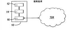
In the communication system such as peer system, client software be installed in such as on the end user device of personal computer (PC) to allow the terminal use to communicate and be identified in user in the communication network via communication network.The user interface that can control client software by the client is with explicit user equipment and show generation such as the event of incoming call.Fig. 1 a is the figure of operation client software with theend user device 10 that directly communicates with peer system.Client software comprisesuser interface layer 12, client'sengine layers 14 and protocol layer.Protocol layer is set to handle the communication between client's engine and thepeer system 104.
Because popularizing of cordless telephone and mobile cellular network, the user can get used to the ambulant conventional telephone service of using simultaneously.Therefore it is desirable to, move client software at the mobile device such as mobile phone or other battery powered cordless apparatus.Yet, bring a series of problems at mobile phone users equipment operation client software.Handheld mobile device is battery powered and have a cpu resource that lacks than PC typically.Be used for the operation client software can reduce battery supply set considerably with the power requirement of handling communication battery life.In addition, can use at the required valuable cpu resource of equipment other application program of operation at subscriber equipment operation client software.
Another problem that causes by use mobile device in the VoIP communication system is in the VoIP system such as peer system, in order to be informed to such as the communication event that receives calling, to be necessary to be connected on the internet constantly.The poor efficiency that lasting connection between maintenance communication network and the internet is not only the battery life of equipment and cpu resource uses, and also is the poor efficiency use to the network connection resource.Being connected to equally constantly on the internet may be that cost is very big concerning the user.The quality that is connected with the internet may be the not good enough quality that therefore reduces communication in addition.
Therefore the purpose of embodiments of the invention is at least one that solve in the above-mentioned validation problem.
Summary of the invention
According to first scheme of the present invention, the method of setting up communication event in a kind of communication system of one from starting device to a plurality of entities relevant with starting device is provided, has said method comprising the steps of: at the first network node place relevant with packet switching network call identification has been distributed at least one entity; The sign of distributing is offered starting device; At the second network node place relevant with packet switching network the correlative connection information of entity is stored with the call identification of distributing to entity; Thereby be transferred to gateway node via the communication event of circuit-switched network startup from the starting device to the entity by the sign that will distribute to entity; Message and the sign of distributing to entity are sent to second network node together to determine the contact details of entity; And via one in circuit switching and the packet switching network contact details of use determining communication event is routed to entity from gateway node but not via first network node communication event is carried out route.
According to alternative plan of the present invention, providing a kind of comprises for communication event is routed to one packet switching network of a plurality of entities relevant with starting device and the communication system of circuit-switched network from starting device, described communication system comprises: first network node, it is arranged in packet switching network, is set to call identification is distributed at least one in the described entity and the sign of distributing offered starting device; Second network node, it is arranged in packet switching network, is set to the correlative connection information of entity is stored together with the call identification of distributing to entity; Gateway node, it is set to receive the communication event that uses the call identification addressing of distributing to entity from starting device via circuit-switched network; Wherein second network node message that further is set to have in response to reception the sign of distributing to entity is determined the contact details of entity and contact details is offered described gateway node, so that communication event can be routed to entity via one circuit switching and the packet switching network from gateway node but not via described first network node described communication event be carried out route.
According to third party's case of the present invention, a kind of network node that is used in the communication system is provided, comprising: the device that is used for the call identification to entity to be allocated is offered another network node that is positioned at communication system; Be used for from the assignment information of other network node receiving entity and the device of contact detail; Be used for using assignment information to store the device of the call identification of the entity relevant with the contact detail of entity; Be used for reception by the device of the call information of the calling of starting device startup, described call information comprises call identification; Be used for the device based on the contact detail of the call information retrieval entity that receives; And be used for thereby the contact detail of receiving equipment is offered the routing node route to the device of the calling of entity.
According to embodiments of the invention, contact details are provided for gateway node.In this case, communication event need not to carry out route via network node.
Description of drawings
In order to understand the present invention better and to represent how to implement the present invention, will be described embodiments of the invention by reference to the accompanying drawings now, in the accompanying drawing:
Figure 1A is the schematic diagram that moves the end user device of client software in order to carry out voip call;
Fig. 1 is that representative is according to the schematic diagram of the communication system of embodiments of the invention;
Fig. 2 is the schematic diagram of the part of representative communication system shown in Figure 1;
Fig. 3 a is that expression is according to the figure of the subscriber equipment of embodiments of the invention;
Fig. 3 b is that expression is according to the figure of the protocol stack of the client program of embodiments of the invention;
Fig. 4 is that expression is according to the figure of the communication path between subscriber equipment and session node of the present invention;
Fig. 5 is the figure that contact person's step is given the PSTN number assignment according to embodiments of the invention in explanation;
Fig. 6 is expression starts the step of calling out in communication system according to embodiments of the invention figure;
Fig. 7 is the figure that expression connects according to the logic of embodiments of the invention between call manager, session node, inbound gateway and departures gateway.
Embodiment
To wherein show thecommunication network 100 that comprises packet-switchedcommunication system 104 and circuit-switchednetwork communication system 104 can be the peer system of moving at the packet switching network such as the internet.Circuit-switchednetwork
For example,subscriber equipment 102 can be personal computer, game machine, personal digital assistant, the suitable mobile phone that activates, and maybe can be connected to the miscellaneous equipment of internet.
The client program of moving atsubscriber equipment 124 has for the some different composition of carrying out multiple function or layer, comprises the protocol layer 402 (Fig. 3 b) that has the interface of GSM network for management.To the interface with GSM network be described in conjunction with Fig. 3 a now.
Fig. 3 a is the schematic diagram that is illustrated in transmission data betweenclient program 124 in thesubscriber equipment 102 and the gsm protocol storehouse.Shown in Fig. 3 a,subscriber equipment 102 further comprises gsm protocol storehouse 501 and wireless set 502.The information that is transferred to subscriber equipment from the GSM network is received by wireless set 502.Handled by gsm protocol storehouse 501 before being transferred toclient program 124 from the data that the GSM network receives.Similarly, will before being transferred to the GSM network via transceiver 502, it be handled by gsm protocol storehouse 501 from the information thatclient program 124 is transferred to the GSM network.The operation of gsm protocol storehouse 501 is in the art by known and will no longer describe in detail herein.
As shown in Figure 1,peer system 104 comprisesinbound gateway 114 and departures gateway 116.Inbound gateway 114 anddepartures gateway 116 are connected to thePSTN gateway 188 that is arranged in the PSTN network.Inbound gateway 114 is set to receive the data that are used for the peer system on theinternet 104 from PSTN gateway 188.Departures gateway 116 is set to data are transferred toPSTN gateway 188 from the peer system on theinternet 104.
Also showprofile node 128 among Fig. 1.Profile node 128 is responsible for user's storing user profile information of peer system.Subscriber profile information comprise for the log-on message of login peer system and with each user-dependent contacts list 132 of peer system.
Login details can limit login name and thereby password allows the user ofsubscriber equipment 102 to login peer-to-peer network and allow the user of subscriber equipment to be identified uniquely in peer system.
For example,contacts list 132 comprises other user's the address that is stored as contact person's communication system by the user.Contact details can limit telephone number, IP (Internet Protocol) address, URI (unified resource identifier), user name, VoIP equipment or can be oncommunication network 100 any other destination address of received communication event.In one embodiment of the invention, the contact details of contact person's tabulation can be included in the tabulation of the destination address in the internet.
To the figure shows the more detailed figure of the part ofcommunication system 100 in conjunction with Fig. 2 now.The element with respect to the describedcommunication system 100 of Fig. 1 that also shows among Fig. 2 is represented by the Reference numeral that shares.Also show circuit-switchednetwork access node 178 andPSTN network gateway 188 and thedata storage 126 relevant withsession node 106 among Fig. 2.Circuit-switchednetwork access node 178 andPSTN network gateway 188 form the part of circuit-switched network 112.Data storage 126 is relevant with call manager.
Now will be in conjunction with Fig. 3 b, Fig. 3 b shows the protocol stack that is used forclient program 124 according to an embodiment of the invention.Protocol stack shows operating system layer 401,protocol layer 402, client's engine layers 404 and client's user interface layer 406.Each layer is responsible for specific function.Because common and other two-layer the communicating of each layer, so they are regarded as being arranged in the storehouse shown in Fig. 3 b.
The data that the hardware resource of operating system layer 401management user devices 102 and processing transfer tosession node 106 and transmit fromsession node 106 via the gsm protocol storehouse.Operating system layer is also handled the data that are transferred tonetwork 112 and transmit fromnetwork 112 via the gsm protocol storehouse.Client agreement layer 402 and the operating system 401 of client software communicate.The process that needs higher level to handle is passed to client's engine layers 404.Client's engine layers 404 also communicates with client's user interface layer 406.Thereby client's engine can be set to control client's user interface layer 406 and via the user interface means of subscriber equipment information be presented to the user.User interface means can comprise loud speaker, microphone, display screen and keyboard.This tabulation is not detailed.
As shown in Figure 4,session node 106 comprises for thenucleus module 205 ofcommunication instance 122 being distributed to client program 124.According to embodiments of the invention, whenclient program 124 was transferred tosession node 106 with logging request,nucleus module 205 was set tocommunication instance 122 is distributed toclient program 124.
Feasible is theprotocol layer 402 uses agreement different with the agreement of using incommunication instance 122 of client program 124.Protocol adaptor in the communication instance helps the communication betweenclient program 124 and thecommunication instance 122.
Compare with Fig. 1 a and it is evident thatsubscriber equipment 102 is the user interface part of operating software only.Carry out the responsible communications portion that communicates with peer-to-peer network atsession node 106 places rather than atsubscriber equipment 102places.Subscriber equipment 102 consumes less battery and cpu resource.
According to embodiments of the invention, therebyclient program 124 is set to will be transferred tosession node 106login peer systems 104 on 111 such as the login details of user login name and password by connecting at packet switched data.Session node is set to once receiving logindetails communication instance 122 be distributed to client program 124.Communication instance 122 is set to check login details and use login details to be registered topeer system 104 by the subscriber profile information that is stored on theprofile node 128 then.
When communication instance was assigned to subscriber equipment, this defined session betweenclient program 124 and thesession node 106 to communicate with peer system 104.Communication instance has produced Session ID and in packet switcheddata connection 111 the session identifier has been transferred toclient program 124.
When beingsubscriber equipment 102 when starting sessions, being set to retrieve with the user-dependent contacts list 132 ofclient program 124 and with at least a portion ofcontacts list 132 in thecommunication instance 122 ofsession node 106 operations and sending to client program 124.Contacts list 132 can be by communication instance from 128 retrievals of profile node.
According to embodiments of the invention, thereby the PSTN number is distributed to each contact person by communication instance and is made client program set up calling to the contact person via the PSTN network.To the method for the PSTN number assignment being given the contact person be described in conjunction with Fig. 5 now.
In step S1,communication instance 122 be set to retrieve with the user-dependent contacts list 132 ofsubscriber equipment 102 in the address of the entity listed as the contact person.Address fromprofile node 128 retrieval entities.
In step S2, communication instance is stored in the address of each entity in the data storage 129.In a preferred embodiment of the invention, whole contacts list is stored in thedata storage 129.
In step S3,122 of communication instance are set to retrieve from call manager the PSTN number of each entity of enumerating contacts list.
In step S4,communication instance 122 is set to give each entity of enumerating with each PSTN number assignment in contacts list, and the address of each entity is reported to call manager with the indication which entity which PSTN number has been assigned to.
In step S5, the address thatcall manager 118 is set to be set forth in each entity in the contacts list is stored in thedata storage 126 relatively with the PSTN number that distributes.
In a preferred embodiment of the invention,call manager 118 is set to also the PSTN number ofsubscriber equipment 102 is stored in thedata storage 126 relatively with the PSTN number of distributing to entity.In step S3 or step S4, the PSTN number of equipment can report to call manager by communication instance.In described embodiment of the present invention, can use the PSTN number of distributing to entity to resolve the address of entity.In this case, a PSTN number can be distributed to the more than one user's use that has in the communication instance ofsession node 106 operations.
The PSTN number of each entity ofcontacts list 132 in distributing to contacts list is transferred toclient program 124 from communicationinstance.Contacts list 132 and the PSTN number that distributes can be stored in the data storage of theaddressable client program 124 that is arranged insubscriber equipment 102 then.
In a preferred embodiment of the invention, the PSTN number that distributes is connected 111 forms with packet withcontacts list 132 via packet switched data and is transferred to client program 124.The PSTN number that distributes can be arranged in the packet that separates withcontacts list 132.
As previously mentioned,client program 124 is set to connect 111 information that receive fromsession node 106 via packet switching.Therebyclient program 124 be set to use the PSTN numbers that distribute that packet switching connects 111 transmission utilize the GSM audio frequency connect 222 start to contacts list 132 ' in the contact person's that enumerates circuit-switched call.An important aspect of the present invention is that circuit switched data such as call data is not viasession node 106 routes.Yet packet switched data such as IM (instant message) and chat data, can utilize contact person's URI viasession node 106 transmission.
According to embodiments of the invention, in the communication event that uses call identifier and contact person to carry out,call manager 118 is set to retrieve contact detail from the contact person ofdata storage 126 in response to the receipt of call identifier.Thereby by call manager retrieve contact detail can offerinbound gateway 114 and allow communication event is carried out route.The logic that Fig. 7 shows betweencall manager 118 andsession node 106 and the gateway 114,116 connects.
Now will be in conjunction with Fig. 6.How Fig. 6 is usedPSTN network 112 to be transferred to the contact person who enumerates in thetabulation 132 by the user of subscriber equipment for expression such as the data in the communication event of calling out.
Calling comprises media data connection and the control data that arrange for the treatment of calling.The control data connection that shows respectively in Fig. 6 for transmitting control data is connected with the media data that is used for transmission of media data.The control data connect and to be represented as solid line and to call out to connect and be represented as dotted line.
In step S100, the user ofsubscriber equipment 102 starts the calling to the entity of enumerating in the contacts list.Contacts list 132 can be shown as the link selected on the display ofsubscriber equipment 102 by the user interface layer of client program 124.The user can be by fetching startup to the calling of this entity for this entity selection chain.When the user started calling,client program 124 was set to dial the PSTN number of distributing to this entity.Therefore the calling of being undertaken byclient program 124 will comprise the control data that limit the PSTN number that distributes.The control data also will comprise the PSTN number of subscriber equipment 102.The PSTN number of being dialled of distributing to entity is connected for being connected with the media data ofPSTN gateway 188 with the control data via GSMaudio frequency connection 222 foundation.
In step 200, the media data connection is maintained at PSTN gateway 188.PSTN gateway 188 is set to transmit control data to the inbound gateway that is arranged in internet 104.PSTN gateway 188 is set to and will comprises that the control data transmission of the PSTN number that identifies is to inbound gateway 114.The PSTN gateway can be provided the number of use by operator's identification of PSTN network bycall manager 118.
In step S300,inbound gateway 114 will comprise that the control data transmission of PSTN number of the PSTN number that distributes of calling entity and subscriber equipment is to call manager 118.The media data connection is maintained atPSTN gateway 188 is resolved out entity until the PSTN number that distributes of calling entity address.
At step S400 place, the PSTN number ofcall manager 118use subscriber equipmenies 102 is searched for the user-dependent contacts list 132 withsubscriber equipment 102 in data storage 126.Then as limiting in thecontacts list 132, distribute to the address that the PSTN of entity is used as entity and position.In one embodiment of the invention, call manager also can be retrieved the user name with the user-dependent user ofsubscriber equipment 102.
In step S500, the address of entity is transferred to inbound gateway 114.Call manager 118 also can be transferred toinbound gateway 114 with the user's ofsubscriber equipment 102 user name.
In step S600, therebyinbound gateway 114 receives from the media data of PSTN gateway and the address of using the entity that receives fromcall manager 118 viapacket switching network 104 call transmissions.Address as sporocarp is arranged in the PSTN network, and then inbound gateway will arrive PSTN network (as shown in Figure 1) with call transfer viadepartures gateway 116.
In step S700, calling is received at the calling entity place, forexample equipment 110a or 110b.If calling entity is arranged ininternet 104, the user's of thesubscriber equipment 102 that then retrieves in step S500 user name can show to show the origin of calling atequipment 110a.
In selectivity embodiment of the present invention, the entity that the user ofsubscriber equipment 102 calls out is not listed as the contact person in contacts list 132.In described embodiment of the present invention,subscriber equipment 102 is set to connect 111 addresses with entity via the exchanges data data before starting the calling of entity and offers communication instance 122.In described embodiment of the present invention, preserve the PSTN number of describing about form 2 that in " call out and arrange " message, limits for the entity of in contacts list, not enumerating.When communication instance received address from the entity of subscriber equipment, the address of entity was stored in thedata storage 126 relatively with the PSTN number of preserving.Then, can call out entity via the PSTN network according to the method step of describing about Fig. 6.
According to one embodiment of present invention, call manager is selected the PSTN number that will distribute according to the positional information of subscriber equipment 102.According to described embodiment, the number that distributes may be with more relevant than the inbound gateway of more close subscriber equipment on the position of other inbound gateway in the communication system, i.e. so-called " local number ".
Although represent especially in conjunction with the preferred embodiments and described the present invention, skilled person will appreciate that the multiple variation that under the situation that does not deviate from the scope of the present invention that claim limits, to make form and details.
Especially, as discussed below, can implement multiple different embodiment.
In selectivity embodiment of the present invention, the PSTN number of subscriber equipment may utilize.In described embodiment of the present invention, the PSTN number that distributes will direct address corresponding to the contact person.Similarly, call manager can only be resolved contact person's address by search for the PSTN number that distributes in data storage.
In one embodiment of the invention,inbound gateway 114 can be set to not receive the media data connection from PSTN gateway 188.In described embodiment of the present invention,inbound gateway 114 is set to contact person's address is offeredPSTN gateway 188, so that the PSTN gateway can carry out route to calling via the PSTN network.When being the PSTN number, contact person's address can use described embodiment of the present invention.
In one embodiment of the invention, the contact person who enumerates in contacts list 132 can be relevant with a plurality of positions in the communication system.For example, can use more than one equipment that the contact person is connected to the internet.Embodiment according to the present invention, contact person's contact detail, for example contact person's user name will be relevant with a plurality of positions in the internet.Similarly, when the user of subscriber equipment set up calling with the contact person, this calling can be received in described a plurality of positions.
Replace one inbound and departures gateway, in one embodiment of the invention, have a plurality of inbound and departures gateway be positioned at communication system 100 (not shown).
In yet another embodiment of the present invention, in the communication system (not shown), can arrange more than more than one call manager.Each call manager can be connected to a different set of session node.
It is relevant withcall manager 118 thatdata storage 126 is represented as.Yet data storage can separate withcall manager 118 on the position.In selectivity embodiment of the present invention,data storage 126 can be relevant with session node and can be visited via session node by call manager 118.In another selectivity embodiment of the present invention, data storage can be positioned atsession node 106 places.In another selectivity embodiment of the present invention, data storage can consist of be separately positioned oncall manager 118 places andsession node 106 places memory cell.
According to one embodiment of the present of invention, the PSTN number that uses for call manager can be provided by the operator ofPSTN network 112.
Other variation is feasible.
Claims (1)
1. the method for the communication event of an entity setting up from starting device to a plurality of entities relevant with described starting device in communication system said method comprising the steps of:
At the first network node place relevant with packet switching network call identification is distributed at least one entity in the described entity;
The sign of described distribution is offered described starting device;
At the second network node place relevant with described packet switching network the correlative connection information of described entity is stored with the described call identification of distributing to described entity;
Thereby be transferred to gateway node via the communication event of circuit-switched network startup from described starting device to described entity by the described sign that will distribute to described entity;
To send to described second network node to determine the contact details of described entity with the described sign of distributing to described entity for the identifier of described starting device; And
Use described definite contact details that described communication event is routed to described entity from described gateway node but not via described first network node described communication event carried out route via one in described circuit-switched network and the packet switching network,
Wherein said first network node is to be set to represent the node that described starting device and packet switching network communicate.
2.The method of claim 1, wherein said first network node are to carry out the node of at least one communication instance, and described at least one communication instance is used for the sign of described distribution is passed to described starting device.
3.Method as claimed in claim 1 or 2, wherein said starting device are to carry out client program to select the mobile device of an entity in the described entity, and described client program is used for user interface is offered the user.
4.Method as claimed in claim 1 or 2 wherein is used for the identifier of described starting device and the described correlative connection information of described entity and stores relatively with the described call identification of distributing to described entity.
5.Method as claimed in claim 1 or 2, the described correlative connection information of wherein said entity limits at least one position in the described communication system.
6.Method as claimed in claim 5, wherein said correlative connection information comprises at least one for the destination address of receiving equipment, PSTN number, user name or VoIP equipment.
7.Method as claimed in claim 1 or 2, wherein said communication event is audio call.
8.Method as claimed in claim 1 or 2, wherein said communication event is video call.
9.Method as claimed in claim 1 or 2, wherein said call identification are the PSTN numbers.
10.A kind ofly comprise that described communication system comprises for the packet switching network of an entity that communication event is routed to a plurality of entities relevant with described starting device from starting device and the communication system of circuit-switched network:
First network node, it is arranged in described packet switching network, be set to call identification is distributed at least one entity in the described entity, the sign of described distribution is offered described starting device, and represent starting device and packet switching network communicates;
Second network node, it is arranged in described packet switching network, is set to the correlative connection information of described entity is stored together with the described call identification of distributing to described entity;
Gateway node, it is set to receive the described communication event that uses the described call identification addressing of distributing to described entity from described starting device via described circuit-switched network;
Wherein said second network node further is set to have in response to reception the message of the described sign of distributing to described entity to be determined the described contact details of described entity and described contact details is offered described gateway node, so that described communication event is routed to described entity from described gateway node via one described circuit-switched network and the packet switching network but not via described first network node described communication event is carried out route.
11.Communication system as claimed in claim 10, wherein relevant with described packet switching network described first network node comprises the node that is set to carry out following at least one communication instance, and described at least one communication instance is used for described sign is delivered to described starting device.
12.A kind of network node that is used in the communication system comprises:
Be used for the call identification to entity to be allocated is offered the device of another network node;
Be used for receiving the assignment information of described entity and the device of contact detail from described another network node, described assignment information comprises that described call identification has been assigned to the indication of entity;
Be used for using the device of the described assignment information storage call identification relevant with the contact detail of described entity;
Be used for receiving the device of the call information that is used for calling that is started by starting device, described call information comprises described call identification;
Be used for using the described call information that receives to retrieve the device of the described contact detail of described entity; And
Be used for thereby the described contact detail of described entity is offered the routing node route to the device of the calling of described entity.
Applications Claiming Priority (5)
| Application Number | Priority Date | Filing Date | Title |
|---|---|---|---|
| GB0623622.8 | 2006-11-27 | ||
| GBGB0623622.8AGB0623622D0 (en) | 2006-11-27 | 2006-11-27 | Communication system |
| GB0723123.6 | 2007-11-23 | ||
| GB0723123AGB2445065B (en) | 2006-11-27 | 2007-11-23 | Communication system |
| PCT/IB2007/004259WO2008065533A2 (en) | 2006-11-27 | 2007-11-27 | Communication system |
Publications (2)
| Publication Number | Publication Date |
|---|---|
| CN101543013A CN101543013A (en) | 2009-09-23 |
| CN101543013Btrue CN101543013B (en) | 2013-08-28 |
Family
ID=37636578
Family Applications (1)
| Application Number | Title | Priority Date | Filing Date |
|---|---|---|---|
| CN2007800441110AActiveCN101543013B (en) | 2006-11-27 | 2007-11-27 | Communication system |
Country Status (6)
| Country | Link |
|---|---|
| US (1) | US8711841B2 (en) |
| EP (1) | EP2090057B1 (en) |
| CN (1) | CN101543013B (en) |
| GB (2) | GB0623622D0 (en) |
| IL (1) | IL198885A (en) |
| WO (1) | WO2008065533A2 (en) |
Families Citing this family (6)
| Publication number | Priority date | Publication date | Assignee | Title |
|---|---|---|---|---|
| GB2443889A (en) | 2006-11-20 | 2008-05-21 | Skype Ltd | Method and system for anonymous communication |
| GB0623621D0 (en) | 2006-11-27 | 2007-01-03 | Skype Ltd | Communication system |
| GB0623622D0 (en) | 2006-11-27 | 2007-01-03 | Skype Ltd | Communication system |
| US8660246B1 (en) | 2009-04-06 | 2014-02-25 | Wendell Brown | Method and apparatus for content presentation in association with a telephone call |
| WO2012136005A1 (en)* | 2011-04-08 | 2012-10-11 | Zte Corporation | A method for addressing a m2m terminal and a m2m platform device |
| WO2016168909A1 (en)* | 2015-04-20 | 2016-10-27 | Topology Lp | Communicating in a peer-to-peer network |
Family Cites Families (71)
| Publication number | Priority date | Publication date | Assignee | Title |
|---|---|---|---|---|
| CA2129199C (en) | 1994-07-29 | 1999-07-20 | Roger Y.M. Cheung | Method and apparatus for bridging wireless lan to a wired lan |
| US6061363A (en)* | 1997-12-01 | 2000-05-09 | Nortel Networks Corporation | Communications system with load sharing communications interface |
| WO1999067922A1 (en) | 1998-06-25 | 1999-12-29 | Mci Worldcom, Inc. | Method and system for multicasting call notifications |
| US6088433A (en)* | 1998-07-09 | 2000-07-11 | Sbc Technology Resources, Inc. | System and method for forwarding call from disconnected telephone number to new telephone number |
| US6810034B1 (en)* | 1999-02-26 | 2004-10-26 | Avaya Technology Corp. | Automatic conversion of telephone number to internet protocol address |
| US7388953B2 (en) | 1999-09-24 | 2008-06-17 | Verizon Business Global Llc | Method and system for providing intelligent network control services in IP telephony |
| CN1415159A (en) | 1999-09-24 | 2003-04-30 | 戴尔帕德通讯公司 | Flexible communications system |
| JP4207337B2 (en) | 1999-11-11 | 2009-01-14 | ソニー株式会社 | Communication system and communication method |
| US6798767B1 (en)* | 1999-11-16 | 2004-09-28 | Cisco Technology, Inc. | System and method for generating multiple line appearances in a communication network |
| IL149821A0 (en) | 1999-11-26 | 2002-11-10 | Mobile Telephone Networks Prop | Communication method and system |
| AU3272501A (en) | 1999-11-30 | 2001-06-12 | Acallto, Inc. | Establishing a communication link between parties |
| AU4139201A (en)* | 1999-12-01 | 2001-06-12 | Wireless Internet, Inc. | Improvements in remote call-to-action messaging |
| KR100404137B1 (en) | 2000-02-25 | 2003-11-01 | 신광섭 | Internet interconnection method and internet interconnection system thereof |
| FI109443B (en)* | 2000-03-16 | 2002-07-31 | Nokia Corp | Updating subscriber data |
| US6765921B1 (en)* | 2000-06-28 | 2004-07-20 | Nortel Networks Limited | Communications network |
| US20020071539A1 (en)* | 2000-07-25 | 2002-06-13 | Marc Diament | Method and apparatus for telephony-enabled instant messaging |
| US20020071424A1 (en)* | 2000-12-12 | 2002-06-13 | Chiu King W. | Packet voice telephony apparatus and method |
| WO2002057917A2 (en)* | 2001-01-22 | 2002-07-25 | Sun Microsystems, Inc. | Peer-to-peer network computing platform |
| US7043644B2 (en)* | 2001-01-31 | 2006-05-09 | Qurio Holdings, Inc. | Facilitating file access from firewall-protected nodes in a peer-to-peer network |
| US20020116464A1 (en)* | 2001-02-20 | 2002-08-22 | Mak Joon Mun | Electronic communications system and method |
| US7003079B1 (en)* | 2001-03-05 | 2006-02-21 | Bbnt Solutions Llc | Apparatus and method for monitoring performance of an automated response system |
| SE520393C2 (en) | 2001-03-22 | 2003-07-01 | Columbitech Ab | Method of communication through firewall |
| US6920318B2 (en)* | 2001-03-22 | 2005-07-19 | Siemens Communications, Inc. | Method and system for providing message services in a communication system |
| US7403517B2 (en)* | 2001-06-20 | 2008-07-22 | Nokia Corporation | System, device and method for providing call forwarding in dual subscription mode |
| US6700884B2 (en)* | 2001-06-28 | 2004-03-02 | Emerson, Iii Harry E. | Integrating the Internet with the public switched telephone network |
| WO2003014955A1 (en)* | 2001-08-09 | 2003-02-20 | Gigamedia Access Corporation | Hybrid system architecture for secure peer-to-peer-communication |
| US7207008B1 (en)* | 2001-09-12 | 2007-04-17 | Bellsouth Intellectual Property Corp. | Method, system, apparatus, and computer-readable medium for interactive notification of events |
| US7227864B2 (en)* | 2001-12-17 | 2007-06-05 | Microsoft Corporation | Methods and systems for establishing communications through firewalls and network address translators |
| EP1333637A1 (en) | 2002-01-31 | 2003-08-06 | Koninklijke KPN N.V. | Telecommunication method and system |
| CN1215386C (en)* | 2002-04-26 | 2005-08-17 | St微电子公司 | Method and hardware architecture for controlling a process or processing data according to quantum soft computing |
| US7221945B2 (en)* | 2002-05-03 | 2007-05-22 | Leapstone Systems, Inc. | System and method for establishing and controlling access to network resources |
| US20030227902A1 (en)* | 2002-06-06 | 2003-12-11 | Benjamin Lindquist | System for connecting computer-requested telephone calls using a distributed network of gateways |
| CN1659814A (en)* | 2002-06-06 | 2005-08-24 | 汤姆森特许公司 | WLAN as a Logical Support Node (SGSN) interworking between WLAN and mobile communication systems |
| EP1408704A1 (en) | 2002-10-09 | 2004-04-14 | Nokia Corporation | Method and arrangement for concealing true identity of user in communications system |
| US6999458B2 (en)* | 2003-02-14 | 2006-02-14 | Theglobe.Com | Internet telephony network and methods for using the same |
| GB2398458B (en)* | 2003-02-15 | 2005-05-25 | Ericsson Telefon Ab L M | Conversational bearer negotiation |
| GB2405285B (en) | 2003-04-11 | 2006-01-11 | Hutchison Whampoa Three G Ip | Real-time communications between telephone and internet users |
| JP4115354B2 (en)* | 2003-07-04 | 2008-07-09 | 富士フイルム株式会社 | Peer-to-peer communication system |
| US7177837B2 (en)* | 2003-07-11 | 2007-02-13 | Pascal Pegaz-Paquet | Computer-implemented method and system for managing accounting and billing of transactions over public media such as the internet |
| WO2005009019A2 (en) | 2003-07-16 | 2005-01-27 | Skype Limited | Peer-to-peer telephone system and method |
| DE60311155T2 (en)* | 2003-08-19 | 2007-10-18 | Ntt Docomo Inc. | ACCURATE CONTROL OF INFORMATION TRANSMISSIONS IN AD-HOC NETWORKS |
| EP1515506A1 (en) | 2003-09-09 | 2005-03-16 | Alcatel | A method of establishing a data packet communication session between a terminal arrangements of a data packet network and an exchange therefore |
| US7120235B2 (en)* | 2003-10-06 | 2006-10-10 | Ingenio, Inc. | Method and apparatus to provide pay-per-call performance based advertising |
| CN100592735C (en)* | 2003-10-24 | 2010-02-24 | 艾利森电话股份有限公司 | Means and method for controlling service progression between different domains |
| US20050117735A1 (en)* | 2003-12-02 | 2005-06-02 | Seidman James L. | Method for load distribution with multiple distribution points |
| MXPA06006066A (en) | 2003-12-05 | 2006-08-11 | Utstarcom Inc | Method for remote service forwarding (rsf) between dissimilar systems with operator, service and location portability. |
| US7565436B2 (en)* | 2003-12-24 | 2009-07-21 | Nortel Networks Limited | Ethernet to frame relay interworking with multiple quality of service levels |
| US20050141509A1 (en)* | 2003-12-24 | 2005-06-30 | Sameh Rabie | Ethernet to ATM interworking with multiple quality of service levels |
| WO2005084128A2 (en)* | 2004-03-04 | 2005-09-15 | Outsmart Ltd. | Integration of packet and cellular telephone networks |
| DE102004028124B4 (en)* | 2004-06-09 | 2008-08-07 | Siemens Ag | Multi-mode imaging tomography device and method for changing the operating mode of the tomographic device |
| US7656870B2 (en)* | 2004-06-29 | 2010-02-02 | Damaka, Inc. | System and method for peer-to-peer hybrid communications |
| DE102004032225B4 (en) | 2004-07-02 | 2007-07-12 | Siemens Ag | Method and device for setting up and operating a communication connection |
| US7298833B2 (en)* | 2004-09-29 | 2007-11-20 | Avaya Integrated Cabinet Solutions, Inc. | Wireless device to manage cross-network telecommunication services |
| US20060072547A1 (en) | 2004-09-29 | 2006-04-06 | Lucent Technologies Inc. | Systems and methods for serving VolP emergency calls |
| JP2008522501A (en)* | 2004-11-24 | 2008-06-26 | トークプラス、インコーポレイテッド | User controlled telecommunications system |
| US7839992B2 (en)* | 2004-12-28 | 2010-11-23 | At&T Intellectual Property Ii, L.P. | Method and apparatus for registering multiple phone numbers associated with a frequently called party |
| WO2006095787A1 (en) | 2005-03-10 | 2006-09-14 | Matsushita Electric Industrial Co., Ltd. | Relay device |
| US9363384B2 (en)* | 2005-04-06 | 2016-06-07 | Qwest Communications International Inc. | Systems for delivering calls on dual-mode wireless handsets |
| CN101518042B (en)* | 2005-04-12 | 2013-06-12 | 电信系统有限公司 | Temporary enum gateway |
| US8244179B2 (en)* | 2005-05-12 | 2012-08-14 | Robin Dua | Wireless inter-device data processing configured through inter-device transmitted data |
| US7920549B2 (en)* | 2005-07-20 | 2011-04-05 | Verizon Business Global Llc | Method and system for providing secure media gateways to support interdomain traversal |
| US7756548B2 (en)* | 2005-09-19 | 2010-07-13 | Qualcomm Incorporated | Methods and apparatus for use in a wireless communications system that uses a multi-mode base station |
| US7567791B2 (en)* | 2005-09-19 | 2009-07-28 | Qualcomm Incorporated | Wireless terminal methods and apparatus for use in a wireless communications system that uses a multi-mode base station |
| US7298714B2 (en)* | 2005-10-04 | 2007-11-20 | Yahoo! Inc. | Peer-to-peer message chaining for initiating a data exchange with a server |
| US7644121B2 (en)* | 2005-11-30 | 2010-01-05 | Clickpath, Llc | Method and system for online session tracking |
| US20070160034A1 (en)* | 2006-01-06 | 2007-07-12 | D.S.P. Group Ltd | Dual-protocol dual port telephone and method to connect another dual-protocol dual port telephone via IP network directly and without installation |
| US20070238472A1 (en)* | 2006-04-05 | 2007-10-11 | James Andrew Wanless | Method and system for smart route dialling to a destination identifier using a telephone |
| US7929955B1 (en)* | 2006-04-28 | 2011-04-19 | At&T Mobility Ii Llc | Managing multiple CLI identities |
| GB2443889A (en) | 2006-11-20 | 2008-05-21 | Skype Ltd | Method and system for anonymous communication |
| GB0623622D0 (en) | 2006-11-27 | 2007-01-03 | Skype Ltd | Communication system |
| GB0623621D0 (en)* | 2006-11-27 | 2007-01-03 | Skype Ltd | Communication system |
- 2006
- 2006-11-27GBGBGB0623622.8Apatent/GB0623622D0/ennot_activeCeased
- 2007
- 2007-11-23GBGB0723123Apatent/GB2445065B/ennot_activeExpired - Fee Related
- 2007-11-27USUS11/986,985patent/US8711841B2/enactiveActive
- 2007-11-27EPEP07859297.9Apatent/EP2090057B1/enactiveActive
- 2007-11-27CNCN2007800441110Apatent/CN101543013B/enactiveActive
- 2007-11-27WOPCT/IB2007/004259patent/WO2008065533A2/enactiveApplication Filing
- 2009
- 2009-05-21ILIL198885Apatent/IL198885A/enactiveIP Right Grant
Also Published As
| Publication number | Publication date |
|---|---|
| WO2008065533A3 (en) | 2008-08-28 |
| GB2445065A (en) | 2008-06-25 |
| IL198885A0 (en) | 2010-02-17 |
| GB0723123D0 (en) | 2008-01-02 |
| EP2090057B1 (en) | 2016-06-15 |
| GB2445065B (en) | 2011-06-22 |
| EP2090057A2 (en) | 2009-08-19 |
| US20080192734A1 (en) | 2008-08-14 |
| GB0623622D0 (en) | 2007-01-03 |
| WO2008065533A2 (en) | 2008-06-05 |
| CN101543013A (en) | 2009-09-23 |
| US8711841B2 (en) | 2014-04-29 |
| IL198885A (en) | 2013-07-31 |
Similar Documents
| Publication | Publication Date | Title |
|---|---|---|
| CN101543012B (en) | Communication system | |
| AU2011201143B2 (en) | Caller-callee association of a plurality of networked devices | |
| US20140323103A1 (en) | Caller-callee association of a plurality of networked devices with direct dial through thin client | |
| CA2495093A1 (en) | Providing routing information in a communication system | |
| JP5351765B2 (en) | Method and apparatus for linking identification data to calls between networks | |
| CN101543013B (en) | Communication system | |
| US7756257B2 (en) | SIP enabled device identification | |
| JP4983325B2 (en) | How to provide a nickname telephone service using mobile Internet technology | |
| SE517319C2 (en) | Systems and devices in private telecommunications systems where IP networks are used for signaling regarding inquiry and response messages | |
| JP2020047974A (en) | Telephone system | |
| JP4964148B2 (en) | Method and server in a cellular telecommunications network provided for different routing | |
| JP4050585B2 (en) | Telephone network system, gatekeeper device and call connection method thereof | |
| JP6414436B2 (en) | Telephone system, master telephone control device, slave telephone control device, and system information setting method | |
| MX2008000206A (en) | Caller-callee association of a plurality of networked devices | |
| JP2010087825A (en) | System and device for controlling communication, local area communication device and method for controlling communication |
Legal Events
| Date | Code | Title | Description |
|---|---|---|---|
| C06 | Publication | ||
| PB01 | Publication | ||
| C10 | Entry into substantive examination | ||
| SE01 | Entry into force of request for substantive examination | ||
| C53 | Correction of patent of invention or patent application | ||
| CB02 | Change of applicant information | Address after:Dublin, Ireland Applicant after:Scape Co., Ltd. Address before:Dublin, Ireland Applicant before:Skyper Ltd. | |
| COR | Change of bibliographic data | Free format text:CORRECT: APPLICANT; FROM: SKYPER LTD. TO: SKYPE LTD. | |
| C14 | Grant of patent or utility model | ||
| GR01 | Patent grant | ||
| TR01 | Transfer of patent right | ||
| TR01 | Transfer of patent right | Effective date of registration:20200507 Address after:Washington State Patentee after:MICROSOFT TECHNOLOGY LICENSING, LLC Address before:Ai Erlandubailin Patentee before:Skype |