CN101541367B - Catheters used in breathing apparatus - Google Patents
Catheters used in breathing apparatusDownload PDFInfo
- Publication number
- CN101541367B CN101541367BCN200780044030.0ACN200780044030ACN101541367BCN 101541367 BCN101541367 BCN 101541367BCN 200780044030 ACN200780044030 ACN 200780044030ACN 101541367 BCN101541367 BCN 101541367B
- Authority
- CN
- China
- Prior art keywords
- conduit
- power supply
- constructed
- patient
- wires
- Prior art date
- Legal status (The legal status is an assumption and is not a legal conclusion. Google has not performed a legal analysis and makes no representation as to the accuracy of the status listed.)
- Expired - Fee Related
Links
Images


Classifications
- A—HUMAN NECESSITIES
- A61—MEDICAL OR VETERINARY SCIENCE; HYGIENE
- A61M—DEVICES FOR INTRODUCING MEDIA INTO, OR ONTO, THE BODY; DEVICES FOR TRANSDUCING BODY MEDIA OR FOR TAKING MEDIA FROM THE BODY; DEVICES FOR PRODUCING OR ENDING SLEEP OR STUPOR
- A61M16/00—Devices for influencing the respiratory system of patients by gas treatment, e.g. ventilators; Tracheal tubes
- A61M16/10—Preparation of respiratory gases or vapours
- A61M16/1075—Preparation of respiratory gases or vapours by influencing the temperature
- A—HUMAN NECESSITIES
- A61—MEDICAL OR VETERINARY SCIENCE; HYGIENE
- A61M—DEVICES FOR INTRODUCING MEDIA INTO, OR ONTO, THE BODY; DEVICES FOR TRANSDUCING BODY MEDIA OR FOR TAKING MEDIA FROM THE BODY; DEVICES FOR PRODUCING OR ENDING SLEEP OR STUPOR
- A61M16/00—Devices for influencing the respiratory system of patients by gas treatment, e.g. ventilators; Tracheal tubes
- A61M16/0003—Accessories therefor, e.g. sensors, vibrators, negative pressure
- A—HUMAN NECESSITIES
- A61—MEDICAL OR VETERINARY SCIENCE; HYGIENE
- A61M—DEVICES FOR INTRODUCING MEDIA INTO, OR ONTO, THE BODY; DEVICES FOR TRANSDUCING BODY MEDIA OR FOR TAKING MEDIA FROM THE BODY; DEVICES FOR PRODUCING OR ENDING SLEEP OR STUPOR
- A61M16/00—Devices for influencing the respiratory system of patients by gas treatment, e.g. ventilators; Tracheal tubes
- A61M16/0057—Pumps therefor
- A—HUMAN NECESSITIES
- A61—MEDICAL OR VETERINARY SCIENCE; HYGIENE
- A61M—DEVICES FOR INTRODUCING MEDIA INTO, OR ONTO, THE BODY; DEVICES FOR TRANSDUCING BODY MEDIA OR FOR TAKING MEDIA FROM THE BODY; DEVICES FOR PRODUCING OR ENDING SLEEP OR STUPOR
- A61M16/00—Devices for influencing the respiratory system of patients by gas treatment, e.g. ventilators; Tracheal tubes
- A61M16/06—Respiratory or anaesthetic masks
- A—HUMAN NECESSITIES
- A61—MEDICAL OR VETERINARY SCIENCE; HYGIENE
- A61M—DEVICES FOR INTRODUCING MEDIA INTO, OR ONTO, THE BODY; DEVICES FOR TRANSDUCING BODY MEDIA OR FOR TAKING MEDIA FROM THE BODY; DEVICES FOR PRODUCING OR ENDING SLEEP OR STUPOR
- A61M16/00—Devices for influencing the respiratory system of patients by gas treatment, e.g. ventilators; Tracheal tubes
- A61M16/08—Bellows; Connecting tubes ; Water traps; Patient circuits
- A61M16/0816—Joints or connectors
- A61M16/0825—Joints or connectors with ball-sockets
- A—HUMAN NECESSITIES
- A61—MEDICAL OR VETERINARY SCIENCE; HYGIENE
- A61M—DEVICES FOR INTRODUCING MEDIA INTO, OR ONTO, THE BODY; DEVICES FOR TRANSDUCING BODY MEDIA OR FOR TAKING MEDIA FROM THE BODY; DEVICES FOR PRODUCING OR ENDING SLEEP OR STUPOR
- A61M16/00—Devices for influencing the respiratory system of patients by gas treatment, e.g. ventilators; Tracheal tubes
- A61M16/08—Bellows; Connecting tubes ; Water traps; Patient circuits
- A61M16/0875—Connecting tubes
- A—HUMAN NECESSITIES
- A61—MEDICAL OR VETERINARY SCIENCE; HYGIENE
- A61M—DEVICES FOR INTRODUCING MEDIA INTO, OR ONTO, THE BODY; DEVICES FOR TRANSDUCING BODY MEDIA OR FOR TAKING MEDIA FROM THE BODY; DEVICES FOR PRODUCING OR ENDING SLEEP OR STUPOR
- A61M16/00—Devices for influencing the respiratory system of patients by gas treatment, e.g. ventilators; Tracheal tubes
- A61M16/10—Preparation of respiratory gases or vapours
- A61M16/1075—Preparation of respiratory gases or vapours by influencing the temperature
- A61M16/108—Preparation of respiratory gases or vapours by influencing the temperature before being humidified or mixed with a beneficial agent
- A—HUMAN NECESSITIES
- A61—MEDICAL OR VETERINARY SCIENCE; HYGIENE
- A61M—DEVICES FOR INTRODUCING MEDIA INTO, OR ONTO, THE BODY; DEVICES FOR TRANSDUCING BODY MEDIA OR FOR TAKING MEDIA FROM THE BODY; DEVICES FOR PRODUCING OR ENDING SLEEP OR STUPOR
- A61M16/00—Devices for influencing the respiratory system of patients by gas treatment, e.g. ventilators; Tracheal tubes
- A61M16/10—Preparation of respiratory gases or vapours
- A61M16/1075—Preparation of respiratory gases or vapours by influencing the temperature
- A61M16/1085—Preparation of respiratory gases or vapours by influencing the temperature after being humidified or mixed with a beneficial agent
- A—HUMAN NECESSITIES
- A61—MEDICAL OR VETERINARY SCIENCE; HYGIENE
- A61M—DEVICES FOR INTRODUCING MEDIA INTO, OR ONTO, THE BODY; DEVICES FOR TRANSDUCING BODY MEDIA OR FOR TAKING MEDIA FROM THE BODY; DEVICES FOR PRODUCING OR ENDING SLEEP OR STUPOR
- A61M16/00—Devices for influencing the respiratory system of patients by gas treatment, e.g. ventilators; Tracheal tubes
- A61M16/10—Preparation of respiratory gases or vapours
- A61M16/1075—Preparation of respiratory gases or vapours by influencing the temperature
- A61M16/109—Preparation of respiratory gases or vapours by influencing the temperature the humidifying liquid or the beneficial agent
- A—HUMAN NECESSITIES
- A61—MEDICAL OR VETERINARY SCIENCE; HYGIENE
- A61M—DEVICES FOR INTRODUCING MEDIA INTO, OR ONTO, THE BODY; DEVICES FOR TRANSDUCING BODY MEDIA OR FOR TAKING MEDIA FROM THE BODY; DEVICES FOR PRODUCING OR ENDING SLEEP OR STUPOR
- A61M16/00—Devices for influencing the respiratory system of patients by gas treatment, e.g. ventilators; Tracheal tubes
- A61M16/10—Preparation of respiratory gases or vapours
- A61M16/1075—Preparation of respiratory gases or vapours by influencing the temperature
- A61M16/1095—Preparation of respiratory gases or vapours by influencing the temperature in the connecting tubes
- A—HUMAN NECESSITIES
- A61—MEDICAL OR VETERINARY SCIENCE; HYGIENE
- A61M—DEVICES FOR INTRODUCING MEDIA INTO, OR ONTO, THE BODY; DEVICES FOR TRANSDUCING BODY MEDIA OR FOR TAKING MEDIA FROM THE BODY; DEVICES FOR PRODUCING OR ENDING SLEEP OR STUPOR
- A61M16/00—Devices for influencing the respiratory system of patients by gas treatment, e.g. ventilators; Tracheal tubes
- A61M16/10—Preparation of respiratory gases or vapours
- A61M16/14—Preparation of respiratory gases or vapours by mixing different fluids, one of them being in a liquid phase
- A61M16/16—Devices to humidify the respiration air
- A—HUMAN NECESSITIES
- A61—MEDICAL OR VETERINARY SCIENCE; HYGIENE
- A61M—DEVICES FOR INTRODUCING MEDIA INTO, OR ONTO, THE BODY; DEVICES FOR TRANSDUCING BODY MEDIA OR FOR TAKING MEDIA FROM THE BODY; DEVICES FOR PRODUCING OR ENDING SLEEP OR STUPOR
- A61M16/00—Devices for influencing the respiratory system of patients by gas treatment, e.g. ventilators; Tracheal tubes
- A61M16/08—Bellows; Connecting tubes ; Water traps; Patient circuits
- A61M16/0816—Joints or connectors
- A—HUMAN NECESSITIES
- A61—MEDICAL OR VETERINARY SCIENCE; HYGIENE
- A61M—DEVICES FOR INTRODUCING MEDIA INTO, OR ONTO, THE BODY; DEVICES FOR TRANSDUCING BODY MEDIA OR FOR TAKING MEDIA FROM THE BODY; DEVICES FOR PRODUCING OR ENDING SLEEP OR STUPOR
- A61M16/00—Devices for influencing the respiratory system of patients by gas treatment, e.g. ventilators; Tracheal tubes
- A61M16/10—Preparation of respiratory gases or vapours
- A61M16/14—Preparation of respiratory gases or vapours by mixing different fluids, one of them being in a liquid phase
- A61M16/16—Devices to humidify the respiration air
- A61M16/161—Devices to humidify the respiration air with means for measuring the humidity
- A—HUMAN NECESSITIES
- A61—MEDICAL OR VETERINARY SCIENCE; HYGIENE
- A61M—DEVICES FOR INTRODUCING MEDIA INTO, OR ONTO, THE BODY; DEVICES FOR TRANSDUCING BODY MEDIA OR FOR TAKING MEDIA FROM THE BODY; DEVICES FOR PRODUCING OR ENDING SLEEP OR STUPOR
- A61M16/00—Devices for influencing the respiratory system of patients by gas treatment, e.g. ventilators; Tracheal tubes
- A61M16/0003—Accessories therefor, e.g. sensors, vibrators, negative pressure
- A61M2016/0027—Accessories therefor, e.g. sensors, vibrators, negative pressure pressure meter
- A—HUMAN NECESSITIES
- A61—MEDICAL OR VETERINARY SCIENCE; HYGIENE
- A61M—DEVICES FOR INTRODUCING MEDIA INTO, OR ONTO, THE BODY; DEVICES FOR TRANSDUCING BODY MEDIA OR FOR TAKING MEDIA FROM THE BODY; DEVICES FOR PRODUCING OR ENDING SLEEP OR STUPOR
- A61M2205/00—General characteristics of the apparatus
- A61M2205/14—Detection of the presence or absence of a tube, a connector or a container in an apparatus
- A—HUMAN NECESSITIES
- A61—MEDICAL OR VETERINARY SCIENCE; HYGIENE
- A61M—DEVICES FOR INTRODUCING MEDIA INTO, OR ONTO, THE BODY; DEVICES FOR TRANSDUCING BODY MEDIA OR FOR TAKING MEDIA FROM THE BODY; DEVICES FOR PRODUCING OR ENDING SLEEP OR STUPOR
- A61M2205/00—General characteristics of the apparatus
- A61M2205/33—Controlling, regulating or measuring
- A61M2205/3331—Pressure; Flow
- A61M2205/3334—Measuring or controlling the flow rate
- A—HUMAN NECESSITIES
- A61—MEDICAL OR VETERINARY SCIENCE; HYGIENE
- A61M—DEVICES FOR INTRODUCING MEDIA INTO, OR ONTO, THE BODY; DEVICES FOR TRANSDUCING BODY MEDIA OR FOR TAKING MEDIA FROM THE BODY; DEVICES FOR PRODUCING OR ENDING SLEEP OR STUPOR
- A61M2205/00—General characteristics of the apparatus
- A61M2205/33—Controlling, regulating or measuring
- A61M2205/3368—Temperature
- A—HUMAN NECESSITIES
- A61—MEDICAL OR VETERINARY SCIENCE; HYGIENE
- A61M—DEVICES FOR INTRODUCING MEDIA INTO, OR ONTO, THE BODY; DEVICES FOR TRANSDUCING BODY MEDIA OR FOR TAKING MEDIA FROM THE BODY; DEVICES FOR PRODUCING OR ENDING SLEEP OR STUPOR
- A61M2205/00—General characteristics of the apparatus
- A61M2205/33—Controlling, regulating or measuring
- A61M2205/3375—Acoustical, e.g. ultrasonic, measuring means
- A—HUMAN NECESSITIES
- A61—MEDICAL OR VETERINARY SCIENCE; HYGIENE
- A61M—DEVICES FOR INTRODUCING MEDIA INTO, OR ONTO, THE BODY; DEVICES FOR TRANSDUCING BODY MEDIA OR FOR TAKING MEDIA FROM THE BODY; DEVICES FOR PRODUCING OR ENDING SLEEP OR STUPOR
- A61M2205/00—General characteristics of the apparatus
- A61M2205/60—General characteristics of the apparatus with identification means
- A61M2205/6018—General characteristics of the apparatus with identification means providing set-up signals for the apparatus configuration
- A—HUMAN NECESSITIES
- A61—MEDICAL OR VETERINARY SCIENCE; HYGIENE
- A61M—DEVICES FOR INTRODUCING MEDIA INTO, OR ONTO, THE BODY; DEVICES FOR TRANSDUCING BODY MEDIA OR FOR TAKING MEDIA FROM THE BODY; DEVICES FOR PRODUCING OR ENDING SLEEP OR STUPOR
- A61M2205/00—General characteristics of the apparatus
- A61M2205/60—General characteristics of the apparatus with identification means
- A61M2205/6054—Magnetic identification systems
- A—HUMAN NECESSITIES
- A61—MEDICAL OR VETERINARY SCIENCE; HYGIENE
- A61M—DEVICES FOR INTRODUCING MEDIA INTO, OR ONTO, THE BODY; DEVICES FOR TRANSDUCING BODY MEDIA OR FOR TAKING MEDIA FROM THE BODY; DEVICES FOR PRODUCING OR ENDING SLEEP OR STUPOR
- A61M2230/00—Measuring parameters of the user
- A61M2230/04—Heartbeat characteristics, e.g. ECG, blood pressure modulation
Landscapes
- Health & Medical Sciences (AREA)
- General Health & Medical Sciences (AREA)
- Veterinary Medicine (AREA)
- Engineering & Computer Science (AREA)
- Anesthesiology (AREA)
- Biomedical Technology (AREA)
- Heart & Thoracic Surgery (AREA)
- Hematology (AREA)
- Life Sciences & Earth Sciences (AREA)
- Animal Behavior & Ethology (AREA)
- Emergency Medicine (AREA)
- Pulmonology (AREA)
- Public Health (AREA)
- Thermotherapy And Cooling Therapy Devices (AREA)
- Respiratory Apparatuses And Protective Means (AREA)
- Devices For Medical Bathing And Washing (AREA)
- Air Humidification (AREA)
- Infusion, Injection, And Reservoir Apparatuses (AREA)
- Media Introduction/Drainage Providing Device (AREA)
- Measurement Of The Respiration, Hearing Ability, Form, And Blood Characteristics Of Living Organisms (AREA)
- Percussion Or Vibration Massage (AREA)
- Accommodation For Nursing Or Treatment Tables (AREA)
Abstract
Description
Translated fromChinese相关申请的交叉引用Cross References to Related Applications
本发明要求享有于2007年8月10日提交的美国申请60/955,222和2006年11月8日提交的澳大利亚临时申请2006906224的优先权,两者的全部内容通过引用合并在此。This application claims priority to US Application 60/955,222, filed 10 August 2007, and Australian Provisional Application 2006906224, filed 8 November 2006, the entire contents of which are incorporated herein by reference.
技术领域technical field
本发明涉及加湿和加热器设备,其用于控制在所有形式的呼吸装置通气系统中使用的可吸入气体的湿度,所有形式的呼吸装置包括用于诸如阻塞性睡眠呼吸暂停(OSA)的睡眠障碍呼吸(SDB)以及用于各种其它呼吸障碍和疾病的侵入性和非侵入性通气、持续正通气压力(CPAP)、双水平疗法和治疗。The present invention relates to humidification and heater apparatus for controlling the humidity of breathable gas used in ventilation systems of all forms of breathing apparatus including those for sleep disorders such as obstructive sleep apnea (OSA) Breathing (SDB) and invasive and non-invasive ventilation, continuous positive airway pressure (CPAP), bilevel therapy and therapy for a variety of other respiratory disorders and diseases.
背景技术Background technique
为了降低患者气道的干燥以及随后引起的患者的不适和相关的并发症,呼吸装置通常具有改变可吸入气体的湿度的能力。在流体发生器和患者面罩之间的加湿器的使用产生了可以使鼻粘膜的干燥最小化并提高了患者气道的舒适的湿化气体。另外在较冷的气候条件下,由于泄露偶然会发生暖空气施加在面罩周围的面部区域上,大致施加在面罩内部和周围的面部区域上的暖空气比冷空气更加舒适。To reduce drying of the patient's airway and subsequent patient discomfort and associated complications, respiratory devices often have the ability to alter the humidity of the breathable gas. The use of a humidifier between the flow generator and the patient's mask produces humidified air that minimizes drying of the nasal mucosa and enhances the comfort of the patient's airway. Also in colder climates, warm air applied to the face area around the face mask in general is more comfortable than cold air due to leaks that occasionally occur on the face area surrounding the mask.
可以见到很多加湿器类型,尽管最方便的形式是其或者与相关的呼吸装置结合或者构造为连接至相关的呼吸装置。尽管被动加湿器能够提供一些缓解,但是通常需要加热型加湿器为空气提供足够的湿度和温度以使患者舒适。加湿器典型地包括:具有几百毫升容量的水桶、用于加热桶中的水的加热元件、能够使加湿程度变化的控制器、用于接受来自流体发生器气体的气体入口,以及适于连接至将湿化的加压气体传递至患者面罩的患者导管的气体出口。Many humidifier types are available, although in the most convenient form they are either combined with or configured to be connected to an associated breathing apparatus. While passive humidifiers can provide some relief, heated humidifiers are often required to provide the air with sufficient humidity and temperature for patient comfort. Humidifiers typically include: a water tank with a capacity of several hundred milliliters, a heating element for heating the water in the tank, a controller that enables the degree of humidification to be varied, a gas inlet for receiving gas from a fluid generator, and suitable connections To the gas outlet of the patient conduit that delivers humidified pressurized gas to the patient mask.
典型地,将加热元件并入加热板中,加热板位于水桶下方且与水桶热接触。Typically, the heating element is incorporated into a heating plate that is positioned below and in thermal contact with the bucket.
湿化空气会在沿着从加湿器到患者的导管的通路上冷却,引起在导管内侧上形成“雨滴”(rain-out)或者冷凝现象。为了应对这个问题,已知的是,将加热线路插入将湿化气体从加湿器供给至患者面罩的患者导管中,依靠加热线路对供给至患者的气体进行额外加热。在Mosby的呼吸治疗设备(第7版)的97页说明了这种系统。The humidified air will cool down along the conduit from the humidifier to the patient, causing "rain-out" or condensation to form on the inside of the conduit. To counter this problem, it is known to insert a heating line into the patient conduit supplying humidified gas from the humidifier to the patient's mask, by means of the heating line for additional heating of the gas supplied to the patient. Such a system is described on page 97 of Mosby's Respiratory Therapy Apparatus (7th Edition).
由于加热线自身沿着导管壁定位而不是定位在主气流中,因此患者导管的这种加热方法只能提供较差的热传导。由于加热线的小轮廓,加热线也只能提供较差的涡流混合。因此,热传导会很差,并且水蒸气和空气的混合也会很差。This method of heating the patient catheter can only provide poor heat transfer due to the positioning of the heating wire itself along the catheter wall rather than in the main air flow. Heating wires also provide only poor vortex mixing due to their small profile. Therefore, heat conduction will be poor, and mixing of water vapor and air will be poor.
可替换地,加热线路可以定位在患者导管的壁中。在美国专利6,918,389中描述了这种系统。Alternatively, the heating lines may be located in the wall of the patient conduit. Such a system is described in US Patent 6,918,389.
美国专利6,918,389描述了多个用于将相对低湿度、高温湿化气体供给至患者的加湿器设备。这些设备中的一些包括对气体进行预先加热或者后期加热以减小相对湿度。US Patent 6,918,389 describes a number of humidifier devices for supplying relatively low humidity, high temperature humidified gas to a patient. Some of these devices include pre-heating or post-heating of the gas to reduce relative humidity.
这些现有技术的装置均没有提供一种向患者提供舒适的湿化可呼吸气体的完全满意的解决方案,也没有提供一种简化结构和满足卫生要求并且在启动时满足能量和患者舒适性要求的解决方案。None of these prior art devices provides a fully satisfactory solution for providing a comfortable humidified breathable gas to the patient, nor does it provide a structure that is simplified and meets hygienic requirements and meets energy and patient comfort requirements when activated. s solution.
发明内容Contents of the invention
本发明的示例的目的是提供一种克服或者改进现有技术的缺点的可选加湿器设备,或者至少提供一种有用的选择。It is an object of examples of the present invention to provide an alternative humidifier device which overcomes or improves upon the disadvantages of the prior art, or at least provides a useful alternative.
在本发明的一个示范实施例中,与呼吸装置一起使用的加湿器和/或温度或其它感测或控制装置包括与气体和/或水热接触的加热丝,其中丝呈细长带的形式。带可以是柔性的,且在一个示范实施例中,带可以沿着患者气体导管的孔穿过,或者并入导管壁中。In an exemplary embodiment of the invention, a humidifier and/or temperature or other sensing or control device for use with a breathing apparatus includes a heating wire in thermal contact with gas and/or water, wherein the wire is in the form of an elongated ribbon . The strap may be flexible, and in one exemplary embodiment, the strap may be threaded along the bore of the patient gas conduit, or incorporated into the conduit wall.
在另一个示范实施例中,与呼吸装置一起使用的加湿器包括与加湿器桶中的水接触的加热器,且加热器漂浮或以其它方式随着加湿器桶中的水位的变化上升或下降。In another exemplary embodiment, a humidifier for use with a breathing apparatus includes a heater in contact with water in the humidifier barrel, and the heater floats or otherwise rises or falls with changes in the water level in the humidifier barrel .
在另一种形式中,本发明提供了一种呼吸装置用的加湿器设备,其包括与位于加湿室之前或之后的区域中的空气路径接触的细长丝型加热器。该丝型加热器可以进一步与加湿室中的水体接触。In another form, the present invention provides a humidifier apparatus for a breathing apparatus comprising a heater of the filamentary type in contact with an air path in a region before or after a humidification chamber. The filament heater may further be in contact with the body of water in the humidification chamber.
丝的加热可以分隔为两个或更多独立控制的区域。Filament heating can be divided into two or more independently controlled zones.
本发明又一个示范实施例提供了一种在湿化启动期间改善患者舒适性的方法,该方法包括提供加热元件以与沿着气体流路提供给患者的可呼吸气体热接触以及与加湿器装置中的水热接触;以及将加热元件构造为加热气体流路中的气体和加热加湿器装置中的水,从而在加湿器装置中的水的温度增加到其工作温度的同时将加热气体初始提供给患者。Yet another exemplary embodiment of the present invention provides a method of improving patient comfort during humidification activation, the method comprising providing a heating element in thermal contact with breathable gas provided to the patient along a gas flow path and with a humidifier device and the heating element is configured to heat the gas in the gas flow path and to heat the water in the humidifier unit, whereby the heated gas is initially provided while the temperature of the water in the humidifier unit is increasing to its operating temperature to the patient.
加热气体流路中的气体可以包括加热气体流路的位于加湿室的上游的部分,以使加热气体通过加湿器装置提供了初始加湿度。Heating the gas in the gas flow path may include heating the portion of the gas flow path upstream of the humidification chamber such that the passage of the heated gas through the humidifier device provides initial humidification.
根据本发明的示范实施例,在用于将可呼吸气体传输至患者的呼吸装置中使用的导管包括:管;位于管的外表面上的螺旋肋;和由螺旋肋支撑且与管的外表面接触的多根电线。According to an exemplary embodiment of the present invention, a conduit for use in a breathing apparatus for delivering breathable gas to a patient includes: a tube; a helical rib on an outer surface of the tube; Multiple wires in contact.
根据本发明的另一个示范实施例,所述导管可以进一步包括连接至导管的一端的连接器插头块,其中所述连接器插头块被构造为连接至流体发生器或呼吸装置的患者接口。According to another exemplary embodiment of the present invention, the catheter may further include a connector block connected to one end of the catheter, wherein the connector block is configured to be connected to a fluid generator or a patient interface of a breathing apparatus.
根据本发明的又一个示范实施例,用于将可呼吸气体传输至患者的呼吸装置包括:流体发生器,其产生待传输至患者的加压气体的供给;加湿器,其使水汽化并传输水蒸气以对气体进行加湿;从流体发生器通向加湿器的第一气体流路;以及从加湿器通向患者接口的第二气体流路,其中第一气体流路包括第一导管,该第一导管具有被构造为连接至流体发生器的第一连接器插头块,而该第二气体流路包括第二导管,该第二导管具有被构造为连接至患者接口的第二连接器插头块。According to yet another exemplary embodiment of the present invention, a respiratory apparatus for delivering breathable gas to a patient includes: a flow generator that generates a supply of pressurized gas to be delivered to the patient; a humidifier that vaporizes water and delivers water vapor to humidify the gas; a first gas flow path leading from the fluid generator to the humidifier; and a second gas flow path leading from the humidifier to the patient interface, wherein the first gas flow path includes a first conduit, the The first conduit has a first connector plug configured to connect to a flow generator, and the second gas flow path includes a second conduit having a second connector plug configured to connect to a patient interface piece.
根据本发明的再一个示范实施例,将可呼吸气体传输至患者的方法包括:将湿化的可呼吸气流通过导管传输至患者接口;通过以预定占空比将DC电流供给至由导管支撑的多根电线,来加热所述导管;在预定占空比的OFF周期期间,感测所述导管中的温度;以及控制所述DC电流以将所述导管中的温度保持在选定的温度。According to yet another exemplary embodiment of the present invention, a method of delivering breathable gas to a patient includes: delivering a flow of humidified breathable gas through a catheter to a patient interface; a plurality of wires to heat the conduit; sense the temperature in the conduit during OFF periods of a predetermined duty cycle; and control the DC current to maintain the temperature in the conduit at a selected temperature.
附图说明Description of drawings
现在将参考附图来说明本发明的实施例,图中:Embodiments of the invention will now be described with reference to the accompanying drawings, in which:
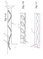
图1-A为本发明的实施例中具有软带式加热器的患者导管的示意侧剖面视图;Figure 1-A is a schematic side sectional view of a patient catheter with a flexible band heater in an embodiment of the present invention;
图1-B为图1-A的可选实施例,其中软带式加热器为螺旋形结构;Fig. 1-B is an optional embodiment of Fig. 1-A, wherein the soft band heater is a spiral structure;
图1-C为图1-A的可选实施例,其中软带式加热器围绕着其纵向轴线卷曲;Figure 1-C is an alternative embodiment of Figure 1-A in which the flexible tape heater is crimped about its longitudinal axis;
图2为软带式加热器的另一个实施例的示意立体图;Fig. 2 is a schematic perspective view of another embodiment of a flexible band heater;
图3为具有浮动加热器实施例的加湿室的示意侧视剖面图;Figure 3 is a schematic side cross-sectional view of a humidification chamber with a floating heater embodiment;
图4-A至图4-D示意性示出了位于加湿室中的浮动加热器可以具有的多个实施例;Figures 4-A to 4-D schematically illustrate various embodiments that a floating heater in a humidification chamber can have;
图4-A是浮动加热器的一个实施例的侧视立体图,圆形浮动片式加热器被固定在浮动塑料支承栅板的下方;Figure 4-A is a side perspective view of one embodiment of a floating heater with a circular floating chip heater secured beneath a floating plastic support grid;
图4-B是浮动加热器的另一个实施例的侧视立体图;Figure 4-B is a side perspective view of another embodiment of a floating heater;
图4-C是浮动的螺旋形软带式加热器的另一个实施例的侧视立体图;Figure 4-C is a side perspective view of another embodiment of a floating spiral flexible tape heater;
图4-D是卷绕成水平螺旋形物的软带式加热器的另一个实施例的俯视图;Figure 4-D is a top view of another embodiment of a flexible tape heater wound into a horizontal spiral;
图5示意性示出了包括多个区域的加湿加热器设备;Figure 5 schematically illustrates a humidification heater device comprising a plurality of zones;
图6-A是患者导管的横截面视图,示出了软带式加热器连接至导管壁;Figure 6-A is a cross-sectional view of a patient catheter showing the flexible band heater attached to the catheter wall;
图6-B是图6-A的连接器实施例的另一个视图,其中连接器松开;Figure 6-B is another view of the connector embodiment of Figure 6-A, with the connector released;
图7示出了定位在浅池中的浮动加热器片,其也漂浮在水体的水表面;Figure 7 shows a floating heater chip positioned in a shallow pool, which also floats on the water surface of the body of water;
图8示出了根据本发明的示范实施例的通过连接器连接至入口导管的电源/控制器;Figure 8 shows a power supply/controller connected to an inlet conduit via a connector according to an exemplary embodiment of the invention;
图9示出了连接至流体发生器的图8的入口导管;Figure 9 shows the inlet conduit of Figure 8 connected to a flow generator;
图10示出了连接至患者接口的根据本发明的示范实施例的患者导管或软管;Figure 10 shows a patient catheter or hose according to an exemplary embodiment of the invention connected to a patient interface;
图11示出了根据本发明的示范实施例的连接至连接器的入口导管,还包括流体发生器连接器接头(cuff);Figure 11 shows an inlet conduit connected to a connector, also including a flow generator connector cuff, according to an exemplary embodiment of the present invention;
图12示出了与连接器分离的图11的入口导管;Figure 12 shows the inlet conduit of Figure 11 separated from the connector;
图13示出了图11的入口导管和连接器的横截面图;Figure 13 shows a cross-sectional view of the inlet conduit and connector of Figure 11;
图14示出了入口导管和连接有接线夹的流体发生器连接器接头的部分的后视立体图;Figure 14 shows a rear perspective view of a portion of an inlet conduit and a flow generator connector fitting with a terminal clip attached;
图15为图14的入口导管、流体发生器连接器接头部分和接线夹的正视立体图;Fig. 15 is a front perspective view of the inlet conduit, fluid generator connector joint portion and terminal clip of Fig. 14;
图16为入口导管和不带接线夹的流体发生器连接器接头部分的顶视立体图;Fig. 16 is a top perspective view of the inlet conduit and the connector portion of the flow generator connector without the clip;
图17为根据本发明的示范实施例的接线夹的立体图;17 is a perspective view of a terminal clip according to an exemplary embodiment of the present invention;
图18为根据本发明的示范实施例的流体发生器连接器接头的连接器插头块的立体图;18 is a perspective view of a connector block of a fluid generator connector sub in accordance with an exemplary embodiment of the present invention;
图19为根据本发明的示范实施例的连接器的立体图;19 is a perspective view of a connector according to an exemplary embodiment of the present invention;
图20为图19的连接器的触头的立体图;Figure 20 is a perspective view of the contacts of the connector of Figure 19;
图21为图20的触头和连接器的横截面图;Figure 21 is a cross-sectional view of the contact and connector of Figure 20;
图22为根据本发明的示范实施例的患者导管或软管的立体图以及面罩接头或连接器的一部分的立体图;22 is a perspective view of a patient conduit or hose and a portion of a mask fitting or connector according to an exemplary embodiment of the invention;
图23为将部分接头移除后的图22的患者导管和面罩接头的横截面图;23 is a cross-sectional view of the patient conduit and mask connector of FIG. 22 with a portion of the connector removed;
图24为图10的患者导管和面罩接头的横截面图;24 is a cross-sectional view of the patient conduit and mask connector of FIG. 10;
图25为根据本发明的示范实施例的面罩接头的连接器插头块的顶视立体图;25 is a top perspective view of a connector plug block of a mask adapter according to an exemplary embodiment of the present invention;
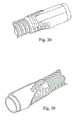
图26为图25的连接器插头块的底视立体图;26 is a bottom perspective view of the connector plug block of FIG. 25;
图27为根据本发明的示范实施例的面罩接头的连接器插头块的顶视立体图,其与患者导管相连且包括面罩接头的印刷电路板;27 is a top perspective view of a connector plug block of a mask connector connected to a patient conduit and including a printed circuit board of the mask connector in accordance with an exemplary embodiment of the present invention;
图28为脱离患者导管的图27的连接器插头块的侧视立体图;28 is a side perspective view of the connector block of FIG. 27 disengaged from the patient conduit;
图29为图27的患者导管和连接器插头块的横截面图;29 is a cross-sectional view of the patient conduit and connector block of FIG. 27;
图30为根据本发明的示范实施例的患者导管和面罩接头的连接器插头块的立体图;30 is a perspective view of a connector block of a patient conduit and mask adapter according to an exemplary embodiment of the present invention;
图31为根据本发明的示范实施例的患者导管和面罩接头的立体图;31 is a perspective view of a patient conduit and mask connector according to an exemplary embodiment of the present invention;
图32为图31的患者导管和面罩接头的横截面图;32 is a cross-sectional view of the patient conduit and mask connector of FIG. 31;
图33为根据本发明的示范实施例的面罩接头的电路的温度传感器和热熔断器的示意视图;33 is a schematic view of a temperature sensor and a thermal fuse of an electrical circuit of a mask joint according to an exemplary embodiment of the present invention;
图34示意性示出了设置在面罩接头的连接器插头块上的面罩接头的电路;Figure 34 schematically illustrates the electrical circuitry of the mask connector disposed on the connector plug block of the mask connector;
图35示意性示出了根据本发明的示范实施例的电源/控制器;Figure 35 schematically shows a power supply/controller according to an exemplary embodiment of the present invention;
图36示意性示出了根据本发明的示范实施例的三根电线加热管;Figure 36 schematically shows a three wire heating tube according to an exemplary embodiment of the present invention;
图37a示意性示出了电源/控制器的电路的示范实施例;Figure 37a schematically shows an exemplary embodiment of a circuit of a power supply/controller;
图37b-1至图37B-4示意性示出了图37a的电路的示范实施例;Figures 37b-1 to 37B-4 schematically illustrate exemplary embodiments of the circuit of Figure 37a;
图38至图40为用于流体发生器接头和/或面罩接头的二次成型抓手部的立体图;38-40 are perspective views of an overmolded grip portion for a fluid generator connector and/or a mask connector;
图41示出了根据本发明的示范实施例的导管;Figure 41 shows a catheter according to an exemplary embodiment of the invention;
图42示出了根据本发明的示范实施例的导管;以及Figure 42 shows a catheter according to an exemplary embodiment of the invention; and
图43示出了根据本发明的示范实施例的患者导管和面罩接头。Figure 43 illustrates a patient conduit and mask connector according to an exemplary embodiment of the present invention.
具体实施方式Detailed ways
软带式加热器Soft Band Heater
图1-A至图1-C示出了在呼吸装置的患者导管4内使用软带式加热器3。患者导管4定位在加湿室1和患者接口例如面罩5之间。患者导管4将气流从加湿室1传送至呼吸装置中的患者面罩5。加湿室1依次接收来自流体发生器20(图5)或吹风机的加压空气。1-A to 1-C illustrate the use of a
患者导管4中的软带式加热器3用于加热患者导管4中的气流。气体的加热能够使由呼吸装置传输的气体获得并维持气体的温度和湿度舒适特征。The
软带式加热器3通过患者导管连接器端2电连接至加热器控制器21(图5)。可以将加热器控制器21并入加湿器或流体发生器20或基极单元22中,或者加热器控制器21是一个独立单元21,例如其供给例如0.1V-24V的DC电压。The
患者导管连接器端2可以通过另一个软带式加热器(图1的左侧局部示出的)连接至加热器控制器21,或者可以通过图6-A和图6-B中示出的连接器23、24连接至患者导管4的导管壁25。连接器可以包括插入式连接器元件23和插口式连接器元件24,它们可以在软带式加热器3和导管壁25之间建立电气通信和/或机械连接。插入式连接器元件23和插口式连接器元件24的位置可以互换。连接器23、24将软带式加热器3锁定在导管壁25的合适位置,但是连接器23、24也可以分离开。连接器23、24可以使用在沿着导管壁25或其周围的任何位置处。The patient
为了减小热损耗和使得随之导致的患者导管4中的水冷凝或“雨滴”最小化,如现有技术中患者导管4可以是绝热的或加热导管。绝热物可以是围绕患者导管4的外管套或包封。外管套和包封可以是泡沫、纤维织物或在双壁导管的情况下外管套和包封可以为空气间隙。In order to reduce heat loss and minimize consequent water condensation or "raindrops" in the
在另一个实施例中,软带式加热器3可以与患者导管4的壁结合,从而对壁提供加热以防止冷凝,然而可选地,患者导管4中的另外一软带式加热器3对气流提供加热。In another embodiment, the
在又一个实施例中,患者导管4通过如下方式形成:将软带式加热器3制成螺旋状并将软带式加热器3的边缘结合起来从而形成患者导管4。In yet another embodiment, the
软带式加热器3应该足够柔软,从而在使用中患者导管4的弯曲不受限制。软带式加热器3的柔性还应该足以使软带式加热器3能够插入患者导管4中和从患者导管4中移除,同时其还足够刚硬从而软带式加热器3能够插入患者导管4中并将其支撑在期望的位置而不会抵靠着壁塌陷或者塌陷至患者导管4的一端。另外,硬度应该足够以使软带式加热器3不会在气流中摆动而产生不想听到的噪声。The
软带式加热器3的薄、扁平和延伸特性提高了与气流的热传导,同时还对气流提供了低阻抗。可以将软带式加热器3放置在患者导管4中以使其具有螺旋结构(图1-B),和/或软带式加热器3可以围绕着一个或多个软带式加热器3轴线卷曲或弯曲。图1-C中示出了纵向轴线卷曲结构。The thin, flat and elongated nature of the
软加热带的可选轮廓或几何结构可以包括:Optional profiles or geometries for soft heating bands may include:
软带式加热器的横截面可以是矩形、椭圆形或任意形状;The cross-section of the soft band heater can be rectangular, oval or any shape;
软带式加热器3的表面可以是粗糙、光滑或凹陷的;和/或The surface of the
软带式加热器3的一个或多个表面可以是波浪状的。One or more surfaces of the
沿着软带式加热器的长度,其厚度和宽度的尺寸可以改变。例如,可以在患者导管4中提供软带式加热器3的较厚部分,以产生提高气流流率的文丘里效应,从而可以沿软带式加热器3的长度通过压力传感器来进行流量检测。Along the length of the flexible tape heater, its thickness and width dimensions may vary. For example, a thicker section of the
上面说明的这些卷曲的、螺旋状和其它结构的使用增大了患者导管4中的软带式加热器3的长度,因此增大了在气流和软带式加热器3的表面之间的用于热传导的有效表面积。另外,可以使用这些结构来提高加湿器1中产生的水蒸汽与气流的涡流混合。The use of these coiled, helical, and other structures described above increases the length of the
还可以使用各种结构,以沿着患者导管4或例如图5中示出的整体装置提供在流量、传声、湿度或温度特性上不同的区域。Various configurations may also be used to provide zones along the
可能期望的是,利用软带式加热器3改进患者导管4的声阻抗特性。例如:It may be desirable to improve the acoustic impedance characteristics of the
白噪音的生成或减少(宽频谱噪音);Generation or reduction of white noise (broad spectrum noise);
对特定声噪声频率成分的衰减或过滤,例如流体发生器结构声噪或空气声噪;和/或Attenuation or filtering of specific acoustic noise frequency components, such as fluid generator structure-borne or airborne noise; and/or
增强患者呼吸声音信号传播穿过患者导管4并传播至基极单元22(图5)以用于监控和诊断。The enhanced patient breathing sound signal propagates through the
利用软带式加热器3改进声阻抗特性可以通过选择构成软带式加热器3的材料和患者导管4中的软带式加热器3的上述构造来实现,以及另外如图1-A至图1-C中示出的。Improvement of the acoustic impedance characteristics by utilizing the
图2示出了软带式加热器3的一个实施例,其中通过加热元件6来加热。FIG. 2 shows an embodiment of a
在一个实施例中,加热元件6通过对诸如KAPTON
然后将另一层衬底材料铺设在具有加热元件的底衬底上,并将两层衬底材料黏合或熔合在一起以封装加热元件。在www.minco.com上说明的由美国明尼阿波利斯的Minco制造的柔性加热器类型的ThermofoilTM系列是商业上可以买到的条式加热器的示例,可以将其改造以用于本发明。Another layer of substrate material is then laid over the base substrate with the heating element, and the two layers of substrate material are bonded or fused together to encapsulate the heating element. The ThermofoilTM series of flexible heaters of the type manufactured by Minco of Minneapolis, USA illustrated atwww.minco.com are examples of commercially available strip heaters that can be adapted for use in this invention.
用于制造软带式加热器3的可选实施例是使用诸如双硅辊层压机的层压机以将呈金属丝或金属带形式的加热元件6封装在两个聚碳酸酯膜中。所形成的带的尺寸例如可以在1mm至10mm宽且0.1mm至1mm厚的范围内。在患者导管4中可使用大约0.2mm至0.5mm厚和大约5mm宽的尺寸。An alternative embodiment for manufacturing the
加热元件6金属丝或金属带可以具有任何合适的横截面,例如圆形、细长形或矩形。加热元件6例如可以由电阻性导体构成。The
加热元件6在层压膜之间的布置可以是任何能提高软带式加热器3到周围媒介(为气体或液体)的热传导的有序或无序的布置。加热元件6还可以对于阻抗具有正导热系数(PTC),从而随着温度朝着期望的温度增加而减小加热。The arrangement of the
可选择地,加热元件6可以具有负导热系数(NTC),以允许感测加热元件6的温度或周围媒介的温度。Alternatively, the
在其它实施例中,在软带式加热器3中可以具有多个加热元件电路。该多个加热元件可以串联或并联连接。在软带式加热器3中使用这些多个加热电路使得能够施加呼吸装置操作中所需要的附加加热。In other embodiments, there may be multiple heating element circuits in the
在其它实施例中,层压膜可以是聚酯、聚丙烯或任何合适且允许的适于呼吸内科(respiratory medicine)使用的物质。可选择地,可以使用多个层压膜以生成具有期望特性的复合带,同时保持对于呼吸内科使用的外膜的期望兼容性。在这些多个层的每个之间还可以存在其它导体,例如以便形成多个加热电路,诸如允许沿着带式加热器的长度具有多个加热区。In other embodiments, the laminating film may be polyester, polypropylene, or any suitable and permitted substance suitable for use in respiratory medicine. Alternatively, multiple laminated films may be used to create a composite tape with desired properties while maintaining desired compatibility with outer membranes used in respiratory medicine. There may also be other conductors between each of these multiple layers, for example to form multiple heating circuits, such as to allow multiple heating zones along the length of the tape heater.
在另一个实施例中,在两层聚碳酸酯膜之间可以包括空气温度用的传感器7,诸如热电偶、铂电阻温度计或具有附带信号线9的热敏电阻。传感器头可以是扁平的,厚度小于约2mm,且可以小于1mm。诸如表面贴装电路部件的其它电路部件可以结合在衬底膜上进而并入软带中以用于感测和/或控制。另外,在如上所述的由衬底膜分隔的多层中可以有加热元件6和其它的电路部件。In another embodiment, a
对于软带式加热器3来说,其它电路部件都具有共同的物理特征,即它们的尺寸足够小,以使它们能够容纳在软带式加热器3的整体轮廓中且与加热元件6搭配。For the
在可选实施例中,软带可以不具有加热器元件6,取而代之的是结合一个或多个用于感测和控制的其它电路元件。因此,呼吸装置可以包含两个或多个软带,一个或多个软带承担加热功能,而一个或多个软带承担感测和/或控制功能。In an alternative embodiment, the flexible strip may not have the
可以使用的其它电路部件的范围通过示例在下面示出:A range of other circuit components that may be used are shown below by way of example:
相对和绝对湿度传感器7a;relative and absolute humidity sensor 7a;
具有正导热系数(PTC)或负导热系数(NTC)的呈热敏电阻形式的温度传感器7a或具有可变PTC特性的温度传感器7a可以是加热元件6固有的,从而软带式加热器3是自限制的。A temperature sensor 7a in the form of a thermistor with a positive thermal conductivity (PTC) or a negative thermal conductivity (NTC) or a temperature sensor 7a with a variable PTC characteristic can be intrinsic to the
可以使用热电偶、铂电阻测温计等来产生用于控制和监控的实际温度值信号。Thermocouples, platinum resistance thermometers, etc. can be used to generate actual temperature value signals for control and monitoring.
气体的流向感测可以通过使用至少两个独立控制的加热区段来实现,这两个独立控制的加热区段沿着软带式加热器间隔开,每个加热区段包括温度传感器(例如,热敏电阻)。这两个或多个加热区段受控制,且感测的温度用以检测气流的方向。Flow direction sensing of the gas can be achieved by using at least two independently controlled heating sections spaced along the flexible band heater, each heating section including a temperature sensor (e.g., thermistor). The two or more heating zones are controlled, and the sensed temperature is used to detect the direction of airflow.
用于气流感测7a的热线风速测定;Hot wire anemometer for airflow sensing 7a;
环境压力感测7a,例如吸气压力对呼气压力;Ambient pressure sensing 7a, eg inspiratory pressure vs expiratory pressure;
利用传感器7a的输出(例如温度输出)的控制器7b,其用于控制例如晶体管,该晶体管调节施加至加热元件6的加热元件用的电流;a controller 7b utilizing the output of the sensor 7a, such as a temperature output, for controlling, for example, a transistor that regulates the current applied to the
识别-通信-存储芯片8,其能够实现软带式加热器3到基极单元22、呼吸装置中的其它加热器和部件的操作参数的识别和通信。例如,软带式加热器3可以对自己进行通信,以及对连接至呼吸装置(例如,患者面罩5类型或患者导管4类型或主动通气系统)的其它部件进行检测和报告。由此由软带式加热器3收集的信息然后可以发送至基极单元22。识别通信存储系统可以部分地包括射频识别芯片(RFID)以存储加热器6和传感器7的识别和操作参数。基极单元22可以具有与RFID芯片通信的能力,并相应地调节其操作。在标题为“用于面罩和通气部件的识别系统和方法”的澳大利亚专利申请No.2005907200中已公开了这种系统,其全部内容通过引用合并在此。通信还可以用于控制主动通气系统。Identification-communication-
通过微型天线和接收器来拟定电磁通信,例如“蓝牙”。例如,用于发送和接收信息的天线可以定位在软带式加热器3中、患者导管4的壁中,或者主动通气系统中,或者图5中示出的呼吸装置的其它部件中。在另一个实施例中,天线可以是由软带式加热器3或患者导管4的长度所允许的大小。Electromagnetic communication, such as "Bluetooth", is envisioned via tiny antennas and receivers. For example, antennas for sending and receiving information may be located in the
软带式加热器的电力供给可以采用与上面说明的电磁通信相同的方式。在本实施例中,天线或感测线圈将适于电力传输。Power supply to the flexible tape heater can be done in the same way as the electromagnetic communication described above. In this embodiment, an antenna or sensing coil would be suitable for power transfer.
这些部件可以沿软带式加热器3定位在对于它们的功能合适的任何地方。例如,热电偶可以定位在软带式加热器3与患者面罩5相邻的一端上,以能够基于传送至患者面罩5的气体温度来实现闭环温度控制。These components may be positioned anywhere along the
在可选实施例中,温度传感器可以定位在患者面罩5中或者其附近,但是与软带式加热器3分离开。然而,温度传感器可以以上述方式之一与软带式加热器3连通,以实现传送至患者的气体的温度的闭环控制。In an alternative embodiment, the temperature sensor may be located in or near the
软带式加热器3还可以包括微管26(图2),以允许远离流体发生器和/或加湿室1的远程感测。例如,微管可以提供压力、噪声/通气和/或心脏的信号感测。例如,微管可以连接至软带式加热器3的侧部,且以上述方式之一连接回流体发生器20。微管26的使用提供了避免在患者导管4和呼吸装置中的其它区域中的流动噪音的好处。The
上面说明的感测和控制方法允许使用闭环控制来改进到患者面罩5的气体传送,从而使气体处于期望的温度和湿度。可替换地,可以使用简单的开环系统,其中用于加热元件的激励电压或电流例如可以是从0.1V至24V的直流或例如可以是0.1W至50W的等效交流电力。感测和控制还可以根据供给的压力的大小来控制主动通气系统的有意气体泄露的水平。例如,随着呼吸器压力的增大,可以控制主动通气系统以将其有意的泄露的水平减小至可接受的水平。The sensing and control method described above allows closed loop control to be used to improve gas delivery to the
另外,传感器7a可以用于应允或者统计数据采集。In addition, the sensor 7a can be used for accreditation or statistical data collection.
另外,这里说明的加热器和/或感测/控制系统的不同部件可以在呼吸装置中作为独立部件使用,而不使用加湿器,这种布置涵盖在本发明的范围之内。Additionally, the various components of the heater and/or sensing/control system described herein could be used as stand-alone components in a respiratory apparatus without the use of a humidifier and such arrangements are within the scope of the present invention.
由此,描述的软带式加热器3可以容易地从患者导管4移除,以能够实现清洁、维护或更换。通过将感测和控制部件7简单地并入软带式加热器3中,软带式加热器3还提供了有效率的加热。Thereby, the
浮动加热器floating heater
图3中示出了利用浮动加热器12的加湿器设备。浮动加热器12漂浮在加湿室水桶1中的水体13上,从而使浮动加热器12的主要部分浸入,但是仍邻近水表面14以便加热靠近表面14的一部分水。A humidifier arrangement utilizing a floating
浮动加热器12可以包括具有与上面参考图1-A至图1-C和图2说明的软带式加热器相似的结构的一段软带式加热器。加热器的位于从流体发生器20引出的入口导管10中的一端可以设置有连接器11,该连接器11能够将浮动加热器12与软带式加热器相连,而软带式加热器连接至呼吸装置的基极单元22(图5)。浮动加热器12通过上游端连接器11获得电供给。还通过上游端连接器11接收传到浮动加热器12或来自浮动加热器12的任何感测或控制信号。The floating
浮动加热器的位于通向患者接口的患者导管4中的下游端2可以具有另一个连接器,该连接器用于提供电力以及与位于患者导管4中的软带式加热器的其他部分提供任何通信(见图1-A、图1-B、图1-C和图2)。The
加热器12可以适于通过加热器自身的自然浮力而漂浮(通过表面张力效应),或者可以以不管水位变化而将加热器保持在靠近水表面的方式被支撑。The
图4-A至图4-E示出了多个实施例,其中浮动加热器3、12、16、17可以位于加湿室1中。每个实施例中的浮动加热器3、12、16、17或者由前面说明的软带式加热器类型形成,或者由板形的软带式加热器3、浮动片式加热器16形成。FIGS. 4-A to 4-E show embodiments in which floating
浮动软带式加热器3和浮动片式加热器16的结构和使用与上面说明的软带式加热器3相同,除了它们应用在水上之外。这具有显著的优点:这两种应用下的加热器对于气体或水浸入是坚固耐用的,因为无论是无意地通过倾斜该装置使水体体积增加或减小时,或者有意地保持加湿器1的气体中的水蒸汽的温度时,在呼吸装置操作期间浮动软带式加热器3或浮动片式加热器16可以部分浸入水中。The construction and use of the floating
图4-A示出了圆形浮动片式加热器16,该加热器被固定在由例如浮力塑料材料制成的浮动支承栅板或板15下方。支承栅板15为浮动片式加热器16提供了浮动定位机构,以将加热器元件间隔在水表面14的正下方,从而与水充分接触以引起汽化。在图7中示出的可选实施例中,浮动加热器板定位在浅池中,并且漂浮在水体13的水表面14。在该实施例中,浮动片式加热器包括至少一个开口,以允许水填充浅池以漫过加热器板16。浅池中的小容量的水可以快速被加热以产生蒸汽。Figure 4-A shows a circular floating sheet heater 16 secured below a floating support grid or plate 15 made of, for example, buoyant plastic material. The support grid 15 provides a floating positioning mechanism for the floating fin heater 16 to space the heater elements just below the
图4-B示出了另一个实施例,其中板结构为以规则或不规则方式成波浪状或带凹陷的。波状物和/或凹陷提供了凹部,这些凹部允许水窝积聚在浮动板16的上表面上。在本实施例中,浮动片式加热器16本身地是有浮力的,因此其不需要支承栅板或其它浮力装置就能够漂浮。Figure 4-B shows another embodiment where the plate structure is corrugated or dimpled in a regular or irregular manner. The corrugations and/or dimples provide recesses that allow pockets of water to accumulate on the upper surface of the floating plate 16 . In this embodiment, the floating fin heater 16 is inherently buoyant so that it floats without the need for support grids or other buoyancy devices.
图4-C示出了卷绕为螺旋结构的软带式加热器3。在该实施例中,浮动的螺旋形软带式加热器17可以本能地漂浮以使浮动的螺旋形软带式加热器17的主要部分浸入水体13。在另一个实施例中,软带式加热器3可以卷绕成水平螺旋形物,如图4-D。对于图4-C和图4-D的实施例,可以使用图4-A中使用的支承栅板15来定位软带式加热器3、12、17。Fig. 4-C shows the
浮动加热器3、12、16、17的前述实施例描述了多个限定的结构,然而在使用中浮动加热器可以采用限定的或未限定的结构的组合。例如,结合图4-C和图4-D的以螺线形持续的长螺旋结构。The foregoing embodiments of the floating
在上面的浮动加热器3、12、16、17的实施例中,加热器向加热器周围的水提供了有效的热传递。另外,将临近水表面的水加热以实现汽化,而不是从底部向上对整个水体进行加热,在将加热器定位在水体13底部的情况下是从底部向上对整个水体进行加热。In the floating
另外,软带式加热器结构可以是螺旋的,或者以其它方式形成为其部分浸入在水体13中,从而其不仅能加热靠近空气的水还能加热靠近水的空气,以产生分层加热区,进而提高水的吸收以用于湿化。因此,浮动加热器3、12、16、17在生成水蒸气方面更加动力有效,并且在装置的启动时能够更有效地快速达到用于湿化的期望的水表面温度。Additionally, the flexible tape heater structure may be helical, or otherwise formed such that it is partially submerged in the body of
多区加热multi-zone heating
图5示出了使用了三个加热器的呼吸装置,这三个加热器的整体结构和使用与上述软带式加热器3和浮动片式加热器12、16、17相同。FIG. 5 shows a breathing apparatus using three heaters. The overall structure and usage of these three heaters are the same as those of the
这些加热器可以包括多个加热电路,从而可以独立地操作三个加热区中的每个。These heaters can include multiple heating circuits so that each of the three heating zones can be operated independently.
流体发生器20或吹风机从环境温度供给来供给气体,环境温度供给可以是室内空气,或者增加诸如氧气的特定气体供给或用特定气体供给替代替。将预加热器18定位在通向加湿器1的吹风机联结器10中。吹风机联结器可以是刚性的、柔性的或者是对于吹风机联结器10的操作或定位在吹风机联结器中的预加热器18的操作所需的导管。将预加热器18连接至基极单元22的控制器/电源21,该控制器/电源21用于供给电力并与预加热器18的任何感测或控制部件7通信,如软带式加热器3的实施例。预加热器18在吹风机导管连接器端11连接至加湿室1的浮动加热器12、16、17。浮动加热器12、16、17使用通过预加热器18接收控制器/电源21的电力供给和与浮动加热器12、16、17的感测或控制部件7进行任何通信。The
可替换地,浮动加热器12、16、17还可以以上述图6-A和图6-B中描述的患者导管4的方式通过吹风机联结器10的壁与控制器/电源21相连。Alternatively, the floating
后加热器19定位在患者导管4中。患者导管连接器端2为后加热器19的感测和控制部件7提供控制器/电源21的电力供给和通信。患者导管连接器端2可以通过图5中示出的浮动加热器12、16、17或者通过图6-A和图6-B中示出的导管壁25连接至控制器/电源21,然后通过加湿室1连接至基极单元22中的控制器/电源21。An
在可选实施例中,一个或多个加热器可以不是上面说明的类型,而是其它合适的加热元件。例如,预加热器18可以形成为简单的线式加热器或者其它传统类型的加热器,而不是这里说明的类型的软带式加热器。In alternative embodiments, one or more heaters may be other than the types described above, but other suitable heating elements. For example, the pre-heater 18 could be formed as a simple wire heater or other conventional type of heater rather than a flexible tape heater of the type illustrated here.
使用这种布置可以提供下面的优点:Using this arrangement provides the following advantages:
位于吹风机联结器10、加湿室1和患者导管4内部的单个互连加热器系统;a single interconnected heater system located inside the
可以将整个加热器、传感器和控制系统移除,仅用于清洁、维护或更换;The entire heater, sensor and control system can be removed for cleaning, maintenance or replacement only;
互连有助于对传输至患者的空气的温度和湿度进行高度闭环控制;Interconnects allow for a high degree of closed-loop control over the temperature and humidity of the air delivered to the patient;
在患者导管4的不同部分处感测温度和湿度的能力,以能够在患者导管4中的不同部分控制冷凝;The ability to sense temperature and humidity at different parts of the
加热器和/或感测/控制系统的不同部件可以组合地或单独地在传统的加湿器中使用。例如,柔性加热带3还可以用于与具有加热基板的传统加湿器一起加热患者导管4。可替换地,如上所述,浮动加热器12、16、17或软带式加热器3可以用于对加湿室1中的水体13和患者导管4的加热壁或绝热壁进行加热;和/或The different components of the heater and/or sensing/control system may be used in a conventional humidifier in combination or individually. For example, the
将多个加热器并联和串联安装在呼吸装置的任何位置的能力。例如,这可以允许当水体13需要时间来达到期望的温度时在呼吸装置操作初期的“过热”。利用多个加热器电路对空气的临时额外加热将提高空气汲取较冷水的能力。这可以响应于水体14中的水的温度来控制或调整(profile),以提供合适的湿度水平。The ability to install multiple heaters in parallel and in series anywhere on the breathing apparatus. For example, this may allow for "overheating" early in breathing apparatus operation when the body of
对于呼吸装置,三个加热器的放置以及它们使用的时间和顺序通过允许独立的交错工作来管理气体温度和湿度舒适特征:For breathing apparatus, the placement of the three heaters and the timing and sequence of their use manage gas temperature and humidity by allowing independent interleaved comfort characteristics:
加热具有低绝对湿度的环境气体;Heating ambient gases with low absolute humidity;
使水汽化;和/或vaporize water; and/or
加热具有增大的绝对湿度(经过加湿室1之后)的气体。Gas with increased absolute humidity (after passing through humidification chamber 1 ) is heated.
使用下面的示例示出了在这里公开的示范实施例操作的优点。The advantages of operation of the exemplary embodiments disclosed herein are illustrated using the following example.
患者呼吸气体需要注意温度和湿度舒适特征,特别是在冬天和很冷的气候下。在实施例中,系统冷启动的目的是,起初快速传输暖气体,然后随着加湿器变暖随时间增大湿度。这种方法允许在任何低湿度呼吸辅助的不利征兆发生之前,让患者接收舒适的暖空气,紧接着增加相对湿度。Patient breathing gases require attention to temperature and humidity comfort characteristics, especially in winter and very cold climates. In an embodiment, the purpose of the cold start of the system is to deliver warm gas quickly initially, then increase the humidity over time as the humidifier warms. This approach allows the patient to receive comfortably warm air followed by an increase in relative humidity before any adverse signs of low humidity respiratory assistance occur.
对于在寒冷气候中的冷启动,三个加热器系统因而可以以下面的方式操作。首先,通过使用位于吹风机联结器10的预加热器18暖化来自流体发生器20的冷环境温度气体,或许需要患者导管4中的后加热器19的辅助。这初始地将暖的干燥的空气提供给患者。For cold starts in cold climates, the three heater system can thus be operated in the following manner. First, the cold ambient temperature gas from the
随着暖气流开始从加湿室1中的未加热水中吸收相当量的水蒸气,患者导管4中的后加热器19开始或增大其加热以防止患者导管4中的“雨滴”冷凝。利用预加热器18对空气初始暖化具有立即开始一定程度的湿化的优点,作为一个简单的“过渡”(pass over)操作,而浮动加热器12、16、17仍然对水进行暖化。在简单的“过渡”操作中用于汽化的热由加热的空气来提供。As the warm air flow begins to absorb a substantial amount of water vapor from the unheated water in the
随着浮动加热器12、16、17开始暖化水表面并快速地增加穿过加湿室的空气的绝对湿度,以达到期望的湿化水平,患者导管4中的后加热器19将调整其加热,以通过防止患者导管4中的冷凝来维持绝对湿度。后加热器19还可以用作维持患者导管4中的期望的气体温度。预加热器18可以具有基于加湿室1中的水体13的加热水平的加热廓线(heating profile),加热廓线是在一段时间内气流的加热比率,可以通过改变供给至预加热器18的电力或预加热器18的结构配置来提供加热廓线。应该相信的是,与加热水相反,通过控制空气温度可以存在更有效的湿度控制。The
该示范实施例的另一个优点在于,在湿化启动时其允许更少的电力消耗,从而呼吸装置能够通过直流电源或便携式电源来操作。另外,当将两个或多个加热器并联时,仍然可以获得满意的操作,其中每次操作一个加热器,但是在两个或多个加热器之间进行循环操作。Another advantage of this exemplary embodiment is that it allows for less power consumption when humidification is activated so that the breathing apparatus can be operated from a DC power supply or a portable power supply. Additionally, satisfactory operation can still be obtained when two or more heaters are connected in parallel, operating one heater at a time, but cycling between the two or more heaters.
入口导管连接Inlet Conduit Connection
参考图8,电源/控制器21可以通过连接器52连接至入口导管/吹风机联结器10。连接器52具有连接至电源/控制器21的第一连接器端52a和连接至入口导管10的第二连接器端52b。入口导管10具有流体发生器接头或连接器54。流体发生器接头54具有端54a,该端被构造为与流体发生器20连接。流体发生器接头54还具有二次成型抓手或接头54b,该抓手或接头限定了接线夹54c。Referring to FIG. 8 , the power supply/
如图9中所示,入口导管10通过流体发生器接头54连接至流体发生器20。连接器52在接线夹54c处连接至流体发生器接头54。尽管图9中未示出,但是应该理解的是,连接器52的第一端52a连接至电源/控制器21。电源/控制器21通过连接器52将电流和信号提供至流体发生器接头54。As shown in FIG. 9 ,
患者导管连接patient catheter connection
如图10所示,患者导管/空气传输软管4通过面罩连接器或接头56连接至患者接口5。患者导管4包括管4a和螺旋肋4b,管4a例如由热塑性弹性体制成,螺旋肋4b由极低密度聚乙烯制成。电线4c、4d、4e被支撑在螺旋肋4b中以便与管4a的外表面接触。电线4c、4d、4e可以用于加热管4a,并将信号传递至电源/控制器21和传递来自电源/控制器21的信号。应该理解的是,入口导管10可以具有与患者导管4相似的结构,包括管10a、螺旋肋10b和由管上的螺旋肋支撑的电线10c-10e。As shown in FIG. 10 , the patient conduit/
入口导管和流体发生器连接器接头Inlet Conduit and Fluid Generator Connector Fittings
参考图11,流体发生器接头54包括连接器插头块54a。抓手或接头54b二次成型在连接器插头块54a上以将连接器插头块54a连接至入口导管10。二次成型抓手或接头54b包括位于二次成型抓手或接头54b的外表面上的诸如用户手指用的凹槽的抓手特征54d,以提供在连接器接头54上的更好的抓取。Referring to Fig. 11, the
如图8、图12和图13所示,流体发生器接头54包括接线夹54c,该接线夹54c接纳连接器52的第二连接器端52b。如图13中所示,接线夹54c包括肋54n,该肋被接纳在连接器52的引入部52e中。该肋54n接合引入部52e以将连接器52固定至接线夹54c。As shown in FIGS. 8 , 12 and 13 , the
接线夹54c还包括用于定位入口导管10的电线10c、10d、10e的齿54e。电线10c、10d、10e被放置在热塑性弹性体管10a的外表面上,并通过螺旋肋10b保持在外表面上的适当位置。The
在连接器插头块54a中设置沟槽54j,以允许二次成型材料54b流动并结合至管10a的内部,从而建立连接器插头块54a和入口导管10之间的连接。连接器插头块54、管10a和二次成型材料54b可以由以化学方法结合的材料形成。
参考图14,接线夹54c包括接线夹销54h,该接线夹销被接纳在接线夹铰合部54f的铰接槽54g中。接线夹铰合部54f设置在连接器插头块54a上。接线夹54c搭扣配合进接线夹铰合部54f中,以确保齿54e与入口导管10的电线10c、10d、10e之间的连接。如图15中所示,可以在将入口导管10连接至连接器插头块54a之前将接线夹54c连接至连接器插头块54a。将接线夹销54h连接至铰接槽54g中,且将接线夹54c向前倾斜或者旋转。然后,将入口导管10连接至连接器插头块54a,然后向后旋转或枢转接线夹54c以使齿54e接触入口导管10的电线10c、10d、10e。如图16和图17中示出的,连接器插头块54a包括入口导管10的螺旋肋10b用的导向槽54p,以定位电线10c、10d和10e使其与齿54e接触。Referring to FIG. 14, the
参考图17,接线夹54c包括拱形部54k,当将接线夹54c插入接线夹铰合部54f时,该拱形部54k与导向槽54p(图16)限定了一沟槽。在连接器插头块54a中设置槽54i(图18)以接纳螺旋肋10b和入口导管10的电线10c、10d、10e。槽54i具有光滑表面和宽的接触区域,以防止或将对电线10c、10d、10e的损害最小化。还如图18中所示,邻近沟槽54j设置有空腔54m,以在将抓手或接头54b二次成型至连接器插头块54a期间允许有些空气经过。Referring to FIG. 17, the
参考图19至图21,第二连接器端52b具有抓手特征52c,以允许更容易地抓住第二连接器端52b。在第二连接器端52b中还形成有应变消除特征52d(strain relief feature)以增加柔韧性。还可以在连接器52的第一连接器端52a上设置抓手和应变消除特征。Referring to FIGS. 19-21 , the
设置触头52f、52g、52h用于从入口导管10的电线10c、10d、10e发送和接收信号。尽管示出的入口导管10包括三根电线,而示出的接线夹54c具有用于接纳第二连接器端52a的三个触头的三个端子,但是应该理解的是,可以使用任意数量的电线、端子和触头,以用于传输和接收从电源/控制器21至入口导管10传输和接收信号。
患者导管和面罩连接器接头Patient Tubing and Mask Connector Fittings
参考图22至图34,设置了面罩连接器或接头56,用于将患者导管/空气传输软管4连接至患者接口5。面罩连接器或接头56包括连接器插头块56a,该连接器插头块56a通过二次成型抓手或接头56b连接至患者导管4。连接器插头块56a、管4a和二次成型接头56b可以由以化学方法结合的材料形成。Referring to FIGS. 22-34 , a mask connector or fitting 56 is provided for connecting the patient conduit/
如图24中所示,将连接器插头块56a连接至患者接口5的入口5a。该入口5a例如可以是面罩的旋转弯管。
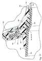
在连接器插头块56a的外表面周围设置印刷电路板(PCB)56c。将患者导管4的电线4c、4d、4e连接至PCB 56c。如图25、图27和图28所示,连接器插头块56a包括用于接合PCB 56c中的孔或开口56u的钩扣或销56i。由此PCB 56c包绕在连接器插头块56a的外表面并且保持在适当位置。热熔断器56d和温度传感器56e例如热敏电阻设置在PCB 56c上。如图23和图26所示,在连接器插头块56a的外表面中设置一个或多个窗口56j,热熔断器56d和温度传感器56e设置在窗口56j中。窗口56j被PCB 56c覆盖,如图24中所示。如下面详细说明的,PCB 56c包括加热器轨道,通过将PCB 56c暴露在沿着窗口56j的气流中来冷却该加热器轨道。A printed circuit board (PCB) 56c is provided around the outer surface of the
如图22至图26所示,将螺旋肋56f设置在连接器插头块56a的外表面上,以定位患者导管4。如图25所示,连接器插头块56a的外表面包括阶梯凹部56h,以允许二次成型材料流动并结合至柔性PCB 56c的下侧。如图29中所示,连接器插头块56a还包括沟槽56t,以允许二次成型材料与患者导管4的管4a的内部结合在一起。返回参考图25,邻近沟槽56t设置有空腔56g,以允许在二次成型期间空气漏出。还如图28和图29所示,连接器插头块56a的端部包括轮廓56n,该轮廓56n将聚集残渣的容量以及在确有残渣聚集时需要清除残渣的容量减到最少。轮廓56n的端部还使二次成型材料的流动阻抗最小化。As shown in FIGS. 22 to 26 ,
如图25和图27所示,在螺旋肋56f和端沟槽56t之间设置注入沟槽56m,以允许二次成型材料将管4a结合至连接器插头块56a。如图30所示出,管4a拧(twist)在连接器插头块56a上,且患者导管4的电线4c、4d、4e在示出的56p处焊接至柔性PCB 56c。As shown in Figures 25 and 27, an
参考图31,二次成型抓手或接头56b可以包括成型抓手特征56q以提高面罩接头或连接器56的抓取能力,诸如容纳用户手指的凹槽。连接器插头块56a可以由刚性聚合体形成,而二次成型抓手或接头56可以由热塑性弹性体形成。如图32中所示,连接器插头块56a可以具有标准22mmISO锥度,用于连接至患者接口。还如图32中所示,二次成型材料可以在热熔断器56d的区域中在56s处切掉(blank off)。Referring to FIG. 31 , the overmolded grip or joint 56b may include molded grip features 56q to improve the gripping ability of the mask joint or
参考图33和图34,柔性PCB 56c上的电路包括热熔断器或开关56d和热传感器56e。电线之一例如4c可以用作温度感测线以将温度信号发送至电源/控制器21。其它的电线例如4d、4e可以用作加热器线以加热患者导管4的管4a。如果温度超过某一值,热熔断器56d被构造为切断到加热器电线4d、4e的电流。33 and 34, the circuitry on the
柔性PCB 56c和温度传感器56e和热熔断器56d应该设置在连接器插头块56a上,连接器插头块56a尽可能地靠近患者接口5的入口5a和通过患者导管4的空气通路。面罩连接器或接头56还可以形成得尽可能小,以允许其与现有的呼吸装置一起使用。二次成型抓手或接头56b的使用对于将患者导管4固定在连接器插头块56a上并将柔性PCB 56c(包括温度传感器56e和热熔断器56e)固定在适当位置也是有用的。二次成型材料的使用还有助于减小或消除任何细菌可能生长的位置。The
这里所述的面罩连接器或接头56是由生物兼容性材料形成的。连接器插头块56a还包括端56r(图32),该端包括标准22mm插口式ISO锥度以与现有的患者接口一起使用。二次成型材料的使用还简化了制造,并提高了面罩连接器或接头的可靠性。The mask connector or joint 56 described herein is formed from a biocompatible material. The
电源/控制器power supply/controller
参考图35,电源/控制器21包括开关式电源21a、开关21b、控制单元21c和多个LED 21d。电源/控制器21具有AC电源输入21e、DC电源输出21f和到流体发生器20的旁路AC电源引线21g。AC电源输入21e可以例如是110-240V AC通用输入。开关21b可以是与加热器元件串联的MOSFET开关并且受控制单元21c的控制。DC电源输出21f例如可以是500mA稳压5V DC,或者1.3A、24V DC输出。在24V输出时,功率输出为30W。Referring to FIG. 35, the power supply/
电源输入21e连接至开关式电源21a,而旁路21g连接至流体发生器20的AC电源插槽。电源/控制器21被构造为将电力提供至入口导管10,调整在患者接口5处的预设温度水平以及充当ON/OFF控制。The power input 21e is connected to the switched mode power supply 21a and the bypass 21g is connected to the AC power socket of the
控制单元21c为闭环温度控制系统。定位在面罩接头56中的温度传感器56e通过患者导管4的电线4c提供反馈信号返回至控制单元21c。然而应该理解的是,控制可以不依赖于温度信号的反馈。控制单元21c反而可以被构造为提供预定量的电力至输出21f而不依赖或取决于温度传感器信号。The control unit 21c is a closed-loop temperature control system. A
DC电源输出21f将电力提供至入口导管10,而开关21b与电源输出21f串联设置并且受控制单元21c的控制。电力调整是基于ON/OFF控制技术来进行的。功率调整具有大约95%-99%比率的固定占空比。OFF周期用于温度感测,例如OFF周期为大约1%-5%比率。A DC power output 21f provides power to the
LED 21d可以包括绿LED以指示电源接通且正供给至入口导管10。可以设置黄色LED以指示电源输出21f接通但是未提供至入口导管10。可以设置红色LED以指示故障。还可以设置其它LED用于指示和/或控制温度。电源/控制器可以设置手动操作按钮(未示出),以允许通过患者或临床医生响应于LED的温度指示来控制温度。LED 21d may comprise a green LED to indicate that power is on and being supplied to
控制单元21c被构造为产生用于电源输出21f的固定的电力切换频率和占空比,以加热入口导管10。控制单元21c还被构造为经由由温度传感器56通过电线4c发送的信号来感测温度。基于感测出的温度,控制单元21c被构造为当环境温度改变时将温度调节为预设温度。控制单元21c被进一步构造为当电源控制/供给21关闭时记录预设温度。The control unit 21c is configured to generate a fixed power switching frequency and duty cycle for the power supply output 21f to heat the
当检测到故障时,控制单元21c还可以锁存故障状态,并通过再循环电力来清除故障。如果出现故障,故障检测电路锁定进入到故障状况以将故障信号发送至驱动器块(图37a),故障将继续直到电力被再次接通和切断。控制单元21c可以被构造为检测故障,故障包括电线4c-4e和10c-10e中的任何中断,流体发生器接头54和/或面罩接头56中的任何电弧放电和/或接触不良。控制单元21c还可以检测低压。When a fault is detected, the control unit 21c can also latch the fault state and clear the fault by recycling power. If a fault occurs, the fault detection circuit latches into a fault condition to send a fault signal to the driver block (Fig. 37a) and the fault will continue until power is switched on and off again. The control unit 21c may be configured to detect faults including any interruptions in the
当检测到故障时,控制单元21c将电源输出21f保持在OFF状态,且电源输出21f维持在OFF状态直到电力再循环且故障状态被清除为止。When a fault is detected, the control unit 21c keeps the power output 21f in the OFF state, and the power output 21f is maintained in the OFF state until power is recirculated and the fault state is cleared.
电源/控制器21的状态可以通过LED 21d指示。The status of the power supply/
如示出的,例如在图5和图8中,电源/控制器21可以与流体发生器20和加湿器分离。在流体发生器20和加湿器之间没有信息交换,且闭环控制不包括基于例如气流速率、湿度水平和加湿器出口温度的控制。但是,应该理解的是,信息例如可以通过感测电线4c来交换。上述控制防止了在患者导管4中的“雨滴”,并将湿化的空气传输至患者接口5。As shown, for example in Figures 5 and 8, the power supply/
应该理解的是,电源/控制器21可以与流体发生器或加湿器控制系统集成在一起。可以将关于流体发生器的操作、加湿器和环境空气的信息提供至集成的电源/控制器。通过将电源/控制器与流体发生器20或加湿器集成在一起,系统更能够将患者接口5处的温度、湿度水平和“雨滴”控制在更宽的环境温度和湿度范围。It should be understood that the power supply/
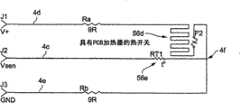
参考图36,示出了根据本发明的示范实施例的三根电线加热管或导管。电线4d、4e例如可以由直径为0.23mm的25m长的电线形成,例如可以由铜形成。感测电线4c可以在连接点4f处连接至加热电线4d、4e,该连接点4f大约处于形成电线4d、4e的电线的中间并将电线分为两个电阻Ra、Rb。例如在20℃-26℃时总电阻Ra+Rb可以等于大约15Ω-20Ω,例如在大约23℃时其大约为18Ω。总电阻Ra+Rb大约为18Ω,而当利用24V DC电源以大约30W的功率将绕线电阻加热到约33℃时,总电阻Ra+Rb大约为21Ω。如上所述,例如,DC电压V+可以以大约95%-99%的占空比通过J1和J3供给。在电流流过电线4d和4e期间电阻Ra、Rb生成热以加热导管4。在1%-5%的OFF周期期间,可以确定感测电压Vsen。在OFF周期期间,控制单元21c激活开关21b,以将系统切换至感测状态,且J1的感测电流经过电阻Ra和温度传感器56e的电阻RT1流回至J2。温度传感器56e的电阻RT1可以大约是1kΩ-50kΩ,而电阻Rb可以是Ra+Rb的大约一半,或者大约为5Ω-15Ω,例如大约10Ω,因此可以忽略Rb。Referring to Figure 36, there is shown a three wire heated tube or conduit in accordance with an exemplary embodiment of the present invention. The
尽管感测电线4c公开为连接至温度传感器56e,但是应该理解的是,感测电线可以连接至不同的传感器,例如在控制不是基于检测出的温度而执行反馈控制的情况下,可连接至诸如压力传感器。Although the
热电路56d的熔断器F2热耦合至PCB 56c的加热器轨道。PCB56c例如可以大约是0.05mm-0.15mm厚,例如大约为0.1mm厚,电阻大约为0.05Ω-0.15Ω,例如大约0.1Ω,功率输出大约为0.12W-0.24W,例如大约0.18W。如上所述,PCB 56c的一侧面向敞开窗口56j,从而PCB 56c接触患者导管4中的空气。因此在导管中流动的空气将PCB 56c冷却至恰好在导管中的空气温度之上。如果流体发生器停止,或者通过导管的气流被阻断,则PCB 56c的温度将升高并切断熔断器F2以保护患者导管4免于损害。由此,温度传感器56e和热电路56d的熔断器F2提供了空气超温保护(over airtemperature protection)、管过热保护和低气流保护。热电路56d可以包括恒温器,例如用双金属带取代熔断器,恒温器的阻抗的增大将起到抑制或停止电流的增大的作用。Fuse F2 of
由于患者导管4将湿化空气传递至患者接口5,电源/控制器21、面罩接头56及其部件、以及患者导管4应该满足温度规定的安全标准,例如ISO 8185。在正常操作条件下,患者或临床医生应该能够将从周围环境传输至患者接口5的空气的温度设置为大约30℃。如果系统未设置报警系统或指示器,根据ISO 8185第51.61-51.8部分,在正常且单个故障条件下,传输至患者接口5的空气的温度不应该超过大约40℃-42℃,例如大约41℃。该最大温度(例如,41℃)处于100%RH时的43℃的最大能级。热电路56d的熔断器F2可以选择在最大温度时切断。Since the
再次参考图36,患者导管4的三根电线(4c-4e)电路包括加热元件Ra、Rb、用于供给感测电压Vsen的电线4c和热传感器56e,加热元件Ra、Rb与加热器轨道和PCB 56c的熔断器F2串联,热传感器56e包括连接至加热器电线4d、4e的中间4f的热电阻TR1。电路具有两种状态:ON和OFF。在ON状态下,也称为加热状态,电线4d在J1连接至电压V+,例如从电源输出21f输出的24V DC。加热电流流过J3、电线4d、4e、J4和开关21b,然后进入地线GND。在ON状态下,J2处的感测电压Vsen不感测空气温度,而是感测大约电压V+的一半,例如大约12V。Referring again to FIG. 36, the three wire (4c-4e) circuit of the
在OFF状态,开关21b开闸,且加热线4d、4e将被拉高达V+,例如大约24V,并且感测电流流过J1、Ra、RT1然后回到J2。In the OFF state, the switch 21b is open and the
电源/控制器21可以包括用于执行多种功能的电路。这些电路可以包括:1)电源开关控制电路;2)管接口和门驱动电路(驱动器块);3)故障检测和锁存电路(故障检测锁存);4)温度预设/控制电路;和5)启动和指示电路。Power supply/
电源/控制器电路Power supply/controller circuit
图37a中示出了电源/控制器21的电路的示范实施例。电路包括被构造为控制加热导管的温度的温度控制电路、故障检测锁存、感测电路和驱动器块。驱动器块连接至开关21b,开关21b可以是MOSFET。An exemplary embodiment of the circuitry of the power supply/
参考图37b-1至图37b-4,例如,图37a的电路的示范实施例可以基于从德州仪器购买的UC2843控制IC。应该理解的是,可以使用其它的控制电路。电源开关控制电路具有可以用作错误处理的过电流和过电压保护芯片。电源开关控制电路还可以具有RC时钟和欠压锁定和推挽输出驱动器。通过将振荡RC时钟设置为R12=22,000Ω和C5=330nF,开关频率可以设定为138Hz。通过T=R12×C15(22,000×.00000033)=7.26mS可以确定该频率的时间周期。通过R12和C5的比值,电源开关控制电路提供100μS OFF期间,因而占空比为100μS/7.26mS=1.38%。Referring to Figures 37b-1 through 37b-4, for example, an exemplary embodiment of the circuit of Figure 37a may be based on a UC2843 control IC purchased from Texas Instruments. It should be understood that other control circuits may be used. The power switch control circuit has an over-current and over-voltage protection chip that can be used for error handling. The power switch control circuit can also have an RC clock and an undervoltage lockout and push-pull output driver. By setting the oscillating RC clock to R12 = 22,000Ω and C5 = 330nF, the switching frequency can be set to 138Hz. The time period of this frequency can be determined by T=R12*C15(22,000*.00000033)=7.26mS. Through the ratio of R12 and C5, the power switch control circuit provides 100μS OFF period, so the duty cycle is 100μS/7.26mS=1.38%.
在正常的加热条件下,图37b-1至图37b-4的电源开关控制电路以大约98.62%的占空比驱动开关21b的晶体管门电路。电路的ON状态不会被Vfb信号中断。在Vfb临界点,门信号可以显示为50%69Hz的输出。Under normal heating conditions, the power switch control circuit of Figures 37b-1 to 37b-4 drives the transistor gate of switch 21b at a duty cycle of about 98.62%. The ON state of the circuit is not interrupted by the Vfb signal. At the Vfb critical point, the gate signal can appear as a 50% 69Hz output.
电源开关控制电路通过Vfb引脚来实现输入。当通过D3和D4的任何一个信号变为低时,将使得开关21c的输出无效。由于R10和R20将感测电压Vsen设定在1V之下,因此感测电流Isen不能用于该用途。The power switch control circuit realizes the input through the Vfb pin. When either signal through D3 and D4 goes low, the output of switch 21c will be deasserted. Since R10 and R20 set the sense voltage Vsen below 1V, the sense current Isen cannot be used for this purpose.
再次参考37a和图37b-1至图37b-4,感测电压Vsen具有两个功能:1)当加热器电源处于ON时,感测电压Vsen通过感测中间电压V+来检测加热器电线的连续性、或者电弧放电或者接触不良;以及2)当加热器电源处于OFF时,感测电压Vsen通过RT1和R13分压器电压(divider voltage)感测空气温度。Q2、Q3网络为感测操作提供了正确逻辑,而MOSFET Q3为温度感测提供了低阻抗(Rdson)。Q4MOSFET门驱动器网络R23、R25限制最大触发电压;R24和D5与R23一起控制Q4合闸速度。Referring again to 37a and Figures 37b-1 to 37b-4, the sense voltage Vsen has two functions: 1) When the heater power is ON, the sense voltage Vsen detects continuity of the heater wire by sensing the intermediate voltage V+ , or arc discharge or poor contact; and 2) When the heater power is OFF, the sensing voltage Vsen senses the air temperature through the divider voltage of RT1 and R13. The Q2, Q3 network provides correct logic for sensing operation, while MOSFET Q3 provides low impedance (Rdson) for temperature sensing. Q4MOSFET gate driver network R23, R25 limit the maximum trigger voltage; R24 and D5 together with R23 control Q4 closing speed.
当加热器电源处于ON时,故障检测电路运行。Vsen信号被馈送至窗口比较器,例如超低功率四路比较器(ultra-power quad comparator),诸如从美国国家半导体公司(National Semiconductor)购买到的LP339AM。U6B、U6D;R31、R36和R43分压器在12伏提供+/-2V的窗口电压;窗口比较器信号的输出将馈送至二级比较器U6C。The failure detection circuit operates when the heater power is ON. The Vsen signal is fed to a window comparator, such as an ultra-power quad comparator, such as the LP339AM available from National Semiconductor. U6B, U6D; R31, R36 and R43 voltage divider provides a window voltage of +/- 2V at 12 volts; the output of the window comparator signal will feed the secondary comparator U6C.
二级比较器采样Q4门信号作为基线,且从窗口比较器输出中检测错误信号。当系统没有检测到故障时,窗口比较器输出为高阻抗,R34和R40分压器具有更高电压输出,然后颠倒比较器输入R33和R42分压器网络,U6C将输出为高。A secondary comparator samples the Q4 gate signal as a baseline and detects false signals from the window comparator output. When no fault is detected by the system, the window comparator output is high impedance, the R34 and R40 voltage divider has a higher voltage output, then invert the comparator input R33 and R42 voltage divider network, U6C will output high.
当系统检测到故障时,窗口比较器输出为低,R34和R40//R35分流器具有低电压,然后颠倒比较器输入R33和R42分压器网络,U6C输出低值到U2A锁存CLR引脚。When the system detects a fault, the window comparator output is low, the R34 and R40//R35 shunt has a low voltage, then the comparator input R33 and R42 voltage divider network is reversed, and U6C outputs a low value to U2A to latch the CLR pin .
当锁存CLR引脚1接收到低信号时,Q引脚5将输出锁存故障信号,将衰减(kill)U3输出开关信号。例如,锁存器可以是从飞兆半导体公司(Fairchild Semiconductor)购买的74HCT74DU2A。When the
温度感测操作只在电源OFF期间执行。空气温度传感器RT1和分压器基极电阻R13提供温度信息Vsen,温度信息Vsen直接馈送至比较器U6A颠倒输入,电位计及其网络执行温度预设功能。该比较器的输出驱动D4并控制U3开关输出。Temperature sensing operation is performed only during power OFF. The air temperature sensor RT1 and the voltage divider base resistor R13 provide the temperature information Vsen, which is directly fed to the inverting input of the comparator U6A, and the potentiometer and its network perform the temperature preset function. The output of this comparator drives D4 and controls the U3 switch output.
当系统启动时,启动电路提供140mS的延迟,并将重置锁存器。重置之后,系统将处于ON状态。启动电路例如可以是从电通半导体公司(Telcom Semiconductor,Inc.)购买的IC U4TCM809。When the system starts up, the start-up circuit provides a 140mS delay and will reset the latch. After reset, the system will be ON. The start-up circuit can be, for example, IC U4TCM809 available from Telcom Semiconductor, Inc.
温度测量的精度基于以下两部分:1)感测精度;和2)参考的精度。感测精度依赖于NTC热敏电阻RT1和串联电阻R13。例如,好的NTC传感器RT1可以具有达1%-5%的精度误差,例如大约3%;串联电阻R13可以具有达0.5%-1.5%的误差,例如大约1%的误差。当端口处于最高设定(30℃)时,确定温度预设电路的精度。端口电阻为0Ω,且精确性依赖于1%的电阻网络。然而,当端口设定为最低设定时,将增加20%的端口电阻误差。The accuracy of the temperature measurement is based on two parts: 1) the accuracy of the sensing; and 2) the accuracy of the reference. Sensing accuracy depends on NTC thermistor RT1 and series resistor R13. For example, a good NTC sensor RT1 may have an accuracy error of up to 1%-5%, eg about 3%; series resistor R13 may have an error of up to 0.5%-1.5%, eg about 1%. Determines the accuracy of the temperature preset circuit when the port is at its highest setting (30°C). The port resistance is 0Ω, and the accuracy depends on the 1% resistor network. However, when the port is set to the lowest setting, a 20% port resistance error will be added.
当管中没有气流时,导管4和10将会过热。如果管被覆盖,例如位于棉被下方,则热量会积聚在管中,且加热器元件温度会升高至120-150℃。当热开关暴露在冷空气中而管的一部分被覆盖例如位于棉被下方时,则热量会自然增加。基于此原因,来自流体发生器的无气流或低气流信号应该能够切断加热管的电源。When there is no air flow in the tubes, the
在热敏电阻传感器RT1和控制单元21c之间设置三通连接器。接触器上的任何接触不良将导致感测电路的阻抗增大;对于NTC热敏电阻RT1,将会降低温度读数,并会引起空气温度升高,并可能切断管处的热开关21b。A three-way connector is provided between the thermistor sensor RT1 and the control unit 21c. Any poor contact on the contactor will cause the impedance of the sensing circuit to increase; for the NTC thermistor RT1, will reduce the temperature reading and will cause the air temperature to rise and possibly cut off the thermal switch 21b at the tube.
存在两种方法来解决温度感测中的故障状态。第一种方法是改变分压器逻辑,这是因为空气温度变低时,接触电阻高。另一种保护感测接触器的方法是通过将R6和R31改变至8.2kΩ来偏置感测线。该偏置参考电压可以检测高阻抗连接器。There are two approaches to address fault conditions in temperature sensing. The first way is to change the voltage divider logic, this is because the contact resistance is high when the air temperature becomes cold. Another way to protect the sense contactor is to bias the sense line by changing R6 and R31 to 8.2kΩ. This bias reference voltage allows detection of high-impedance connectors.
接头配置Connector configuration
如图38至图40中所示,入口导管连接器接头和/或患者导管和面罩连接器接头的结构可以采用多种形式。这里示出和说明的每个面罩连接器或接头结构可以包括抓手特征和足够的应变消除特征,以提高连接器或接头的灵活性。As shown in Figures 38-40, the configuration of the inlet conduit connector fitting and/or the patient conduit and mask connector fitting can take a variety of forms. Each of the mask connector or joint structures shown and described herein may include gripping features and sufficient strain relief features to enhance the flexibility of the connector or joint.
管配置pipe configuration
参考图41,入口导管10和/或患者导管4可以包括内管4a、10a、螺旋肋4b、10b和外管4f、10f。外管4f、10f可以由与内管4a、10a相同的材料形成。外管4f、10f也可以设置有起绒(fleece)或植绒材料,以改善导管的感觉和/或抓取,和/或提高管的热绝缘性和/或视觉吸引力。如果不设置外管4f、10f,由于相同的原因,内管4a、10a和螺旋肋4b、10b的外表面可以设有羊毛或棉绒材料。Referring to Fig. 41, the
参考图42,内导管10和/或患者导管4可以包括用褶皱4g、10g隔开的内管4a、10a和外管4f、10f。褶皱4g、10g可以沿着导管4、10轴向延伸,或者可以沿着导管4、10螺旋状延伸。电线可以设置在内管4a、10a与外管4f、10f之间的褶皱4g、10g内。褶皱还可以用于沿着导管4、10提供辅助气流,或者提供液流(例如水),以调节导管4、10中的气流的温度。褶皱还可以用于从患者接口排泄气体,例如排出患者呼出的气。外管4f、10f还可以覆盖有羊毛或棉绒材料。Referring to Fig. 42, the
患者导管、面罩连接器接头和柔性电路Patient conduits, mask connector fittings, and flex circuits
参考图43,示出了根据另一个示例实施例的患者导管400、面罩连接器接头560和柔性电路570。患者导管400通过包围柔性电路570的二次成型材料580连接至面罩接头560。二次成型材料580二次成型在患者导管400和面罩接头560上。柔性电路570可以包括管电线、传感器、熔断器和上述示范实施例中描述的其它部件。Referring to FIG. 43 , a
面罩接头560可以形成为独立部件,其通过二次成型材料580连接至患者导管400。可选地,面罩接头560可以与二次成型材料580形成为一体构件。
尽管这里已经示出和说明了被认为是最实用且优选的实施例,但是应该承认的是,在本发明的范围中可以进行偏离,本发明的范围并不局限于这里说明的细节而是包含任何和所有的等同组件、装置和设备。例如,加热电线可以是PTC元件,该PTC元件具有电压调节以限制导管中的电线和/或空气的温度。作为另一个示例,一个或多个PTC或NTC线可以与电阻器结合使用以限制电线和空气的温度。作为进一步的示例,NTC电线可以与电流调节器或者测量电阻一起使用以限制加热电线的温度。温度感测和加热还可以仅使用两个电线来执行。While there has been shown and described what are considered to be the most practical and preferred embodiments, it should be recognized that departures may be made within the scope of the invention which is not limited to the details shown but includes any and all equivalent components, devices and equipment. For example, the heating wire may be a PTC element with voltage regulation to limit the temperature of the wire and/or air in the conduit. As another example, one or more PTC or NTC wires can be used in conjunction with resistors to limit the temperature of the wires and air. As a further example, NTC wires can be used with current regulators or gauge resistors to limit the temperature of the heating wire. Temperature sensing and heating can also be performed using only two wires.
在本说明书中,词语“包括”应该理解为“开放”的含义,也就是“包含”的意思,因此不局限于其“封闭”的含义,也就是“由......构成”的意思。对应的词语“包括(comprise)”、“包括(comprised)”和“包括(comprises)”在其出现之处具有对应的含义。In this specification, the word "comprising" should be understood as the meaning of "open", that is, the meaning of "comprising", and is therefore not limited to its "closed" meaning, that is, "consisting of" mean. The corresponding words "comprise", "comprised" and "comprises" have the corresponding meanings where they occur.
进一步应该理解的是,这里对于已知的现有技术的任何引用不应该构成承认这种现有技术为本发明所涉及的技术领域的普通技术人员所共同熟知,除非出现相反的指示。It should be further understood that any reference herein to known prior art shall not constitute an acknowledgment that such prior art is commonly known to those skilled in the art to which the present invention pertains, unless indicated to the contrary.
Claims (46)
Priority Applications (3)
| Application Number | Priority Date | Filing Date | Title |
|---|---|---|---|
| CN202210128748.4ACN114632248A (en) | 2006-11-08 | 2007-11-08 | Catheter for use in a respiratory device |
| CN201910397235.1ACN110141752B (en) | 2006-11-08 | 2007-11-08 | Catheter for use in a respiratory device |
| CN201410069663.9ACN103933651B (en) | 2006-11-08 | 2007-11-08 | Catheters used in breathing apparatus |
Applications Claiming Priority (5)
| Application Number | Priority Date | Filing Date | Title |
|---|---|---|---|
| AU2006906224 | 2006-11-08 | ||
| AU2006906224AAU2006906224A0 (en) | 2006-11-08 | Humidifier for Respiratory Apparatus | |
| US95522207P | 2007-08-10 | 2007-08-10 | |
| US60/955,222 | 2007-08-10 | ||
| PCT/AU2007/001716WO2008055308A1 (en) | 2006-11-08 | 2007-11-08 | Conduit for use in a respiratory apparatus |
Related Child Applications (3)
| Application Number | Title | Priority Date | Filing Date |
|---|---|---|---|
| CN201910397235.1ADivisionCN110141752B (en) | 2006-11-08 | 2007-11-08 | Catheter for use in a respiratory device |
| CN201410069663.9ADivisionCN103933651B (en) | 2006-11-08 | 2007-11-08 | Catheters used in breathing apparatus |
| CN202210128748.4ADivisionCN114632248A (en) | 2006-11-08 | 2007-11-08 | Catheter for use in a respiratory device |
Publications (2)
| Publication Number | Publication Date |
|---|---|
| CN101541367A CN101541367A (en) | 2009-09-23 |
| CN101541367Btrue CN101541367B (en) | 2014-02-26 |
Family
ID=39364106
Family Applications (2)
| Application Number | Title | Priority Date | Filing Date |
|---|---|---|---|
| CN200780044030.0AExpired - Fee RelatedCN101541367B (en) | 2006-11-08 | 2007-11-08 | Catheters used in breathing apparatus |
| CN201410069663.9AExpired - Fee RelatedCN103933651B (en) | 2006-11-08 | 2007-11-08 | Catheters used in breathing apparatus |
Family Applications After (1)
| Application Number | Title | Priority Date | Filing Date |
|---|---|---|---|
| CN201410069663.9AExpired - Fee RelatedCN103933651B (en) | 2006-11-08 | 2007-11-08 | Catheters used in breathing apparatus |
Country Status (4)
| Country | Link |
|---|---|
| US (2) | US9440040B2 (en) |
| CN (2) | CN101541367B (en) |
| NZ (6) | NZ575837A (en) |
| WO (1) | WO2008055307A1 (en) |
Cited By (1)
| Publication number | Priority date | Publication date | Assignee | Title |
|---|---|---|---|---|
| US11844905B2 (en) | 2011-06-28 | 2023-12-19 | Fisher & Paykel Healthcare Limited | Medical tubing |
Families Citing this family (95)
| Publication number | Priority date | Publication date | Assignee | Title |
|---|---|---|---|---|
| US6918389B2 (en) | 2000-03-21 | 2005-07-19 | Fisher & Paykel Healthcare Limited | Breathing assistance apparatus |
| EP4049703B1 (en) | 2004-08-20 | 2023-09-27 | Fisher & Paykel Healthcare Limited | Apparatus for measuring properties of gases supplied to a patient |
| AU2008208148B2 (en) | 2007-01-23 | 2014-04-17 | Fisher & Paykel Healthcare Limited | Humidification apparatus having RFID tag sensor at patient end of gas pathway |
| US8944056B2 (en) | 2007-02-09 | 2015-02-03 | Resmed Limited | Humidification arrangement for a respiratory apparatus |
| CN101690385B (en) | 2007-06-05 | 2015-05-27 | 瑞思迈有限公司 | Electric heater, in particular for humidification and liquid heating |
| US8550075B2 (en) | 2007-06-28 | 2013-10-08 | Resmed Limited | Removable and/or replaceable humidifier |
| NZ609725A (en) | 2007-07-31 | 2014-10-31 | Resmed Ltd | Heating element, humidifier for respiratory apparatus including heating element and respiratory apparatus |
| AU2010206053B2 (en) | 2009-07-31 | 2014-08-07 | ResMed Pty Ltd | Wire Heated Tube with Temperature Control System, Tube Type Detection, and Active Over Temperature Protection for Humidifier for Respiratory Apparatus |
| BR112012009703A8 (en)* | 2009-10-28 | 2017-10-10 | Koninklijke Philips Electronics Nv | PRESSURE SUPPORT SYSTEM AND METHOD FOR PROVIDING A GAS FLOW TO A PATIENT |
| US9572951B2 (en) | 2010-04-27 | 2017-02-21 | Fisher & Paykel Healthcare Limited | Apparatus for supplying gases to a patient |
| WO2011151738A1 (en)* | 2010-06-03 | 2011-12-08 | Koninklijke Philips Electronics N.V. | Passively heated patient circuit |
| CN101991893A (en)* | 2010-11-02 | 2011-03-30 | 吴江 | Portable heating and humidifying nose-assisting device |
| US8800970B2 (en) | 2010-11-15 | 2014-08-12 | GRÜNDLER GmbH | Methods and devices in the field of treatment with medical gases |
| US20120152247A1 (en)* | 2010-12-21 | 2012-06-21 | Labollita Steve | Radiant barrier for heated air circuits |
| CN102266624B (en)* | 2010-12-31 | 2015-02-18 | 北京谊安医疗系统股份有限公司 | Gas return path heating system and anesthesia machine |
| EP2667919B1 (en)* | 2011-01-24 | 2021-05-26 | ResMed Pty Ltd | Humidifier |
| CN107551376B (en) | 2011-05-06 | 2021-05-18 | 费雪派克医疗保健有限公司 | medical circuit components |
| WO2012160477A1 (en) | 2011-05-20 | 2012-11-29 | Koninklijke Philips Electronics N.V. | Rotating electrical connector and respiratory gas delivery system employing same |
| DK3685877T3 (en)* | 2011-06-03 | 2023-10-02 | Fisher & Paykel Healthcare Ltd | MEDICAL TUBES CONSISTING OF CONDUCTIVE FILAMENTS AND METHODS OF PRODUCTION |
| US9616194B2 (en) | 2011-06-22 | 2017-04-11 | Breathe Technologies, Inc. | Ventilation mask with integrated piloted exhalation valve and method of ventilating a patient using the same |
| US9038634B2 (en) | 2011-06-22 | 2015-05-26 | Breathe Technologies, Inc. | Ventilation mask with integrated piloted exhalation valve |
| US8844533B2 (en) | 2011-06-22 | 2014-09-30 | Breathe Technologies, Inc. | Ventilation mask with integrated piloted exhalation valve |
| GB201114580D0 (en) | 2011-08-23 | 2011-10-05 | Armstrong Medical Ltd | Humidified gas delivery system |
| CA3086533A1 (en) | 2011-10-14 | 2013-04-18 | Fisher & Paykel Healthcare Limited | Medical tubes and methods of manufacture |
| CN103083775A (en)* | 2011-10-31 | 2013-05-08 | 北京谊安医疗系统股份有限公司 | Expiratory valve, respirator and heating method of expiratory valve |
| EP3738638A1 (en) | 2012-03-15 | 2020-11-18 | Fisher & Paykel Healthcare Limited | Respiratory gas humidification system |
| EP2825236B1 (en) | 2012-03-15 | 2019-12-25 | ResMed Pty Ltd | Heating apparatus |
| EP2830694B1 (en)* | 2012-03-30 | 2021-12-08 | Fisher & Paykel Healthcare Limited | Humidification apparatus |
| CA3207604A1 (en)* | 2012-04-05 | 2013-10-10 | Fisher & Paykel Healthcare Limited | Breathing assistance apparatus with serviceability features |
| GB2575894A (en) | 2012-04-27 | 2020-01-29 | Fisher & Paykel Healthcare Ltd | Usability features for respiratory humidification system |
| EP3744377B1 (en)* | 2012-05-02 | 2025-09-17 | Fisher & Paykel Healthcare Limited | Respiratory humidifier communication systems |
| CN118304537A (en)* | 2012-05-18 | 2024-07-09 | 瑞思迈私人有限公司 | Nasal mask system |
| US10398861B2 (en) | 2012-05-23 | 2019-09-03 | Fisher & Paykel Healthcare Limited | Flow path fault detection method for a respiratory assistance apparatus |
| GB2575363B (en)* | 2012-11-14 | 2020-04-22 | Fisher & Paykel Healthcare Ltd | Zone heating for respiratory circuits |
| GB2527210B (en) | 2012-12-04 | 2020-02-05 | Fisher & Paykel Healthcare Ltd | A Breathing Tube and Method of Manufacturing a Breathing Tube |
| JP6378199B2 (en)* | 2012-12-20 | 2018-08-22 | コーニンクレッカ フィリップス エヌ ヴェKoninklijke Philips N.V. | Inline adapter for respiratory therapy equipment |
| NZ710078A (en) | 2013-02-01 | 2017-01-27 | Resmed Ltd | Wire heated tube with temperature control system for humidifier for respiratory apparatus |
| CN103083773A (en)* | 2013-02-21 | 2013-05-08 | 东莞永胜医疗制品有限公司 | A threaded heating tube and its preparation method |
| US9878121B2 (en) | 2013-03-13 | 2018-01-30 | Breathe Technologies, Inc. | Ventilation mask with heat and moisture exchange device |
| GB2583032B (en)* | 2013-03-15 | 2021-02-10 | Fisher & Paykel Healthcare Ltd | Components for medical circuits |
| CN103313447A (en)* | 2013-05-29 | 2013-09-18 | 朱建新 | S-shaped composite furnace wire and processing method thereof |
| US10549060B2 (en) | 2013-06-25 | 2020-02-04 | ResMed Pty Ltd | Outlet connection assembly and method of making the same |
| WO2014205513A1 (en) | 2013-06-25 | 2014-12-31 | Resmed Limited | Outlet connection assembly and method of making the same |
| JP6663850B2 (en) | 2013-09-13 | 2020-03-13 | フィッシャー アンド ペイケル ヘルスケア リミテッド | Humidification system connection |
| GB2584026B (en)* | 2013-09-13 | 2021-03-17 | Fisher & Paykel Healthcare Ltd | A heater base for supplying humidified gases to a patient |
| US10814091B2 (en) | 2013-10-24 | 2020-10-27 | Fisher & Paykel Healthcare Limited | System for delivery of respiratory gases |
| EP4166176B1 (en) | 2013-12-17 | 2025-08-06 | ResMed Pty Ltd | Apparatus for use in treating a respiratory disorder |
| CN106029147B (en)* | 2013-12-20 | 2020-01-21 | 费雪派克医疗保健有限公司 | Humidification system connection |
| US9575221B2 (en) | 2013-12-31 | 2017-02-21 | Cognex Corporation | Systems and methods reduce temperature induced drift effects on a liquid lens |
| US10690816B2 (en) | 2013-12-31 | 2020-06-23 | Cognex Corporation | Systems and methods reduce temperature induced drift effects on a liquid lens |
| US10449319B2 (en) | 2014-02-07 | 2019-10-22 | Fisher & Paykel Healthcare Limited | Respiratory humidification system |
| JP6667449B2 (en) | 2014-03-13 | 2020-03-18 | レスメド・プロプライエタリー・リミテッド | Humidifier for respiratory therapy device |
| CN111265754B (en)* | 2014-03-17 | 2023-06-06 | 费雪派克医疗保健有限公司 | Medical tube for respiratory system |
| USD762843S1 (en) | 2014-03-18 | 2016-08-02 | Resmed Limited | Air delivery tube |
| US11173272B2 (en) | 2014-05-02 | 2021-11-16 | Fisher & Paykel Healthcare Limited | Gas humidification arrangement |
| CN110124174A (en) | 2014-05-13 | 2019-08-16 | 费雪派克医疗保健有限公司 | Availability aspect for breathing humidification system |
| CN106535971B (en) | 2014-06-03 | 2020-12-04 | 费雪派克医疗保健有限公司 | Flow mixers for respiratory therapy systems |
| CN112316272B (en)* | 2014-07-07 | 2023-10-31 | 费雪派克医疗保健有限公司 | Medical tube and connector for gas delivery system |
| CA3175751A1 (en)* | 2014-09-03 | 2016-03-10 | Fisher & Paykel Healthcare Limited | Deterministically controlled humidification system |
| WO2016080847A1 (en) | 2014-11-17 | 2016-05-26 | Fisher & Paykel Healthcare Limited | Humidification of respiratory gases |
| US10864346B2 (en)* | 2015-03-05 | 2020-12-15 | ResMed Pty Ltd | Humidifier for a respiratory therapy device |
| US11446462B2 (en) | 2015-03-31 | 2022-09-20 | Fisher & Paykel Healthcare Limited | Apparatus for use in a respiratory support system |
| CN104784800A (en)* | 2015-04-23 | 2015-07-22 | 刘茹涵 | Breathing long tube heating device having automatic temperature control function |
| AU2016203593B1 (en)* | 2015-06-02 | 2016-11-10 | Roger Foote | Medical humidifier |
| NZ737589A (en)* | 2015-06-24 | 2023-03-31 | Fisher & Paykel Healthcare Ltd | Breathing assistance apparatus |
| NZ773777A (en) | 2015-07-07 | 2023-12-22 | ResMed Pty Ltd | Respiratory pressure therapy device |
| WO2017037660A1 (en)* | 2015-09-04 | 2017-03-09 | Fisher & Paykel Healthcare Limited | Connectors for conduits |
| WO2017043981A1 (en)* | 2015-09-09 | 2017-03-16 | Po-Yen Liu | Zone heating for respiratory circuits |
| EP3150244B1 (en) | 2015-10-01 | 2018-08-01 | Fontem Holdings 1 B.V. | Electronic vaping device with floating atomizer |
| US9856027B2 (en)* | 2015-10-08 | 2018-01-02 | Honeywell International Inc. | Air data probe with double helical coil heater cable |
| USD805630S1 (en) | 2016-02-02 | 2017-12-19 | Resmed Limited | Air delivery tube |
| USD809656S1 (en) | 2016-06-10 | 2018-02-06 | Fisher & Paykel Healthcare Limited | Connector for a breathing circuit |
| JP7301744B2 (en) | 2016-10-11 | 2023-07-03 | フィッシャー アンド ペイケル ヘルスケア リミテッド | How to detect connection errors in humidification systems |
| US11318269B2 (en) | 2016-11-07 | 2022-05-03 | ResMed Pty Ltd | Conduit for respiratory therapy apparatus |
| EP3551978B1 (en) | 2016-12-07 | 2022-01-26 | Fisher&Paykel Healthcare Limited | Sensing arrangements for medical devices |
| CN106730228B (en)* | 2016-12-07 | 2023-11-07 | 天津怡和嘉业医疗科技有限公司 | Humidification device, heating pipeline and adapter thereof, humidification heating assembly and breathing machine |
| EP3544662B1 (en) | 2016-12-22 | 2024-11-27 | Fisher & Paykel Healthcare Limited | Medical tubes and methods of manufacture |
| GB2598527B (en)* | 2017-01-20 | 2022-08-31 | Intersurgical Ag | Patient interface connector |
| CN114288512B (en) | 2017-04-23 | 2024-12-13 | 费雪派克医疗保健有限公司 | Respiratory assistance equipment |
| US11156218B2 (en)* | 2017-12-29 | 2021-10-26 | Koninklijke Philips N.V. | Humidifier and airway pressure support system including same |
| CN108619601B (en)* | 2018-05-04 | 2021-06-08 | 东莞永胜医疗制品有限公司 | A heating tube for breathing system, breathing system and control method thereof |
| WO2020079553A1 (en)* | 2018-10-15 | 2020-04-23 | ResMed Pty Ltd | Wire heated tube for respiratory apparatus |
| WO2020128829A1 (en) | 2018-12-18 | 2020-06-25 | ResMed Pty Ltd | Humidifier reservoir |
| EP3669779A1 (en)* | 2018-12-19 | 2020-06-24 | Linde GmbH | Device and method for determining an information relating to a treatment |
| US11027088B2 (en)* | 2019-01-04 | 2021-06-08 | General Electric Company | Neonatal incubator humidifier system |
| US20210299392A1 (en)* | 2019-02-15 | 2021-09-30 | Vincent Medical (Dong Guan) Manufacturing Co., Ltd | A breathing circuit having an embedded heating wire and temperature sensor |
| JP7526199B2 (en) | 2019-03-29 | 2024-07-31 | フィッシャー アンド ペイケル ヘルスケア リミテッド | System and method for detecting misconnections in a humidification system |
| JP2022534855A (en)* | 2019-06-06 | 2022-08-04 | ヴィンセント メディカル(ドングアン)マニュファクチャリング シーオー.,エルティーディー. | improved heater plate |
| USD948027S1 (en) | 2019-09-10 | 2022-04-05 | Fisher & Paykel Healthcare Limited | Connector for a breathing conduit |
| USD940861S1 (en) | 2020-03-03 | 2022-01-11 | Fisher & Paykel Healthcare Limited | Connector for a respiratory system conduit |
| CN115916308A (en)* | 2020-04-16 | 2023-04-04 | 瑞思迈私人有限公司 | Acoustic detection and/or analysis in respiratory therapy apparatus |
| CN111939421A (en)* | 2020-07-24 | 2020-11-17 | 天津怡和嘉业医疗科技有限公司 | Ventilation therapy equipment |
| USD974551S1 (en) | 2020-12-09 | 2023-01-03 | Fisher & Paykel Healthcare Limited | Connector assembly and connector |
| USD1073919S1 (en) | 2021-05-17 | 2025-05-06 | Fisher & Paykel Healthcare Limited | Respiratory system conduit with connector |
| USD995758S1 (en) | 2021-06-11 | 2023-08-15 | Fisher & Paykel Healthcare Limited | Tube assembly and connector |
Citations (2)
| Publication number | Priority date | Publication date | Assignee | Title |
|---|---|---|---|---|
| US5357948A (en)* | 1992-01-18 | 1994-10-25 | Heinz Eilentropp | Heatable respiratory hose |
| WO2006019323A1 (en)* | 2004-08-20 | 2006-02-23 | Fisher & Paykel Healthcare Limited | Apparatus for measuring properties of gases supplied to a patient |
Family Cites Families (40)
| Publication number | Priority date | Publication date | Assignee | Title |
|---|---|---|---|---|
| US1839234A (en)* | 1929-02-25 | 1932-01-05 | Charles J Lehn | Humidifier |
| US2429112A (en)* | 1945-12-12 | 1947-10-14 | Thomas L Warren | Floating electrode-wick humidifier |
| US2617010A (en)* | 1951-08-18 | 1952-11-04 | Schmitz Harry | Electrically operated steam generator |
| US3309503A (en)* | 1964-01-16 | 1967-03-14 | Dow Key Company Inc | Electric sauna bath heater |
| US3687130A (en)* | 1969-11-26 | 1972-08-29 | Pelam Inc | Instrument to measure pulmonary function |
| US4168706A (en)* | 1977-03-24 | 1979-09-25 | Nasa | Portable breathing system |
| US4152379A (en)* | 1977-05-26 | 1979-05-01 | Airco, Inc. | Anesthesia humidifier |
| US4574188A (en)* | 1982-04-16 | 1986-03-04 | Raychem Corporation | Elongate electrical assemblies |
| US4753758A (en)* | 1983-05-19 | 1988-06-28 | Intertech Resources Inc. | Respiratory humidifier |
| GB2221164B (en)* | 1988-07-26 | 1992-02-12 | Racal Safety Ltd | Breathing apparatus |
| US5121627A (en)* | 1990-05-21 | 1992-06-16 | Aoust Brian G D | Integrated miniaturized sensor for measuring total dissolved gas and liquid vapor |
| JPH04272680A (en)* | 1990-09-20 | 1992-09-29 | Thermon Mfg Co | Switch-controlled-zone type heating cable and assembling method thereof |
| US5231979A (en)* | 1992-02-14 | 1993-08-03 | Puritan-Bennett Corporation | Humidifier for CPAP device |
| US5411474A (en)* | 1993-07-14 | 1995-05-02 | Douglas E. Ott | Method and apparatus for conditioning insufflation gas for laparoscopic surgery |
| NZ272354A (en)* | 1994-06-17 | 1997-10-24 | Trudell Medical Ltd | Catheter system; method and apparatus for delivering an aerosol form of medication to the lungs, details of method and of catheter apparatus |
| IT1272858B (en)* | 1995-01-03 | 1997-07-01 | Dar Spa | DISPOSABLE ACTIVE HUMIDIFIER PARTICULARLY FOR INSPIRATORY LINES OF RESPIRATORY CIRCUITS FOR INTENSIVE THERAPY |
| WO1997015344A1 (en) | 1995-10-27 | 1997-05-01 | Nellcor Puritan Bennett Incorporated | Heat exchanger strip |
| CN1204266A (en)* | 1995-11-13 | 1999-01-06 | 菲舍尔和佩克尔有限公司 | Heated breathing tube |
| CA2222830C (en)* | 1996-12-02 | 2004-03-30 | Fisher & Paykel Limited | Humidifier sleep apnea treatment apparatus |
| AUPO425496A0 (en)* | 1996-12-18 | 1997-01-16 | William A Cook Australia Pty Ltd | Medical humidifier |
| CA2443306C (en)* | 1997-06-17 | 2005-11-22 | Fisher & Paykel Limited | Respiratory humidification system |
| AU9509098A (en)* | 1997-09-24 | 1999-04-12 | Lockheed Martin Idaho Technologies Company | Special configuration differential pressure flow meter |
| WO2000039551A1 (en)* | 1998-12-24 | 2000-07-06 | Mitsubishi Denki Kabushiki Kaisha | Pressure sensor |
| US6335517B1 (en)* | 1999-05-28 | 2002-01-01 | The Holmes Group, Inc. | Humidifier having induction heating system |
| US6435180B1 (en)* | 1999-07-01 | 2002-08-20 | J&M Distributors Limited | Method and apparatus for delivering humidified air to a face mask |
| US6641556B1 (en)* | 1999-07-06 | 2003-11-04 | Respiratory Support Products, Inc. | Intravenous fluid heating system |
| AUPQ339099A0 (en)* | 1999-10-13 | 1999-11-04 | Resmed Limited | A humidifier |
| US6918389B2 (en)* | 2000-03-21 | 2005-07-19 | Fisher & Paykel Healthcare Limited | Breathing assistance apparatus |
| US7588029B2 (en)* | 2000-03-21 | 2009-09-15 | Fisher & Paykel Healthcare Limited | Humidified gases delivery apparatus |
| US7120354B2 (en)* | 2000-03-21 | 2006-10-10 | Fisher & Paykel Healthcare Limited | Gases delivery conduit |
| US7559324B2 (en)* | 2000-06-21 | 2009-07-14 | Fisher & Paykel Healthcare Limited | Conduit with heated wick |
| KR100437470B1 (en)* | 2001-01-31 | 2004-06-23 | 삼성전자주식회사 | Semiconductor device having a flash memory cell and fabrication method thereof |
| US6844805B2 (en)* | 2002-01-02 | 2005-01-18 | Minco Products, Inc. | Temperature detection and switching assembly |
| DE10253947C1 (en)* | 2002-11-19 | 2003-12-04 | Seleon Gmbh | Pressure loss compensation method for respiration device with calculation of pressure loss from measured air flow |
| DE10253934C1 (en)* | 2002-11-19 | 2003-12-04 | Seleon Gmbh | Continuous positive airway pressure respiration device with selective illumination of display and/or operating controls under control of sensor signal |
| US20040250815A1 (en)* | 2003-05-27 | 2004-12-16 | Hudson | Heated wire respiratory circuit |
| JP4223329B2 (en)* | 2003-06-09 | 2009-02-12 | ユニ・チャーム株式会社 | Humidifier for face wearing |
| AU2003903138A0 (en)* | 2003-06-20 | 2003-07-03 | Resmed Limited | Method and apparatus for improving the comfort of cpap |
| JP2005181066A (en)* | 2003-12-18 | 2005-07-07 | Denso Corp | Pressure sensor |
| NZ609725A (en)* | 2007-07-31 | 2014-10-31 | Resmed Ltd | Heating element, humidifier for respiratory apparatus including heating element and respiratory apparatus |
- 2007
- 2007-11-08CNCN200780044030.0Apatent/CN101541367B/ennot_activeExpired - Fee Related
- 2007-11-08NZNZ575837Apatent/NZ575837A/enunknown
- 2007-11-08NZNZ597827Apatent/NZ597827A/enunknown
- 2007-11-08NZNZ625605Apatent/NZ625605A/ennot_activeIP Right Cessation
- 2007-11-08NZNZ714649Apatent/NZ714649A/ennot_activeIP Right Cessation
- 2007-11-08USUS12/312,207patent/US9440040B2/enactiveActive
- 2007-11-08WOPCT/AU2007/001715patent/WO2008055307A1/enactiveApplication Filing
- 2007-11-08CNCN201410069663.9Apatent/CN103933651B/ennot_activeExpired - Fee Related
- 2007-11-08NZNZ730968Apatent/NZ730968A/ennot_activeIP Right Cessation
- 2007-11-08NZNZ605326Apatent/NZ605326A/ennot_activeIP Right Cessation
- 2016
- 2016-05-12USUS15/152,680patent/US20160256657A1/ennot_activeAbandoned
Patent Citations (2)
| Publication number | Priority date | Publication date | Assignee | Title |
|---|---|---|---|---|
| US5357948A (en)* | 1992-01-18 | 1994-10-25 | Heinz Eilentropp | Heatable respiratory hose |
| WO2006019323A1 (en)* | 2004-08-20 | 2006-02-23 | Fisher & Paykel Healthcare Limited | Apparatus for measuring properties of gases supplied to a patient |
Cited By (1)
| Publication number | Priority date | Publication date | Assignee | Title |
|---|---|---|---|---|
| US11844905B2 (en) | 2011-06-28 | 2023-12-19 | Fisher & Paykel Healthcare Limited | Medical tubing |
Also Published As
| Publication number | Publication date |
|---|---|
| US20160256657A1 (en) | 2016-09-08 |
| NZ730968A (en) | 2019-01-25 |
| NZ625605A (en) | 2016-04-29 |
| CN103933651A (en) | 2014-07-23 |
| NZ714649A (en) | 2017-06-30 |
| NZ575837A (en) | 2012-07-27 |
| US20090320840A1 (en) | 2009-12-31 |
| CN101541367A (en) | 2009-09-23 |
| NZ605326A (en) | 2014-07-25 |
| CN103933651B (en) | 2019-06-04 |
| NZ597827A (en) | 2013-06-28 |
| US9440040B2 (en) | 2016-09-13 |
| WO2008055307A1 (en) | 2008-05-15 |
Similar Documents
| Publication | Publication Date | Title |
|---|---|---|
| CN101541367B (en) | Catheters used in breathing apparatus | |
| US11338104B2 (en) | Humidifier for respiratory apparatus | |
| US7588029B2 (en) | Humidified gases delivery apparatus | |
| US9327093B2 (en) | Heating element, humidifier for respiratory apparatus including heating element, and respiratory apparatus | |
| US8303173B2 (en) | Dual potting temperature probe | |
| NZ765241A (en) | Conduit for use in a respiratory apparatus | |
| AU2008258178A1 (en) | Humidified gases delivery apparatus | |
| AU2013257505B2 (en) | Conduit for Use in a Respiratory Apparatus | |
| HK1051656B (en) | Humidified gases delivery apparatus | |
| HK1051656A (en) | Humidified gases delivery apparatus |
Legal Events
| Date | Code | Title | Description |
|---|---|---|---|
| C06 | Publication | ||
| PB01 | Publication | ||
| C10 | Entry into substantive examination | ||
| SE01 | Entry into force of request for substantive examination | ||
| C14 | Grant of patent or utility model | ||
| GR01 | Patent grant | ||
| C56 | Change in the name or address of the patentee | Owner name:RESMED LIMITED Free format text:FORMER NAME: RAYSMEDD CO., LTD. | |
| CP01 | Change in the name or title of a patent holder | Address after:New South Wales, Australia Patentee after:RESMED Ltd. Address before:New South Wales, Australia Patentee before:RESMED Ltd. | |
| CP01 | Change in the name or title of a patent holder | Address after:New South Wales, Australia Patentee after:RESMED Ltd. Address before:New South Wales, Australia Patentee before:RESMED LTD. | |
| CP01 | Change in the name or title of a patent holder | ||
| CF01 | Termination of patent right due to non-payment of annual fee | Granted publication date:20140226 | |
| CF01 | Termination of patent right due to non-payment of annual fee |