CN101534077A - Solar energy thermo-electric generation device - Google Patents
Solar energy thermo-electric generation deviceDownload PDFInfo
- Publication number
- CN101534077A CN101534077ACN 200910097076CN200910097076ACN101534077ACN 101534077 ACN101534077 ACN 101534077ACN 200910097076CN200910097076CN 200910097076CN 200910097076 ACN200910097076 ACN 200910097076ACN 101534077 ACN101534077 ACN 101534077A
- Authority
- CN
- China
- Prior art keywords
- solar
- thermoelectric
- heat
- cooling pipeline
- power generation
- Prior art date
- Legal status (The legal status is an assumption and is not a legal conclusion. Google has not performed a legal analysis and makes no representation as to the accuracy of the status listed.)
- Pending
Links
- 238000001816coolingMethods0.000claimsabstractdescription61
- 238000010248power generationMethods0.000claimsabstractdescription30
- 230000017525heat dissipationEffects0.000claimsabstractdescription13
- 239000011810insulating materialSubstances0.000claimsdescription7
- 239000000126substanceSubstances0.000claimsdescription3
- 239000002470thermal conductorSubstances0.000claimsdescription2
- 238000010438heat treatmentMethods0.000abstractdescription2
- 239000004020conductorSubstances0.000description16
- 238000010586diagramMethods0.000description5
- XLYOFNOQVPJJNP-UHFFFAOYSA-NwaterSubstancesOXLYOFNOQVPJJNP-UHFFFAOYSA-N0.000description5
- RYGMFSIKBFXOCR-UHFFFAOYSA-NCopperChemical compound[Cu]RYGMFSIKBFXOCR-UHFFFAOYSA-N0.000description4
- 229910052802copperInorganic materials0.000description4
- 239000010949copperSubstances0.000description4
- 239000012774insulation materialSubstances0.000description4
- 238000005516engineering processMethods0.000description3
- 239000012530fluidSubstances0.000description3
- 230000005494condensationEffects0.000description2
- 238000009833condensationMethods0.000description2
- 230000005611electricityEffects0.000description2
- 238000001704evaporationMethods0.000description2
- 230000008020evaporationEffects0.000description2
- 230000005484gravityEffects0.000description2
- 239000007788liquidSubstances0.000description2
- 239000002184metalSubstances0.000description2
- 229910052751metalInorganic materials0.000description2
- 238000000034methodMethods0.000description2
- VYPSYNLAJGMNEJ-UHFFFAOYSA-NSilicium dioxideChemical compoundO=[Si]=OVYPSYNLAJGMNEJ-UHFFFAOYSA-N0.000description1
- WYTGDNHDOZPMIW-RCBQFDQVSA-NalstonineNatural productsC1=CC2=C3C=CC=CC3=NC2=C2N1C[C@H]1[C@H](C)OC=C(C(=O)OC)[C@H]1C2WYTGDNHDOZPMIW-RCBQFDQVSA-N0.000description1
- 239000000498cooling waterSubstances0.000description1
- 239000006261foam materialSubstances0.000description1
- 239000000463materialSubstances0.000description1
- 239000011148porous materialSubstances0.000description1
- 230000005855radiationEffects0.000description1
- 239000004065semiconductorSubstances0.000description1
- 239000000741silica gelSubstances0.000description1
- 229910002027silica gelInorganic materials0.000description1
- 239000002918waste heatSubstances0.000description1
Images


Classifications
- Y—GENERAL TAGGING OF NEW TECHNOLOGICAL DEVELOPMENTS; GENERAL TAGGING OF CROSS-SECTIONAL TECHNOLOGIES SPANNING OVER SEVERAL SECTIONS OF THE IPC; TECHNICAL SUBJECTS COVERED BY FORMER USPC CROSS-REFERENCE ART COLLECTIONS [XRACs] AND DIGESTS
- Y02—TECHNOLOGIES OR APPLICATIONS FOR MITIGATION OR ADAPTATION AGAINST CLIMATE CHANGE
- Y02E—REDUCTION OF GREENHOUSE GAS [GHG] EMISSIONS, RELATED TO ENERGY GENERATION, TRANSMISSION OR DISTRIBUTION
- Y02E10/00—Energy generation through renewable energy sources
- Y02E10/40—Solar thermal energy, e.g. solar towers
Landscapes
- Photovoltaic Devices (AREA)
Abstract
Translated fromChinese
Description
Translated fromChinese技术领域technical field
本发明涉及一种温差发电装置,特别涉及一种利用太阳能的温差发电装置,属于新能源的开发利用领域。The invention relates to a thermoelectric power generation device, in particular to a thermoelectric power generation device using solar energy, which belongs to the field of development and utilization of new energy.
背景技术Background technique
温差电池发电时需要在电池两侧保持足够大的温差,才可以获得大的输出电能,所以在目前温差电池只作为补充发电方式的应用于余热发电或者小功率的发电装置。由于太阳能的能量密度小达不到半导体温差电池的温差要求,太阳能只限制于热机发电和太阳能电池发电应用,因此温差电池在太阳能发电技术上很少被利用到。而利用温差电池(又称温差发电片)进行发电,可解决传统的太阳能发电技术的成本高的问题。When the thermoelectric battery generates power, it is necessary to maintain a large enough temperature difference on both sides of the battery to obtain a large output power. Therefore, at present, the thermoelectric battery is only used as a supplementary power generation method for waste heat power generation or low-power power generation devices. Since the energy density of solar energy is too small to meet the temperature difference requirements of semiconductor thermoelectric batteries, solar energy is only limited to thermal engine power generation and solar cell power generation applications, so thermoelectric batteries are rarely used in solar power generation technology. The use of thermoelectric cells (also known as thermoelectric power generation sheets) for power generation can solve the problem of high cost of traditional solar power generation technology.
发明内容Contents of the invention
本发明提供了一种太阳能温差发电装置,解决了温差电池热端的加热问题和冷端的冷却问题,使其和太阳能集热器巧妙地结合起来,提高了太阳能的利用效率,降低了太阳能发电的成本。The invention provides a solar thermoelectric power generation device, which solves the heating problem of the hot end of the thermoelectric battery and the cooling problem of the cold end, makes it ingeniously combined with the solar heat collector, improves the utilization efficiency of solar energy, and reduces the cost of solar power generation .
一种太阳能温差发电装置,包括内置有温差电池的筒状的太阳能集热器,所述的太阳能集热器内设有冷却管路,所述的温差电池分布于冷却管路四周,温差电池的冷端与冷却管路的外表面接触换热,温差电池的热端与太阳能集热器的内表面接触换热。A solar thermoelectric power generation device, comprising a cylindrical solar heat collector with a built-in thermoelectric battery, the solar heat collector is provided with a cooling pipeline, the thermoelectric battery is distributed around the cooling pipeline, and the thermoelectric battery The cold end is in contact with the outer surface of the cooling pipeline for heat exchange, and the hot end of the thermoelectric battery is in contact with the inner surface of the solar collector for heat exchange.
所述的温差电池的冷端与冷却管路的外表面的形状可以不同,也可以相同,当两者形状不同时,所述的冷却管路外套有套管,套管的内外表面的形状分别与冷却管路及温差电池的冷端相应(套管外表面与温差电池的冷端形状相应,套管内表面与冷却管路形状相应),可以增大接触面积,更利于导热。The shape of the cold end of the thermoelectric battery and the outer surface of the cooling pipeline can be different or the same. Corresponding to the cold end of the cooling pipeline and the thermoelectric battery (the outer surface of the casing corresponds to the shape of the cold end of the thermoelectric battery, and the inner surface of the casing corresponds to the shape of the cooling pipeline), which can increase the contact area and is more conducive to heat conduction.
作为优选,在温差电池的冷端和冷却管路的外表面之间涂有一层导热物质。这样可以填充接触部位局部的缝隙进一步提高导热效果,导热物质可采用导热硅胶等现有技术。当冷却管路外套有套管时,在温差电池的冷端和冷却管路的套管的外表面之间涂有一层导热物质。Preferably, a layer of heat conducting substance is coated between the cold end of the thermoelectric battery and the outer surface of the cooling pipeline. In this way, the local gaps at the contact parts can be filled to further improve the heat conduction effect, and the heat conduction material can use existing technologies such as heat conduction silica gel. When the cooling pipeline is covered with a sleeve, a layer of heat-conducting substance is coated between the cold end of the thermoelectric battery and the outer surface of the sleeve of the cooling pipeline.
作为优选,所述的温差电池为若干块分布于冷却管路四周,若干块温差电池可以串联或并联,满足更多的输出电源需求As a preference, several thermoelectric batteries are distributed around the cooling pipeline, and several thermoelectric batteries can be connected in series or in parallel to meet more output power requirements
作为优选,相邻近的两块温差电池之间填充有隔热材料,这样可以将冷却管路与太阳能集热器之间彻底隔离,避免不必要的热传导。隔热材料可选用市售的泡沫或多孔材料。作为进一步优选,太阳能集热器的两端填充有隔热材料,彻底避免温差电池的冷端和热端之间的热辐射和热传导,从而保持温差电池的冷端和热端之间的最大温差。Preferably, heat insulating material is filled between two adjacent thermoelectric cells, so that the cooling pipeline can be completely isolated from the solar heat collector, and unnecessary heat conduction can be avoided. The thermal insulation material can be selected from commercially available foam or porous materials. As a further preference, the two ends of the solar heat collector are filled with heat insulating material to completely avoid heat radiation and heat conduction between the cold end and the hot end of the thermoelectric battery, thereby maintaining the maximum temperature difference between the cold end and the hot end of the thermoelectric battery .
作为优选,所述的温差电池的热端和太阳能集热器内表面之间填充有导热体,导热体一般可选用铜片或铜块。导热体的一面和温差电池的热端紧贴,导热体的另一面和太阳能集热器内部的内表面相贴。导热体可以增大需要进行热交换部件的接触面积,更利于导热。As a preference, a heat conductor is filled between the hot end of the thermoelectric battery and the inner surface of the solar heat collector, and the heat conductor can generally be a copper sheet or a copper block. One side of the heat conductor is in close contact with the hot end of the thermoelectric cell, and the other side of the heat conductor is in close contact with the inner surface of the solar heat collector. The heat conductor can increase the contact area of the components that need to perform heat exchange, which is more conducive to heat conduction.
本发明中,太阳能集热器可以是太阳能真空集热管或其它太阳能集热装置,本发明优选采用太阳能真空集热管。太阳能真空集热管可以采用现有技术,其集热部件位于太阳能集热器的筒形壁中。In the present invention, the solar heat collector may be a solar vacuum heat collecting tube or other solar heat collecting devices, and the present invention preferably adopts a solar vacuum heat collecting tube. The solar vacuum heat collecting tube can adopt the prior art, and its heat collecting part is positioned in the cylindrical wall of the solar heat collector.
筒形的太阳能集热器可以是圆筒或方筒,也可以是一端封闭的结构。The cylindrical solar collector can be a cylinder or a square cylinder, and it can also be a structure with one end closed.
为便于冷却管路保持相对温度较低,设有与所述的冷却管路相连的散热系统。所述的冷却管路可以是密闭热管或者非密闭的冷却管路。In order to keep the relatively low temperature of the cooling pipeline, a heat dissipation system connected with the cooling pipeline is provided. The cooling pipeline can be a closed heat pipe or a non-closed cooling pipeline.
本发明中,散热系统可以是风冷、水冷或其它冷却系统,散热系统可以和冷却管路的内部相通,也可以置于冷却管路外部。In the present invention, the heat dissipation system may be air-cooled, water-cooled or other cooling systems, and the heat dissipation system may communicate with the inside of the cooling pipeline, or be placed outside the cooling pipeline.
为满足冷却管路的工作要求,整个装置可以和水平面成一定角度放置,也可以水平放置,视冷却管路的要求而定。In order to meet the working requirements of the cooling pipeline, the whole device can be placed at a certain angle to the horizontal plane, or it can be placed horizontally, depending on the requirements of the cooling pipeline.
本发明的太阳能温差发电装置具有以下优点:The solar thermoelectric power generation device of the present invention has the following advantages:
温差电池置于太阳能集热器的内部,这样可以使温差电池的热端得到充分的加热;同时温差电池的冷端紧贴于冷却管路,冷却管路可以很快带走温差电池的冷端的热量,从而保持冷端的温度不致太高;冷却管路又和位于太阳能集热器的外部的散热系统相连,可以进一步提高冷却管路的热交换效率。本发明的设计使温差电池的热端保持尽可能高的温度,并对温差电池的另一侧及冷端进行冷却以保持尽可能低的温度,使太阳能得到了充分的利用,提高了温差电池的效率,降低了太阳能发电的成本。The thermoelectric battery is placed inside the solar collector, so that the hot end of the thermoelectric battery can be fully heated; at the same time, the cold end of the thermoelectric battery is close to the cooling pipeline, and the cooling pipeline can quickly take away the heat from the cold end of the thermoelectric battery. Heat, so as to keep the temperature of the cold end from being too high; the cooling pipeline is connected with the heat dissipation system located outside the solar collector, which can further improve the heat exchange efficiency of the cooling pipeline. The design of the present invention keeps the temperature of the hot end of the thermoelectric battery as high as possible, and cools the other side and the cold end of the thermoelectric battery to keep the temperature as low as possible, so that the solar energy is fully utilized and the temperature of the thermoelectric battery is improved. The efficiency reduces the cost of solar power generation.
附图说明Description of drawings
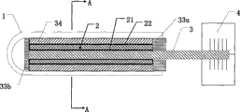
图1是本发明的太阳能热管温差发电装置剖面结构示意图。Fig. 1 is a schematic cross-sectional structure diagram of a solar heat pipe thermoelectric power generation device of the present invention.
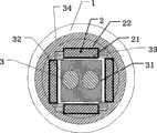
图2是图1中A-A剖视图。Fig. 2 is a sectional view of A-A in Fig. 1 .
图3是本发明太阳能热管温差发电装置另一种实施方式的示意图。Fig. 3 is a schematic diagram of another embodiment of the solar heat pipe thermoelectric power generation device of the present invention.
图4是本发明太阳能热管温差发电装置第三种实施方式的示意图。Fig. 4 is a schematic diagram of a third embodiment of the solar heat pipe thermoelectric power generation device of the present invention.
具体实施方式Detailed ways
参见图1、2,本发明的太阳能温差发电装置,包括内置有温差电池2的筒状的太阳能集热器1,太阳能集热器1内设有冷却管路3,外部设有与冷却管路3相连的散热系统4,散热系统4与冷却管路3的内部相通。Referring to Figures 1 and 2, the solar thermoelectric power generation device of the present invention includes a cylindrical
太阳能集热器1是太阳能真空集热管。The
温差电池2共有四块分布于冷却管路3四周,每个温差电池2的冷端21与冷却管路3的外表面接触换热,温差电池2的热端22与太阳能集热器1的内表面接触换热。There are four
冷却管路3外套有套管31,套管31外表面与温差电池2的冷端21形状相应,套管31内表面与冷却管路3形状相应。温差电池2的冷端21和冷却管路3的外表面之间涂有一层导热物质32。The
相邻近的两块温差电池2之间填充有隔热材料33,太阳能集热器1的两端分布填充有隔热材料33a和隔热材料33b。
温差电池2的热端22和太阳能集热器1内表面之间填充有导热体34。A
图3给出了本发明的另一个实施方式的示意图,它包括太阳能集热器1、温差电池2、冷却管路3、散热系统4、套管31、隔热材料33a、隔热材料33b和导热体34。Fig. 3 has provided the schematic diagram of another embodiment of the present invention, and it comprises
太阳能集热器1采用太阳能热水器中常用的U型太阳能真空集热管,冷却管路3使用超导热管,散热系统4为一水箱。超导热管放入套管31内,温差电池2的冷端21紧贴于套管31的周围。The
超导热管、套管31以及温差电池2一起放置于U型太阳能真空集热管中。温差电池2的热端22紧贴于导热体34的一面,导热体34的另一面紧贴于U型太阳能真空集热管的内侧面,导热体34使用金属铜片折叠而成。The superconducting heat pipe, the
超导热管的冷凝端42放置于散热系统4即水箱中。The condensing
整个装置和水平面成一定角度放置,放置角度满足超导热管工作时的要求即可。The whole device is placed at a certain angle with the horizontal plane, and the placement angle only needs to meet the working requirements of the superconducting heat pipe.
装置工作时,真空集热管把直射、散射以及其它反射面反射的太阳光转化为热量,并且通过导热体34把热量传递到温差电池2的热端22。从而使温差电池2开始工作产生电能。为了使温差电池2能够正常工作,应该保持温差电池2的热端和冷端有足够的温差。由于温差电池2本身具有传热特性,随着温差电池2的热端22的温度升高,温差电池2的冷端21的温度也会升高,当温差电池2的冷端21的热量会通过套管31传递到超导热管的蒸发端41,此时超导热管内的工质将会受热蒸发变为气态,气态的工质会跑到超导热管的上端即冷凝端42,冷凝端42被散热系统4冷却,这样超导热管中气态的工质又会变为液态。受到重力的作用,液态工质又会流会到超导热管的蒸发端41并重新被加热蒸发和冷凝,如此不断循环,不断带走温差电池冷端21的热量,从而保证了持温差电池热端22和冷端21的温差,使其正常发电。When the device is working, the vacuum heat collecting tube converts direct sunlight, scattering sunlight and sunlight reflected by other reflective surfaces into heat, and transfers the heat to the
图4给出了本发明的另一个实施实例的示意图,它包括太阳能集热器1、温差电池2、冷却管路3、散热系统4、套管31、隔热材料33a、导热体34。FIG. 4 shows a schematic diagram of another embodiment of the present invention, which includes a
太阳能集热器1采用直通型太阳能真空集热管,冷却管路3使用环路的结构,散热系统4为一水箱,它和冷却管路3连接在一起。The
冷却管路3放入套管31内,温差电池2的冷端21紧贴于套管31的周围。The
冷却管路3、套管31以及温差电池2一起放置于直通型太阳能真空集热管中。温差电池2的热端22紧贴于导热体34的一面,导热体34的另一面紧贴于直通型太阳能真空集热管的内侧面,导热体34使用金属铜片折叠而成。The
装置工作时,真空集热管把直射、散射以及其它反射面反射的太阳光转化为热量,并且通过导热体34把热量传递到温差电池2的热端22。从而使温差电池2开始工作产生电能。为了使温差电池2能够正常工作,应该保持温差电池2的热端22和冷端21有足够的温差。由于温差电池2本身具有传热特性,随着温差电池2的热端22的温度升高,温差电池2的冷端21的温度也会升高,当温差电池2的冷端21的热量会通过套管31传递到冷却管路3上,此时冷却管路内的工质受热后将膨胀上升,进入冷却水箱并被冷却,冷却后的工质将流回冷却管路中。为了提高工质的流速,可以使整个装置和水平面成一定角度放置,利用重力使工质流动,也可以在冷却管路的内部安装一个小水泵,帮助工质的流动。When the device is working, the vacuum heat collecting tube converts direct sunlight, scattering sunlight and sunlight reflected by other reflective surfaces into heat, and transfers the heat to the
工质的流动不断带走温差电池冷端21的热量,从而保证了持温差电池热端22和冷端21的温差,使其正常发电。为了提高散热效率,冷却管路还可以采用蛇形多弯结构。The flow of the working medium continuously takes away the heat from the
以上列举的仅是本发明的若干个具体实施例,本发明不限于以上实施例,还可以有许多变形,本领域的普通技术人员能从本发明公开的内容直接导出或联想到的所有变形,均应认为是本发明的保护范围。What enumerated above is only several specific embodiments of the present invention, and the present invention is not limited to above embodiment, also can have many deformations, all deformations that those of ordinary skill in the art can directly derive or associate from the content disclosed in the present invention, All should be considered as protection scope of the present invention.
Claims (8)
Translated fromChinesePriority Applications (1)
| Application Number | Priority Date | Filing Date | Title |
|---|---|---|---|
| CN 200910097076CN101534077A (en) | 2009-03-31 | 2009-03-31 | Solar energy thermo-electric generation device |
Applications Claiming Priority (1)
| Application Number | Priority Date | Filing Date | Title |
|---|---|---|---|
| CN 200910097076CN101534077A (en) | 2009-03-31 | 2009-03-31 | Solar energy thermo-electric generation device |
Publications (1)
| Publication Number | Publication Date |
|---|---|
| CN101534077Atrue CN101534077A (en) | 2009-09-16 |
Family
ID=41104511
Family Applications (1)
| Application Number | Title | Priority Date | Filing Date |
|---|---|---|---|
| CN 200910097076PendingCN101534077A (en) | 2009-03-31 | 2009-03-31 | Solar energy thermo-electric generation device |
Country Status (1)
| Country | Link |
|---|---|
| CN (1) | CN101534077A (en) |
Cited By (16)
| Publication number | Priority date | Publication date | Assignee | Title |
|---|---|---|---|---|
| WO2011091620A1 (en)* | 2010-01-29 | 2011-08-04 | 中国科学院广州能源研究所 | System for thermoelectric converting type solar thermal power generation |
| WO2011160293A1 (en)* | 2010-06-23 | 2011-12-29 | 常州天合光能有限公司 | Efficient heat shield for silicon single crystal furnace |
| CN102355168A (en)* | 2011-09-30 | 2012-02-15 | 广东工业大学 | Solar energy temperature difference generation device |
| CN102487259A (en)* | 2009-10-15 | 2012-06-06 | 何仁城 | Method and device for generating power by using temperature difference |
| CN102721202A (en)* | 2012-06-08 | 2012-10-10 | 无锡旭能光热电能源有限公司 | Bi-pass thermovoltaic vacuum tube |
| CN102748881A (en)* | 2012-05-28 | 2012-10-24 | 无锡旭能光热电能源有限公司 | Inner condensation thermovoltaic vacuum tube |
| CN102889696A (en)* | 2012-10-26 | 2013-01-23 | 华北电力大学 | Pyroelectric co-production device of solar water heater |
| CN104025327A (en)* | 2011-12-26 | 2014-09-03 | 中沼忠司 | Thermoelectric power generation device |
| CN104390502A (en)* | 2014-11-06 | 2015-03-04 | 吴速 | Composite heat pipe |
| CN106160579A (en)* | 2014-09-01 | 2016-11-23 | 现代自动车株式会社 | Vehicle thermoelectric generating device |
| CN106412017A (en)* | 2016-08-31 | 2017-02-15 | 重庆伟睿科技有限公司 | Adjacent pushing system |
| CN107733286A (en)* | 2017-11-15 | 2018-02-23 | 肇庆市高新区晓靖科技有限公司 | A kind of temperature difference electricity generation device using solar energy |
| CN107947638A (en)* | 2017-11-28 | 2018-04-20 | 中国矿业大学 | A kind of solar energy temperature difference generating set based on double pulsating heat pipes |
| CN108258938A (en)* | 2018-03-21 | 2018-07-06 | 广东美的厨房电器制造有限公司 | Gas-cooker thermo-electric generation structure |
| CN108494363A (en)* | 2018-04-13 | 2018-09-04 | 杨迪生 | A kind of energy storage device that solar energy wind is photothermal integrated and its energy storage method |
| CN109883063A (en)* | 2019-04-16 | 2019-06-14 | 吉林大学 | A hair-type solar collector and its power generation control method |
- 2009
- 2009-03-31CNCN 200910097076patent/CN101534077A/enactivePending
Cited By (22)
| Publication number | Priority date | Publication date | Assignee | Title |
|---|---|---|---|---|
| CN102487259A (en)* | 2009-10-15 | 2012-06-06 | 何仁城 | Method and device for generating power by using temperature difference |
| WO2011091620A1 (en)* | 2010-01-29 | 2011-08-04 | 中国科学院广州能源研究所 | System for thermoelectric converting type solar thermal power generation |
| WO2011160293A1 (en)* | 2010-06-23 | 2011-12-29 | 常州天合光能有限公司 | Efficient heat shield for silicon single crystal furnace |
| CN102355168A (en)* | 2011-09-30 | 2012-02-15 | 广东工业大学 | Solar energy temperature difference generation device |
| CN102355168B (en)* | 2011-09-30 | 2014-04-02 | 广东工业大学 | Solar energy temperature difference generation device |
| CN104025327B (en)* | 2011-12-26 | 2017-02-22 | 中沼忠司 | Thermoelectric power generation device |
| CN104025327A (en)* | 2011-12-26 | 2014-09-03 | 中沼忠司 | Thermoelectric power generation device |
| CN106340583B (en)* | 2011-12-26 | 2018-10-30 | 中沼忠司 | Thermoelectric generating device |
| CN106340583A (en)* | 2011-12-26 | 2017-01-18 | 中沼忠司 | Thermoelectric generator |
| CN102748881A (en)* | 2012-05-28 | 2012-10-24 | 无锡旭能光热电能源有限公司 | Inner condensation thermovoltaic vacuum tube |
| CN102721202A (en)* | 2012-06-08 | 2012-10-10 | 无锡旭能光热电能源有限公司 | Bi-pass thermovoltaic vacuum tube |
| CN102889696A (en)* | 2012-10-26 | 2013-01-23 | 华北电力大学 | Pyroelectric co-production device of solar water heater |
| CN106160579A (en)* | 2014-09-01 | 2016-11-23 | 现代自动车株式会社 | Vehicle thermoelectric generating device |
| CN104390502A (en)* | 2014-11-06 | 2015-03-04 | 吴速 | Composite heat pipe |
| CN106412017A (en)* | 2016-08-31 | 2017-02-15 | 重庆伟睿科技有限公司 | Adjacent pushing system |
| CN107733286A (en)* | 2017-11-15 | 2018-02-23 | 肇庆市高新区晓靖科技有限公司 | A kind of temperature difference electricity generation device using solar energy |
| CN107947638A (en)* | 2017-11-28 | 2018-04-20 | 中国矿业大学 | A kind of solar energy temperature difference generating set based on double pulsating heat pipes |
| CN108258938A (en)* | 2018-03-21 | 2018-07-06 | 广东美的厨房电器制造有限公司 | Gas-cooker thermo-electric generation structure |
| CN108494363A (en)* | 2018-04-13 | 2018-09-04 | 杨迪生 | A kind of energy storage device that solar energy wind is photothermal integrated and its energy storage method |
| CN108494363B (en)* | 2018-04-13 | 2024-05-14 | 杨迪生 | Solar wind-solar-heat integrated energy storage device and energy storage method thereof |
| CN109883063A (en)* | 2019-04-16 | 2019-06-14 | 吉林大学 | A hair-type solar collector and its power generation control method |
| CN109883063B (en)* | 2019-04-16 | 2023-08-22 | 吉林大学 | Hair-type solar collector and method for controlling power generation thereof |
Similar Documents
| Publication | Publication Date | Title |
|---|---|---|
| CN101534077A (en) | Solar energy thermo-electric generation device | |
| CN102487255B (en) | Solar energy composite utilizes device | |
| CN103398474B (en) | Solar photovoltaic-photothermal-thermoelectric comprehensive utilization system | |
| CN106839463A (en) | Flat-plate type micro heat pipe array type solar air heat-collecting, accumulation of heat integrated apparatus | |
| CN201363922Y (en) | Heat tube tank type solar collector | |
| CN102881758B (en) | A kind of cogeneration system | |
| CN100555676C (en) | Closed-loop capillary solar photovoltaic thermoelectric plate | |
| CN105387634A (en) | Jet type efficient heat exchange solar heat absorption device | |
| CN101387451B (en) | Closed-loop capillary pipe plate type solar heat collector | |
| CN106568118A (en) | Condensation solar energy heat pump heating power generation system | |
| CN211625735U (en) | Flat-plate solar water heating system | |
| CN202119308U (en) | Radiation type flat hot tube radiator | |
| CN205373077U (en) | High -efficient heat transfer solar energy heat sink of efflux | |
| CN205249143U (en) | Heat pipe formula spotlight photovoltaic cooling heating device | |
| CN103095184B (en) | Waste heat utilization thermoelectric power generation pipeline device | |
| CN206890915U (en) | A kind of phase-transition heat-storage solar air source double heat source heat pump hot water electric generating apparatus | |
| CN116734494A (en) | Flat plate heat pipe-phase change material coupled photovoltaic photothermal composite collector | |
| CN112594969B (en) | Nano-fluid micro-channel photovoltaic-solar heat pump system | |
| CN202869023U (en) | Parallel connection cavity type solar thermal collector | |
| CN202119131U (en) | Antifreezing water pipe matched with solar equipment | |
| CN103138649A (en) | Power generation device with complementation of solar energy and biomass energy achievable | |
| CN209181296U (en) | Balcony wall-mounted solar water heating device | |
| CN108809253B (en) | A high-power concentrating photovoltaic thermal control device | |
| CN101737966A (en) | Vacuum-tube heat-pipe combined high-temperature high-pressure steam solar heater | |
| CN202013029U (en) | Heat transfer device for heat pipe type solar heat collector |
Legal Events
| Date | Code | Title | Description |
|---|---|---|---|
| C06 | Publication | ||
| PB01 | Publication | ||
| C10 | Entry into substantive examination | ||
| SE01 | Entry into force of request for substantive examination | ||
| C12 | Rejection of a patent application after its publication | ||
| RJ01 | Rejection of invention patent application after publication | Open date:20090916 |